EP4214397B1 - Rohrkomponente mit einer umhüllung einer kehlnaht und verfahren zur herstellung einer rohrkomponente - Google Patents
Rohrkomponente mit einer umhüllung einer kehlnaht und verfahren zur herstellung einer rohrkomponente Download PDFInfo
- Publication number
- EP4214397B1 EP4214397B1 EP21777856.2A EP21777856A EP4214397B1 EP 4214397 B1 EP4214397 B1 EP 4214397B1 EP 21777856 A EP21777856 A EP 21777856A EP 4214397 B1 EP4214397 B1 EP 4214397B1
- Authority
- EP
- European Patent Office
- Prior art keywords
- tubing component
- metallic layer
- inner tube
- protective metallic
- outer tube
- Prior art date
- Legal status (The legal status is an assumption and is not a legal conclusion. Google has not performed a legal analysis and makes no representation as to the accuracy of the status listed.)
- Active
Links
Images

Classifications
-
- E—FIXED CONSTRUCTIONS
- E21—EARTH OR ROCK DRILLING; MINING
- E21B—EARTH OR ROCK DRILLING; OBTAINING OIL, GAS, WATER, SOLUBLE OR MELTABLE MATERIALS OR A SLURRY OF MINERALS FROM WELLS
- E21B36/00—Heating, cooling or insulating arrangements for boreholes or wells, e.g. for use in permafrost zones
- E21B36/003—Insulating arrangements
-
- B—PERFORMING OPERATIONS; TRANSPORTING
- B23—MACHINE TOOLS; METAL-WORKING NOT OTHERWISE PROVIDED FOR
- B23K—SOLDERING OR UNSOLDERING; WELDING; CLADDING OR PLATING BY SOLDERING OR WELDING; CUTTING BY APPLYING HEAT LOCALLY, e.g. FLAME CUTTING; WORKING BY LASER BEAM
- B23K31/00—Processes relevant to this subclass, specially adapted for particular articles or purposes, but not covered by only one of the preceding main groups
- B23K31/02—Processes relevant to this subclass, specially adapted for particular articles or purposes, but not covered by only one of the preceding main groups relating to soldering or welding
-
- F—MECHANICAL ENGINEERING; LIGHTING; HEATING; WEAPONS; BLASTING
- F16—ENGINEERING ELEMENTS AND UNITS; GENERAL MEASURES FOR PRODUCING AND MAINTAINING EFFECTIVE FUNCTIONING OF MACHINES OR INSTALLATIONS; THERMAL INSULATION IN GENERAL
- F16L—PIPES; JOINTS OR FITTINGS FOR PIPES; SUPPORTS FOR PIPES, CABLES OR PROTECTIVE TUBING; MEANS FOR THERMAL INSULATION IN GENERAL
- F16L58/00—Protection of pipes or pipe fittings against corrosion or incrustation
- F16L58/18—Protection of pipes or pipe fittings against corrosion or incrustation specially adapted for pipe fittings
- F16L58/182—Protection of pipes or pipe fittings against corrosion or incrustation specially adapted for pipe fittings for screw-threaded joints
-
- F—MECHANICAL ENGINEERING; LIGHTING; HEATING; WEAPONS; BLASTING
- F16—ENGINEERING ELEMENTS AND UNITS; GENERAL MEASURES FOR PRODUCING AND MAINTAINING EFFECTIVE FUNCTIONING OF MACHINES OR INSTALLATIONS; THERMAL INSULATION IN GENERAL
- F16L—PIPES; JOINTS OR FITTINGS FOR PIPES; SUPPORTS FOR PIPES, CABLES OR PROTECTIVE TUBING; MEANS FOR THERMAL INSULATION IN GENERAL
- F16L59/00—Thermal insulation in general
- F16L59/06—Arrangements using an air layer or vacuum
- F16L59/065—Arrangements using an air layer or vacuum using vacuum
-
- F—MECHANICAL ENGINEERING; LIGHTING; HEATING; WEAPONS; BLASTING
- F16—ENGINEERING ELEMENTS AND UNITS; GENERAL MEASURES FOR PRODUCING AND MAINTAINING EFFECTIVE FUNCTIONING OF MACHINES OR INSTALLATIONS; THERMAL INSULATION IN GENERAL
- F16L—PIPES; JOINTS OR FITTINGS FOR PIPES; SUPPORTS FOR PIPES, CABLES OR PROTECTIVE TUBING; MEANS FOR THERMAL INSULATION IN GENERAL
- F16L9/00—Rigid pipes
- F16L9/02—Rigid pipes of metal
-
- F—MECHANICAL ENGINEERING; LIGHTING; HEATING; WEAPONS; BLASTING
- F16—ENGINEERING ELEMENTS AND UNITS; GENERAL MEASURES FOR PRODUCING AND MAINTAINING EFFECTIVE FUNCTIONING OF MACHINES OR INSTALLATIONS; THERMAL INSULATION IN GENERAL
- F16L—PIPES; JOINTS OR FITTINGS FOR PIPES; SUPPORTS FOR PIPES, CABLES OR PROTECTIVE TUBING; MEANS FOR THERMAL INSULATION IN GENERAL
- F16L9/00—Rigid pipes
- F16L9/18—Double-walled pipes; Multi-channel pipes or pipe assemblies
-
- B—PERFORMING OPERATIONS; TRANSPORTING
- B23—MACHINE TOOLS; METAL-WORKING NOT OTHERWISE PROVIDED FOR
- B23K—SOLDERING OR UNSOLDERING; WELDING; CLADDING OR PLATING BY SOLDERING OR WELDING; CUTTING BY APPLYING HEAT LOCALLY, e.g. FLAME CUTTING; WORKING BY LASER BEAM
- B23K2101/00—Articles made by soldering, welding or cutting
- B23K2101/04—Tubular or hollow articles
- B23K2101/06—Tubes
Definitions
- the present disclosure relates to the field of vacuum insulated tubing for use in oil and gas wells.
- the present disclosure further relates to cladding of a fillet welding for vacuum insulated tubing and methods for making this cladding of a fillet welding.
- the present disclosure relates to vacuum insulated tubing for high pressure and high temperature conditions.
- Vacuum insulated tubing is a known device for use in such wells to mitigate the annular pressure buildup.
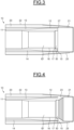
- FIG 1 shown is a prior art vacuum insulated tubing 1.
- a vacuum insulated tubing for mitigating annular pressure buildup in a wellbore casing annulus of an oil or gas well having an ability to withstand high pressure and high temperature conditions and to resist to oil and H 2 S corrosion.
- the vacuum insulated tubing 10 also referred to as the tubing component 10 has an inner tube 11, having a maximum outer diameter 12, a minimum outer diameter 13 defining a vacuum space 14.
- the inner tube 11 has a first internal diameter ID along a first length 15 starting from each of the very end of said tube.
- the inner tube 11 has also a second, smaller internal diameter ID' along a second length 16 beyond the first length 15.
- the first length 15 has a length of 12.7 mm
- the first internal diameter ID has a diameter of 96.5 mm
- the second internal diameter ID' has a diameter of 91 mm.
- the inner tube 11 comprises a bevel 17 between said first and second length 15 and 16. This bevel 17 makes for example an angle of 60° with a transversal plane.
- the difference ID-ID' is larger than 5 mm.
- the bevel 17 is created during manufacturing of the inner tube 11.
- the tubing component 10 also has an outer tube 20, having a constant inner diameter for its internal surface 21 and an outer diameter 22.
- the outer tube 20 fits around the inner tube 11 such that the end of the outer tube 20 extends beyond the inner tube 11.
- the outer tube has an outer diameter of 155 mm.
- the inner tube can have a maximum outer diameter of 127 mm.
- the outer tube 20 and the inner tube 11 can be made from a suitable material for providing the required strength.
- the outer tube 20 and the inner tube 11 are made from an alloy having a yield strength of at least 125 ksi.
- the outer tube 20 and the inner tube 11 are made from a weldable chromium steel alloy comprising at least 13% of chromium, also referred to as 13Cr steel.
- the vacuum space 14 is formed between the outer tube 20 and the inner tube 11, having a vacuum in between.
- the vacuum is created using any suitable technology employed in known vacuum insulated tubing manufacturing.
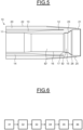
- a protective metallic layer 24 completely covers the surface of the fillet weld 23.
- the protective metallic layer 24 is an overlay weld obtained by Gas Tungsten Arc Welding or Tungsten Inert Gas welding, also referred to as cladding.
- the fillet weld 23 and the protective metallic layer 24 do not extend, i.e., protrude, beyond the first internal diameter ID of the inner tube 11; therefore, the second internal diameter ID' of the tubing component is not impacted by the fillet weld 23 and the protective metallic layer 24.
- the protective metallic layer 24 has a thickness from about 3 mm to about 3.5 mm.
- the thickness can be 3.2 mm.
- the protective metallic layer 24 can be formed by depositing the material in two passes.
- the protective metallic layer 24 material deposited in the two passes can have substantially the same thickness.
- the thickness of each of the two passes can be 1.6 mm.
- the surface of the fillet weld 23 is prepared prior to the deposition of the protective metallic layer 24 by beveling, modifying or polishing the fillet weld 23 to help ensure complete coverage and bonding of the fillet weld 23 by the overlay weld.
- the protective metallic layer 24 can extend beyond the edges of the fillet weld, e.g., 12.7 mm in the axial direction of the tubing component 10, to also cover the adjacent internal surfaces of the inner tube 11 and of the outer tube 20.
- the first length 15 of the internal surface of the inner tube 11 can be overlaps, i.e.
- the cladding of the protective metallic layer 24 is precisely done with respect to the bevel 17.
- a second specified distance SD for example of 12.7 mm can be overlaps on the internal surface 21 of the outer tube 20.
- the thickness of the protective metallic layer 24 is equal or smaller than (ID-ID')/2 over the first length 15, wherein the difference ID - ID' is larger than 4 mm, preferably larger than 5.5 mm.
- the protective metallic layer 24 can be thicker over the internal surface 21 of the outer tube 20.
- the protective metallic layer 24 is made from a suitable overlay weld material for protecting the fillet weld 23 under the conditions the tubing component will experience in the field system.
- the overlay weld material is made of a corrosion resistant nickel-based alloy such as an alloy including Nickel, Chromium and Molybdenum wherein Nickel amounts to more than 50%.
- the protective metallic layer 24 material is Inconel 625, that permits an excellent bonding.
- the dilution iron can be no more than 5% to 10 % for corrosion resistance of the overlay weld. This is achieved by depositing the protective metallic layer 24 material in two passes by making a bottom layer and at least a top layer on top of the bottom layer in order to reduce dilution of iron near the free surface of the layer. The thickness of the protective metallic layer 24 is thus high.
- a first length 15 with a first internal diameter ID and the bevel 17 of the inner tube 11 have been designed, as described above.
- This first internal diameter ID is bigger than the second internal diameter ID' and permits to an existing design of tubing to house the cladding without reducing the drift.
- the first internal diameter ID is also small enough to allow the fillet weld to match with the tubing strength required and to facilitate the welding of the fillet weld 23.
Landscapes
- Engineering & Computer Science (AREA)
- General Engineering & Computer Science (AREA)
- Mechanical Engineering (AREA)
- Mining & Mineral Resources (AREA)
- Geology (AREA)
- Life Sciences & Earth Sciences (AREA)
- Fluid Mechanics (AREA)
- Physics & Mathematics (AREA)
- General Life Sciences & Earth Sciences (AREA)
- Geochemistry & Mineralogy (AREA)
- Environmental & Geological Engineering (AREA)
- Butt Welding And Welding Of Specific Article (AREA)
- Earth Drilling (AREA)
- Rigid Pipes And Flexible Pipes (AREA)
- Arc Welding In General (AREA)
Claims (15)
- Röhrenkomponente (10), geeignet für die Verwendung in Öl- und Gasbohrlöchern, umfassend eine äußere Röhre (20) und eine innere Röhre (11) innerhalb der äußeren Röhre (20), wobei die äußere Röhre (20) und die innere Röhre (11) aus Stahl gefertigt sind, wobei die Röhren (11, 20) dazu ausgelegt sind, einen Raum (14) über eine bestimmte Länge zwischen einander zu erzeugen, wobei die Röhrenkomponente (10) dadurch gekennzeichnet ist, dassa. jedes Ende der inneren Röhre (11) über eine kegelstumpfförmige Kehlschweißnaht (23) an einer Innenoberfläche (21) der äußeren Röhre (20) gesichert ist, sodass der Raum (14) dicht ist,b. die innere Röhre (11) aufweist:i. einen ersten Innendurchmesser (ID) entlang einer ersten Länge (15), von jedem Ende der Röhre aus gemessen,ii. einen zweiten, kleineren Innendurchmesser (ID') entlang einer zweiten Länge (16), über die erste Länge (15) hinaus,c. die Röhrenkomponente (10) ferner eine schützende Metallschicht (24) einschließt, die sich mindestens über die Kehlschweißnaht (23) erstreckt.
- Röhrenkomponente (10) nach Anspruch 1, wobei die schützende Metallschicht (24) eine Auftragschweißnaht ist.
- Röhrenkomponente (10) nach Anspruch 1, wobei die schützende Metallschicht (24) aus einer korrosionsbeständigen Nickellegierung gefertigt ist.
- Röhrenkomponente (10) nach Anspruch 1, wobei die schützende Metallschicht (24) sich ferner über die Kehlschweißnaht (23) hinaus hin zum Inneren der inneren Röhre (11) und hin zum Inneren der äußeren Röhre (20) erstreckt.
- Röhrenkomponente (10) nach Anspruch 1, wobei die schützende Metallschicht (24) die Innenoberfläche der inneren Röhre (11) über einen ersten festgelegten Abstand (FD) überlappt.
- Röhrenkomponente (10) nach Anspruch 1, wobei die schützende Metallschicht (24) die Innenoberfläche der inneren Röhre über die erste Länge (15) überlappt.
- Röhrenkomponente (10) nach Anspruch 1, wobei die schützende Metallschicht (24) die Innenoberfläche (21) der äußeren Röhre (20) über einen zweiten festgelegten Abstand (SD) überlappt.
- Röhrenkomponente (10) nach Anspruch 5, wobei die Dicke der schützenden Metallschicht (24) über den ersten festgelegten Abstand (FD) höchstens (ID - ID') / 2 beträgt.
- Röhrenkomponente (10) nach Anspruch 1, wobei die innere Röhre (11) eine Abschrägung (17) zwischen der ersten (FD) und der zweiten (SD) Länge aufweist.
- Röhrenkomponente (10) nach Anspruch 1, wobei die äußere Röhre (20) ein Außengewinde (25) an mindestens einem Ende aufweist, um eine Verbindung zu einem röhrenförmigen Element zu ermöglichen.
- Verfahren zum Erzeugen einer Röhrenkomponente (10) nach einem der Ansprüche 1 bis 10, das Verfahren umfassend:a. Bereitstellen (31), vor dem Zusammenbauen, einer inneren Röhre (11) mit:i. einem ersten Innendurchmesser ID entlang einer ersten Länge (15), von jedem Ende der Röhre (11) aus gemessen,ii. einem zweiten, kleineren Innendurchmesser ID' entlang einer zweiten Länge (16), über die erste Länge (15) hinaus,b. Positionieren (32) der inneren Röhre (11) innerhalb der äußeren Röhre (20),c. Verschweißen (33) eines jeden Endes der inneren Röhre (11) an die Innenoberfläche (21) der äußeren Röhre (20), um eine kegelstumpfförmige Kehlschweißnaht (23) zu erzeugen, die die Röhren (11, 20) aneinander sichert, sodass der Raum (14) dicht ist,d. Ausbilden (35) einer schützenden Metallschicht (24), die sich mindestens über die Schweißnaht (23) erstreckt.
- Verfahren nach Anspruch 11, wobei die schützende Metallschicht (24) eine Auftragschweißnaht ist.
- Verfahren nach Anspruch 11, wobei die schützende Metallschicht (24) in zwei Durchläufen ausgebildet wird, indem eine untere Schicht und mindestens eine auf der unteren Schicht angeordnete obere Schicht erzeugt wird, um eine Verdünnung des Eisens nahe der freien Oberfläche der Schicht zu verringern.
- Verfahren nach Anspruch 11, ferner mit einem Abschrägungsvorgang (34) an der Kehlschweißnaht (23), um Oberflächenoxide zu entfernen, wobei der Abschrägungsvorgang vorzugsweise nach dem Schweißen und vor dem Ausbilden der schützenden Metallschicht (24) durchgeführt wird.
- Verfahren nach Anspruch 11, ferner mit einem Spannungsabbauvorgang (36) durch eine Wärmebehandlung nach dem Schweißen.
Applications Claiming Priority (2)
| Application Number | Priority Date | Filing Date | Title |
|---|---|---|---|
| US17/025,785 US11739862B2 (en) | 2020-09-18 | 2020-09-18 | Tubing component having a cladding of fillet weld, and method for producing a tubing component |
| PCT/IB2021/058439 WO2022058917A1 (en) | 2020-09-18 | 2021-09-16 | Tubing component having a cladding of fillet weld, and method for producing a tubing component |
Publications (3)
| Publication Number | Publication Date |
|---|---|
| EP4214397A1 EP4214397A1 (de) | 2023-07-26 |
| EP4214397B1 true EP4214397B1 (de) | 2025-07-09 |
| EP4214397C0 EP4214397C0 (de) | 2025-07-09 |
Family
ID=77914415
Family Applications (1)
| Application Number | Title | Priority Date | Filing Date |
|---|---|---|---|
| EP21777856.2A Active EP4214397B1 (de) | 2020-09-18 | 2021-09-16 | Rohrkomponente mit einer umhüllung einer kehlnaht und verfahren zur herstellung einer rohrkomponente |
Country Status (6)
| Country | Link |
|---|---|
| US (1) | US11739862B2 (de) |
| EP (1) | EP4214397B1 (de) |
| JP (1) | JP7697003B2 (de) |
| CN (1) | CN116547438A (de) |
| MX (1) | MX2023003243A (de) |
| WO (1) | WO2022058917A1 (de) |
Families Citing this family (1)
| Publication number | Priority date | Publication date | Assignee | Title |
|---|---|---|---|---|
| ES2988741T3 (es) * | 2021-12-14 | 2024-11-21 | Vallourec Tube Alloy Llc | Tubo aislado de alta resistencia |
Family Cites Families (20)
| Publication number | Priority date | Publication date | Assignee | Title |
|---|---|---|---|---|
| CA926377A (en) * | 1970-08-25 | 1973-05-15 | Can-Tex Drilling And Exploration Ltd. | Dual concentric drillpipe |
| DE2626813C3 (de) * | 1976-06-15 | 1980-10-30 | Bayer Ag, 5090 Leverkusen | Verfahren zur Herstellung lösbarer Verbindungen bei einem mantelbeheizten Rohrleitungssystem |
| US4415184A (en) * | 1981-04-27 | 1983-11-15 | General Electric Company | High temperature insulated casing |
| JPS5934086A (ja) * | 1982-08-16 | 1984-02-24 | 川崎重工業株式会社 | 耐蝕二重管構造 |
| US4673652A (en) * | 1982-10-12 | 1987-06-16 | Baker Oil Tools, Inc. | Method of testing and reconditioning insulating tubular conduits |
| US4635967A (en) * | 1985-03-29 | 1987-01-13 | Kawasaki Thermal Systems, Inc. | Internal seal for insulated steam injection casing assembly |
| JPS63101599A (ja) * | 1986-10-16 | 1988-05-06 | 住友金属工業株式会社 | 油井管用断熱二重管 |
| JPS631886A (ja) * | 1987-03-03 | 1988-01-06 | 川崎重工業株式会社 | 端部前処理溶接ユニツト二重管構造 |
| US7207603B2 (en) | 2003-03-11 | 2007-04-24 | Grant Prideco, L.P. | Insulated tubular assembly |
| CN101270445B (zh) * | 2007-03-23 | 2010-10-06 | 宝山钢铁股份有限公司 | 一种耐高温隔热油管的制造方法 |
| CN102071879B (zh) | 2011-01-07 | 2013-07-10 | 中国石油集团渤海石油装备制造有限公司 | 一种预应力隔热油管 |
| RU2487228C1 (ru) * | 2011-12-20 | 2013-07-10 | Общество С Ограниченной Ответственностью "Тмк-Премиум Сервис" | Секция теплоизолированной колонны |
| US9032774B1 (en) * | 2013-12-13 | 2015-05-19 | The Boeing Company | Laminated forming dies |
| JP6199725B2 (ja) | 2013-12-16 | 2017-09-20 | 三菱重工業株式会社 | 配管接続方法及び配管接続構造 |
| DE102016210415A1 (de) * | 2016-06-13 | 2018-01-11 | MTU Aero Engines AG | Rohranordnung mit Stützabschnitten am Außenrohr |
| US11072036B2 (en) | 2016-12-29 | 2021-07-27 | Spinduction Weld, Inc. | Concentric welded pipes with condition monitoring capability and method of manufacture |
| JP7087756B2 (ja) | 2018-07-18 | 2022-06-21 | 日本製鉄株式会社 | 高炉用羽口およびその製造方法 |
| JP7215010B2 (ja) | 2018-08-03 | 2023-01-31 | 日本製鉄株式会社 | 高炉用羽口およびその製造方法 |
| CN109578752B (zh) | 2019-01-29 | 2024-02-23 | 信达科创(唐山)石油设备有限公司 | 一种超长保温钢套钢管道及其加工工艺 |
| US11118426B2 (en) | 2019-06-17 | 2021-09-14 | Chevron U.S.A. Inc. | Vacuum insulated tubing for high pressure, high temperature wells, and systems and methods for use thereof, and methods for making |
-
2020
- 2020-09-18 US US17/025,785 patent/US11739862B2/en active Active
-
2021
- 2021-09-16 JP JP2023517845A patent/JP7697003B2/ja active Active
- 2021-09-16 WO PCT/IB2021/058439 patent/WO2022058917A1/en not_active Ceased
- 2021-09-16 CN CN202180063409.6A patent/CN116547438A/zh active Pending
- 2021-09-16 EP EP21777856.2A patent/EP4214397B1/de active Active
- 2021-09-16 MX MX2023003243A patent/MX2023003243A/es unknown
Also Published As
| Publication number | Publication date |
|---|---|
| US11739862B2 (en) | 2023-08-29 |
| MX2023003243A (es) | 2023-04-14 |
| WO2022058917A1 (en) | 2022-03-24 |
| CN116547438A (zh) | 2023-08-04 |
| JP7697003B2 (ja) | 2025-06-23 |
| EP4214397C0 (de) | 2025-07-09 |
| US20220090708A1 (en) | 2022-03-24 |
| JP2023541481A (ja) | 2023-10-02 |
| BR112023002972A2 (pt) | 2023-04-04 |
| EP4214397A1 (de) | 2023-07-26 |
Similar Documents
| Publication | Publication Date | Title |
|---|---|---|
| US11072036B2 (en) | Concentric welded pipes with condition monitoring capability and method of manufacture | |
| US6860420B2 (en) | Method of joining metal oilfield tubulars and well provided therewith | |
| US11174685B2 (en) | Enhanced welded pipe, threaded connections, and methods for achieving the same | |
| EP0171416A1 (de) | Isolierte kupplung für bohrkragen und deren herstellung. | |
| EP4214397B1 (de) | Rohrkomponente mit einer umhüllung einer kehlnaht und verfahren zur herstellung einer rohrkomponente | |
| EP3224519B1 (de) | Fluidleitungselement und verfahren zur herstellung des fluidleitungselements | |
| GB2438631A (en) | A bimetal bore seal for connecting and sealing oil and gas tubular members | |
| US20220243845A1 (en) | Threaded joint with shoulder produced by additive manufacturing | |
| EP3389919B1 (de) | Verbindungsverfahren und rohrverbindungsanordnung mit verbesserter ermüdungsfestigkeit von metallischen steigrohren | |
| US9677179B2 (en) | Pipe connector and method | |
| WO2003050380A1 (en) | Multiple seal design for composite risers and tubing for offshore applications | |
| US11118426B2 (en) | Vacuum insulated tubing for high pressure, high temperature wells, and systems and methods for use thereof, and methods for making | |
| EP4127383B1 (de) | Anordnung mit eng kontrolliertem axialspalt für eine schraubverbinderisolierung an vakuumisolierten rohren | |
| US8672621B2 (en) | Welded structural flats on cases to eliminate nozzles | |
| BR112023002972B1 (pt) | Componente tubular possuindo um revestimento de solda de filete, e método de produção de um componente tubular | |
| US12460751B2 (en) | Composite pipe end-fitting | |
| JPS6335333B2 (de) | ||
| EP4198363B1 (de) | Hochfestes isoliertes rohr | |
| CN107191686B (zh) | 可端部螺纹连接的高强度不锈钢复合钢管及其制造方法 | |
| RU2245983C2 (ru) | Лифтовая теплоизолированная труба | |
| US20180066789A1 (en) | High Thermal Efficiency Tube for Conveying Fluids |
Legal Events
| Date | Code | Title | Description |
|---|---|---|---|
| STAA | Information on the status of an ep patent application or granted ep patent |
Free format text: STATUS: UNKNOWN |
|
| STAA | Information on the status of an ep patent application or granted ep patent |
Free format text: STATUS: THE INTERNATIONAL PUBLICATION HAS BEEN MADE |
|
| PUAI | Public reference made under article 153(3) epc to a published international application that has entered the european phase |
Free format text: ORIGINAL CODE: 0009012 |
|
| STAA | Information on the status of an ep patent application or granted ep patent |
Free format text: STATUS: REQUEST FOR EXAMINATION WAS MADE |
|
| 17P | Request for examination filed |
Effective date: 20230327 |
|
| AK | Designated contracting states |
Kind code of ref document: A1 Designated state(s): AL AT BE BG CH CY CZ DE DK EE ES FI FR GB GR HR HU IE IS IT LI LT LU LV MC MK MT NL NO PL PT RO RS SE SI SK SM TR |
|
| DAV | Request for validation of the european patent (deleted) | ||
| DAX | Request for extension of the european patent (deleted) | ||
| GRAP | Despatch of communication of intention to grant a patent |
Free format text: ORIGINAL CODE: EPIDOSNIGR1 |
|
| STAA | Information on the status of an ep patent application or granted ep patent |
Free format text: STATUS: GRANT OF PATENT IS INTENDED |
|
| RIC1 | Information provided on ipc code assigned before grant |
Ipc: F16L 58/18 20060101ALI20250217BHEP Ipc: F16L 59/065 20060101ALI20250217BHEP Ipc: F16L 9/18 20060101ALI20250217BHEP Ipc: E21B 36/00 20060101AFI20250217BHEP |
|
| INTG | Intention to grant announced |
Effective date: 20250228 |
|
| GRAS | Grant fee paid |
Free format text: ORIGINAL CODE: EPIDOSNIGR3 |
|
| GRAA | (expected) grant |
Free format text: ORIGINAL CODE: 0009210 |
|
| STAA | Information on the status of an ep patent application or granted ep patent |
Free format text: STATUS: THE PATENT HAS BEEN GRANTED |
|
| AK | Designated contracting states |
Kind code of ref document: B1 Designated state(s): AL AT BE BG CH CY CZ DE DK EE ES FI FR GB GR HR HU IE IS IT LI LT LU LV MC MK MT NL NO PL PT RO RS SE SI SK SM TR |
|
| REG | Reference to a national code |
Ref country code: GB Ref legal event code: FG4D |
|
| REG | Reference to a national code |
Ref country code: CH Ref legal event code: EP |
|
| REG | Reference to a national code |
Ref country code: IE Ref legal event code: FG4D |
|
| REG | Reference to a national code |
Ref country code: DE Ref legal event code: R096 Ref document number: 602021033859 Country of ref document: DE |
|
| U01 | Request for unitary effect filed |
Effective date: 20250723 |
|
| U07 | Unitary effect registered |
Designated state(s): AT BE BG DE DK EE FI FR IT LT LU LV MT NL PT RO SE SI Effective date: 20250730 |
|
| PGFP | Annual fee paid to national office [announced via postgrant information from national office to epo] |
Ref country code: NO Payment date: 20250825 Year of fee payment: 5 |
|
| PGFP | Annual fee paid to national office [announced via postgrant information from national office to epo] |
Ref country code: GB Payment date: 20250820 Year of fee payment: 5 |
|
| U20 | Renewal fee for the european patent with unitary effect paid |
Year of fee payment: 5 Effective date: 20250912 |