EP4212399A1 - Druckluftbremsanlage für ein fahrzeug und verfahren zum betreiben der druckluftbremsanlage - Google Patents
Druckluftbremsanlage für ein fahrzeug und verfahren zum betreiben der druckluftbremsanlage Download PDFInfo
- Publication number
- EP4212399A1 EP4212399A1 EP23150298.0A EP23150298A EP4212399A1 EP 4212399 A1 EP4212399 A1 EP 4212399A1 EP 23150298 A EP23150298 A EP 23150298A EP 4212399 A1 EP4212399 A1 EP 4212399A1
- Authority
- EP
- European Patent Office
- Prior art keywords
- valve
- valve device
- compressed air
- brake system
- pilot
- Prior art date
- Legal status (The legal status is an assumption and is not a legal conclusion. Google has not performed a legal analysis and makes no representation as to the accuracy of the status listed.)
- Granted
Links
Images

Classifications
-
- B—PERFORMING OPERATIONS; TRANSPORTING
- B60—VEHICLES IN GENERAL
- B60T—VEHICLE BRAKE CONTROL SYSTEMS OR PARTS THEREOF; BRAKE CONTROL SYSTEMS OR PARTS THEREOF, IN GENERAL; ARRANGEMENT OF BRAKING ELEMENTS ON VEHICLES IN GENERAL; PORTABLE DEVICES FOR PREVENTING UNWANTED MOVEMENT OF VEHICLES; VEHICLE MODIFICATIONS TO FACILITATE COOLING OF BRAKES
- B60T15/00—Construction arrangement, or operation of valves incorporated in power brake systems and not covered by groups B60T11/00 or B60T13/00
- B60T15/02—Application and release valves
-
- B—PERFORMING OPERATIONS; TRANSPORTING
- B60—VEHICLES IN GENERAL
- B60T—VEHICLE BRAKE CONTROL SYSTEMS OR PARTS THEREOF; BRAKE CONTROL SYSTEMS OR PARTS THEREOF, IN GENERAL; ARRANGEMENT OF BRAKING ELEMENTS ON VEHICLES IN GENERAL; PORTABLE DEVICES FOR PREVENTING UNWANTED MOVEMENT OF VEHICLES; VEHICLE MODIFICATIONS TO FACILITATE COOLING OF BRAKES
- B60T13/00—Transmitting braking action from initiating means to ultimate brake actuator with power assistance or drive; Brake systems incorporating such transmitting means, e.g. air-pressure brake systems
- B60T13/10—Transmitting braking action from initiating means to ultimate brake actuator with power assistance or drive; Brake systems incorporating such transmitting means, e.g. air-pressure brake systems with fluid assistance, drive, or release
-
- B—PERFORMING OPERATIONS; TRANSPORTING
- B60—VEHICLES IN GENERAL
- B60T—VEHICLE BRAKE CONTROL SYSTEMS OR PARTS THEREOF; BRAKE CONTROL SYSTEMS OR PARTS THEREOF, IN GENERAL; ARRANGEMENT OF BRAKING ELEMENTS ON VEHICLES IN GENERAL; PORTABLE DEVICES FOR PREVENTING UNWANTED MOVEMENT OF VEHICLES; VEHICLE MODIFICATIONS TO FACILITATE COOLING OF BRAKES
- B60T13/00—Transmitting braking action from initiating means to ultimate brake actuator with power assistance or drive; Brake systems incorporating such transmitting means, e.g. air-pressure brake systems
- B60T13/10—Transmitting braking action from initiating means to ultimate brake actuator with power assistance or drive; Brake systems incorporating such transmitting means, e.g. air-pressure brake systems with fluid assistance, drive, or release
- B60T13/24—Transmitting braking action from initiating means to ultimate brake actuator with power assistance or drive; Brake systems incorporating such transmitting means, e.g. air-pressure brake systems with fluid assistance, drive, or release the fluid being gaseous
- B60T13/26—Compressed-air systems
-
- B—PERFORMING OPERATIONS; TRANSPORTING
- B60—VEHICLES IN GENERAL
- B60T—VEHICLE BRAKE CONTROL SYSTEMS OR PARTS THEREOF; BRAKE CONTROL SYSTEMS OR PARTS THEREOF, IN GENERAL; ARRANGEMENT OF BRAKING ELEMENTS ON VEHICLES IN GENERAL; PORTABLE DEVICES FOR PREVENTING UNWANTED MOVEMENT OF VEHICLES; VEHICLE MODIFICATIONS TO FACILITATE COOLING OF BRAKES
- B60T15/00—Construction arrangement, or operation of valves incorporated in power brake systems and not covered by groups B60T11/00 or B60T13/00
- B60T15/02—Application and release valves
- B60T15/025—Electrically controlled valves
- B60T15/027—Electrically controlled valves in pneumatic systems
-
- B—PERFORMING OPERATIONS; TRANSPORTING
- B60—VEHICLES IN GENERAL
- B60T—VEHICLE BRAKE CONTROL SYSTEMS OR PARTS THEREOF; BRAKE CONTROL SYSTEMS OR PARTS THEREOF, IN GENERAL; ARRANGEMENT OF BRAKING ELEMENTS ON VEHICLES IN GENERAL; PORTABLE DEVICES FOR PREVENTING UNWANTED MOVEMENT OF VEHICLES; VEHICLE MODIFICATIONS TO FACILITATE COOLING OF BRAKES
- B60T8/00—Arrangements for adjusting wheel-braking force to meet varying vehicular or ground-surface conditions, e.g. limiting or varying distribution of braking force
- B60T8/32—Arrangements for adjusting wheel-braking force to meet varying vehicular or ground-surface conditions, e.g. limiting or varying distribution of braking force responsive to a speed condition, e.g. acceleration or deceleration
- B60T8/34—Arrangements for adjusting wheel-braking force to meet varying vehicular or ground-surface conditions, e.g. limiting or varying distribution of braking force responsive to a speed condition, e.g. acceleration or deceleration having a fluid pressure regulator responsive to a speed condition
- B60T8/38—Arrangements for adjusting wheel-braking force to meet varying vehicular or ground-surface conditions, e.g. limiting or varying distribution of braking force responsive to a speed condition, e.g. acceleration or deceleration having a fluid pressure regulator responsive to a speed condition including valve means of the relay or driver controlled type
-
- B—PERFORMING OPERATIONS; TRANSPORTING
- B60—VEHICLES IN GENERAL
- B60T—VEHICLE BRAKE CONTROL SYSTEMS OR PARTS THEREOF; BRAKE CONTROL SYSTEMS OR PARTS THEREOF, IN GENERAL; ARRANGEMENT OF BRAKING ELEMENTS ON VEHICLES IN GENERAL; PORTABLE DEVICES FOR PREVENTING UNWANTED MOVEMENT OF VEHICLES; VEHICLE MODIFICATIONS TO FACILITATE COOLING OF BRAKES
- B60T11/00—Transmitting braking action from initiating means to ultimate brake actuator without power assistance or drive or where such assistance or drive is irrelevant
- B60T11/10—Transmitting braking action from initiating means to ultimate brake actuator without power assistance or drive or where such assistance or drive is irrelevant transmitting by fluid means, e.g. hydraulic
-
- B—PERFORMING OPERATIONS; TRANSPORTING
- B60—VEHICLES IN GENERAL
- B60T—VEHICLE BRAKE CONTROL SYSTEMS OR PARTS THEREOF; BRAKE CONTROL SYSTEMS OR PARTS THEREOF, IN GENERAL; ARRANGEMENT OF BRAKING ELEMENTS ON VEHICLES IN GENERAL; PORTABLE DEVICES FOR PREVENTING UNWANTED MOVEMENT OF VEHICLES; VEHICLE MODIFICATIONS TO FACILITATE COOLING OF BRAKES
- B60T13/00—Transmitting braking action from initiating means to ultimate brake actuator with power assistance or drive; Brake systems incorporating such transmitting means, e.g. air-pressure brake systems
- B60T13/10—Transmitting braking action from initiating means to ultimate brake actuator with power assistance or drive; Brake systems incorporating such transmitting means, e.g. air-pressure brake systems with fluid assistance, drive, or release
- B60T13/66—Electrical control in fluid-pressure brake systems
- B60T13/68—Electrical control in fluid-pressure brake systems by electrically-controlled valves
- B60T13/683—Electrical control in fluid-pressure brake systems by electrically-controlled valves in pneumatic systems or parts thereof
Definitions
- the invention relates to a compressed air brake system for a vehicle and a method for operating the compressed air brake system, in particular a compressed air brake system with a diaphragm valve.
- a desired fast and precise switching behavior of the membrane valves is not easy to achieve, since it is difficult to control the membrane valve for more precise switching times and a more precise definition of an outlet pressure of the membrane valve due to the system-related inertia of the compressed air brake system.
- the object on which the invention is based is to further develop a compressed air brake system for a vehicle in such a way that more precise switching times and a more precise determination of an output pressure of a diaphragm valve of the compressed air brake system are possible.
- a compressed air brake system for a vehicle has a diaphragm valve and a pilot control switching device of the diaphragm valve, the pilot control switching device having a first valve device which can be connected to a first compressed air source at a first connection and is connected to a pilot control input of the membrane valve at a second connection , where the first valve device is designed to connect and disconnect its first port and its second port, and the pilot control switching device is designed to provide a predetermined pilot control pressure at the pilot control input, and wherein the pilot control switching device has a second valve device which is connected to a first port with a second compressed air source is connected and is connected at a second connection to the pilot input.
- the first valve device has a 3/2-way valve.
- the 3/2-way valve of the first valve device makes it possible to apply a predetermined pressure to the pilot input of the diaphragm valve and to reduce the pilot pressure again by venting via the 3/2-way valve in order to control the diaphragm valve as desired.
- the first valve device has a 2/2-way valve.
- Such a valve can be used if, for example, it is possible to let air flow out via an opening in the membrane of the membrane valve. This allows the pilot pressure to be reduced when the 2/2-way valve is closed. In this case, the 2/2-way valve offers a cheap and easy way to control the diaphragm valve.
- the second valve device has a 2/2-way valve.
- the second valve device with the 2/2-way valve offers a cost-effective way of increasing a volume flow of air to the pilot input of the diaphragm valve in order to reduce a reaction time with regard to the closing of the diaphragm valve.
- the second valve device has a 3/2-way valve.
- the pilot control pressure can be reduced more quickly compared to just using the 3/2-way valve of the first valve device or simply letting the air flow out via the opening in the membrane, to reduce the response time of the diaphragm valve when opening, without having to use overly large valves with a high air flow rate.
- the compressed air brake system is designed to provide the same input pressures for the first valve device and the second valve device through the first and second compressed air source.
- the compressed air brake system is designed to provide different input pressures for the first and the second valve device through the first and second compressed air source.
- an inlet pressure of the second valve device is greater than an inlet pressure of the first valve device.
- This property makes it possible, for example in so-called normal operation, to only apply a lower pressure to the pilot control input through the first valve device, but under certain conditions in which a shorter reaction time of the diaphragm valve is required, to provide a higher pilot control pressure through the second valve device.
- an input of the diaphragm valve is connected to a brake cylinder via a brake line in such a way that the diaphragm valve is designed to vent the brake cylinder via the brake line, and the first connection of the first valve device is connected to the brake line.
- This configuration makes it possible to additionally increase the pressure in the brake line and therefore in the brake cylinder without using further components, in order to set a very precise braking effect.
- a method for operating a compressed air brake system has the steps: applying a pilot control pressure to the pilot control input of the diaphragm valve by opening the first valve device and by opening the second valve device, whereby the diaphragm valve is closed and reducing the pilot control pressure by shutting it off the first valve device and by shutting off the second valve device, whereby the membrane valve is opened.
- the opening of the second valve device provides a higher pilot control pressure than when the first valve device is opened.
- the diaphragm valve By providing the higher pilot pressure, the diaphragm valve can be closed more quickly, since there is greater force with an identical diaphragm area, so that the necessary switching pressures are reached more quickly.
- the second valve device is opened only when a predetermined condition is present.
- the pilot input is only subjected to the lower pressure by the first valve device, but under certain conditions in which a shorter reaction time of the diaphragm valve is required, the higher pilot pressure is provided by the second valve device, so that the valve can be closed more quickly.
- the second valve device is closed before the first valve device.
- the greater input pressure is provided both in the pilot control input and in the brake line and at the input of the diaphragm valve.
- FIG. 1 shows a cross section of an upper part of a diaphragm valve 1.
- the diaphragm valve 1 has a valve housing 2 which is connected to a housing cover 4 in the area of a control pressure chamber 3 . Between the valve housing 2 and the housing cover 4 there is an elastomer membrane 5 for actuating a closure element 6 driven thereby.
- a ring-like support contour 8 is provided on the side of the lower membrane surface 7 of the elastomer membrane 5 , which is formed by a support ring 9 inserted in a form-fitting manner into the valve housing 2 .
- a pilot control input 10 of the diaphragm valve 1 for supplying a control pressure for the diaphragm valve 1 .
- the membrane valve 1 can also have a different structure have, wherein the functional elements, such as the elastomeric membrane 5 and the closure member, are present and function accordingly.
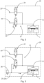
- FIG. 2 shows a section of a first embodiment of a compressed air brake system 20 with a schematic representation of the diaphragm valve 1 and a pilot switching device 21 of the diaphragm valve 1.
- the pilot control switching device 21 has a first valve device 22 and a second valve device 24 .
- the pilot control switching device 21 is designed to provide a predetermined pilot control pressure at the pilot control input 10 .
- the first valve device 22 is connected to a first compressed air source 23 at a first connection, and the first valve device 22 is connected to the pilot control input 10 of the diaphragm valve 1 at a second connection, with the first valve device 22 being designed to have the first connection and the second connection to connect and disconnect.
- the first valve device 22 has a 3/2-way valve. In an alternative embodiment, the first valve device 22 has a 2/2-way valve or another suitable valve.
- the second valve device 24 is connected to a second compressed air source 23 ′ at a first connection and the second valve device 24 is connected to the pilot control input 10 of the diaphragm valve 1 and the second connection of the first valve device 22 at a second connection.
- the second valve device 24 has a 2/2-way valve. In an alternative embodiment, the second valve device 24 has a 3/2-way valve or another suitable valve.
- the compressed air brake system 20 is designed to provide an input pressure for the second valve device 24 through the second compressed air source 23 ′ that is greater than an input pressure of the first valve device 22 that is provided by the first compressed air source 23 .
- the pressure provided by the first compressed air source 23 is 4 bar and the pressure provided by the second compressed air source 23' is 7 bar.
- the pressures can also assume other values, the pressure provided by the first compressed air source 23 can be higher than the pressure provided by the second compressed air source 23', or the pressures provided by the first compressed air source 23 and by the second compressed air source 23' can be the same .
- FIG 3 shows a detail of a second embodiment of the compressed air brake system 20 with the schematic representation of the membrane valve 1 and the pilot switching device 21 for the membrane valve 1, which is connected to a brake line 25 of a brake cylinder 26.
- the second embodiment differs from the first embodiment in that the first connection of the first valve device 22 is connected to the brake line 25 . As shown by arrows, the brake cylinder 26 is vented through the brake line 25 as long as the diaphragm valve 1 is open. If a corresponding pressure is present, the brake line 25 can act as the first pressure source 23 .
- the elastomer membrane 5 is pressed upwards by the closure member 6, so that the membrane valve 1 is open.
- the elastomer membrane 5 is pressed down.
- the membrane valve 1 is thereby closed by means of the closure member 6 .
- the membrane valve 1 can only be controlled by the first valve device 22 . According to the invention, however, the membrane valve 1 is controlled in such a way that a pilot pressure at the pilot input 10 of the membrane valve 1 by opening the first valve device 22 and by opening the second Valve device 24 is applied and thereby the diaphragm valve 1 is closed. If necessary, the pilot pressure is reduced by shutting off the first valve device 22 and by shutting off the second valve device 24, as a result of which the diaphragm valve 1 is opened. In the case of the 3/2-way valves, the shutting off interrupts the supply of compressed air to the diaphragm valve 1 and the line leading to the pilot control input 10 is vented via the valve.
- the opening of the second valve device 24 provides a higher pilot control pressure than when the first valve device 22 is opened at the pilot control inlet 10 .
- the same pilot pressure is provided at the pilot input 10 .
- the second valve device 24, which provides the higher pilot control pressure at the pilot control input 10, is only opened when a predetermined condition is present. For example, when the first valve device 22 is opened, the second valve device 24 is opened briefly in order to achieve a desired short reaction time for closing the membrane valve 1, which can be desirable in the case of anti-skid regulations. In the case in which the short reaction time is not necessary, a simultaneous opening of the second valve device 24 can be dispensed with. Alternatively, the second valve device 24 always opens at the same time as the first valve device 22.
- the second valve device 24 is closed before the first valve device 22 . This can prevent the membrane 5 from being pressed with great force onto the ring-like support contour 8 by the higher pilot pressure applied by the second valve device 24, with increased wear of the membrane 5 being prevented.
- the higher pressure provided by the second valve device 24 can also be provided in the brake line 25 . Due to this higher pressure, which then occurs both in the brake line 25 and in the pilot control input 10 is present, the pressure in the brake line 25, and thus a braking effect can be controlled very precisely.
Landscapes
- Engineering & Computer Science (AREA)
- Transportation (AREA)
- Mechanical Engineering (AREA)
- Physics & Mathematics (AREA)
- Fluid Mechanics (AREA)
- Valves And Accessory Devices For Braking Systems (AREA)
- Regulating Braking Force (AREA)
- Braking Systems And Boosters (AREA)
Abstract
Description
- Die Erfindung betrifft eine Druckluftbremsanlage für ein Fahrzeug und ein Verfahren zum Betreiben der Druckluftbremsanlage, insbesondere eine Druckluftbremsanlage mit einem Membranventil.
- Ein Einsatz von Membranventilen, insbesondere als ABS- oder Gleitschutzventile in Fahrzeugen, ist im Stand der Technik bekannt.
- Ein erwünschtes schnelles und genaues Schaltverhalten der Membranventile ist jedoch nicht einfach erzielbar, da es aufgrund einer systembedingten Trägheit der Druckluftbremsanlage nur schwer möglich ist, das Membranventil für genauere Schaltzeiten und eine genauere Festlegung eines Ausgangsdrucks des Membranventils anzusteuern.
- Daher ergibt sich die der Erfindung zugrunde liegende Aufgabe, eine Druckluftbremsanlage für ein Fahrzeug derart weiterzubilden, dass genauere Schaltzeiten und eine genauere Festlegung eines Ausgangsdrucks eines Membranventils der Druckluftbremsanlage möglich sind.
- Die Aufgabe wird durch eine Druckluftbremsanlage gemäß Anspruch 1 und ein Verfahren gemäß Anspruch 10 gelöst. Vorteilhafte Weiterentwicklungen sind in den abhängigen Ansprüchen enthalten.
- Gemäß einem Aspekt der Erfindung hat eine Druckluftbremsanlage für ein Fahrzeug ein Membranventil und eine Vorsteuerschaltvorrichtung des Membranventils, wobei die Vorsteuerschaltvorrichtung eine erste Ventileinrichtung aufweist, die an einem ersten Anschluss mit einer ersten Druckluftquelle verbindbar ist und an einem zweiten Anschluss mit einem Vorsteuereingang des Membranventils verbunden ist, wobei die erste Ventileinrichtung dazu ausgebildet ist, ihren ersten Anschluss und ihren zweiten Anschluss zu verbinden und zu trennen, und die Vorsteuerschaltvorrichtung dazu ausgebildet ist, einen vorbestimmten Vorsteuerdruck an dem Vorsteuereingang bereitzustellen, und wobei die Vorsteuerschaltvorrichtung eine zweite Ventileinrichtung aufweist, die an einem ersten Anschluss mit einer zweiten Druckluftquelle verbunden ist und an einem zweiten Anschluss mit dem Vorsteuereingang verbunden ist.
- In einer solchen Druckluftbremsanlage ist mittels dieser Vorsteuerschaltvorrichtung eine größere Variabilität der Ansteuerung hinsichtlich eines Druckverlaufs möglich. Durch die Verwendung der zweiten Ventileinrichtung kann beispielsweise ein Luftstrom zu dem Vorsteuereingang des Membranventils erhöht werden, um eine Reaktionszeit des Membranventils zu verringern ohne dass übermäßig große Ventile mit einem hohen Luftdurchsatz verwendet werden müssen.
- Gemäß einer vorteilhaften Weiterentwicklung der Druckluftbremsanlage weist die erste Ventileinrichtung ein 3/2-Wege-Ventil auf.
- Das 3/2-Wege-Ventil der ersten Ventileinrichtung ermöglicht es, den Vorsteuereingang des Membranventils mit einem vorgegebenen Druck zu beaufschlagen sowie den Vorsteuerdruck durch Entlüften über das 3/2-Wege-Ventil wieder zu verringern, um das Membranventil wunschgemäß anzusteuern.
- In einer anderen vorteilhaften Weiterentwicklung der Druckluftbremsanlage weist die erste Ventileinrichtung ein 2/2-Wege-Ventil auf.
- Der Einsatz eines solchen Ventils kann erfolgen, wenn beispielsweise die Möglichkeit besteht, Luft über eine Öffnung in der Membran des Membranventils abströmen zu lassen. Dadurch kann der Vorsteuerdruck verringert werden wenn das 2/2-Wege-Ventil geschlossen wird. In diesem Fall bietet das 2/2-Wege-Ventil eine kostengünstige und einfache Möglichkeit, das Membranventil anzusteuern.
- Bei einer weiteren vorteilhaften Ausgestaltung der Druckluftbremsanlage weist die zweite Ventileinrichtung ein 2/2-Wege-Ventil auf.
- Die zweite Ventileinrichtung mit dem 2/2-Wege-Ventil bietet eine kostengünstige Möglichkeit, einen Volumenstrom der Luft zu dem Vorsteuereingang des Membranventils zu erhöhen, um eine Reaktionszeit hinsichtlich des Schließens des Membranventils zu verringern.
- Gemäß einer anderen vorteilhaften Ausgestaltung der Druckluftbremsanlage weist die zweite Ventileinrichtung ein 3/2-Wege-Ventil auf.
- Durch den Einsatz des 3/2-Wege-Ventils der zweiten Ventileinrichtung kann der Vorsteuerdruck, verglichen mit einer bloßen Verwendung des 3/2-Wege-Ventils der ersten Ventileinrichtung oder des bloßen Abströmens der Luft über die Öffnung in der Membran schneller verringert werden, um so die Reaktionszeit des Membranventils beim Öffnen zu verkürzen, ohne dass übermäßig große Ventile mit einem hohen Luftdurchsatz verwendet werden müssen.
- Entsprechend einer weiteren vorteilhaften Ausgestaltung der Druckluftbremsanlage ist sie dazu ausgebildet, für die erste Ventileinrichtung und die zweite Ventileinrichtung durch die erste und zweite Druckluftquelle gleiche Eingangsdrücke bereitzustellen.
- Durch das Bereitstellen von gleichen Eingangsdrücken ist es nicht nötig, unterschiedliche Druckregler für die Vorsteuerschaltvorrichtung vorzusehen, wobei dennoch ein Luftstrom zu dem Vorsteuereingang erhöht werden kann, um eine Reaktionszeit des Membranventils zu verringern.
- In einer anderen vorteilhaften Ausgestaltung der Druckluftbremsanlage ist sie dazu ausgebildet, für die erste und die zweite Ventileinrichtung durch die erste und zweite Druckluftquelle unterschiedliche Eingangsdrücke bereitzustellen.
- Durch das Bereitstellen der unterschiedlichen Drücke besteht die Möglichkeit, in Abhängigkeit von dem momentanen Betriebszustand, ein unterschiedliches Verhalten des Membranventils zu erzielen.
- In einer vorteilhaften Ausgestaltung der Druckluftbremsanlage ist ein Eingangsdruck der zweiten Ventileinrichtung größer als ein Eingangsdruck der ersten Ventileinrichtung.
- Durch diese Eigenschaft ist es möglich, beispielsweise in einem sogenannten Normalbetrieb den Vorsteuereingang lediglich mit einem geringeren Druck durch die erste Ventileinrichtung zu beaufschlagen, jedoch unter bestimmten Bedingungen, bei denen eine kürzere Reaktionszeit des Membranventils erforderlich ist, einen höheren Vorsteuerdruck durch die zweite Ventileinrichtung bereitzustellen.
- Bei einer weiteren vorteilhaften Ausgestaltung der Druckluftbremsanlage ist ein Eingang des Membranventils über eine Bremsleitung mit einem Bremszylinder so verbunden, dass das Membranventil dazu ausgebildet ist, den Bremszylinder über die Bremsleitung zu entlüften, und der erste Anschluss der ersten Ventileinrichtung ist mit der Bremsleitung verbunden.
- Durch diese Ausgestaltung ist es möglich, ohne einen Einsatz von weiteren Komponenten zusätzlich den Druck in der Bremsleitung und daher in dem Bremszylinder zu erhöhen, um eine sehr genaue Bremswirkung einzustellen.
- Gemäß einem weiteren Aspekt der Erfindung weist ein Verfahren zum Betreiben einer Druckluftbremsanlage die Schritte auf: Anlegen eines Vorsteuerdrucks an dem Vorsteuereingang des Membranventils mittels eines Öffnens der ersten Ventileinrichtung und mittels eines Öffnens der zweiten Ventileinrichtung wodurch das Membranventil geschlossen wird und Verringern des Vorsteuerdrucks mittels eines Absperrens der ersten Ventileinrichtung und mittels eines Absperrens der zweiten Ventileinrichtung wodurch das Membranventil geöffnet wird.
- Durch diese Schritte ist es möglich, einen Luftstrom zu dem Vorsteuereingang des Membranventils zu erhöhen, um eine Reaktionszeit des Membranventils zu verringern, ohne dass übermäßig große Ventile mit einem hohen Luftdurchsatz verwendet werden müssen.
- Entsprechend einer vorteilhaften Ausgestaltung des Verfahrens wird durch das Öffnen der zweiten Ventileinrichtung ein höherer Vorsteuerdruck als bei dem Öffnen der ersten Ventileinrichtung bereitgestellt.
- Durch die Bereitstellung des höheren Vorsteuerdrucks kann ein rascheres Schließen des Membranventils erzielt werden, da bei einer identischen Membranfläche eine größere Kraft vorhanden ist, sodass notwendige Schaltdrücke schneller erreicht werden.
- Bei einer weiteren vorteilhaften Ausgestaltung des Verfahrens wird die zweite Ventileinrichtung nur bei Vorliegen einer vorbestimmten Bedingung geöffnet.
- Im Normalbetrieb wird der Vorsteuereingang lediglich mit dem geringeren Druck durch die erste Ventileinrichtung beaufschlagt, jedoch wird unter bestimmten Bedingungen, bei denen eine kürzere Reaktionszeit des Membranventils erforderlich ist, der höhere Vorsteuerdruck durch die zweite Ventileinrichtung bereitgestellt, so dass das Ventil schneller geschlossen werden kann.
- In einer weiteren vorteilhaften Ausgestaltung des Verfahrens wird die zweite Ventileinrichtung vor der ersten Ventileinrichtung geschlossen.
- Durch diese Eigenschaft ist es möglich, das Membranventil rasch zu schließen, jedoch, da die Ventileinrichtung, die einen höheren Vorsteuerdruck bereitstellt, geschlossen wird, eine Kraft, mit der die Membran an eine Anschlagfläche gepresst wird, zu verringern um eine Lebensdauer der Membran zu erhöhen.
- Bei einer weiteren vorteilhaften Ausgestaltung des Verfahrens wird der größere Eingangsdruck sowohl in dem Vorsteuereingang als auch in der Bremsleitung und an dem Eingang des Membranventils bereitgestellt.
- Durch eine solche Bereitstellung ist es möglich, ohne einen Einsatz von weiteren Komponenten auch den Druck in der Bremsleitung zu erhöhen, um eine sehr genaue Druckregelung und somit sehr genaue Bremswirkung einzustellen.
- Nachverfolgend wird die Erfindung anhand von Ausführungsformen und Bezugnahme auf die beigefügte Zeichnung erläutert.
- Insbesondere zeigt
- Fig. 1
- einen Querschnitt eines Oberteils eines Membranventils;
- Fig. 2
- einen Ausschnitt einer ersten Ausführungsform einer Druckluftbremsanlage mit einer Prinzipdarstellung des Membranventils und einer Vorsteuerschaltvorrichtung für das Membranventil; und
- Fig. 3
- einen Ausschnitt einer zweiten Ausführungsform der Druckluftbremsanlage mit der Prinzipdarstellung des Membranventils und der Vorsteuerschaltvorrichtung für das Membranventil, die mit einer Bremsleitung eines Bremszylinders verbunden ist.
-
Fig. 1 zeigt einen Querschnitt eines Oberteils eines Membranventils 1. - Das Membranventil 1 weist ein Ventilgehäuse 2 auf, das im Bereich einer Steuerdruckkammer 3 mit einem Gehäusedeckel 4 verbunden ist. Zwischen dem Ventilgehäuse 2 und dem Gehäusedeckel 4 ist eine Elastomermembran 5 zur Betätigung eines hiervon angetriebenen Verschlussglieds 6 angeordnet.
- Auf der Seite der unteren Membranfläche 7 der Elastomermembran 5 ist eine ringartige Stützkontur 8 vorgesehen, die durch einen formschlüssig in das Ventilgehäuse 2 eingelegten Stützring 9 gebildet ist.
- In dem Gehäusedeckel 4 ist ferner ein Vorsteuereingang 10 des Membranventils 1 zur Zuführung eines Steuerdrucks für das Membranventil 1 vorgesehen. Das Membranventil 1 kann in alternativen Ausführungsformen auch einen anderen Aufbau aufweisen, wobei die Funktionselemente, wie etwa die Elastomermembran 5 und das Verschlussglied, vorhanden sind und entsprechend funktionieren.
-
Fig. 2 zeigt einen Ausschnitt einer ersten Ausführungsform einer Druckluftbremsanlage 20 mit einer Prinzipdarstellung des Membranventils 1 und einer Vorsteuerschaltvorrichtung 21 des Membranventils 1. - Die Vorsteuerschaltvorrichtung 21 weist eine erste Ventileinrichtung 22 und eine zweite Ventileinrichtung 24 auf. Die Vorsteuerschaltvorrichtung 21 ist dazu ausgebildet, einen vorbestimmten Vorsteuerdruck an dem Vorsteuereingang 10 bereitzustellen.
- Die erste Ventileinrichtung 22 ist an einem ersten Anschluss mit einer ersten Druckluftquelle 23 verbunden und an einem zweiten Anschluss ist die erste Ventileinrichtung 22 mit dem Vorsteuereingang 10 des Membranventils 1 verbunden, wobei die erste Ventileinrichtung 22 dazu ausgebildet ist, den ersten Anschluss und den zweiten Anschluss zu verbinden und zu trennen. Die erste Ventileinrichtung 22 weist ein 3/2-Wege-Ventil auf. In einer alternativen Ausführungsform weist die erste Ventileinrichtung 22 ein 2/2-Wege-Ventil oder ein anderes geeignetes Ventil auf.
- Die zweite Ventileinrichtung 24 ist an einem ersten Anschluss mit einer zweiten Druckluftquelle 23' verbunden und an einem zweiten Anschluss ist die zweite Ventileinrichtung 24 mit dem Vorsteuereingang 10 des Membranventils 1 und dem zweiten Anschluss der ersten Ventileinrichtung 22 verbunden. Die zweite Ventileinrichtung 24 weist ein 2/2-Wege-Ventil auf. In einer alternativen Ausführungsform weist die zweite Ventileinrichtung 24 ein 3/2-Wege-Ventil oder ein anderes geeignetes Ventil auf.
- Die Druckluftbremsanlage 20 ist dazu ausgebildet, für die zweite Ventileinrichtung 24 durch die zweite Druckluftquelle 23' einen Eingangsdruck bereitzustellen, der größer als ein Eingangsdruck der ersten Ventileinrichtung 22 ist, der durch die erste Druckluftquelle 23 bereitgestellt wird. In dieser Ausführungsform beträgt der durch die erste Druckluftquelle 23 bereitgestellte Druck 4 bar und der durch die zweite Druckluftquelle 23' bereitgestellte Druck beträgt 7 bar. In alternativen Ausführungsformen können die Drücke auch andere Werte annehmen, der durch die erste Druckluftquelle 23 bereitgestellte Druck kann höher als der durch die zweite Druckluftquelle 23' bereitgestellte Druck sein, oder die durch die erste Druckluftquelle 23 und durch die zweite Druckluftquelle 23' bereitgestellten Drücke können gleich sein.
-
Fig. 3 zeigt einen Ausschnitt einer zweiten Ausführungsform der Druckluftbremsanlage 20 mit der Prinzipdarstellung des Membranventils 1 und der Vorsteuerschaltvorrichtung 21 für das Membranventil 1, die mit einer Bremsleitung 25 eines Bremszylinders 26 verbunden ist. - Die zweite Ausführungsform unterscheidet sich von der ersten Ausführungsform darin, dass der erste Anschluss der ersten Ventileinrichtung 22 mit der Bremsleitung 25 verbunden ist. Durch die Bremsleitung 25 wird, wie durch Pfeile gezeigt ist, der Bremszylinder 26 entlüftet solange das Membranventil 1 geöffnet ist. Bei einem Vorliegen eines entsprechenden Drucks kann die Bremsleitung 25 als erste Druckquelle 23 wirken.
- Außerdem besteht bei einem Bereitstellen eines größeren Drucks durch die zweite Druckquelle 23' die Möglichkeit, auch den Druck in der Bremsleitung 25 mittels der der ersten Ventileinrichtung 22 und der zweiten Ventileinrichtung 24 zu erhöhen, um eine sehr genaue Druckregelung in der Bremsleitung 25 zu ermöglichen.
- Im Betrieb wird, wenn kein Vorsteuerdruck in der Steuerdruckkammer 3 vorhanden ist, die Elastomermembran 5 durch das Verschlussglied 6 nach oben gedrückt, sodass das Membranventil 1 geöffnet ist. Durch ein Einbringen des Vorsteuerdrucks über den Vorsteuereingang 10 in die Steuerdruckkammer 3 wird die Elastomermembran 5 nach unten gedrückt. Dabei wird das Membranventil 1 mittels des Verschlussglieds 6 geschlossen.
- Das Membranventil 1 kann nur durch die erste Ventileinrichtung 22 angesteuert werden. Erfindungsgemäß wird jedoch das Membranventil 1 derart angesteuert, dass ein Vorsteuerdruck an dem Vorsteuereingang 10 des Membranventils 1 mittels eines Öffnens der ersten Ventileinrichtung 22 und mittels eines Öffnens der zweiten Ventileinrichtung 24 angelegt wird und dadurch das Membranventil 1 geschlossen wird. Bei Bedarf wird der Vorsteuerdruck mittels eines Absperrens der ersten Ventileinrichtung 22 und mittels eines Absperrens der zweiten Ventileinrichtung 24 verringert, wodurch das Membranventil 1 geöffnet wird. Durch das Absperren wird im Fall der 3/2-Wege-Ventile die Versorgung des Membranventils 1 mit Druckluft unterbrochen und die zu dem Vorsteuereingang 10 führende Leitung über das Ventil entlüftet.
- Durch das Öffnen der zweiten Ventileinrichtung 24 wird ein höherer Vorsteuerdruck als beim Öffnen der ersten Ventileinrichtung 22 an dem Vorsteuereingang 10 bereitgestellt. Alternativ wird ein gleicher Vorsteuerdruck an dem Vorsteuereingang 10 bereitgestellt.
- Die zweite Ventileinrichtung 24, die den höheren Vorsteuerdruck an dem Vorsteuereingang 10 bereitstellt, wird nur bei einem Vorliegen einer vorbestimmten Bedingung geöffnet. Beispielsweise wird bei dem Öffnen der ersten Ventileinrichtung 22 die zweite Ventileinrichtung 24 kurz geöffnet, um eine gewünschte kurze Reaktionszeit zum Schließen des Membranventils 1 zu erreichen, was bei Gleitschutzregelungen gewünscht sein kann. In dem Fall, in dem die kurze Reaktionszeit nicht notwendig ist, kann auf ein zeitgleiches Öffnen der zweiten Ventileinrichtung 24 verzichtet werden. Alternativ öffnet die zweite Ventileinrichtung 24 immer gleichzeitig mit der ersten Ventileinrichtung 22.
- Die zweite Ventileinrichtung 24 wird vor der ersten Ventileinrichtung 22 geschlossen. Dadurch kann verhindert werden, dass die Membran 5 durch den durch die zweite Ventileinrichtung 24 aufgebrachten höheren Vorsteuerdruck mit großer Kraft auf die ringartige Stützkontur 8 angepresst wird wobei ein erhöhter Verschleiß der Membran 5 verhindert wird.
- Wenn der erste Anschluss der ersten Ventileinrichtung 22 mit der Bremsleitung 25 verbunden ist, kann der durch die zweite Ventileinrichtung 24 bereitgestellte höhere Druck auch in der Bremsleitung 25 bereitgestellt werden. Durch diesen höheren Druck, der dann sowohl in der Bremsleitung 25 als auch in dem Vorsteuereingang 10 vorhanden ist, können der Druck in der Bremsleitung 25, und somit eine Bremswirkung sehr genau geregelt werden.
- Obwohl die vorliegende Erfindung unter Bezugnahme auf bestimmte Merkmale und Ausführungsformen beschrieben wurde, ist es offensichtlich, dass verschiedene Modifikationen und Kombinationen daran vorgenommen werden können, ohne vom Geist und Umfang der Erfindung abzuweichen. Die Beschreibung und die Zeichnungen sind dementsprechend lediglich als eine Illustration der Erfindung zu betrachten, wie sie durch die beigefügten Ansprüche definiert ist, und sollen alle Modifikationen, Variationen, Kombinationen oder Äquivalente abdecken, die in den Anwendungsbereich der vorliegenden Erfindung fallen.
-
- 1
- Membranventil
- 2
- Ventilgehäuse
- 3
- Steuerdruckkammer
- 4
- Gehäusedeckel
- 5
- Elastomermembran
- 6
- Verschlussglied
- 7
- untere Membranfläche
- 8
- ringartige Stützkontur
- 9
- Stützring
- 10
- Vorsteuereingang
- 20
- Druckluftbremsanlage
- 21
- Vorsteuerschaltvorrichtung
- 22
- erste Ventileinrichtung
- 23, 23'
- Druckluftquelle
- 24
- zweite Ventileinrichtung
- 25
- Bremsleitung
- 26
- Bremszylinder
- 27
- Eingang
Claims (14)
- Druckluftbremsanlage (20) für ein Fahrzeug, mit einem Membranventil (1) und einer Vorsteuerschaltvorrichtung (21) des Membranventils (1), wobei die Vorsteuerschaltvorrichtung (21) aufweist:eine erste Ventileinrichtung (22), die an einem ersten Anschluss der ersten Ventileinrichtung (22) mit einer ersten Druckluftquelle (23) verbindbar ist und an einem zweiten Anschluss der ersten Ventileinrichtung (22) mit einem Vorsteuereingang (10) des Membranventils (1) verbunden ist,wobei die erste Ventileinrichtung (22) dazu ausgebildet ist, den ersten Anschluss der ersten Ventileinrichtung (22) und den zweiten Anschluss der ersten Ventileinrichtung (22) zu verbinden und zu trennen, unddie Vorsteuerschaltvorrichtung (21) dazu ausgebildet ist, einen vorbestimmten Vorsteuerdruck an dem Vorsteuereingang (10) bereitzustellen,dadurch gekennzeichnet, dassdie Vorsteuerschaltvorrichtung (21) ferner eine zweite Ventileinrichtung (24) aufweist, die an einem ersten Anschluss der zweiten Ventileinrichtung (24) mit einer zweiten Druckluftquelle (23') verbunden ist und an einem zweiten Anschluss der zweiten Ventileinrichtung (24) mit dem zweiten Anschluss der ersten Ventileinrichtung (22) und mit dem Vorsteuereingang (10) verbunden ist.
- Druckluftbremsanlage (20) gemäß Anspruch 1, wobei
die erste Ventileinrichtung (22) ein 3/2-Wege-Ventil aufweist. - Druckluftbremsanlage (20) gemäß Anspruch 1, wobei
die erste Ventileinrichtung (22) ein 2/2-Wege-Ventil aufweist. - Druckluftbremsanlage (20) gemäß einem der vorangehenden Ansprüche, wobei
die zweite Ventileinrichtung (24) ein 2/2-Wege-Ventil aufweist. - Druckluftbremsanlage (20) gemäß einem der Ansprüche 1 bis 3, wobei
die zweite Ventileinrichtung (24) ein 3/2-Wege-Ventil aufweist. - Druckluftbremsanlage (20) gemäß einem der vorangehenden Ansprüche, wobei
die Druckluftbremsanlage (20) dazu ausgebildet ist, für die erste Ventileinrichtung (22) und die zweite Ventileinrichtung (24) durch die erste und zweite Druckluftquelle (23, 23') gleiche Eingangsdrücke bereitzustellen - Druckluftbremsanlage (20) gemäß einem der Ansprüche 1 bis 5, wobei
die Druckluftbremsanlage (20) dazu ausgebildet ist, für die erste Ventileinrichtung (22) und die zweite Ventileinrichtung (24) durch die erste und zweite Druckluftquelle (23, 23') unterschiedliche Eingangsdrücke bereitzustellen. - Druckluftbremsanlage (20) gemäß Anspruch 7, wobei ein Eingangsdruck der zweiten Ventileinrichtung (24) größer als ein Eingangsdruck der ersten Ventileinrichtung (22) ist.
- Druckluftbremsanlage (20) gemäß Anspruch 8, wobeiein Eingang (27) des Membranventils (1) über eine Bremsleitung (25) mit einem Bremszylinder (26) so verbunden ist, dass das Membranventil (1) dazu ausgebildet ist, den Bremszylinder (26) über die Bremsleitung (25) zu entlüften, undder erste Anschluss der ersten Ventileinrichtung (22) mit der Bremsleitung (25) verbunden ist.
- Verfahren zum Betreiben einer Druckluftbremsanlage (20) gemäß einem der Ansprüche 1 bis 9 mit den Schritten:Anlegen eines Vorsteuerdrucks an dem Vorsteuereingang (10) des Membranventils (1) mittels eines Öffnens der ersten Ventileinrichtung (22) und mittels eines Öffnens der zweiten Ventileinrichtung (24) wodurch das Membranventil (1) geschlossen wird; undVerringern des Vorsteuerdrucks mittels eines Absperrens der ersten Ventileinrichtung (22) und mittels eines Absperrens der zweiten Ventileinrichtung (24) wodurch das Membranventil (1) geöffnet wird.
- Verfahren gemäß Anspruch 10, wobei
durch das Öffnen der zweiten Ventileinrichtung (24) ein höherer Vorsteuerdruck als bei beim Öffnen der ersten Ventileinrichtung (22) bereitgestellt wird. - Verfahren gemäß Anspruch 10 oder 11, wobei
die zweite Ventileinrichtung (24) nur bei Vorliegen einer vorbestimmten Bedingung geöffnet wird. - Verfahren gemäß Anspruch 11 oder 12, wobei
die zweite Ventileinrichtung (24) vor der ersten Ventileinrichtung (22) geschlossen wird. - Verfahren gemäß einem der Ansprüche 10 bis 13 mit einer Druckluftversorgungsanlage gemäß Anspruch 9, wobei
der größere Eingangsdruck sowohl in dem Vorsteuereingang (10) als auch in der Bremsleitung (25) und an dem Bremseingang (27) des Membranventils (1) bereitgestellt wird.
Applications Claiming Priority (1)
| Application Number | Priority Date | Filing Date | Title |
|---|---|---|---|
| DE102022100611.5A DE102022100611A1 (de) | 2022-01-12 | 2022-01-12 | Druckluftbremsanlage für ein Fahrzeug und Verfahren zum Betreiben der Druckluftbremsanlage |
Publications (2)
| Publication Number | Publication Date |
|---|---|
| EP4212399A1 true EP4212399A1 (de) | 2023-07-19 |
| EP4212399B1 EP4212399B1 (de) | 2024-10-30 |
Family
ID=84820039
Family Applications (1)
| Application Number | Title | Priority Date | Filing Date |
|---|---|---|---|
| EP23150298.0A Active EP4212399B1 (de) | 2022-01-12 | 2023-01-04 | Druckluftbremsanlage für ein fahrzeug und verfahren zum betreiben der druckluftbremsanlage |
Country Status (4)
| Country | Link |
|---|---|
| EP (1) | EP4212399B1 (de) |
| CN (1) | CN116424293B (de) |
| DE (1) | DE102022100611A1 (de) |
| ES (1) | ES3000065T3 (de) |
Citations (4)
| Publication number | Priority date | Publication date | Assignee | Title |
|---|---|---|---|---|
| FR1445292A (fr) * | 1965-08-25 | 1966-07-08 | Bosch Gmbh Robert | Installation de freinage par fluide sous pression |
| FR2009006A1 (de) * | 1968-05-21 | 1970-01-30 | Knorr Bremse Gmbh | |
| RU2185978C1 (ru) * | 2000-11-29 | 2002-07-27 | Борисов Петр Павлович | Электропневматический модулятор давления с ускорительным клапаном |
| DE10245916A1 (de) * | 2002-10-01 | 2004-04-15 | Wabco Gmbh & Co. Ohg | Bremsdruckmodulator |
Family Cites Families (6)
| Publication number | Priority date | Publication date | Assignee | Title |
|---|---|---|---|---|
| JP3814164B2 (ja) * | 2000-06-28 | 2006-08-23 | ウエスチングハウス・エヤー・ブレーキ・テクノロジーズ・コーポレイション | 鉄道車両用の段階解除弁及びブレーキ圧力の段階解除を行うために鉄道車両のブレーキを制御する方法 |
| DE102008026028A1 (de) * | 2008-05-30 | 2009-12-03 | Knorr-Bremse Systeme für Nutzfahrzeuge GmbH | Kompressorsystem und Verfahren zum Betreiben eines Kompressorsystems |
| DE102010010606B4 (de) * | 2010-03-08 | 2015-02-19 | Knorr-Bremse Systeme für Nutzfahrzeuge GmbH | Modular aufgebaute Drucksteuervorrichtung einer Druckmittel-Bremsanlage eines Fahrzeugs |
| DE102017008184A1 (de) | 2017-08-31 | 2019-02-28 | Wabco Gmbh | Parkbrems-Ventileinrichtung |
| DE102018215295A1 (de) * | 2018-09-07 | 2020-03-12 | Knorr-Bremse Systeme für Schienenfahrzeuge GmbH | Verteilte Reglerstruktur zur Erzielung optimierter Reglereigenschaften sowie erhöhter Ventillebensdauer |
| CN109835319B (zh) * | 2019-03-12 | 2020-12-22 | 中车资阳机车有限公司 | 一种空气系统增压制动装置 |
-
2022
- 2022-01-12 DE DE102022100611.5A patent/DE102022100611A1/de active Pending
-
2023
- 2023-01-04 EP EP23150298.0A patent/EP4212399B1/de active Active
- 2023-01-04 ES ES23150298T patent/ES3000065T3/es active Active
- 2023-01-10 CN CN202310031276.5A patent/CN116424293B/zh active Active
Patent Citations (4)
| Publication number | Priority date | Publication date | Assignee | Title |
|---|---|---|---|---|
| FR1445292A (fr) * | 1965-08-25 | 1966-07-08 | Bosch Gmbh Robert | Installation de freinage par fluide sous pression |
| FR2009006A1 (de) * | 1968-05-21 | 1970-01-30 | Knorr Bremse Gmbh | |
| RU2185978C1 (ru) * | 2000-11-29 | 2002-07-27 | Борисов Петр Павлович | Электропневматический модулятор давления с ускорительным клапаном |
| DE10245916A1 (de) * | 2002-10-01 | 2004-04-15 | Wabco Gmbh & Co. Ohg | Bremsdruckmodulator |
Also Published As
| Publication number | Publication date |
|---|---|
| CN116424293B (zh) | 2025-09-12 |
| EP4212399B1 (de) | 2024-10-30 |
| CN116424293A (zh) | 2023-07-14 |
| DE102022100611A1 (de) | 2023-07-13 |
| ES3000065T3 (en) | 2025-02-27 |
Similar Documents
| Publication | Publication Date | Title |
|---|---|---|
| EP2379385B1 (de) | Kombiniertes druckbegrenzungs- und überströmerventil | |
| EP3737594B1 (de) | Vorrichtung und verfahren zur realisierung kontrollierter reaktionen bei einer systemstörung | |
| EP3286053B1 (de) | Parkbremseinrichtung für kraftfahrzeuge | |
| EP2731839A2 (de) | Druckluftaufbereitungsanlage und verfahren zum betreiben einer druckluftaufbereitungsanlage | |
| EP3371019A1 (de) | Druckbegrenzungsventil | |
| DE2008025A1 (de) | Hydraulische Bremseinrichtung für Fahrzeuge | |
| DE3124154A1 (de) | Unterdrucksystem zur betaetigungskraftverstaerkung in kraftfahrzeugen | |
| EP1519866B1 (de) | Beatmungseinrichtung für einen bremszylinder | |
| EP3686074B1 (de) | Mehrkreisschutzventil einer druckluftanlage | |
| EP1361131A1 (de) | Druckluftaufbereitungseinrichtung für Kfz-Druckluftanlagen | |
| DE102011107490B4 (de) | Mehrkreisschutzventil, Belüftungsverfahren,Luftaufbereitungseinrichtung, Druckluftanlage und Fahrzeug zum Belüften mehrerer entlüfteter Druckkreise in einer definierten Auffüllreihenfolge | |
| EP0289712B1 (de) | Druckregelventil | |
| EP1633613A1 (de) | Bremsvorrichtung eines schienenfahrzeugs | |
| DE3127775A1 (de) | "betriebsbremsbeschleuniger fuer schienenfahrzeug-druckluftbremsanlagen" | |
| DE102015106144A1 (de) | Steuerventileinrichtung für eine Parkbremseinrichtung für Kraftfahrzeuge sowie Parkbremseinrichtung für Kraftfahrzeuge | |
| DE10139773A1 (de) | Steuervorrichtung für Druckluftbremsen | |
| EP4212399B1 (de) | Druckluftbremsanlage für ein fahrzeug und verfahren zum betreiben der druckluftbremsanlage | |
| DE102022111889B3 (de) | Steuerluftsystem für einen hydrodynamischen Retarder | |
| EP0105117B1 (de) | Pulsierend arbeitende Bremsbeschleuniger-Einrichtung für eine indirekt wirkende Druckluftbremse für Schienenfahrzeuge | |
| DE19701200A1 (de) | Drucksteuerventil | |
| DE102020114601A1 (de) | Steuerluftsystem für einen hydrodynamischen Retarder | |
| DE2254655A1 (de) | Anpassender bremskraftregler fuer druckluftgebremste fahrzeuge | |
| DE2423430A1 (de) | Steuerventil fuer druckluftbremsen, insbesondere fuer schienenfahrzeuge | |
| EP0600178A2 (de) | Anhänger-Steuerventil | |
| EP0026504B1 (de) | Absenkeinrichtung einer Führerbremsventilanlage für indirekt wirkende Druckluftbremsen von Schienenfahrzeugen |
Legal Events
| Date | Code | Title | Description |
|---|---|---|---|
| PUAI | Public reference made under article 153(3) epc to a published international application that has entered the european phase |
Free format text: ORIGINAL CODE: 0009012 |
|
| STAA | Information on the status of an ep patent application or granted ep patent |
Free format text: STATUS: THE APPLICATION HAS BEEN PUBLISHED |
|
| AK | Designated contracting states |
Kind code of ref document: A1 Designated state(s): AL AT BE BG CH CY CZ DE DK EE ES FI FR GB GR HR HU IE IS IT LI LT LU LV MC ME MK MT NL NO PL PT RO RS SE SI SK SM TR |
|
| STAA | Information on the status of an ep patent application or granted ep patent |
Free format text: STATUS: REQUEST FOR EXAMINATION WAS MADE |
|
| 17P | Request for examination filed |
Effective date: 20240119 |
|
| RBV | Designated contracting states (corrected) |
Designated state(s): AL AT BE BG CH CY CZ DE DK EE ES FI FR GB GR HR HU IE IS IT LI LT LU LV MC ME MK MT NL NO PL PT RO RS SE SI SK SM TR |
|
| GRAP | Despatch of communication of intention to grant a patent |
Free format text: ORIGINAL CODE: EPIDOSNIGR1 |
|
| STAA | Information on the status of an ep patent application or granted ep patent |
Free format text: STATUS: GRANT OF PATENT IS INTENDED |
|
| INTG | Intention to grant announced |
Effective date: 20240618 |
|
| GRAS | Grant fee paid |
Free format text: ORIGINAL CODE: EPIDOSNIGR3 |
|
| GRAA | (expected) grant |
Free format text: ORIGINAL CODE: 0009210 |
|
| STAA | Information on the status of an ep patent application or granted ep patent |
Free format text: STATUS: THE PATENT HAS BEEN GRANTED |
|
| AK | Designated contracting states |
Kind code of ref document: B1 Designated state(s): AL AT BE BG CH CY CZ DE DK EE ES FI FR GB GR HR HU IE IS IT LI LT LU LV MC ME MK MT NL NO PL PT RO RS SE SI SK SM TR |
|
| REG | Reference to a national code |
Ref country code: GB Ref legal event code: FG4D Free format text: NOT ENGLISH |
|
| REG | Reference to a national code |
Ref country code: CH Ref legal event code: EP |
|
| REG | Reference to a national code |
Ref country code: DE Ref legal event code: R096 Ref document number: 502023000234 Country of ref document: DE |
|
| REG | Reference to a national code |
Ref country code: IE Ref legal event code: FG4D Free format text: LANGUAGE OF EP DOCUMENT: GERMAN |
|
| REG | Reference to a national code |
Ref country code: SE Ref legal event code: TRGR |
|
| P01 | Opt-out of the competence of the unified patent court (upc) registered |
Free format text: CASE NUMBER: APP_66680/2024 Effective date: 20241217 |
|
| REG | Reference to a national code |
Ref country code: LT Ref legal event code: MG9D |
|
| REG | Reference to a national code |
Ref country code: ES Ref legal event code: FG2A Ref document number: 3000065 Country of ref document: ES Kind code of ref document: T3 Effective date: 20250227 |
|
| REG | Reference to a national code |
Ref country code: NL Ref legal event code: MP Effective date: 20241030 |
|
| PG25 | Lapsed in a contracting state [announced via postgrant information from national office to epo] |
Ref country code: IS Free format text: LAPSE BECAUSE OF FAILURE TO SUBMIT A TRANSLATION OF THE DESCRIPTION OR TO PAY THE FEE WITHIN THE PRESCRIBED TIME-LIMIT Effective date: 20250228 Ref country code: HR Free format text: LAPSE BECAUSE OF FAILURE TO SUBMIT A TRANSLATION OF THE DESCRIPTION OR TO PAY THE FEE WITHIN THE PRESCRIBED TIME-LIMIT Effective date: 20241030 Ref country code: PT Free format text: LAPSE BECAUSE OF FAILURE TO SUBMIT A TRANSLATION OF THE DESCRIPTION OR TO PAY THE FEE WITHIN THE PRESCRIBED TIME-LIMIT Effective date: 20250228 |
|
| PG25 | Lapsed in a contracting state [announced via postgrant information from national office to epo] |
Ref country code: FI Free format text: LAPSE BECAUSE OF FAILURE TO SUBMIT A TRANSLATION OF THE DESCRIPTION OR TO PAY THE FEE WITHIN THE PRESCRIBED TIME-LIMIT Effective date: 20241030 Ref country code: NL Free format text: LAPSE BECAUSE OF FAILURE TO SUBMIT A TRANSLATION OF THE DESCRIPTION OR TO PAY THE FEE WITHIN THE PRESCRIBED TIME-LIMIT Effective date: 20241030 |
|
| PG25 | Lapsed in a contracting state [announced via postgrant information from national office to epo] |
Ref country code: BG Free format text: LAPSE BECAUSE OF FAILURE TO SUBMIT A TRANSLATION OF THE DESCRIPTION OR TO PAY THE FEE WITHIN THE PRESCRIBED TIME-LIMIT Effective date: 20241030 |
|
| PG25 | Lapsed in a contracting state [announced via postgrant information from national office to epo] |
Ref country code: NO Free format text: LAPSE BECAUSE OF FAILURE TO SUBMIT A TRANSLATION OF THE DESCRIPTION OR TO PAY THE FEE WITHIN THE PRESCRIBED TIME-LIMIT Effective date: 20250130 |
|
| PG25 | Lapsed in a contracting state [announced via postgrant information from national office to epo] |
Ref country code: GR Free format text: LAPSE BECAUSE OF FAILURE TO SUBMIT A TRANSLATION OF THE DESCRIPTION OR TO PAY THE FEE WITHIN THE PRESCRIBED TIME-LIMIT Effective date: 20250131 Ref country code: LV Free format text: LAPSE BECAUSE OF FAILURE TO SUBMIT A TRANSLATION OF THE DESCRIPTION OR TO PAY THE FEE WITHIN THE PRESCRIBED TIME-LIMIT Effective date: 20241030 |
|
| PG25 | Lapsed in a contracting state [announced via postgrant information from national office to epo] |
Ref country code: PL Free format text: LAPSE BECAUSE OF FAILURE TO SUBMIT A TRANSLATION OF THE DESCRIPTION OR TO PAY THE FEE WITHIN THE PRESCRIBED TIME-LIMIT Effective date: 20241030 |
|
| PG25 | Lapsed in a contracting state [announced via postgrant information from national office to epo] |
Ref country code: RS Free format text: LAPSE BECAUSE OF FAILURE TO SUBMIT A TRANSLATION OF THE DESCRIPTION OR TO PAY THE FEE WITHIN THE PRESCRIBED TIME-LIMIT Effective date: 20250130 |
|
| PG25 | Lapsed in a contracting state [announced via postgrant information from national office to epo] |
Ref country code: SM Free format text: LAPSE BECAUSE OF FAILURE TO SUBMIT A TRANSLATION OF THE DESCRIPTION OR TO PAY THE FEE WITHIN THE PRESCRIBED TIME-LIMIT Effective date: 20241030 |
|
| PG25 | Lapsed in a contracting state [announced via postgrant information from national office to epo] |
Ref country code: DK Free format text: LAPSE BECAUSE OF FAILURE TO SUBMIT A TRANSLATION OF THE DESCRIPTION OR TO PAY THE FEE WITHIN THE PRESCRIBED TIME-LIMIT Effective date: 20241030 |
|
| PG25 | Lapsed in a contracting state [announced via postgrant information from national office to epo] |
Ref country code: EE Free format text: LAPSE BECAUSE OF FAILURE TO SUBMIT A TRANSLATION OF THE DESCRIPTION OR TO PAY THE FEE WITHIN THE PRESCRIBED TIME-LIMIT Effective date: 20241030 |
|
| PG25 | Lapsed in a contracting state [announced via postgrant information from national office to epo] |
Ref country code: RO Free format text: LAPSE BECAUSE OF FAILURE TO SUBMIT A TRANSLATION OF THE DESCRIPTION OR TO PAY THE FEE WITHIN THE PRESCRIBED TIME-LIMIT Effective date: 20241030 |
|
| PG25 | Lapsed in a contracting state [announced via postgrant information from national office to epo] |
Ref country code: SK Free format text: LAPSE BECAUSE OF FAILURE TO SUBMIT A TRANSLATION OF THE DESCRIPTION OR TO PAY THE FEE WITHIN THE PRESCRIBED TIME-LIMIT Effective date: 20241030 |
|
| PG25 | Lapsed in a contracting state [announced via postgrant information from national office to epo] |
Ref country code: CZ Free format text: LAPSE BECAUSE OF FAILURE TO SUBMIT A TRANSLATION OF THE DESCRIPTION OR TO PAY THE FEE WITHIN THE PRESCRIBED TIME-LIMIT Effective date: 20241030 |
|
| REG | Reference to a national code |
Ref country code: DE Ref legal event code: R097 Ref document number: 502023000234 Country of ref document: DE |
|
| PLBE | No opposition filed within time limit |
Free format text: ORIGINAL CODE: 0009261 |
|
| STAA | Information on the status of an ep patent application or granted ep patent |
Free format text: STATUS: NO OPPOSITION FILED WITHIN TIME LIMIT |
|
| PG25 | Lapsed in a contracting state [announced via postgrant information from national office to epo] |
Ref country code: LU Free format text: LAPSE BECAUSE OF NON-PAYMENT OF DUE FEES Effective date: 20250104 Ref country code: MC Free format text: LAPSE BECAUSE OF FAILURE TO SUBMIT A TRANSLATION OF THE DESCRIPTION OR TO PAY THE FEE WITHIN THE PRESCRIBED TIME-LIMIT Effective date: 20241030 |
|
| 26N | No opposition filed |
Effective date: 20250731 |
|
| PG25 | Lapsed in a contracting state [announced via postgrant information from national office to epo] |
Ref country code: BE Free format text: LAPSE BECAUSE OF NON-PAYMENT OF DUE FEES Effective date: 20250131 |
|
| REG | Reference to a national code |
Ref country code: BE Ref legal event code: MM Effective date: 20250131 |
|
| PG25 | Lapsed in a contracting state [announced via postgrant information from national office to epo] |
Ref country code: IE Free format text: LAPSE BECAUSE OF NON-PAYMENT OF DUE FEES Effective date: 20250104 |
|
| PGFP | Annual fee paid to national office [announced via postgrant information from national office to epo] |
Ref country code: SE Payment date: 20260126 Year of fee payment: 4 |
|
| PGFP | Annual fee paid to national office [announced via postgrant information from national office to epo] |
Ref country code: ES Payment date: 20260210 Year of fee payment: 4 |
|
| PGFP | Annual fee paid to national office [announced via postgrant information from national office to epo] |
Ref country code: DE Payment date: 20260127 Year of fee payment: 4 |
|
| PGFP | Annual fee paid to national office [announced via postgrant information from national office to epo] |
Ref country code: AT Payment date: 20260301 Year of fee payment: 4 |
|
| PGFP | Annual fee paid to national office [announced via postgrant information from national office to epo] |
Ref country code: IT Payment date: 20260131 Year of fee payment: 4 |
|
| PGFP | Annual fee paid to national office [announced via postgrant information from national office to epo] |
Ref country code: FR Payment date: 20260126 Year of fee payment: 4 |