EP4210090B1 - Verfahren zum ausrichten und platzieren eines elektronischen bauteils und system zum ausrichten und platzieren eines elektronischen bauteils - Google Patents
Verfahren zum ausrichten und platzieren eines elektronischen bauteils und system zum ausrichten und platzieren eines elektronischen bauteils Download PDFInfo
- Publication number
- EP4210090B1 EP4210090B1 EP22151055.5A EP22151055A EP4210090B1 EP 4210090 B1 EP4210090 B1 EP 4210090B1 EP 22151055 A EP22151055 A EP 22151055A EP 4210090 B1 EP4210090 B1 EP 4210090B1
- Authority
- EP
- European Patent Office
- Prior art keywords
- electronic component
- surface side
- camera unit
- visible
- unit
- Prior art date
- Legal status (The legal status is an assumption and is not a legal conclusion. Google has not performed a legal analysis and makes no representation as to the accuracy of the status listed.)
- Active
Links
Images

Classifications
-
- H—ELECTRICITY
- H01—ELECTRIC ELEMENTS
- H01L—SEMICONDUCTOR DEVICES NOT COVERED BY CLASS H10
- H01L24/00—Arrangements for connecting or disconnecting semiconductor or solid-state bodies; Methods or apparatus related thereto
- H01L24/80—Methods for connecting semiconductor or other solid state bodies using means for bonding being attached to, or being formed on, the surface to be connected
-
- G—PHYSICS
- G06—COMPUTING OR CALCULATING; COUNTING
- G06T—IMAGE DATA PROCESSING OR GENERATION, IN GENERAL
- G06T7/00—Image analysis
- G06T7/0002—Inspection of images, e.g. flaw detection
- G06T7/0004—Industrial image inspection
- G06T7/001—Industrial image inspection using an image reference approach
-
- G—PHYSICS
- G06—COMPUTING OR CALCULATING; COUNTING
- G06T—IMAGE DATA PROCESSING OR GENERATION, IN GENERAL
- G06T7/00—Image analysis
- G06T7/70—Determining position or orientation of objects or cameras
- G06T7/73—Determining position or orientation of objects or cameras using feature-based methods
- G06T7/74—Determining position or orientation of objects or cameras using feature-based methods involving reference images or patches
-
- H—ELECTRICITY
- H01—ELECTRIC ELEMENTS
- H01L—SEMICONDUCTOR DEVICES NOT COVERED BY CLASS H10
- H01L21/00—Processes or apparatus adapted for the manufacture or treatment of semiconductor or solid state devices or of parts thereof
- H01L21/67—Apparatus specially adapted for handling semiconductor or electric solid state devices during manufacture or treatment thereof; Apparatus specially adapted for handling wafers during manufacture or treatment of semiconductor or electric solid state devices or components ; Apparatus not specifically provided for elsewhere
- H01L21/67005—Apparatus not specifically provided for elsewhere
- H01L21/67011—Apparatus for manufacture or treatment
- H01L21/67132—Apparatus for placing on an insulating substrate, e.g. tape
-
- H—ELECTRICITY
- H01—ELECTRIC ELEMENTS
- H01L—SEMICONDUCTOR DEVICES NOT COVERED BY CLASS H10
- H01L21/00—Processes or apparatus adapted for the manufacture or treatment of semiconductor or solid state devices or of parts thereof
- H01L21/67—Apparatus specially adapted for handling semiconductor or electric solid state devices during manufacture or treatment thereof; Apparatus specially adapted for handling wafers during manufacture or treatment of semiconductor or electric solid state devices or components ; Apparatus not specifically provided for elsewhere
- H01L21/67005—Apparatus not specifically provided for elsewhere
- H01L21/67011—Apparatus for manufacture or treatment
- H01L21/67144—Apparatus for mounting on conductive members, e.g. leadframes or conductors on insulating substrates
-
- H—ELECTRICITY
- H01—ELECTRIC ELEMENTS
- H01L—SEMICONDUCTOR DEVICES NOT COVERED BY CLASS H10
- H01L21/00—Processes or apparatus adapted for the manufacture or treatment of semiconductor or solid state devices or of parts thereof
- H01L21/67—Apparatus specially adapted for handling semiconductor or electric solid state devices during manufacture or treatment thereof; Apparatus specially adapted for handling wafers during manufacture or treatment of semiconductor or electric solid state devices or components ; Apparatus not specifically provided for elsewhere
- H01L21/67005—Apparatus not specifically provided for elsewhere
- H01L21/67242—Apparatus for monitoring, sorting or marking
- H01L21/67259—Position monitoring, e.g. misposition detection or presence detection
-
- H—ELECTRICITY
- H01—ELECTRIC ELEMENTS
- H01L—SEMICONDUCTOR DEVICES NOT COVERED BY CLASS H10
- H01L21/00—Processes or apparatus adapted for the manufacture or treatment of semiconductor or solid state devices or of parts thereof
- H01L21/67—Apparatus specially adapted for handling semiconductor or electric solid state devices during manufacture or treatment thereof; Apparatus specially adapted for handling wafers during manufacture or treatment of semiconductor or electric solid state devices or components ; Apparatus not specifically provided for elsewhere
- H01L21/677—Apparatus specially adapted for handling semiconductor or electric solid state devices during manufacture or treatment thereof; Apparatus specially adapted for handling wafers during manufacture or treatment of semiconductor or electric solid state devices or components ; Apparatus not specifically provided for elsewhere for conveying, e.g. between different workstations
- H01L21/67703—Apparatus specially adapted for handling semiconductor or electric solid state devices during manufacture or treatment thereof; Apparatus specially adapted for handling wafers during manufacture or treatment of semiconductor or electric solid state devices or components ; Apparatus not specifically provided for elsewhere for conveying, e.g. between different workstations between different workstations
- H01L21/67721—Apparatus specially adapted for handling semiconductor or electric solid state devices during manufacture or treatment thereof; Apparatus specially adapted for handling wafers during manufacture or treatment of semiconductor or electric solid state devices or components ; Apparatus not specifically provided for elsewhere for conveying, e.g. between different workstations between different workstations the substrates to be conveyed not being semiconductor wafers or large planar substrates, e.g. chips, lead frames
-
- H—ELECTRICITY
- H01—ELECTRIC ELEMENTS
- H01L—SEMICONDUCTOR DEVICES NOT COVERED BY CLASS H10
- H01L21/00—Processes or apparatus adapted for the manufacture or treatment of semiconductor or solid state devices or of parts thereof
- H01L21/67—Apparatus specially adapted for handling semiconductor or electric solid state devices during manufacture or treatment thereof; Apparatus specially adapted for handling wafers during manufacture or treatment of semiconductor or electric solid state devices or components ; Apparatus not specifically provided for elsewhere
- H01L21/68—Apparatus specially adapted for handling semiconductor or electric solid state devices during manufacture or treatment thereof; Apparatus specially adapted for handling wafers during manufacture or treatment of semiconductor or electric solid state devices or components ; Apparatus not specifically provided for elsewhere for positioning, orientation or alignment
- H01L21/681—Apparatus specially adapted for handling semiconductor or electric solid state devices during manufacture or treatment thereof; Apparatus specially adapted for handling wafers during manufacture or treatment of semiconductor or electric solid state devices or components ; Apparatus not specifically provided for elsewhere for positioning, orientation or alignment using optical controlling means
-
- H—ELECTRICITY
- H01—ELECTRIC ELEMENTS
- H01L—SEMICONDUCTOR DEVICES NOT COVERED BY CLASS H10
- H01L24/00—Arrangements for connecting or disconnecting semiconductor or solid-state bodies; Methods or apparatus related thereto
- H01L24/74—Apparatus for manufacturing arrangements for connecting or disconnecting semiconductor or solid-state bodies
-
- G—PHYSICS
- G06—COMPUTING OR CALCULATING; COUNTING
- G06T—IMAGE DATA PROCESSING OR GENERATION, IN GENERAL
- G06T2207/00—Indexing scheme for image analysis or image enhancement
- G06T2207/20—Special algorithmic details
- G06T2207/20081—Training; Learning
-
- G—PHYSICS
- G06—COMPUTING OR CALCULATING; COUNTING
- G06T—IMAGE DATA PROCESSING OR GENERATION, IN GENERAL
- G06T2207/00—Indexing scheme for image analysis or image enhancement
- G06T2207/30—Subject of image; Context of image processing
- G06T2207/30108—Industrial image inspection
- G06T2207/30148—Semiconductor; IC; Wafer
-
- H—ELECTRICITY
- H01—ELECTRIC ELEMENTS
- H01L—SEMICONDUCTOR DEVICES NOT COVERED BY CLASS H10
- H01L2224/00—Indexing scheme for arrangements for connecting or disconnecting semiconductor or solid-state bodies and methods related thereto as covered by H01L24/00
- H01L2224/74—Apparatus for manufacturing arrangements for connecting or disconnecting semiconductor or solid-state bodies and for methods related thereto
- H01L2224/75—Apparatus for connecting with bump connectors or layer connectors
- H01L2224/757—Means for aligning
- H01L2224/75753—Means for optical alignment, e.g. sensors
-
- H—ELECTRICITY
- H01—ELECTRIC ELEMENTS
- H01L—SEMICONDUCTOR DEVICES NOT COVERED BY CLASS H10
- H01L2224/00—Indexing scheme for arrangements for connecting or disconnecting semiconductor or solid-state bodies and methods related thereto as covered by H01L24/00
- H01L2224/80—Methods for connecting semiconductor or other solid state bodies using means for bonding being attached to, or being formed on, the surface to be connected
- H01L2224/81—Methods for connecting semiconductor or other solid state bodies using means for bonding being attached to, or being formed on, the surface to be connected using a bump connector
- H01L2224/8112—Aligning
- H01L2224/81121—Active alignment, i.e. by apparatus steering, e.g. optical alignment using marks or sensors
- H01L2224/8113—Active alignment, i.e. by apparatus steering, e.g. optical alignment using marks or sensors using marks formed on the semiconductor or solid-state body
-
- H—ELECTRICITY
- H01—ELECTRIC ELEMENTS
- H01L—SEMICONDUCTOR DEVICES NOT COVERED BY CLASS H10
- H01L2224/00—Indexing scheme for arrangements for connecting or disconnecting semiconductor or solid-state bodies and methods related thereto as covered by H01L24/00
- H01L2224/80—Methods for connecting semiconductor or other solid state bodies using means for bonding being attached to, or being formed on, the surface to be connected
- H01L2224/81—Methods for connecting semiconductor or other solid state bodies using means for bonding being attached to, or being formed on, the surface to be connected using a bump connector
- H01L2224/81908—Methods for connecting semiconductor or other solid state bodies using means for bonding being attached to, or being formed on, the surface to be connected using a bump connector involving monitoring, e.g. feedback loop
-
- H—ELECTRICITY
- H01—ELECTRIC ELEMENTS
- H01L—SEMICONDUCTOR DEVICES NOT COVERED BY CLASS H10
- H01L2224/00—Indexing scheme for arrangements for connecting or disconnecting semiconductor or solid-state bodies and methods related thereto as covered by H01L24/00
- H01L2224/80—Methods for connecting semiconductor or other solid state bodies using means for bonding being attached to, or being formed on, the surface to be connected
- H01L2224/83—Methods for connecting semiconductor or other solid state bodies using means for bonding being attached to, or being formed on, the surface to be connected using a layer connector
- H01L2224/8312—Aligning
- H01L2224/83121—Active alignment, i.e. by apparatus steering, e.g. optical alignment using marks or sensors
- H01L2224/8313—Active alignment, i.e. by apparatus steering, e.g. optical alignment using marks or sensors using marks formed on the semiconductor or solid-state body
-
- H—ELECTRICITY
- H01—ELECTRIC ELEMENTS
- H01L—SEMICONDUCTOR DEVICES NOT COVERED BY CLASS H10
- H01L2224/00—Indexing scheme for arrangements for connecting or disconnecting semiconductor or solid-state bodies and methods related thereto as covered by H01L24/00
- H01L2224/80—Methods for connecting semiconductor or other solid state bodies using means for bonding being attached to, or being formed on, the surface to be connected
- H01L2224/83—Methods for connecting semiconductor or other solid state bodies using means for bonding being attached to, or being formed on, the surface to be connected using a layer connector
- H01L2224/83908—Methods for connecting semiconductor or other solid state bodies using means for bonding being attached to, or being formed on, the surface to be connected using a layer connector involving monitoring, e.g. feedback loop
Definitions
- the present disclosure relates to a technology of aligning electronic components during manufacturing, especially semiconductor components with an irregular shape.
- the bottom side alignment is normally based on outer physical edges of the component. Because of variance in the dicing process this alignment has no direct correlation with any structures present on the top surface of the component. These outer physical edges can also show a high roughness caused by the applied dicing process which has large impact on the alignment precision.
- the product sidewall can show significant slanted sides which varies from product to product, so that the top and bottom surfaces are not aligned.
- a semiconductor pick-and-place assembly equipment aligned products based on visual structures on the surface of the semiconductor devices.
- alignment structures were required that are visible on both sides of the product. In practise this often meant aligning on the outer edge of the product, as most devices have a straight edge (parallel to the camera viewing axis).
- Document US8750597B2 discloses a method of performing inspection alignment point selection for semiconductor devices includes importing, with a computer device, one or more semiconductor design files corresponding to an area of a semiconductor die; aligning a design taken from the one or more semiconductor design files with an image taken from a die of a semiconductor wafer; and selecting an alignment point and recording a portion of the design file corresponding to the alignment point as a master reference image.
- Document US6185816B1 discloses a system for handling semiconductor workpieces, by aligning a movable pick and place device and a movable optical control device, is disclosed.
- the system and method provide for the formation of an imprint by the pick and place device.
- the optical control device can then be aligned to that imprint, creating alignment between the pick and place device and the optical control device. Once alignment is complete the imprinted material may be replaced with one or more semiconductor workpieces.
- US2015237309A1 relates to a method of aligning and placing electronic components on a substrate.
- the top side and down side are measured by each an optical system.
- the pre-bonding measurement determines the offset between top and down side of the chip.
- the mounting is corrected for the deviation measured in the pre-bonding step.
- a method of aligning and placing an electronic component with the electronic component having a first, top surface side and a second, bottom surface side opposite to the first surface side.
- the method comprises steps of illuminating, using a light source unit, the electronic component with light which transmits through the electronic component, such that at least one feature of the electronic component visible from the first surface side and at least one feature visible from the second surface side; obtaining, using a first camera unit, an image of the electronic component containing image data of the at least one feature present visible from the first surface side and at least one feature visible from the second surface side; calculating, based on the image data, of a correction value wherein the correction value is indicative of a position of the second surface side of the electronic component with respect to the first surface side of the electronic component; transferring the electronic component to an assembling station; calculating of a position of an adjusted placing area of the electronic component by adjusting a placing area, which is an area within the assembling station where the second side of the electronic component must by placed
- the light source unit emits light in the infrared or in the visible wavelength spectrum.
- the electronic component is positioned between the light source unit and the first camera unit.
- step a. and b. the light source unit and the first camera unit are pointing towards the same direction.
- step c a template matching algorithm or one or more machine learning algorithms is used.
- an axis of the first camera unit and/or the second camera unit is perpendicular to the first surface side and/or the second surface side of the electronic component.
- the electronic component is placed on an integrated circuit substrate.
- a transfer substrate can be used in particular in LED applications.
- the electronic component is a sapphire component.
- any other type of semiconductor component can be used, such as a silicon semiconductor component. Both examples can be used for visible and near infrared light sources.
- a system for aligning and placing an electronic component comprising a light source unit, a first camera unit configured to obtain an image of an electronic component in a first measuring position, the electronic component having a first, top surface side and a second, bottom surface side opposite to the first surface side, the image containing image data of the at least one feature visible from the first surface side and at least one electronic feature visible from the second surface side, a second camera unit configured to obtain an image of the first surface side of the electronic component in a second measuring position, a transportation unit configured to transport the electronic component from the first measuring position to the second measuring position, a processing system configured to calculate, based on the image data, of a correction value wherein the correction value is indicative a position of the second surface side of the electronic component with respect to the first surface side of the electronic component, and to calculate of position of an adjusted placing area of the electronic component by adjusting a placing area, which is an area within the second measuring position where the second side of the electronic component must by placed, with the correction
- the measuring of the second measuring position can be performed either before or after the placement of the electronic component on the substrate, That is either while the electronic component is still held by the transportation unit or when the electronic component is already placed on the substrate. Both situations may depend on the alignment requirements of the specific application.
- the electronics side of the electronic product can be inspected prior to the placement on the substrate, whilst the electronic component is being held by the transportation unit. Accordingly, with the second measuring position and the correction value thus obtained prior to placement, proper alignment of the electronic product on the substrate can be achieved.
- the placement of the electronic product on the substrate may need validation after the placement. Accordingly, a correction value is associated with the (non-aligning) features on the top side in order to determine the actual placement position of the electronics on the other side of the electronic product relative to the substrate.
- the system also comprising a measuring unit configured to hold the electronic component in the first measuring position.
- the system also comprising a holding unit configured to hold the electronic component in the second measuring position.
- the system also comprising an assembly device configured to place the electronic component on the placing area.
- the light source emits an infrared light or a visible light.
- the measuring unit is configured to hold the electronic component between the light source unit and the first camera unit.
- the light source unit and the first camera unit are pointing toward the same direction.
- an axis of the first camera unit and/or the second camera unit is perpendicular to the first surface side and/or the second surface side of the electronic component.
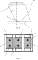
- Figure 1 shows an example of a mini-LED device 10.
- the product's first (top) surface side 2 contains pads that need to be aligned with the substrate pad 11 when placed.
- the second (bottom) surface side 3 of the product 10 is 'obscured' with a piece of sapphire 1, which is different on the top surface side 2 and on the bottom surface side 3 due to its slanted nature. Alignment of the pads on the top surface side 2 by measuring the bottom surface 3 side is therefore not possible.
- Figure 1 shows a schematic view of a sapphire 1 aligned with a substrate pad 11 (or the placing area 4). It may be seen that a top surface side 2 is not directly over the substrate pad 11. The alignment situation in which the top surface side 2 is directly over the substrate pad 11 is shown in Figure 2 , but in this case a bottom surface side 3 is not aligned with the substrate pad 11 on the placing area 4 thus resulting in an incorrect assembly.
- any other type of semiconductor component 10 can be used, preferably a silicon semiconductor component. Both examples can be used for visible and near infrared light sources
- the electronic component 10 can be placed on an integrated circuit substrate 11.
- a transfer substrate 11 can be used in particular in LED applications.
- the disclosure presents a method to provide a correct assembly while position an electronic component 10 while assembling is performed while only a top, first surface side 2 of the electronic component is visible.
- a method is performed on an electronic component 10 having a first, top surface side 2 and a second, bottom surface side 3 opposite to the first surface side 2.
- the electronic component 10 is illuminated, by means of a light source unit, with light which transmits through the electronic component 10, such that at least one feature of the electronic component 10 visible from the first surface side 2 and at least one feature 5 visible from the second surface side 3.
- step b an image of the electronic component 10 is obtained with a first camera unit.
- the image contains image data of the at least one feature present 5 visible from the first surface side 2 and at least one feature 5 visible from the second surface side 3.
- a correction value is calculated. This calculations are based on the image data from the image taken in the second step.
- the correction value is indicative of a position of the second surface side 3 of the electronic component 1 with respect to the first surface side 2 of the electronic component 10.
- the correction value is an offset, which informs how misaligned a first, top side 2 of the electronic component 10 has to be so that the second, bottom side 3 is placed in a designated place 4.
- step d the electronic component 10 is transferred to an assembling station. It should be noted that it is possible to perform all steps in one station which is able to take pictures, calculate and assembly. In such case the fourth step take place before a final assembly.
- step e a position of an adjusted placing area 4 of the electronic component 10 is calculated. It is done by adjusting a placing area 4, which is an area within the assembling station where the second side 3 of the electronic component 10 must by placed, with the correction value. This step may also be performed step d.
- step f the electronic component 10 is placed in the designated place 4.
- a second camera unit is used to keep track of the first, top surface side 2.
- the position information obtained from the image is directly correlated with the top side of the product.
- Alignment is performed based on internal structures 5 of a semiconductor product, instead of external (surface) structures. This is particularly useful for mini-LED and micro-LED product alignment, because of the extreme rough surface edges and the significant slanted sidewall edges which cannot be used for robust alignment.
- the light source unit emits light in the infrared or in the visible wavelength spectrum.
- Figure 3 shows three mini-LED products imaged through a sapphire top layer. Sapphire has a high transmission for visible light, so illuminating and imaging the product in visible light, in this case blue light with a wavelength of 457 nm, produced the highest contrast between the pads of the device and the rest of the image.
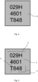
- Figure 4 shows a product image captured from the backside with visible light. Notice that no structures other than the rough outside edge of the product containing a serial number of the electronic component are visible here.
- Figure 5 shows the same product as in Figure 4 , now captured using near-infrared illumination. The internal features 5 become detectable and can be used for product alignment.
- the electronic component 10 is positioned between the light source unit and the first camera unit.
- the first camera unit is capturing light which passed through the electronic component 10.
- the light source unit and the first camera unit are pointing towards the same direction.
- the first camera unit is receiving a light which has been reflected from features of at least one feature 5 visible from the second surface side 3.
- a vision system is used consisting of a camera, optics and an illumination unit with a specific wavelength for which the obscuring part of the semiconductor product is highly transmissive, while at the same time reflective on the internal (metal) structures. This will make the internal structures visible in the captured image and available for alignment on a substrate.
- the position can be found via template matching, in which a reference image of the expected feature is defined as template and matched on every runtime captured image.
- the internal structures which are used as features to align on are typically low contrast and are only partly visible.
- a more advanced alignment technique based on a neural network can be used which is less sensitive for low contrast and occlusion of varying parts defined in a template reference.
- an axis of the first camera unit and/or the second camera unit is perpendicular to the first surface side 2 and/or the second surface side 3 of the electronic component 10.
- a plane of the first surface side 2 is perpendicular to the axis of the first camera unit and thus results in fewer image processing operation needed.
- this method may be used to place the electronic component 10 on an integrated circuit substrate.
- the electronic component 10 may be a sapphire component 1.
- the electronic component 10 may also be any other type of semiconductor component, preferably a silicon semiconductor component.
- a transfer substrate 11 can be used in particular in LED applications. Both examples can be used for visible and near infrared light sources.
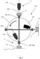
- the system 100 comprising a light source unit 101, a first camera unit 102, a second camera unit 103, a transportation unit 104, and a processing system (not shown).
- the first camera unit 102 is configured to obtain an image of the second surface side 3 of the electronic component 10 in a first measuring position X.
- the second camera unit 103 is configured to obtain an image of the first surface side 2 of the electronic component 10 in a second measuring position Y.
- the transportation unit 104 is configured to transport the electronic component 10 from the first measuring position X to the second measuring position Y.
- the processing system is configured to calculate, based on the image data, of a correction value wherein the correction value is indicative a position of the second surface side 3 of the electronic component 10 with respect to the first surface side 2 of the electronic component 10, and to calculate of position of an adjusted placing area of the electronic component 10 by adjusting a placing area 4, which is an area within the second measuring position Y where the second surface side 3 of the electronic component 10 must by placed on the designated place 4, with the correction value.
- the measuring of the first measuring position (for performing steps a, b) and the second measuring position (for performing step f) may take place in one space (for example in one device) which space (device) is configured to perform all tasks in one place.
- system 100 may also comprise a measuring unit 106 configured to hold the electronic component 10 in the first measuring position X.
- system 100 also comprises a holding unit 107 configured to hold the electronic component 10 in the second measuring position Y.
- the system 100 comprises an assembly device 108 configured to place the electronic component 10 on the placing area 4.
- the assembly device 108 may be, for example, a robotic arm 108a.
- the light source unit 102 emits an infrared light or a visible light.
- a type of the light depends on properties of a particular electronic device 10 to be placed.
- the measuring unit 106 is configured to hold the electronic component 10 between the light source unit 102 and the first camera unit 103.
- the first camera unit 102 is capturing light which passed through the electronic component 10.
- the light source unit 102 and the first camera unit 103 are pointing towards the same direction.
- the first camera unit 102 is receiving a light which has been reflected from features of at least one feature 5 visible from the second surface side 3.
- an axis 102z of the first camera unit 102 and/or an axis 103z of the second camera unit 103 is perpendicular to the first surface side 2 and/or the second surface side 3 of the electronic component 10.
- the measuring of the second measuring position can be performed either before or after the placement of the electronic component 10 on the substrate in the placing area 4, According, the second measuring position can be determined either while the electronic component 10 is still held by the transportation unit 104 or when the electronic component 10 is already placed on the substrate. At stated previously. both situations may depend on the alignment requirements of the specific application.
- the electronics side 2 of the electronic product 10 can be inspected prior to the placement on the substrate, whilst the electronic component is being held by the transportation unit 104. Accordingly, with the second measuring position Y and the correction value thus obtained prior to placement, proper alignment of the electronic product 10 with its second surface side 3 on the substrate on the placing area 4 can be achieved.
- the placement of the electronic product 10 on the substrate in the placing area 4 may need validation after the placement. Accordingly, a correction value is associated with the (non-aligning) features on the top side 2 in order to determine the actual placement position of the electronics on the other side of the electronic product relative to the substrate 11.
Landscapes
- Engineering & Computer Science (AREA)
- General Physics & Mathematics (AREA)
- Physics & Mathematics (AREA)
- Computer Hardware Design (AREA)
- Microelectronics & Electronic Packaging (AREA)
- Power Engineering (AREA)
- Manufacturing & Machinery (AREA)
- Condensed Matter Physics & Semiconductors (AREA)
- Theoretical Computer Science (AREA)
- Computer Vision & Pattern Recognition (AREA)
- Quality & Reliability (AREA)
- Container, Conveyance, Adherence, Positioning, Of Wafer (AREA)
- Supply And Installment Of Electrical Components (AREA)
- Length Measuring Devices By Optical Means (AREA)
- Led Devices (AREA)
- Wire Bonding (AREA)
- Die Bonding (AREA)
- Led Device Packages (AREA)
Claims (15)
- Verfahren zum Ausrichten und Platzieren eines elektronischen Bauteils, wobei das elektronische Bauteil (10) eine erste, obere Oberflächenseite (2) und eine zweite, untere Oberflächenseite (3) gegenüber der ersten Oberflächenseite (2) hat, wobei das Verfahren die folgenden Schritte umfassta. Beleuchten, unter Verwendung einer Lichtquelleneinheit, des elektronischen Bauteils (10) mit Licht, das durch das elektronische Bauteil (10) hindurchtritt, so dass mindestens ein Merkmal des elektronischen Bauteils (10) von der ersten Oberflächenseite und mindestens ein Merkmal (5) von der zweiten Oberflächenseite aus sichtbar ist,b. Erhalten, unter Verwendung einer ersten Kameraeinheit, eines Bildes des elektronischen Bauteils (10), das Bilddaten des mindestens einen von der ersten Oberflächenseite (2) sichtbaren Merkmals und des mindestens einen von der zweiten Oberflächenseite sichtbaren Merkmals (5) enthält;c. Berechnen eines Korrekturwertes auf der Grundlage der Bilddaten, wobei der Korrekturwert eine Position der zweiten Oberflächenseite (3) des elektronischen Bauteils (10) in Bezug auf die erste Oberflächenseite (2) des elektronischen Bauteils (10) angibt,d. Übergabe des elektronischen Bauteils an eine Montagestation;e. Berechnen einer Position eines eingestellten Platzierungsbereichs (4) des elektronischen Bauteils (10) durch Einstellen eines Platzierungsbereichs (4), der ein Bereich innerhalb der Montagestation ist, in dem die zweite Seite (3) des elektronischen Bauteils (10) platziert werden muss, mit dem Korrekturwert;f. Platzieren des elektronischen Bauteils (10) unter Verwendung einer zweiten Kameraeinheit durch Erhalten eines Bildes, das Bilddaten der ersten Oberflächenseite (2) des elektronischen Bauteils (10) enthält, und einer Montagevorrichtung, die so strukturiert ist, dass sie das elektronische Bauteil (10) platziert, so dass sich die erste Oberflächenseite (2) des elektronischen Bauteils (10) innerhalb des eingestellten Bestimmungsbereichs befindet.
- Verfahren nach Anspruch 1, wobei die Lichtquelleneinheit Licht im Infrarotbereich oder im sichtbaren Wellenlängenspektrum emittiert.
- Verfahren nach Anspruch 1 oder 2, wobei in den Schritten a. und b. das elektronische Bauteil (10) zwischen der Lichtquelleneinheit und der ersten Kameraeinheit positioniert wird.
- Verfahren nach Anspruch 1 oder 2, wobei in Schritt a. und b. die Lichtquelleneinheit und die erste Kameraeinheit in dieselbe Richtung zeigen.
- Verfahren nach einem oder mehreren der Ansprüche 1 bis 4, wobei in Schritt c. ein Template-Matching-Algorithmus oder ein oder mehrere maschinelle Lernalgorithmen verwendet werden.
- Verfahren nach einem oder mehreren der Ansprüche 1-5, wobei eine Achse der ersten Kameraeinheit und/oder der zweiten Kameraeinheit senkrecht zu der ersten Oberflächenseite (2) und/oder der zweiten Oberflächenseite (3) des elektronischen Bauteils (10) steht.
- Verfahren nach einem der Ansprüche 1-6, wobei das elektronische Bauteil (10) auf einem integrierten Schaltungssubstrat angeordnet ist.
- Verfahren nach einem der Ansprüche 1-7, wobei das elektronische Bauelement (10) ein Saphir-Bauelement oder eine andere Art von Halbleiter-Bauelement, vorzugsweise ein Silizium-Halbleiter-Bauelement, ist.
- System zum Ausrichten und Platzieren eines elektronischen Bauteils, umfassend:eine Lichtquelleneinheit,eine erste Kameraeinheit, die konfiguriert ist, um ein Bild eines elektronischen Bauteils (10) in einer ersten Messposition zu erhalten, wobei das elektronische Bauteil (10) eine erste, obere Oberflächenseite (2) und eine zweite, untere Oberflächenseite (3) gegenüber der ersten Oberflächenseite hat, wobei das Bild Bilddaten des mindestens einen von der ersten Oberflächenseite sichtbaren Merkmals und des mindestens einen von der zweiten Oberflächenseite sichtbaren Merkmals (5) enthält;eine zweite Kameraeinheit, die konfiguriert ist, um ein Bild der ersten Oberflächenseite (2) des elektronischen Bauteils (10) in einer zweiten Messposition zu erhalten,eine Transporteinheit, die konfiguriert ist, um das elektronische Bauteil (10) von der ersten Messposition zu der zweiten Messposition zu transportieren;ein Verarbeitungssystem, das konfiguriert ist, um auf der Grundlage der Bilddaten einen Korrekturwert zu berechnen, wobei der Korrekturwert eine Position der zweiten Oberflächenseite (3) des elektronischen Bauteils (10) in Bezug auf die erste Oberflächenseite (2) des elektronischen Bauteils (10) angibt, und die Position eines angepassten Platzierungsbereichs des elektronischen Bauteils (10) zu berechnen, indem es einen Platzierungsbereich (4), der ein Bereich innerhalb der zweiten Messposition ist, in dem die zweite Seite (3) des elektronischen Bauteils platziert werden muss, mit dem Korrekturwert anpasst.
- System nach Anspruch 9, ferner umfassend eine Messeinheit, die konfiguriert ist, um das elektronische Bauteil (10) in der ersten Messposition zu halten.
- System nach Anspruch 9 oder 10, ferner umfassend eine Halteeinheit, die konfiguriert ist, um das elektronische Bauteil (10) in der zweiten Messposition zu halten.
- System nach einem oder mehreren der Ansprüche 9 bis 11, ferner umfassend eine Montagevorrichtung, die konfiguriert ist, um das elektronische Bauteil (10) auf dem Platzierungsbereich (4) abzulegen.
- System nach einem oder mehreren der Ansprüche 9-12, wobei die Messeinheit konfiguriert ist, um das elektronische Bauteil (10) zwischen der Lichtquelleneinheit und der ersten Kameraeinheit zu halten.
- System nach einem oder mehreren der Ansprüche 9-13, wobei die Lichtquelleneinheit und die erste Kameraeinheit in dieselbe Richtung zeigen.
- System nach einem oder mehreren der Ansprüche 9-14, wobei eine Achse der ersten Kameraeinheit und/oder der zweiten Kameraeinheit senkrecht zu der ersten Oberflächenseite (2) und/oder der zweiten Oberflächenseite (3) des elektronischen Bauteils (10) steht.
Priority Applications (6)
| Application Number | Priority Date | Filing Date | Title |
|---|---|---|---|
| EP22151055.5A EP4210090B1 (de) | 2022-01-11 | 2022-01-11 | Verfahren zum ausrichten und platzieren eines elektronischen bauteils und system zum ausrichten und platzieren eines elektronischen bauteils |
| TW112100812A TW202405760A (zh) | 2022-01-11 | 2023-01-09 | 對準和放置電子部件的方法和對準和放置電子部件的系統 |
| KR1020230002715A KR20230108711A (ko) | 2022-01-11 | 2023-01-09 | 전자 구성요소를 정렬하고 배치하는 방법 및 전자 구성요소를 정렬하고 배치하기 위한 시스템 |
| CN202310037480.8A CN116435240A (zh) | 2022-01-11 | 2023-01-09 | 对准和放置电子部件的方法和对准和放置电子部件的系统 |
| JP2023001592A JP2023102279A (ja) | 2022-01-11 | 2023-01-10 | 電子部品の整列配置方法及び電子部品の整列配置システム |
| US18/152,834 US12482680B2 (en) | 2022-01-11 | 2023-01-11 | Method of aligning and placing an electronic component and a system for aligning and placing an electronic component |
Applications Claiming Priority (1)
| Application Number | Priority Date | Filing Date | Title |
|---|---|---|---|
| EP22151055.5A EP4210090B1 (de) | 2022-01-11 | 2022-01-11 | Verfahren zum ausrichten und platzieren eines elektronischen bauteils und system zum ausrichten und platzieren eines elektronischen bauteils |
Publications (2)
| Publication Number | Publication Date |
|---|---|
| EP4210090A1 EP4210090A1 (de) | 2023-07-12 |
| EP4210090B1 true EP4210090B1 (de) | 2024-10-30 |
Family
ID=79317187
Family Applications (1)
| Application Number | Title | Priority Date | Filing Date |
|---|---|---|---|
| EP22151055.5A Active EP4210090B1 (de) | 2022-01-11 | 2022-01-11 | Verfahren zum ausrichten und platzieren eines elektronischen bauteils und system zum ausrichten und platzieren eines elektronischen bauteils |
Country Status (6)
| Country | Link |
|---|---|
| US (1) | US12482680B2 (de) |
| EP (1) | EP4210090B1 (de) |
| JP (1) | JP2023102279A (de) |
| KR (1) | KR20230108711A (de) |
| CN (1) | CN116435240A (de) |
| TW (1) | TW202405760A (de) |
Family Cites Families (12)
| Publication number | Priority date | Publication date | Assignee | Title |
|---|---|---|---|---|
| US6389688B1 (en) * | 1997-06-18 | 2002-05-21 | Micro Robotics Systems, Inc. | Method and apparatus for chip placement |
| US6185816B1 (en) | 1999-07-06 | 2001-02-13 | Lucent Technologies Inc. | Alignment method |
| US8318512B2 (en) * | 2009-04-29 | 2012-11-27 | Applied Materials, Inc. | Automated substrate handling and film quality inspection in solar cell processing |
| US8750597B2 (en) | 2011-11-23 | 2014-06-10 | International Business Machines Corporation | Robust inspection alignment of semiconductor inspection tools using design information |
| DE102014101901B4 (de) * | 2014-02-14 | 2015-10-15 | Asm Assembly Systems Gmbh & Co. Kg | Optisches Vermessen eines Bauelementes mit an gegenüberliegenden Seiten vorhandenen strukturellen Merkmalen |
| US10153204B2 (en) * | 2014-06-04 | 2018-12-11 | Flir Systems, Inc. | Wafer level packaging of reduced-height infrared detectors |
| EP3734650B1 (de) * | 2016-08-29 | 2023-09-27 | EV Group E. Thallner GmbH | Verfahren und vorrichtung zum ausrichten von substraten |
| JP7097691B2 (ja) * | 2017-12-06 | 2022-07-08 | 東京エレクトロン株式会社 | ティーチング方法 |
| US12148181B2 (en) * | 2020-08-28 | 2024-11-19 | Canon Kabushiki Kaisha | Measurement apparatus that measures position information of measurement target in predetermined direction |
| KR102822419B1 (ko) * | 2020-12-08 | 2025-06-18 | 에스케이하이닉스 주식회사 | 반도체 제조 장치, 이를 이용하는 캐리어 위치 판독 방법 및 반도체 다이의 부착 방법 |
| KR102807827B1 (ko) * | 2021-08-27 | 2025-05-15 | 삼성전자주식회사 | 티칭 장치 및 이를 이용한 기판 정렬 장치 |
| KR20240115807A (ko) * | 2021-12-17 | 2024-07-26 | 에베 그룹 에. 탈너 게엠베하 | 감지 수단을 조정하는 장치 및 방법 |
-
2022
- 2022-01-11 EP EP22151055.5A patent/EP4210090B1/de active Active
-
2023
- 2023-01-09 KR KR1020230002715A patent/KR20230108711A/ko active Pending
- 2023-01-09 CN CN202310037480.8A patent/CN116435240A/zh active Pending
- 2023-01-09 TW TW112100812A patent/TW202405760A/zh unknown
- 2023-01-10 JP JP2023001592A patent/JP2023102279A/ja active Pending
- 2023-01-11 US US18/152,834 patent/US12482680B2/en active Active
Also Published As
| Publication number | Publication date |
|---|---|
| US12482680B2 (en) | 2025-11-25 |
| EP4210090A1 (de) | 2023-07-12 |
| CN116435240A (zh) | 2023-07-14 |
| JP2023102279A (ja) | 2023-07-24 |
| KR20230108711A (ko) | 2023-07-18 |
| TW202405760A (zh) | 2024-02-01 |
| US20230223286A1 (en) | 2023-07-13 |
Similar Documents
| Publication | Publication Date | Title |
|---|---|---|
| CN112534555B (zh) | 用于半导体加工的无线基片类示教传感器 | |
| US8582121B2 (en) | Article recognition apparatus and article processing apparatus using the same | |
| US6064756A (en) | Apparatus for three dimensional inspection of electronic components | |
| KR101200666B1 (ko) | 얼라이먼트 장치 제어 장치 및 얼라이먼트 방법 | |
| US20110234788A1 (en) | Assembly inspection apparatus and assembly processing apparatus using the same | |
| US20090009755A1 (en) | Method for detecting position of defect on semiconductor wafer | |
| EP3711908B1 (de) | Kalibrierungsvorrichtung für roboterarm | |
| JP2016173371A (ja) | 基板検査方法 | |
| US20020037098A1 (en) | Method and apparatus for three dimensional inspection of electronic components | |
| US20020034324A1 (en) | Method and apparatus for three dimensional inspection of electronic components | |
| US12224196B2 (en) | Semiconductor manufacturing apparatus, method of reading position of carrier, and method of attaching semiconductor die on carrier using semiconductor manufacturing apparatus | |
| US6952262B2 (en) | Exposure apparatus and aligning method | |
| CN111725086B (zh) | 半导体制造装置以及半导体器件的制造方法 | |
| EP4210090B1 (de) | Verfahren zum ausrichten und platzieren eines elektronischen bauteils und system zum ausrichten und platzieren eines elektronischen bauteils | |
| CN102549712B (zh) | 用于在键合之前检查芯片的方法和设备 | |
| US11031367B2 (en) | Bond head assemblies including reflective optical elements, related bonding machines, and related methods | |
| JP5975668B2 (ja) | ワーク搬送装置、ワーク搬送方法および組付部品の製造方法 | |
| TWI400020B (zh) | 整合電路板資訊之置件方法 | |
| JP2018155842A (ja) | 計測方法、計測プログラム、及び計測システム | |
| EP1218688A2 (de) | Verfahren und apparat für die dreidimensionale inspektion von elektronischen komponenten | |
| CN111473783B (zh) | 生产线编码处理系统与方法 | |
| KR20240104872A (ko) | 기판 처리 방법 및 기판 처리 시스템 | |
| JP2017183735A (ja) | 位置合わせ誤差を求めるための装置と方法 | |
| CN118553641A (zh) | 半导体制造装置、边缘的检测方法及半导体器件的制造方法 | |
| JP2001004696A (ja) | リード検出機能付きハンドリング装置及びそのリード検出方法 |
Legal Events
| Date | Code | Title | Description |
|---|---|---|---|
| PUAI | Public reference made under article 153(3) epc to a published international application that has entered the european phase |
Free format text: ORIGINAL CODE: 0009012 |
|
| STAA | Information on the status of an ep patent application or granted ep patent |
Free format text: STATUS: THE APPLICATION HAS BEEN PUBLISHED |
|
| AK | Designated contracting states |
Kind code of ref document: A1 Designated state(s): AL AT BE BG CH CY CZ DE DK EE ES FI FR GB GR HR HU IE IS IT LI LT LU LV MC MK MT NL NO PL PT RO RS SE SI SK SM TR |
|
| STAA | Information on the status of an ep patent application or granted ep patent |
Free format text: STATUS: REQUEST FOR EXAMINATION WAS MADE |
|
| 17P | Request for examination filed |
Effective date: 20231222 |
|
| RBV | Designated contracting states (corrected) |
Designated state(s): AL AT BE BG CH CY CZ DE DK EE ES FI FR GB GR HR HU IE IS IT LI LT LU LV MC MK MT NL NO PL PT RO RS SE SI SK SM TR |
|
| GRAP | Despatch of communication of intention to grant a patent |
Free format text: ORIGINAL CODE: EPIDOSNIGR1 |
|
| STAA | Information on the status of an ep patent application or granted ep patent |
Free format text: STATUS: GRANT OF PATENT IS INTENDED |
|
| RIC1 | Information provided on ipc code assigned before grant |
Ipc: H01L 21/67 20060101ALN20240503BHEP Ipc: H01L 21/68 20060101AFI20240503BHEP |
|
| INTG | Intention to grant announced |
Effective date: 20240524 |
|
| GRAS | Grant fee paid |
Free format text: ORIGINAL CODE: EPIDOSNIGR3 |
|
| GRAA | (expected) grant |
Free format text: ORIGINAL CODE: 0009210 |
|
| STAA | Information on the status of an ep patent application or granted ep patent |
Free format text: STATUS: THE PATENT HAS BEEN GRANTED |
|
| AK | Designated contracting states |
Kind code of ref document: B1 Designated state(s): AL AT BE BG CH CY CZ DE DK EE ES FI FR GB GR HR HU IE IS IT LI LT LU LV MC MK MT NL NO PL PT RO RS SE SI SK SM TR |
|
| REG | Reference to a national code |
Ref country code: GB Ref legal event code: FG4D |
|
| REG | Reference to a national code |
Ref country code: CH Ref legal event code: EP |
|
| REG | Reference to a national code |
Ref country code: DE Ref legal event code: R096 Ref document number: 602022007117 Country of ref document: DE |
|
| REG | Reference to a national code |
Ref country code: IE Ref legal event code: FG4D |
|
| REG | Reference to a national code |
Ref country code: LT Ref legal event code: MG9D |
|
| REG | Reference to a national code |
Ref country code: NL Ref legal event code: MP Effective date: 20241030 |
|
| PG25 | Lapsed in a contracting state [announced via postgrant information from national office to epo] |
Ref country code: HR Free format text: LAPSE BECAUSE OF FAILURE TO SUBMIT A TRANSLATION OF THE DESCRIPTION OR TO PAY THE FEE WITHIN THE PRESCRIBED TIME-LIMIT Effective date: 20241030 Ref country code: PT Free format text: LAPSE BECAUSE OF FAILURE TO SUBMIT A TRANSLATION OF THE DESCRIPTION OR TO PAY THE FEE WITHIN THE PRESCRIBED TIME-LIMIT Effective date: 20250228 Ref country code: IS Free format text: LAPSE BECAUSE OF FAILURE TO SUBMIT A TRANSLATION OF THE DESCRIPTION OR TO PAY THE FEE WITHIN THE PRESCRIBED TIME-LIMIT Effective date: 20250228 |
|
| PGFP | Annual fee paid to national office [announced via postgrant information from national office to epo] |
Ref country code: DE Payment date: 20250129 Year of fee payment: 4 |
|
| PG25 | Lapsed in a contracting state [announced via postgrant information from national office to epo] |
Ref country code: NL Free format text: LAPSE BECAUSE OF FAILURE TO SUBMIT A TRANSLATION OF THE DESCRIPTION OR TO PAY THE FEE WITHIN THE PRESCRIBED TIME-LIMIT Effective date: 20241030 Ref country code: FI Free format text: LAPSE BECAUSE OF FAILURE TO SUBMIT A TRANSLATION OF THE DESCRIPTION OR TO PAY THE FEE WITHIN THE PRESCRIBED TIME-LIMIT Effective date: 20241030 |
|
| REG | Reference to a national code |
Ref country code: AT Ref legal event code: MK05 Ref document number: 1737803 Country of ref document: AT Kind code of ref document: T Effective date: 20241030 |
|
| PG25 | Lapsed in a contracting state [announced via postgrant information from national office to epo] |
Ref country code: BG Free format text: LAPSE BECAUSE OF FAILURE TO SUBMIT A TRANSLATION OF THE DESCRIPTION OR TO PAY THE FEE WITHIN THE PRESCRIBED TIME-LIMIT Effective date: 20241030 |
|
| PG25 | Lapsed in a contracting state [announced via postgrant information from national office to epo] |
Ref country code: ES Free format text: LAPSE BECAUSE OF FAILURE TO SUBMIT A TRANSLATION OF THE DESCRIPTION OR TO PAY THE FEE WITHIN THE PRESCRIBED TIME-LIMIT Effective date: 20241030 |
|
| PG25 | Lapsed in a contracting state [announced via postgrant information from national office to epo] |
Ref country code: NO Free format text: LAPSE BECAUSE OF FAILURE TO SUBMIT A TRANSLATION OF THE DESCRIPTION OR TO PAY THE FEE WITHIN THE PRESCRIBED TIME-LIMIT Effective date: 20250130 |
|
| PG25 | Lapsed in a contracting state [announced via postgrant information from national office to epo] |
Ref country code: AT Free format text: LAPSE BECAUSE OF FAILURE TO SUBMIT A TRANSLATION OF THE DESCRIPTION OR TO PAY THE FEE WITHIN THE PRESCRIBED TIME-LIMIT Effective date: 20241030 Ref country code: GR Free format text: LAPSE BECAUSE OF FAILURE TO SUBMIT A TRANSLATION OF THE DESCRIPTION OR TO PAY THE FEE WITHIN THE PRESCRIBED TIME-LIMIT Effective date: 20250131 Ref country code: LV Free format text: LAPSE BECAUSE OF FAILURE TO SUBMIT A TRANSLATION OF THE DESCRIPTION OR TO PAY THE FEE WITHIN THE PRESCRIBED TIME-LIMIT Effective date: 20241030 |
|
| PG25 | Lapsed in a contracting state [announced via postgrant information from national office to epo] |
Ref country code: PL Free format text: LAPSE BECAUSE OF FAILURE TO SUBMIT A TRANSLATION OF THE DESCRIPTION OR TO PAY THE FEE WITHIN THE PRESCRIBED TIME-LIMIT Effective date: 20241030 |
|
| PG25 | Lapsed in a contracting state [announced via postgrant information from national office to epo] |
Ref country code: RS Free format text: LAPSE BECAUSE OF FAILURE TO SUBMIT A TRANSLATION OF THE DESCRIPTION OR TO PAY THE FEE WITHIN THE PRESCRIBED TIME-LIMIT Effective date: 20250130 |
|
| PG25 | Lapsed in a contracting state [announced via postgrant information from national office to epo] |
Ref country code: SM Free format text: LAPSE BECAUSE OF FAILURE TO SUBMIT A TRANSLATION OF THE DESCRIPTION OR TO PAY THE FEE WITHIN THE PRESCRIBED TIME-LIMIT Effective date: 20241030 |
|
| PG25 | Lapsed in a contracting state [announced via postgrant information from national office to epo] |
Ref country code: DK Free format text: LAPSE BECAUSE OF FAILURE TO SUBMIT A TRANSLATION OF THE DESCRIPTION OR TO PAY THE FEE WITHIN THE PRESCRIBED TIME-LIMIT Effective date: 20241030 |
|
| PG25 | Lapsed in a contracting state [announced via postgrant information from national office to epo] |
Ref country code: EE Free format text: LAPSE BECAUSE OF FAILURE TO SUBMIT A TRANSLATION OF THE DESCRIPTION OR TO PAY THE FEE WITHIN THE PRESCRIBED TIME-LIMIT Effective date: 20241030 |
|
| PG25 | Lapsed in a contracting state [announced via postgrant information from national office to epo] |
Ref country code: RO Free format text: LAPSE BECAUSE OF FAILURE TO SUBMIT A TRANSLATION OF THE DESCRIPTION OR TO PAY THE FEE WITHIN THE PRESCRIBED TIME-LIMIT Effective date: 20241030 |
|
| PG25 | Lapsed in a contracting state [announced via postgrant information from national office to epo] |
Ref country code: SK Free format text: LAPSE BECAUSE OF FAILURE TO SUBMIT A TRANSLATION OF THE DESCRIPTION OR TO PAY THE FEE WITHIN THE PRESCRIBED TIME-LIMIT Effective date: 20241030 |
|
| PG25 | Lapsed in a contracting state [announced via postgrant information from national office to epo] |
Ref country code: CZ Free format text: LAPSE BECAUSE OF FAILURE TO SUBMIT A TRANSLATION OF THE DESCRIPTION OR TO PAY THE FEE WITHIN THE PRESCRIBED TIME-LIMIT Effective date: 20241030 |
|
| PG25 | Lapsed in a contracting state [announced via postgrant information from national office to epo] |
Ref country code: IT Free format text: LAPSE BECAUSE OF FAILURE TO SUBMIT A TRANSLATION OF THE DESCRIPTION OR TO PAY THE FEE WITHIN THE PRESCRIBED TIME-LIMIT Effective date: 20241030 |
|
| REG | Reference to a national code |
Ref country code: DE Ref legal event code: R097 Ref document number: 602022007117 Country of ref document: DE |
|
| REG | Reference to a national code |
Ref country code: CH Ref legal event code: PL |
|
| PLBE | No opposition filed within time limit |
Free format text: ORIGINAL CODE: 0009261 |
|
| STAA | Information on the status of an ep patent application or granted ep patent |
Free format text: STATUS: NO OPPOSITION FILED WITHIN TIME LIMIT |
|
| PG25 | Lapsed in a contracting state [announced via postgrant information from national office to epo] |
Ref country code: SE Free format text: LAPSE BECAUSE OF FAILURE TO SUBMIT A TRANSLATION OF THE DESCRIPTION OR TO PAY THE FEE WITHIN THE PRESCRIBED TIME-LIMIT Effective date: 20241030 |
|
| PG25 | Lapsed in a contracting state [announced via postgrant information from national office to epo] |
Ref country code: LU Free format text: LAPSE BECAUSE OF NON-PAYMENT OF DUE FEES Effective date: 20250111 Ref country code: MC Free format text: LAPSE BECAUSE OF FAILURE TO SUBMIT A TRANSLATION OF THE DESCRIPTION OR TO PAY THE FEE WITHIN THE PRESCRIBED TIME-LIMIT Effective date: 20241030 |
|
| 26N | No opposition filed |
Effective date: 20250731 |
|
| PG25 | Lapsed in a contracting state [announced via postgrant information from national office to epo] |
Ref country code: BE Free format text: LAPSE BECAUSE OF NON-PAYMENT OF DUE FEES Effective date: 20250131 |
|
| PG25 | Lapsed in a contracting state [announced via postgrant information from national office to epo] |
Ref country code: FR Free format text: LAPSE BECAUSE OF NON-PAYMENT OF DUE FEES Effective date: 20250131 |
|
| PG25 | Lapsed in a contracting state [announced via postgrant information from national office to epo] |
Ref country code: CH Free format text: LAPSE BECAUSE OF NON-PAYMENT OF DUE FEES Effective date: 20250131 |
|
| REG | Reference to a national code |
Ref country code: BE Ref legal event code: MM Effective date: 20250131 |