EP4206151A1 - Handhabungseinheit zum bewegen eines formschliesselements einer maschine zur herstellung von glasartikeln - Google Patents
Handhabungseinheit zum bewegen eines formschliesselements einer maschine zur herstellung von glasartikeln Download PDFInfo
- Publication number
- EP4206151A1 EP4206151A1 EP22216908.8A EP22216908A EP4206151A1 EP 4206151 A1 EP4206151 A1 EP 4206151A1 EP 22216908 A EP22216908 A EP 22216908A EP 4206151 A1 EP4206151 A1 EP 4206151A1
- Authority
- EP
- European Patent Office
- Prior art keywords
- mold
- handling unit
- shaft
- machine
- closing
- Prior art date
- Legal status (The legal status is an assumption and is not a legal conclusion. Google has not performed a legal analysis and makes no representation as to the accuracy of the status listed.)
- Granted
Links
Images

Classifications
-
- C—CHEMISTRY; METALLURGY
- C03—GLASS; MINERAL OR SLAG WOOL
- C03B—MANUFACTURE, SHAPING, OR SUPPLEMENTARY PROCESSES
- C03B9/00—Blowing glass; Production of hollow glass articles
- C03B9/13—Blowing glass; Production of hollow glass articles in gob feeder machines
-
- C—CHEMISTRY; METALLURGY
- C03—GLASS; MINERAL OR SLAG WOOL
- C03B—MANUFACTURE, SHAPING, OR SUPPLEMENTARY PROCESSES
- C03B11/00—Pressing molten glass or performed glass reheated to equivalent low viscosity without blowing
- C03B11/16—Gearing or controlling mechanisms specially adapted for glass presses
-
- C—CHEMISTRY; METALLURGY
- C03—GLASS; MINERAL OR SLAG WOOL
- C03B—MANUFACTURE, SHAPING, OR SUPPLEMENTARY PROCESSES
- C03B9/00—Blowing glass; Production of hollow glass articles
- C03B9/13—Blowing glass; Production of hollow glass articles in gob feeder machines
- C03B9/193—Blowing glass; Production of hollow glass articles in gob feeder machines in "press-and-blow" machines
- C03B9/1932—Details of such machines, e.g. plungers or plunger mechanisms for the press-and-blow machine, cooling of plungers
-
- C—CHEMISTRY; METALLURGY
- C03—GLASS; MINERAL OR SLAG WOOL
- C03B—MANUFACTURE, SHAPING, OR SUPPLEMENTARY PROCESSES
- C03B11/00—Pressing molten glass or performed glass reheated to equivalent low viscosity without blowing
- C03B11/14—Pressing laminated glass articles or glass with metal inserts or enclosures, e.g. wires, bubbles, coloured parts
-
- C—CHEMISTRY; METALLURGY
- C03—GLASS; MINERAL OR SLAG WOOL
- C03B—MANUFACTURE, SHAPING, OR SUPPLEMENTARY PROCESSES
- C03B9/00—Blowing glass; Production of hollow glass articles
-
- C—CHEMISTRY; METALLURGY
- C03—GLASS; MINERAL OR SLAG WOOL
- C03B—MANUFACTURE, SHAPING, OR SUPPLEMENTARY PROCESSES
- C03B9/00—Blowing glass; Production of hollow glass articles
- C03B9/13—Blowing glass; Production of hollow glass articles in gob feeder machines
- C03B9/14—Blowing glass; Production of hollow glass articles in gob feeder machines in "blow" machines or in "blow-and-blow" machines
- C03B9/16—Blowing glass; Production of hollow glass articles in gob feeder machines in "blow" machines or in "blow-and-blow" machines in machines with turn-over moulds
- C03B9/165—Details of such machines, e.g. guide funnels, turn-over mechanisms
Definitions
- the present invention relates to a handling unit for moving a mold closing element of a forming machine for producing hollow glass articles.
- forming machines universally known as IS machines, are used to form hollow glass articles.
- Such machines comprise a plurality of forming sections arranged side by side, into each of which a succession of drops of glass enters and from each of which a succession of formed hollow glass articles exits.
- Each molding section comprises a blank mold and a finishing mold arranged downstream of the blank mold. Both molds can have a single forming cavity or a plurality of forming cavities arranged next to one another.
- each forming cavity is open in an upward direction and must be closed fluid-tight at the top during the forming phase of the glass article.
- Each cavity is accordingly provided with a related closing element which extends vertically and closes the related cavity completely in the case of blank molds, or partially in the case of finishing molds, thus allowing a flow of compressed forming air to be introduced into the finishing molds from above.
- the closing elements of a same mold are carried by a dedicated supporting head, which is connected to a free end of an arm.
- the arm extends in a cantilever manner from a motorized vertical drive shaft, and is coupled to said shaft by means of a respective attachment clamp fixed to the column by means of clamping screws.
- the vertical shaft and, together with the latter, the related arm are vertically movable in order to move the related closing elements between a raised resting position and a lowered operating position, in which the related closing elements are coupled to the respective mold in a fluid-tight manner.
- IS machines are set up to be provided with different molds depending on the article to be produced. These molds have different dimensions and, in particular, different heights.
- the height position of the closing elements must be adjusted according to the height of the mold that will be mounted on the machine and so that the closing elements are always coupled tightly to the mold when arranged in their lowered operating position.
- Adjustment is currently carried out manually by a team of responsible operators, who, at each mold change, demount the closing elements and mount the respective setting templates, known in the jargon as “callipers” or “face mold", in their stead.
- Each face mold is dimensioned so as to couple with the mold on the machine in exactly the same way as the related closing element and has a height that is less than the height of the related closing element so as to take into account the inevitable deformations of the handling unit under working conditions.
- the clamping screws of the clamp are loosened under the control of one of the responsible operators and the arm and the related head lowered or raised until the face molds are coupled to and in abutment with the related mold underneath.
- the clamp is, still manually, tightened again on the vertical shaft, effectively rendering the arm integral with said vertical shaft, after which the face molds are demounted and, in their stead, the closing elements dedicated to the new mold are mounted on the machine.
- the foregoing operations require, for each mold in the section, at least a pair of responsible operators. This is because at least one of the operators has to support the arm-head assembly while the other operator loosens the clamping screws of the clamp and both accompany the arm and related head during the vertical repositioning.
- the loosening of the screws, the accompanying of the head and the correct positioning and coupling of the face molds to the related mold are operations that require experience and considerable coordination between the operators inasmuch as they must be conducted so as to avoid a jamming of the clamp on the shaft due to the fact that the arm and the head protrude in a cantilever manner from the vertical shaft.
- the aim of the present invention is to provide a handling unit for moving a mold closing element of a forming machine that allows the problems set out above to be solved in a simple and cost-effective manner.
- a particular aim of the present invention is to provide a handling unit that allows an adjustment of the closing elements to be carried out quickly, extremely safely and precisely while eliminating operator discretion.
- a further aim of the present invention is to provide a handling unit that allows drastically reducing or at least simplifying manual operations, reducing or eliminating the physical effort required of operators, as well as reducing the number of operators responsible for such adjustments so as to minimize operating costs and machine downtime.
- a last aim of the present invention is to provide a handling unit which is simple and cost-effective to produce, compact and which can be inspected and operated from the outside.
- a handling unit for moving at least one mold closing element in a machine for forming glass articles is provided, as defined in the appended claims.
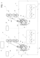
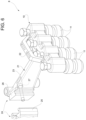
- a forming machine for forming glass articles is indicated, as a whole, by 1.
- the machine 1 comprises a plurality of forming sections 2, only one of which is visible in the attached figures.
- Each forming section 2 comprises a blank mold 3 comprising, in this specific case, four forming cavities 4 arranged side by side and open in an upward direction and a finishing mold 5 also comprising four finishing cavities 6 open in an upward direction.
- the molds 3 and 4 comprise a different number of cavities 4,6.
- the machine 1 further comprises a closing assembly 8 for closing the cavities 4 of the blank mold 3 and a closing assembly 9 for closing the cavities 6 of the finishing mold 5 and configured to allow compressed air to be introduced into said cavities 6.
- the assembly 8 comprises a supporting head 10 and, for each cavity 4, a closing element 11, known per se and not described in detail.
- Each closing element 11 is coupled to the head 10 in a manner known per se, protrudes vertically downwards and is configured to couple with the mold 3 in order to completely close the related cavity 4.
- Each assembly 8 further includes a handling unit 13 for moving the head 10 and the related closing elements 11.
- the unit 13 comprises a dedicated attachment frame 14 fixed to a structure 15 of the machine 1 in proximity of the blank mold 3 ( Figure 1 ).
- the unit 13 further comprises a related drive shaft 16, which has a vertical axis 18, a straight upper end section 19 projecting upwards beyond the frame 14 and a lower end section (not visible in the attached figures) coupled to a drive device K, known per se and not described in detail, for moving the shaft 16 with a roto-translatory motion along the axis 18.
- a related drive shaft 16 which has a vertical axis 18, a straight upper end section 19 projecting upwards beyond the frame 14 and a lower end section (not visible in the attached figures) coupled to a drive device K, known per se and not described in detail, for moving the shaft 16 with a roto-translatory motion along the axis 18.
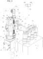
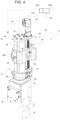
- the unit 13 finally comprises a slide 20 coupled to the section 19 so as to be slidable along the axis 18 in opposite directions, and an arm 21 that supports the head 10 and extends orthogonally to the axis 18.
- the slide 20 can be locked manually from the outside by means of a dedicated wrench acting, for example, on a screw 20A.
- the slide 20 is locked on the section 19 by means of a motorized locking device, e.g., of a mechanical friction or magnetic type and in any event a device that can be controlled from outside the machine or remotely.
- a motorized locking device e.g., of a mechanical friction or magnetic type and in any event a device that can be controlled from outside the machine or remotely.
- the arm 21 comprises a free end portion 22 firmly connected to the head 10 and an attachment end portion 23, opposite the portion 22 and coupled to the slide 20 by means of a releasable coupling 24 for the quick replacement of the arm-supporting head assembly.
- the coupling 24 comprises a vertical guide 25 parallel to the axis 18 and firmly connected to the slide 20, and a slide 26 firmly connected to the attachment portion 23 and couplable from above to the guide 25.
- the slide 26 is clamped on the guide 25 in a releasable manner by means of a clamping screw 27, which can be actuated manually from the outside by means of a dedicated wrench.
- the slide 26 is locked on the guide 25 by means of a motorized locking device, e.g., of a mechanical friction or magnetic type and in any event a device that can be controlled from outside the machine or remotely.
- the slide 20 is movable along the section 19 under the thrust of a mechanical transmission 30, which in the described example is of a screw type.
- the mechanical transmission 30 is a toothed transmission or some other equivalent linear transmission.
- the transmission 30 comprises a screw 31 arranged outside the section 19 of the vertical shaft 16 and coupled to the vertical shaft 16 in a rotatable manner about its axis 31A and in an axially fixed position, and a nut screw 32 engaged by the screw 31 and coupled to the slide 20 in a vertically and angularly fixed position with respect to said slide 20.
- the screw 31 is rotated by an electric motor 35.
- the transmission 30 comprises an attachment bracket 36, in turn comprising an anchoring portion 37 arranged resting on an upper end of the shaft 16 and an attachment portion 38 protruding in a cantilevered manner from the anchoring portion 37.
- the screw 30 is coupled to the attachment portion 38 in a rotatable manner and in an axially fixed position, protrudes upwards beyond said attachment portion 38 and is firmly connected to the rotor of the motor 35.
- the motor 35 extends upwards from the attachment portion 38, to which it is firmly attached.
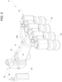
- the electric motor 35 is commanded and controlled by a command and control unit 40.
- the unit 40 comprises a memory block 40A storing, for each mold 3,5 that is installable on the machine 1, a respective reference position of the closing elements 11, i.e. their correct height position, and a command and control block 40B for controlling the motor 35 and moving the closing elements 11 into the reference or operating positions depending on the mold currently mounted on the machine 1.
- each unit 40 communicates with a general machine unit 41 that synchronizes the position adjustment activities of all relevant closing elements 11 by controlling all of said closing assemblies in response to a mold change program.
- each assembly 9 is similar to the assembly 8 described in the foregoing, from which it differs only by comprising, instead of the head 10, a head 43 that supports closing elements 45.
- the closing elements 45 also known per se, differ from the elements 11 in that they couple to each cavity 6 fluid-tightly and respectively define a respective compressed air supply duct within the related cavities 6.
- the head 43 further differs from the head 10 in that it carries ducts 45A for supplying compressed air to the respective closing elements 45.
- the screw 31 is rotated about its own axis 31A by acting manually from the outside on a motion input shaft 46, which is part of a worm screw - worm gear transmission 47, fixed to the portion 19 of the shaft 16 by means of a collar 48 ( Figure 2 ).
- the shaft 46 extends orthogonally to the axis 31A outside the arm 21 and slide 20, and the transmission 47 forms part of the transmission 30.
- the precision and continuity with which the arms 21, and with them the related heads 10,43, are moved allow a single operator to carry out the height adjustment at a mold change without the need to demount and remount the closing elements 11,45 from the related heads 10,43 and, above all, compared to known solutions, to be able to adjust the height of the closing elements 11 and 45 without having to use "face molds", which can consequently be completely eliminated, thus fundamentally solving all the problems linked with the handling and storage of the same.
- the arms 21 only move with a translatory motion, i.e. they translate while remaining parallel to themselves, so that the spatial orientation of the closing elements 11,45 is not altered.
- the presence of the drive motors 35 and the presence of the related command and control units eliminate the arbitrariness of the movement as there is a transition from little more than a visual control on the part of the operator to a fully automatic control of the individual section 2 or of the entire machine 1 on the basis of information stored in memories or databases, for example in said command and control unit.
- the provided handling units 13 are simple in design, cost-effective and, above all, extremely compact as well as being immediately inspectable from the outside.
- the arms 21 and heads 10,43 can have different shapes and geometries from those indicated, for example in order to support a different number of closing elements.
- the transmissions 30 could be provided with both motors 35 and transmissions 47 so as to be capable of manual operation in any operating condition including failures of the electrical control.
Landscapes
- Engineering & Computer Science (AREA)
- Chemical & Material Sciences (AREA)
- Manufacturing & Machinery (AREA)
- Materials Engineering (AREA)
- Organic Chemistry (AREA)
- Moulds For Moulding Plastics Or The Like (AREA)
- Glass Compositions (AREA)
- Re-Forming, After-Treatment, Cutting And Transporting Of Glass Products (AREA)
- Manipulator (AREA)
Applications Claiming Priority (1)
| Application Number | Priority Date | Filing Date | Title |
|---|---|---|---|
| IT102021000032888A IT202100032888A1 (it) | 2021-12-29 | 2021-12-29 | Gruppo di movimentazione di un organo di chiusura di uno stampo di una macchina per la formatura di articoli di vetro |
Publications (2)
| Publication Number | Publication Date |
|---|---|
| EP4206151A1 true EP4206151A1 (de) | 2023-07-05 |
| EP4206151B1 EP4206151B1 (de) | 2026-02-11 |
Family
ID=80685177
Family Applications (1)
| Application Number | Title | Priority Date | Filing Date |
|---|---|---|---|
| EP22216908.8A Active EP4206151B1 (de) | 2021-12-29 | 2022-12-28 | Handhabungseinheit zum bewegen eines formschliesselements einer maschine zur herstellung von glasartikeln |
Country Status (5)
| Country | Link |
|---|---|
| US (1) | US20230202900A1 (de) |
| EP (1) | EP4206151B1 (de) |
| JP (1) | JP2023098860A (de) |
| CN (1) | CN116354587A (de) |
| IT (1) | IT202100032888A1 (de) |
Citations (3)
| Publication number | Priority date | Publication date | Assignee | Title |
|---|---|---|---|---|
| US3383193A (en) * | 1964-10-26 | 1968-05-14 | Maul Bros Inc | Glass-molding apparatus |
| US4695307A (en) * | 1985-07-24 | 1987-09-22 | Emhart Industries, Inc. | Baffle moving mechanism for use in a glassware manufacturing machine of the individual section type |
| US20120111424A1 (en) * | 2010-11-04 | 2012-05-10 | Heye International Gmbh | Module for Transferring a Component Between Two Positions |
-
2021
- 2021-12-29 IT IT102021000032888A patent/IT202100032888A1/it unknown
-
2022
- 2022-12-22 US US18/145,619 patent/US20230202900A1/en active Pending
- 2022-12-27 JP JP2022210454A patent/JP2023098860A/ja active Pending
- 2022-12-27 CN CN202211682475.4A patent/CN116354587A/zh active Pending
- 2022-12-28 EP EP22216908.8A patent/EP4206151B1/de active Active
Patent Citations (3)
| Publication number | Priority date | Publication date | Assignee | Title |
|---|---|---|---|---|
| US3383193A (en) * | 1964-10-26 | 1968-05-14 | Maul Bros Inc | Glass-molding apparatus |
| US4695307A (en) * | 1985-07-24 | 1987-09-22 | Emhart Industries, Inc. | Baffle moving mechanism for use in a glassware manufacturing machine of the individual section type |
| US20120111424A1 (en) * | 2010-11-04 | 2012-05-10 | Heye International Gmbh | Module for Transferring a Component Between Two Positions |
Also Published As
| Publication number | Publication date |
|---|---|
| JP2023098860A (ja) | 2023-07-11 |
| CN116354587A (zh) | 2023-06-30 |
| EP4206151B1 (de) | 2026-02-11 |
| US20230202900A1 (en) | 2023-06-29 |
| IT202100032888A1 (it) | 2023-06-29 |
Similar Documents
| Publication | Publication Date | Title |
|---|---|---|
| US4431896A (en) | Method and apparatus for orienting the wire guidance heads on spark erosion cutting equipment for eroding with a great wire slope | |
| GB2178421A (en) | Electronic glass feeder plunger operating mechanism | |
| US5282732A (en) | Mold press assembly | |
| EP4206151A1 (de) | Handhabungseinheit zum bewegen eines formschliesselements einer maschine zur herstellung von glasartikeln | |
| EP2722314B1 (de) | Maschine zur herstellung von hohlem glas und dazu gehörendem verfahren | |
| JPH0241369B2 (de) | ||
| JPH11199242A (ja) | I.s.機械用の金型開閉機構 | |
| JP2010207893A (ja) | プレス機 | |
| US20230166449A1 (en) | 3d printer | |
| CN109967891A (zh) | 一种高精度的汽车配件截断装置 | |
| CN103347673A (zh) | 立式注射成型机的加热筒更换方法及加热筒更换夹具 | |
| JPS624429Y2 (de) | ||
| CN224128472U (zh) | 一种自动调整激光安全防护机构的装置 | |
| CN220028212U (zh) | 一种棒材轧制导向模具 | |
| CN217346577U (zh) | 一种注塑机的机械保护装置 | |
| JPH11199241A (ja) | I.s.機械用のプランジャ機構及びプランジャ基部モジュール並びにi.s.機械 | |
| JPH05261461A (ja) | コイルばね成形機械 | |
| CN223000407U (zh) | 一种模具加工检测用定位装置 | |
| EP3867202B1 (de) | Kolbenanordnung zur formung von bändern aus geschmolzenem glas | |
| CN222095468U (zh) | 一种机床上下料定位机构 | |
| CN114247778A (zh) | 折弯机六轴后挡料结构 | |
| JPH11199240A (ja) | I.s.機械 | |
| CN118003120B (zh) | 高精度航空叶片立式加工中心 | |
| CN223353519U (zh) | 一种钻孔攻丝切割一体化自动加工设备 | |
| CN221087913U (zh) | 一种模具抽芯套快速拆装机构 |
Legal Events
| Date | Code | Title | Description |
|---|---|---|---|
| PUAI | Public reference made under article 153(3) epc to a published international application that has entered the european phase |
Free format text: ORIGINAL CODE: 0009012 |
|
| STAA | Information on the status of an ep patent application or granted ep patent |
Free format text: STATUS: THE APPLICATION HAS BEEN PUBLISHED |
|
| AK | Designated contracting states |
Kind code of ref document: A1 Designated state(s): AL AT BE BG CH CY CZ DE DK EE ES FI FR GB GR HR HU IE IS IT LI LT LU LV MC ME MK MT NL NO PL PT RO RS SE SI SK SM TR |
|
| STAA | Information on the status of an ep patent application or granted ep patent |
Free format text: STATUS: REQUEST FOR EXAMINATION WAS MADE |
|
| 17P | Request for examination filed |
Effective date: 20240103 |
|
| RBV | Designated contracting states (corrected) |
Designated state(s): AL AT BE BG CH CY CZ DE DK EE ES FI FR GB GR HR HU IE IS IT LI LT LU LV MC ME MK MT NL NO PL PT RO RS SE SI SK SM TR |
|
| GRAP | Despatch of communication of intention to grant a patent |
Free format text: ORIGINAL CODE: EPIDOSNIGR1 |
|
| STAA | Information on the status of an ep patent application or granted ep patent |
Free format text: STATUS: GRANT OF PATENT IS INTENDED |
|
| INTG | Intention to grant announced |
Effective date: 20250911 |
|
| GRAS | Grant fee paid |
Free format text: ORIGINAL CODE: EPIDOSNIGR3 |
|
| GRAA | (expected) grant |
Free format text: ORIGINAL CODE: 0009210 |
|
| STAA | Information on the status of an ep patent application or granted ep patent |
Free format text: STATUS: THE PATENT HAS BEEN GRANTED |
|
| P01 | Opt-out of the competence of the unified patent court (upc) registered |
Free format text: CASE NUMBER: UPC_APP_0015684_4206151/2025 Effective date: 20251203 |
|
| AK | Designated contracting states |
Kind code of ref document: B1 Designated state(s): AL AT BE BG CH CY CZ DE DK EE ES FI FR GB GR HR HU IE IS IT LI LT LU LV MC ME MK MT NL NO PL PT RO RS SE SI SK SM TR |
|
| REG | Reference to a national code |
Ref country code: CH Ref legal event code: F10 Free format text: ST27 STATUS EVENT CODE: U-0-0-F10-F00 (AS PROVIDED BY THE NATIONAL OFFICE) Effective date: 20260211 Ref country code: GB Ref legal event code: FG4D Ref country code: CH Ref legal event code: R17 Free format text: ST27 STATUS EVENT CODE: U-0-0-R10-R17 (AS PROVIDED BY THE NATIONAL OFFICE) Effective date: 20260211 |
|
| REG | Reference to a national code |
Ref country code: DE Ref legal event code: R096 Ref document number: 602022030126 Country of ref document: DE |
|
| REG | Reference to a national code |
Ref country code: IE Ref legal event code: FG4D |