EP4204239B1 - Dispositif d'étanchéité pour moyeu de roue motrice et bol de transmission a cannelures - Google Patents
Dispositif d'étanchéité pour moyeu de roue motrice et bol de transmission a cannelures Download PDFInfo
- Publication number
- EP4204239B1 EP4204239B1 EP22700843.0A EP22700843A EP4204239B1 EP 4204239 B1 EP4204239 B1 EP 4204239B1 EP 22700843 A EP22700843 A EP 22700843A EP 4204239 B1 EP4204239 B1 EP 4204239B1
- Authority
- EP
- European Patent Office
- Prior art keywords
- sealing device
- wheel hub
- transmission
- static
- static sealing
- Prior art date
- Legal status (The legal status is an assumption and is not a legal conclusion. Google has not performed a legal analysis and makes no representation as to the accuracy of the status listed.)
- Active
Links
Images


Classifications
-
- B—PERFORMING OPERATIONS; TRANSPORTING
- B60—VEHICLES IN GENERAL
- B60B—VEHICLE WHEELS; CASTORS; AXLES FOR WHEELS OR CASTORS; INCREASING WHEEL ADHESION
- B60B27/00—Hubs
- B60B27/0073—Hubs characterised by sealing means
-
- B—PERFORMING OPERATIONS; TRANSPORTING
- B60—VEHICLES IN GENERAL
- B60B—VEHICLE WHEELS; CASTORS; AXLES FOR WHEELS OR CASTORS; INCREASING WHEEL ADHESION
- B60B27/00—Hubs
- B60B27/0005—Hubs with ball bearings
-
- B—PERFORMING OPERATIONS; TRANSPORTING
- B60—VEHICLES IN GENERAL
- B60B—VEHICLE WHEELS; CASTORS; AXLES FOR WHEELS OR CASTORS; INCREASING WHEEL ADHESION
- B60B27/00—Hubs
- B60B27/0015—Hubs for driven wheels
-
- B—PERFORMING OPERATIONS; TRANSPORTING
- B60—VEHICLES IN GENERAL
- B60B—VEHICLE WHEELS; CASTORS; AXLES FOR WHEELS OR CASTORS; INCREASING WHEEL ADHESION
- B60B27/00—Hubs
- B60B27/0015—Hubs for driven wheels
- B60B27/0036—Hubs for driven wheels comprising homokinetic joints
Definitions
- the invention relates, in general, to the technical field of motor vehicles and more particularly to that of drive wheel hub assemblies.
- a wheel hub In drive wheel hub assemblies, a wheel hub is guided in rotation by a rolling bearing mechanically attached to a wheel support. In order to transmit the rotational movement coming from the transmission of the motor vehicle to the drive wheels, the hub is connected in rotation to a transmission bowl by a set of splines.
- Such an assembly presents an axial play requiring the addition of a device for sealing this axial play in order to protect the set of splines.
- the rotational connection of the drive wheel hub and the transmission bowl is generally done by a set of axial or radial splines formed on the parts of the wheel hub and the transmission bowl cooperating with each other.
- the wheel hub is mechanically connected to a wheel support by a roller bearing whose rear bearing faces the transmission bowl.
- the assembly of the splines of the transmission bowl and the wheel hub forms one or more gaps between the parts of the wheel hub and the transmission bowl facing each other due to the contact which is established between the splines. It is also possible that continuous contact can form around the entire perimeter of the splines following tightening. For convenience of language, it is this contact zone with or without gap which will be called "axial play" in the following, although there is strictly no talk about no play in the assembly of the transmission bowl and the wheel hub. In fact, this axial play exposes the splines to dirt which can damage them.
- This configuration leads to the fitting of numerous parts in a reduced area and requires a static seal of complex shape and comprising flexible parts assembled most often by overmolding to metal frames of complex shapes.
- the invention aims, according to a first aspect, at a static sealing device capable of covering an axial clearance formed between a rear hub end of a wheel hub and a front face of a transmission bowl of a transmission bowl.
- THE static sealing device comprises an axial sealing element capable of cooperating with a rear face of an inner ring of an inner ring of a rolling bearing of the wheel hub, and a radial sealing element capable of cooperating with a bulb extension of a transmission bowl.
- said static sealing device cooperates with a cap ring formed at the rear end of the hub to contribute to the sealing at the front part of said static sealing device.
- the sealing device comprises a second radial sealing element formed by a front part of said static sealing device resting on the cap ring.
- the static sealing device comprises a sealing sleeve, the axial sealing element is formed by a front end of the sealing sleeve, and/or the first radial sealing element is produced by at least one part of an inner casing of the sealing sleeve pressing on the bulb extension of the transmission bowl.
- an armature is integrated into a part of the sealing sleeve distinct from the radial sealing element and capable of being mounted tight on the bulb extension of the transmission bowl.
- the sealing sleeve is made of polymer material such as thermoplastic materials of the PA6 or PA12 type or elastomeric materials of the rubber type, NBR, HNBR, ACM or FKM.
- the static sealing device is fitted onto the crown of the bolt.
- the sealing element has a flange on the side of the inner ring and a front face of the flange rests on the rear face of the inner ring, and/or the radial sealing element is formed by a radial sealing lip resting on the bulb extension of the transmission bowl.
- the flange of the seal is fitted onto the seal, a tongue located at the level of the flange is housed between the rear face of the inner ring and a crown of the seal, and/or the radial sealing lip has a converging profile oriented towards the transmission bowl.
- said static sealing device (11) is made of thermoplastic material such as TPE, TPP, TPC, TPA, TPV, polyurethane, or polyurethane foams.
- a baffle device is arranged around the periphery of the static sealing device of the first or second embodiment, and it is capable of cooperating with a complementary element mechanically connected to a wheel support and located near the device. static sealing; and or
- an encoder is located on a portion of the static sealing device.
- the coder is made by ferromagnetic particles dispersed in the material constituting the sealing device, or a polymer matrix overmolded or fixed on the sealing device.
- a drive wheel hub assembly comprises a rolling bearing comprising at least one inner ring mechanically connected to a rotating part of a wheel hub, and a transmission bowl mechanically connected at least in rotation at the rotating part of a wheel hub so as to form an axial clearance between a rear end of the hub and a front face of the transmission bowl.
- the drive wheel hub assembly further includes a static seal covering axial clearance, and as described above.
- a motor vehicle comprises at least one drive wheel hub assembly as described above.
- the inner ring 5 of the rear ball bearing 2b is mounted on the rotating part 6a of the wheel hub 6 and stopped axially towards the rear thereon by a bolt 20 cold formed at a rear end of hub 9.
- the stud 20 comes to press against a rear face 13 of the inner ring 5 to immobilize it.
- the front and rear ball bearings 2a and 2b are angular contact ball bearings; it goes without saying that other rolling bodies can be used such as conical rollers.
- the outer and inner rings of the front bearing can be attached instead of being formed directly in the rotating and static parts of the wheel hub.
- the clearance 8 is formed between the front end of the bulb extension 7b and the rear face of the button 20a which respectively belong to the transmission bowl 7 and to the rotating part of the wheel hub 6a, connected together by the splines .
- the clearance 8 can be covered by a static sealing device in order to protect the splines.
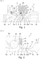
- the sealing device covering the clearance 8 is a static seal 11 described below and illustrated in [ Fig.2 ].
- the static seal 11 To assemble the static seal 11, it is first fitted onto the bolt 20 of the rotating part of the wheel hub 6a. During shrinking, the front face of the collar 18 rests on the rear face of the inner ring 13. Optionally, the tongue 21 is inserted between the rear face of the inner ring 13 and the front part of the ring crown 20b. Alternatively or in addition to the shrink fit, the wedging of the tongue 21 between the inner ring 5 and the button 20 ensures mechanical retention by clipping the static seal 11 onto the rotating part of the wheel hub 6a. The improvement in the maintenance of the static seal 11 on the ring crown 20b ensures better cohesion of the static seal 1 washed the wheel hub 6 during the assembly phases and the resulting manipulations.
- the seal 11 can be pre-installed on the wheel hub assembly 1 and therefore be delivered with it by the supplier bearing waiting to be assembled with the transmission bowl 7.
- Fig.3 shows an alternative configuration of the static seal 11.
- the seal instead of extending from the rear face of the inner ring 13 to the bulb 7a of the transmission bowl 7, stops to the radial sealing lip 14.
- the outer casing of the bulb extension 15 has a suitable diameter to guarantee suitable interference with a view to generating good pressure of the radial sealing lip 14 on the outer casing of the bulb extension 15.
- the radial sealing lip 14 also optionally has the chamfer 19.
- a baffle device 22 is located on the periphery of the sealing device 23, here the seal 11.
- the baffle device 22 is formed of two baffle rings 22a installed on an outer envelope of the sealing device 23. These two baffle rings 22a cooperate with an annular extension 24 of the wheel support 4 located around the seal 11.
- This baffle device 22 makes it possible to improve the dynamic sealing of the rear bearing in addition, for example, of a cassette seal 28.
- the baffle device 22 complements the other sealing elements in order to form a first barrier against dirt projected into this sensitive area of the wheel hub assembly 1.
- the wings 22a are sufficiently flexible so that during assembly they can deform in order to pass on either side of the annular extension 24 and to allow their unmolding.
- the baffle device 22 can be provided on a second embodiment of the sealing device as shown in figures 5 and 6 and described below.
- the seal 11 is made of a material allowing a large radial elastic deformation while allowing sufficient pressure to be exerted at the level of the axial and radial sealing zones, for example a flexible thermoplastic material such as TPE, TPP, TPC, TPA, TPV, polyurethane, or polyurethane foams.
- a flexible thermoplastic material such as TPE, TPP, TPC, TPA, TPV, polyurethane, or polyurethane foams.
- FIG.5 shows a detail view of the wheel hub assembly 1 at the axial clearance 8 and the inner ring 5 of the rear ball bearing 2b.
- the static sealing device of the [ Fig.5 ] has a sealing sleeve 16 of generally cylindrical shape, extending substantially from the rear face 13 of the inner ring 5 to the foot of the bulb 7a of the transmission bowl 7.
- a front end 16a of the sealing sleeve 16 is plated against the rear face of the inner ring 13 in order to produce the axial seal protecting the axial clearance 8 on the side of the inner ring 5.
- the rear part of the sealing sleeve 16 is fitted onto the bulb extension 7b of the bowl of transmission.
- an inner envelope of the sealing sleeve 16b is pressed against the outer envelope of the extension of the bulb 15 which provides the radial seal protecting the axial play 8 on the side of the transmission bowl 7.
- a variant of this configuration consists of fixing mechanically, for example by overmolding, the sealing sleeve 16 on a frame 17, for example made of metal, which is mounted tight on the extension of the bulb 7b.
- the reinforcement 17 ensures the mechanical strength of the sealing sleeve 16 on the transmission bowl 7, while the radial sealing is ensured by the pressure of a part of the inner envelope of the sealing sleeve 16b on the outer casing of the bulb extension 15.
- the inner surface of the sealing sleeve 16 Before mounting the armature on the bulb extension 7b, the inner surface of the sealing sleeve 16 has a diameter greater than that of the part of the inner envelope of the sealing sleeve 16b which presses on the outer envelope of the bulb extension 15 to ensure radial sealing.
Landscapes
- Engineering & Computer Science (AREA)
- Mechanical Engineering (AREA)
- Sealing With Elastic Sealing Lips (AREA)
- Sealing Using Fluids, Sealing Without Contact, And Removal Of Oil (AREA)
- Sealing Of Bearings (AREA)
- Rolling Contact Bearings (AREA)
Applications Claiming Priority (2)
| Application Number | Priority Date | Filing Date | Title |
|---|---|---|---|
| FR2100633A FR3119113B1 (fr) | 2021-01-22 | 2021-01-22 | Dispositif d’étanchéité pour moyeu de roue motrice et bol de transmission à cannelures |
| PCT/EP2022/051301 WO2022157283A1 (fr) | 2021-01-22 | 2022-01-21 | Dispositif d'étanchéité pour moyeu de roue motrice et bol de transmission a cannelures |
Publications (2)
| Publication Number | Publication Date |
|---|---|
| EP4204239A1 EP4204239A1 (fr) | 2023-07-05 |
| EP4204239B1 true EP4204239B1 (fr) | 2024-07-10 |
Family
ID=74759143
Family Applications (1)
| Application Number | Title | Priority Date | Filing Date |
|---|---|---|---|
| EP22700843.0A Active EP4204239B1 (fr) | 2021-01-22 | 2022-01-21 | Dispositif d'étanchéité pour moyeu de roue motrice et bol de transmission a cannelures |
Country Status (5)
| Country | Link |
|---|---|
| EP (1) | EP4204239B1 (https=) |
| JP (1) | JP2024504356A (https=) |
| CN (1) | CN116867651A (https=) |
| FR (1) | FR3119113B1 (https=) |
| WO (1) | WO2022157283A1 (https=) |
Families Citing this family (3)
| Publication number | Priority date | Publication date | Assignee | Title |
|---|---|---|---|---|
| DE102023202581B4 (de) * | 2023-03-22 | 2025-03-13 | Volkswagen Aktiengesellschaft | Axial verspannte Plankerbverzahnungsanordnung und Verfahren zum Fügen eines Gleichlaufgelenks mit einer Radnabe mit Radlager unter Verwendung einer Plankerbverzahnungsanordnung |
| TWI859809B (zh) * | 2023-04-10 | 2024-10-21 | 天心工業股份有限公司 | 磁阻式自行車頭碗 |
| DE102024209038A1 (de) | 2024-09-20 | 2026-03-26 | Volkswagen Aktiengesellschaft | Axial verspannte Plankerbverzahnungsanordnung mit Schnappdichtring |
Family Cites Families (10)
| Publication number | Priority date | Publication date | Assignee | Title |
|---|---|---|---|---|
| JP4439331B2 (ja) * | 2004-05-17 | 2010-03-24 | Ntn株式会社 | 車輪用軸受装置 |
| US8210752B2 (en) * | 2007-09-26 | 2012-07-03 | Jtekt Corporation | Wheel supporting device |
| JP5061818B2 (ja) * | 2007-09-26 | 2012-10-31 | 株式会社ジェイテクト | 車輪支持装置 |
| JP2009248672A (ja) * | 2008-04-03 | 2009-10-29 | Ntn Corp | 車輪用軸受装置 |
| CN102056752B (zh) * | 2008-06-04 | 2013-11-13 | Ntn株式会社 | 驱动轮用轴承装置 |
| JP5683776B2 (ja) * | 2008-08-14 | 2015-03-11 | Ntn株式会社 | 駆動車輪用軸受装置 |
| DE102008050127A1 (de) | 2008-10-06 | 2010-04-08 | Schaeffler Kg | Vorrichtung zur axialen Fixierung |
| FR3001509B1 (fr) * | 2013-01-28 | 2015-06-26 | Ntn Snr Roulements | Palier a roulement notamment pour systeme d’entrainement en rotation d’une roue de vehicule automobile |
| DE102014210732A1 (de) * | 2014-06-05 | 2015-12-17 | Schaeffler Technologies AG & Co. KG | Lageranordnung, umfassend einem optimierten Dichtring mit Dichtelement |
| KR101857193B1 (ko) * | 2016-08-17 | 2018-06-25 | 주식회사 일진글로벌 | 구동 휠 베어링 |
-
2021
- 2021-01-22 FR FR2100633A patent/FR3119113B1/fr active Active
-
2022
- 2022-01-21 EP EP22700843.0A patent/EP4204239B1/fr active Active
- 2022-01-21 WO PCT/EP2022/051301 patent/WO2022157283A1/fr not_active Ceased
- 2022-01-21 JP JP2023544199A patent/JP2024504356A/ja active Pending
- 2022-01-21 CN CN202280011159.6A patent/CN116867651A/zh active Pending
Also Published As
| Publication number | Publication date |
|---|---|
| JP2024504356A (ja) | 2024-01-31 |
| EP4204239A1 (fr) | 2023-07-05 |
| CN116867651A (zh) | 2023-10-10 |
| WO2022157283A1 (fr) | 2022-07-28 |
| FR3119113B1 (fr) | 2024-11-29 |
| FR3119113A1 (fr) | 2022-07-29 |
Similar Documents
| Publication | Publication Date | Title |
|---|---|---|
| EP4204239B1 (fr) | Dispositif d'étanchéité pour moyeu de roue motrice et bol de transmission a cannelures | |
| EP1425192B1 (fr) | Dispositif de butee de suspension | |
| FR2678692A1 (fr) | Ensemble capteur etanche integrable dans un roulement a capteur d'informations et roulement equipe d'un tel ensemble. | |
| EP1225360A1 (fr) | Dispositif auto-centreur de butée de débrayage | |
| FR2865008A1 (fr) | Dispositif de roulement de butee de suspension. | |
| FR3006711A1 (fr) | Systeme d'entrainement de pompe a eau et procede de montage | |
| FR2630179A1 (fr) | Joint d'etancheite en cartouche | |
| FR2527286A1 (fr) | Frein a disque a etrier flottant | |
| FR2827351A1 (fr) | Palier a corps roulants coniques pourvu d'un dispositif d'etancheite | |
| FR2504231A3 (fr) | Joint d'etancheite comprenant deux levres dont l'une est axiale et l'autre radiale, ainsi qu'un labyrinthe | |
| EP1210525A1 (fr) | Butee de debrayage a auto-alignement par manchon elastique | |
| EP4311957B1 (fr) | Joint d'étanchéite statique et ensemble de moyeu de roue motrice l'intégrant | |
| FR2499910A1 (fr) | Moyeu de roue entraine par un joint homocinetique | |
| EP1433968B1 (fr) | Palier à roulement freiné compact | |
| FR3090060A1 (fr) | Dispositif de poulie | |
| EP4204700B1 (fr) | Palier lisse ou à roulement equipé d'un dispositif d'étanchéité avec un siège de joint proche de l'axe de révolution | |
| FR2548595A1 (fr) | Ensemble de moyeu de roue motrice de vehicule | |
| FR2661470A1 (fr) | Roulement de butee, notamment a usage de butee de debrayage. | |
| FR3010753A1 (fr) | Dispositif de butee de debrayage, notamment pour embrayage de vehicule automobile | |
| WO2022161735A1 (fr) | Roulement de roue equipe d'un dispositif d'etancheite a gouttiere et chicane | |
| FR2714943A1 (fr) | Roulement équipé d'un dispositif d'étanchéité pour passage de fluide. | |
| FR2576985A1 (fr) | Palier a interposer radialement entre deux pieces rotative s, notamment aux embrayages pour vehicules automobiles et procede de montage d'un tel palier | |
| FR3041287A1 (fr) | Butee de suspension comportant une piste de roulement en metal et une coupelle en plastique | |
| FR2908728A1 (fr) | Dispositif de fixation de pivot de roue de vehicule automobile. | |
| EP0543727B1 (fr) | Tube-guide à étanchéité intégrée pour butée de débrayage de boîte de vitesses de véhicule automobile |
Legal Events
| Date | Code | Title | Description |
|---|---|---|---|
| STAA | Information on the status of an ep patent application or granted ep patent |
Free format text: STATUS: UNKNOWN |
|
| STAA | Information on the status of an ep patent application or granted ep patent |
Free format text: STATUS: THE INTERNATIONAL PUBLICATION HAS BEEN MADE |
|
| PUAI | Public reference made under article 153(3) epc to a published international application that has entered the european phase |
Free format text: ORIGINAL CODE: 0009012 |
|
| STAA | Information on the status of an ep patent application or granted ep patent |
Free format text: STATUS: REQUEST FOR EXAMINATION WAS MADE |
|
| 17P | Request for examination filed |
Effective date: 20230328 |
|
| AK | Designated contracting states |
Kind code of ref document: A1 Designated state(s): AL AT BE BG CH CY CZ DE DK EE ES FI FR GB GR HR HU IE IS IT LI LT LU LV MC MK MT NL NO PL PT RO RS SE SI SK SM TR |
|
| RAP3 | Party data changed (applicant data changed or rights of an application transferred) |
Owner name: NTN EUROPE |
|
| GRAP | Despatch of communication of intention to grant a patent |
Free format text: ORIGINAL CODE: EPIDOSNIGR1 |
|
| STAA | Information on the status of an ep patent application or granted ep patent |
Free format text: STATUS: GRANT OF PATENT IS INTENDED |
|
| DAV | Request for validation of the european patent (deleted) | ||
| DAX | Request for extension of the european patent (deleted) | ||
| INTG | Intention to grant announced |
Effective date: 20240304 |
|
| TPAC | Observations filed by third parties |
Free format text: ORIGINAL CODE: EPIDOSNTIPA |
|
| GRAS | Grant fee paid |
Free format text: ORIGINAL CODE: EPIDOSNIGR3 |
|
| GRAA | (expected) grant |
Free format text: ORIGINAL CODE: 0009210 |
|
| STAA | Information on the status of an ep patent application or granted ep patent |
Free format text: STATUS: THE PATENT HAS BEEN GRANTED |
|
| AK | Designated contracting states |
Kind code of ref document: B1 Designated state(s): AL AT BE BG CH CY CZ DE DK EE ES FI FR GB GR HR HU IE IS IT LI LT LU LV MC MK MT NL NO PL PT RO RS SE SI SK SM TR |
|
| REG | Reference to a national code |
Ref country code: CH Ref legal event code: EP |
|
| REG | Reference to a national code |
Ref country code: DE Ref legal event code: R096 Ref document number: 602022004485 Country of ref document: DE |
|
| P01 | Opt-out of the competence of the unified patent court (upc) registered |
Free format text: CASE NUMBER: APP_43590/2024 Effective date: 20240725 |
|
| REG | Reference to a national code |
Ref country code: LT Ref legal event code: MG9D |
|
| REG | Reference to a national code |
Ref country code: NL Ref legal event code: MP Effective date: 20240710 |
|
| PG25 | Lapsed in a contracting state [announced via postgrant information from national office to epo] |
Ref country code: PT Free format text: LAPSE BECAUSE OF FAILURE TO SUBMIT A TRANSLATION OF THE DESCRIPTION OR TO PAY THE FEE WITHIN THE PRESCRIBED TIME-LIMIT Effective date: 20241111 |
|
| REG | Reference to a national code |
Ref country code: AT Ref legal event code: MK05 Ref document number: 1701740 Country of ref document: AT Kind code of ref document: T Effective date: 20240710 |
|
| PG25 | Lapsed in a contracting state [announced via postgrant information from national office to epo] |
Ref country code: NL Free format text: LAPSE BECAUSE OF FAILURE TO SUBMIT A TRANSLATION OF THE DESCRIPTION OR TO PAY THE FEE WITHIN THE PRESCRIBED TIME-LIMIT Effective date: 20240710 |
|
| PG25 | Lapsed in a contracting state [announced via postgrant information from national office to epo] |
Ref country code: PT Free format text: LAPSE BECAUSE OF FAILURE TO SUBMIT A TRANSLATION OF THE DESCRIPTION OR TO PAY THE FEE WITHIN THE PRESCRIBED TIME-LIMIT Effective date: 20241111 Ref country code: NL Free format text: LAPSE BECAUSE OF FAILURE TO SUBMIT A TRANSLATION OF THE DESCRIPTION OR TO PAY THE FEE WITHIN THE PRESCRIBED TIME-LIMIT Effective date: 20240710 |
|
| PG25 | Lapsed in a contracting state [announced via postgrant information from national office to epo] |
Ref country code: NO Free format text: LAPSE BECAUSE OF FAILURE TO SUBMIT A TRANSLATION OF THE DESCRIPTION OR TO PAY THE FEE WITHIN THE PRESCRIBED TIME-LIMIT Effective date: 20241010 |
|
| PG25 | Lapsed in a contracting state [announced via postgrant information from national office to epo] |
Ref country code: GR Free format text: LAPSE BECAUSE OF FAILURE TO SUBMIT A TRANSLATION OF THE DESCRIPTION OR TO PAY THE FEE WITHIN THE PRESCRIBED TIME-LIMIT Effective date: 20241011 Ref country code: FI Free format text: LAPSE BECAUSE OF FAILURE TO SUBMIT A TRANSLATION OF THE DESCRIPTION OR TO PAY THE FEE WITHIN THE PRESCRIBED TIME-LIMIT Effective date: 20240710 Ref country code: PL Free format text: LAPSE BECAUSE OF FAILURE TO SUBMIT A TRANSLATION OF THE DESCRIPTION OR TO PAY THE FEE WITHIN THE PRESCRIBED TIME-LIMIT Effective date: 20240710 |
|
| PG25 | Lapsed in a contracting state [announced via postgrant information from national office to epo] |
Ref country code: BG Free format text: LAPSE BECAUSE OF FAILURE TO SUBMIT A TRANSLATION OF THE DESCRIPTION OR TO PAY THE FEE WITHIN THE PRESCRIBED TIME-LIMIT Effective date: 20240710 |
|
| PG25 | Lapsed in a contracting state [announced via postgrant information from national office to epo] |
Ref country code: LV Free format text: LAPSE BECAUSE OF FAILURE TO SUBMIT A TRANSLATION OF THE DESCRIPTION OR TO PAY THE FEE WITHIN THE PRESCRIBED TIME-LIMIT Effective date: 20240710 |
|
| PG25 | Lapsed in a contracting state [announced via postgrant information from national office to epo] |
Ref country code: IS Free format text: LAPSE BECAUSE OF FAILURE TO SUBMIT A TRANSLATION OF THE DESCRIPTION OR TO PAY THE FEE WITHIN THE PRESCRIBED TIME-LIMIT Effective date: 20241110 Ref country code: AT Free format text: LAPSE BECAUSE OF FAILURE TO SUBMIT A TRANSLATION OF THE DESCRIPTION OR TO PAY THE FEE WITHIN THE PRESCRIBED TIME-LIMIT Effective date: 20240710 |
|
| PG25 | Lapsed in a contracting state [announced via postgrant information from national office to epo] |
Ref country code: HR Free format text: LAPSE BECAUSE OF FAILURE TO SUBMIT A TRANSLATION OF THE DESCRIPTION OR TO PAY THE FEE WITHIN THE PRESCRIBED TIME-LIMIT Effective date: 20240710 |
|
| PG25 | Lapsed in a contracting state [announced via postgrant information from national office to epo] |
Ref country code: ES Free format text: LAPSE BECAUSE OF FAILURE TO SUBMIT A TRANSLATION OF THE DESCRIPTION OR TO PAY THE FEE WITHIN THE PRESCRIBED TIME-LIMIT Effective date: 20240710 Ref country code: RS Free format text: LAPSE BECAUSE OF FAILURE TO SUBMIT A TRANSLATION OF THE DESCRIPTION OR TO PAY THE FEE WITHIN THE PRESCRIBED TIME-LIMIT Effective date: 20241010 |
|
| PG25 | Lapsed in a contracting state [announced via postgrant information from national office to epo] |
Ref country code: RS Free format text: LAPSE BECAUSE OF FAILURE TO SUBMIT A TRANSLATION OF THE DESCRIPTION OR TO PAY THE FEE WITHIN THE PRESCRIBED TIME-LIMIT Effective date: 20241010 Ref country code: PL Free format text: LAPSE BECAUSE OF FAILURE TO SUBMIT A TRANSLATION OF THE DESCRIPTION OR TO PAY THE FEE WITHIN THE PRESCRIBED TIME-LIMIT Effective date: 20240710 Ref country code: NO Free format text: LAPSE BECAUSE OF FAILURE TO SUBMIT A TRANSLATION OF THE DESCRIPTION OR TO PAY THE FEE WITHIN THE PRESCRIBED TIME-LIMIT Effective date: 20241010 Ref country code: LV Free format text: LAPSE BECAUSE OF FAILURE TO SUBMIT A TRANSLATION OF THE DESCRIPTION OR TO PAY THE FEE WITHIN THE PRESCRIBED TIME-LIMIT Effective date: 20240710 Ref country code: IS Free format text: LAPSE BECAUSE OF FAILURE TO SUBMIT A TRANSLATION OF THE DESCRIPTION OR TO PAY THE FEE WITHIN THE PRESCRIBED TIME-LIMIT Effective date: 20241110 Ref country code: HR Free format text: LAPSE BECAUSE OF FAILURE TO SUBMIT A TRANSLATION OF THE DESCRIPTION OR TO PAY THE FEE WITHIN THE PRESCRIBED TIME-LIMIT Effective date: 20240710 Ref country code: GR Free format text: LAPSE BECAUSE OF FAILURE TO SUBMIT A TRANSLATION OF THE DESCRIPTION OR TO PAY THE FEE WITHIN THE PRESCRIBED TIME-LIMIT Effective date: 20241011 Ref country code: FI Free format text: LAPSE BECAUSE OF FAILURE TO SUBMIT A TRANSLATION OF THE DESCRIPTION OR TO PAY THE FEE WITHIN THE PRESCRIBED TIME-LIMIT Effective date: 20240710 Ref country code: ES Free format text: LAPSE BECAUSE OF FAILURE TO SUBMIT A TRANSLATION OF THE DESCRIPTION OR TO PAY THE FEE WITHIN THE PRESCRIBED TIME-LIMIT Effective date: 20240710 Ref country code: BG Free format text: LAPSE BECAUSE OF FAILURE TO SUBMIT A TRANSLATION OF THE DESCRIPTION OR TO PAY THE FEE WITHIN THE PRESCRIBED TIME-LIMIT Effective date: 20240710 Ref country code: AT Free format text: LAPSE BECAUSE OF FAILURE TO SUBMIT A TRANSLATION OF THE DESCRIPTION OR TO PAY THE FEE WITHIN THE PRESCRIBED TIME-LIMIT Effective date: 20240710 |
|
| REG | Reference to a national code |
Ref country code: DE Ref legal event code: R097 Ref document number: 602022004485 Country of ref document: DE |
|
| PG25 | Lapsed in a contracting state [announced via postgrant information from national office to epo] |
Ref country code: DK Free format text: LAPSE BECAUSE OF FAILURE TO SUBMIT A TRANSLATION OF THE DESCRIPTION OR TO PAY THE FEE WITHIN THE PRESCRIBED TIME-LIMIT Effective date: 20240710 Ref country code: RO Free format text: LAPSE BECAUSE OF FAILURE TO SUBMIT A TRANSLATION OF THE DESCRIPTION OR TO PAY THE FEE WITHIN THE PRESCRIBED TIME-LIMIT Effective date: 20240710 Ref country code: SM Free format text: LAPSE BECAUSE OF FAILURE TO SUBMIT A TRANSLATION OF THE DESCRIPTION OR TO PAY THE FEE WITHIN THE PRESCRIBED TIME-LIMIT Effective date: 20240710 |
|
| PG25 | Lapsed in a contracting state [announced via postgrant information from national office to epo] |
Ref country code: EE Free format text: LAPSE BECAUSE OF FAILURE TO SUBMIT A TRANSLATION OF THE DESCRIPTION OR TO PAY THE FEE WITHIN THE PRESCRIBED TIME-LIMIT Effective date: 20240710 |
|
| PG25 | Lapsed in a contracting state [announced via postgrant information from national office to epo] |
Ref country code: CZ Free format text: LAPSE BECAUSE OF FAILURE TO SUBMIT A TRANSLATION OF THE DESCRIPTION OR TO PAY THE FEE WITHIN THE PRESCRIBED TIME-LIMIT Effective date: 20240710 |
|
| PG25 | Lapsed in a contracting state [announced via postgrant information from national office to epo] |
Ref country code: SK Free format text: LAPSE BECAUSE OF FAILURE TO SUBMIT A TRANSLATION OF THE DESCRIPTION OR TO PAY THE FEE WITHIN THE PRESCRIBED TIME-LIMIT Effective date: 20240710 Ref country code: IT Free format text: LAPSE BECAUSE OF FAILURE TO SUBMIT A TRANSLATION OF THE DESCRIPTION OR TO PAY THE FEE WITHIN THE PRESCRIBED TIME-LIMIT Effective date: 20240710 |
|
| PLBE | No opposition filed within time limit |
Free format text: ORIGINAL CODE: 0009261 |
|
| STAA | Information on the status of an ep patent application or granted ep patent |
Free format text: STATUS: NO OPPOSITION FILED WITHIN TIME LIMIT |
|
| 26N | No opposition filed |
Effective date: 20250411 |
|
| REG | Reference to a national code |
Ref country code: CH Ref legal event code: PL |
|
| PG25 | Lapsed in a contracting state [announced via postgrant information from national office to epo] |
Ref country code: SE Free format text: LAPSE BECAUSE OF FAILURE TO SUBMIT A TRANSLATION OF THE DESCRIPTION OR TO PAY THE FEE WITHIN THE PRESCRIBED TIME-LIMIT Effective date: 20240710 |
|
| PG25 | Lapsed in a contracting state [announced via postgrant information from national office to epo] |
Ref country code: MC Free format text: LAPSE BECAUSE OF FAILURE TO SUBMIT A TRANSLATION OF THE DESCRIPTION OR TO PAY THE FEE WITHIN THE PRESCRIBED TIME-LIMIT Effective date: 20240710 Ref country code: LU Free format text: LAPSE BECAUSE OF NON-PAYMENT OF DUE FEES Effective date: 20250121 |
|
| PG25 | Lapsed in a contracting state [announced via postgrant information from national office to epo] |
Ref country code: BE Free format text: LAPSE BECAUSE OF NON-PAYMENT OF DUE FEES Effective date: 20250131 |
|
| PG25 | Lapsed in a contracting state [announced via postgrant information from national office to epo] |
Ref country code: CH Free format text: LAPSE BECAUSE OF NON-PAYMENT OF DUE FEES Effective date: 20250131 |
|
| REG | Reference to a national code |
Ref country code: BE Ref legal event code: MM Effective date: 20250131 |
|
| PG25 | Lapsed in a contracting state [announced via postgrant information from national office to epo] |
Ref country code: IE Free format text: LAPSE BECAUSE OF NON-PAYMENT OF DUE FEES Effective date: 20250121 |
|
| PGFP | Annual fee paid to national office [announced via postgrant information from national office to epo] |
Ref country code: DE Payment date: 20260121 Year of fee payment: 5 |
|
| PGFP | Annual fee paid to national office [announced via postgrant information from national office to epo] |
Ref country code: FR Payment date: 20260123 Year of fee payment: 5 |