EP4201748A1 - An einem mobilen körper montierte anzeigevorrichtung - Google Patents
An einem mobilen körper montierte anzeigevorrichtung Download PDFInfo
- Publication number
- EP4201748A1 EP4201748A1 EP21858414.2A EP21858414A EP4201748A1 EP 4201748 A1 EP4201748 A1 EP 4201748A1 EP 21858414 A EP21858414 A EP 21858414A EP 4201748 A1 EP4201748 A1 EP 4201748A1
- Authority
- EP
- European Patent Office
- Prior art keywords
- semi
- mobile
- transmissive layer
- outer cover
- display device
- Prior art date
- Legal status (The legal status is an assumption and is not a legal conclusion. Google has not performed a legal analysis and makes no representation as to the accuracy of the status listed.)
- Withdrawn
Links
- 239000003973 paint Substances 0.000 claims description 12
- 239000002184 metal Substances 0.000 claims description 4
- 239000002985 plastic film Substances 0.000 claims description 4
- 229920003023 plastic Polymers 0.000 claims description 3
- 239000000758 substrate Substances 0.000 description 14
- 238000001035 drying Methods 0.000 description 3
- 210000000078 claw Anatomy 0.000 description 2
- 239000000853 adhesive Substances 0.000 description 1
- 230000001070 adhesive effect Effects 0.000 description 1
- 239000000470 constituent Substances 0.000 description 1
- 230000000694 effects Effects 0.000 description 1
- 238000005401 electroluminescence Methods 0.000 description 1
- 238000001125 extrusion Methods 0.000 description 1
- 238000001746 injection moulding Methods 0.000 description 1
- WABPQHHGFIMREM-UHFFFAOYSA-N lead(0) Chemical compound [Pb] WABPQHHGFIMREM-UHFFFAOYSA-N 0.000 description 1
- 239000000463 material Substances 0.000 description 1
- 238000007747 plating Methods 0.000 description 1
- 229920003229 poly(methyl methacrylate) Polymers 0.000 description 1
- 239000004926 polymethyl methacrylate Substances 0.000 description 1
- 238000007789 sealing Methods 0.000 description 1
- 239000000243 solution Substances 0.000 description 1
- 238000004544 sputter deposition Methods 0.000 description 1
- 238000007740 vapor deposition Methods 0.000 description 1
Images


Classifications
-
- B—PERFORMING OPERATIONS; TRANSPORTING
- B60—VEHICLES IN GENERAL
- B60R—VEHICLES, VEHICLE FITTINGS, OR VEHICLE PARTS, NOT OTHERWISE PROVIDED FOR
- B60R11/00—Arrangements for holding or mounting articles, not otherwise provided for
- B60R11/02—Arrangements for holding or mounting articles, not otherwise provided for for radio sets, television sets, telephones, or the like; Arrangement of controls thereof
- B60R11/0229—Arrangements for holding or mounting articles, not otherwise provided for for radio sets, television sets, telephones, or the like; Arrangement of controls thereof for displays, e.g. cathodic tubes
- B60R11/0235—Arrangements for holding or mounting articles, not otherwise provided for for radio sets, television sets, telephones, or the like; Arrangement of controls thereof for displays, e.g. cathodic tubes of flat type, e.g. LCD
-
- B—PERFORMING OPERATIONS; TRANSPORTING
- B60—VEHICLES IN GENERAL
- B60Q—ARRANGEMENT OF SIGNALLING OR LIGHTING DEVICES, THE MOUNTING OR SUPPORTING THEREOF OR CIRCUITS THEREFOR, FOR VEHICLES IN GENERAL
- B60Q1/00—Arrangement of optical signalling or lighting devices, the mounting or supporting thereof or circuits therefor
- B60Q1/26—Arrangement of optical signalling or lighting devices, the mounting or supporting thereof or circuits therefor the devices being primarily intended to indicate the vehicle, or parts thereof, or to give signals, to other traffic
- B60Q1/50—Arrangement of optical signalling or lighting devices, the mounting or supporting thereof or circuits therefor the devices being primarily intended to indicate the vehicle, or parts thereof, or to give signals, to other traffic for indicating other intentions or conditions, e.g. request for waiting or overtaking
- B60Q1/503—Arrangement of optical signalling or lighting devices, the mounting or supporting thereof or circuits therefor the devices being primarily intended to indicate the vehicle, or parts thereof, or to give signals, to other traffic for indicating other intentions or conditions, e.g. request for waiting or overtaking using luminous text or symbol displays in or on the vehicle, e.g. static text
- B60Q1/5035—Arrangement of optical signalling or lighting devices, the mounting or supporting thereof or circuits therefor the devices being primarily intended to indicate the vehicle, or parts thereof, or to give signals, to other traffic for indicating other intentions or conditions, e.g. request for waiting or overtaking using luminous text or symbol displays in or on the vehicle, e.g. static text electronic displays
-
- B—PERFORMING OPERATIONS; TRANSPORTING
- B60—VEHICLES IN GENERAL
- B60R—VEHICLES, VEHICLE FITTINGS, OR VEHICLE PARTS, NOT OTHERWISE PROVIDED FOR
- B60R19/00—Wheel guards; Radiator guards, e.g. grilles; Obstruction removers; Fittings damping bouncing force in collisions
- B60R19/52—Radiator or grille guards ; Radiator grilles
-
- G—PHYSICS
- G09—EDUCATION; CRYPTOGRAPHY; DISPLAY; ADVERTISING; SEALS
- G09F—DISPLAYING; ADVERTISING; SIGNS; LABELS OR NAME-PLATES; SEALS
- G09F13/00—Illuminated signs; Luminous advertising
- G09F13/04—Signs, boards or panels, illuminated from behind the insignia
- G09F13/0418—Constructional details
- G09F13/044—Signs, boards or panels mounted on vehicles
-
- G—PHYSICS
- G09—EDUCATION; CRYPTOGRAPHY; DISPLAY; ADVERTISING; SEALS
- G09F—DISPLAYING; ADVERTISING; SIGNS; LABELS OR NAME-PLATES; SEALS
- G09F13/00—Illuminated signs; Luminous advertising
- G09F13/04—Signs, boards or panels, illuminated from behind the insignia
- G09F13/0418—Constructional details
- G09F13/0481—Signs, boards or panels having a curved shape
-
- G—PHYSICS
- G09—EDUCATION; CRYPTOGRAPHY; DISPLAY; ADVERTISING; SEALS
- G09F—DISPLAYING; ADVERTISING; SIGNS; LABELS OR NAME-PLATES; SEALS
- G09F13/00—Illuminated signs; Luminous advertising
- G09F13/04—Signs, boards or panels, illuminated from behind the insignia
- G09F13/08—Signs, boards or panels, illuminated from behind the insignia using both translucent and non-translucent layers
-
- G—PHYSICS
- G09—EDUCATION; CRYPTOGRAPHY; DISPLAY; ADVERTISING; SEALS
- G09F—DISPLAYING; ADVERTISING; SIGNS; LABELS OR NAME-PLATES; SEALS
- G09F21/00—Mobile visual advertising
- G09F21/04—Mobile visual advertising by land vehicles
- G09F21/048—Advertisement panels on sides, front or back of vehicles
-
- B—PERFORMING OPERATIONS; TRANSPORTING
- B60—VEHICLES IN GENERAL
- B60R—VEHICLES, VEHICLE FITTINGS, OR VEHICLE PARTS, NOT OTHERWISE PROVIDED FOR
- B60R11/00—Arrangements for holding or mounting articles, not otherwise provided for
- B60R2011/0001—Arrangements for holding or mounting articles, not otherwise provided for characterised by position
- B60R2011/004—Arrangements for holding or mounting articles, not otherwise provided for characterised by position outside the vehicle
-
- B—PERFORMING OPERATIONS; TRANSPORTING
- B60—VEHICLES IN GENERAL
- B60R—VEHICLES, VEHICLE FITTINGS, OR VEHICLE PARTS, NOT OTHERWISE PROVIDED FOR
- B60R19/00—Wheel guards; Radiator guards, e.g. grilles; Obstruction removers; Fittings damping bouncing force in collisions
- B60R19/52—Radiator or grille guards ; Radiator grilles
- B60R2019/525—Radiator grilles
Definitions
- the present invention relates to a mobile-object-mounted display device.
- Priority is claimed on Japanese Patent Application No. 2020-139769, filed August 21, 2020 , the content of which is incorporated herein by reference.
- Patent Document 1 proposes a driving support system provided with an own vehicle external display device.
- Patent Document 1 Japanese Patent No. 6680136
- the present invention has been made in view of the above-described problems, and an object of the present invention is to reduce the influence on the external impression of the mobile object when display is not performed in a mobile-object-mounted display device which is mounted on the mobile object and performs display toward the outside of the mobile object.
- the present invention adopts the following aspects as means for solving the above problems.
- a first aspect is a mobile-object-mounted display device that is mounted on a mobile object and performs display toward an outside of the mobile object, the device comprising: a display unit that performs display by light emission; and a semi-transmissive layer that is semi-transmissive and is disposed in front of the display unit.
- a second aspect is the mobile-object-mounted display device according to the first aspect, further including a transparent outer cover that is disposed in front of the display unit and covers the display unit from the front, in which the semi-transmissive layer is disposed in front of the outer cover or between the outer cover and the display unit.
- a third aspect is the mobile-object-mounted display device according to the second aspect, in which the semi-transmissive layer is provided on a rear surface of the outer cover.
- a fourth aspect is the mobile-object-mounted display device according to the second or third aspect, further including a rear member that is coupled to the outer cover from behind and forms a closed space that accommodates the semi-transmissive layer with the outer cover therebetween.
- a fifth aspect is the mobile-object-mounted display device according to any one of first to fourth aspects, in which the semi-transmissive layer is composed of a paint layer formed of paint.
- a sixth aspect is the mobile-object-mounted display device according to any one of first to fourth aspects, in which the semi-transmissive layer has an ink layer formed of ink, and a film layer that covers the ink layer from behind.
- a seventh aspect is the mobile-object-mounted display device according to any one of first to fourth aspects, in which the semi-transmissive layer is composed of a semi-transparent plastic sheet.
- An eighth aspect is the mobile-object-mounted display device according to any one of first to fourth aspects, in which the semi-transmissive layer is composed of a semi-transparent metal layer.
- a ninth aspect is the mobile-object-mounted display device according to any one of first to eighth aspects, in which a buffer space is provided between the display unit and the semi-transmissive layer.
- a tenth aspect is the mobile-object-mounted display device according to ninth aspect, further including an interposing member that is interposed between the display unit and the semi-transmissive layer, in which the interposing member is disposed to avoid at least a part of a display area of the display unit when viewed from a front of the semi-transmissive layer.
- An eleventh aspect is the mobile-object-mounted display device according to the tenth aspect, in which the display area has a rectangular shape having an upper edge portion, a lower edge portion, a left edge portion, and a right edge portion when viewed from an outer cover side, and the interposing member has a bilaterally symmetrical shape that overlaps at least any one of the upper edge portion, the lower edge portion, the left edge portion, and the right edge portion of the display area when viewed from the outer cover side.
- a twelfth aspect is the mobile-object-mounted display device according to the eleventh aspect, in which the interposing member has a frame shape surrounding the display area when viewed from the front of the semi-transmissive layer.
- the semi-transmissive layer is disposed in front of the display unit. Therefore, a part of external light incident on the semi-transmissive layer is reflected by the semi-transmissive layer. Therefore, even when the display is not being performed, it is possible to cause a person outside the mobile-object-mounted display device to visually recognize a color of the semi-transmissive layer. Accordingly, it is possible to prevent the display unit from being visually recognized from an outside when the display is not performed. Therefore, according to the present invention, it is possible to reduce the influence on the external impression of the mobile object when display is not performed in a mobile-object-mounted display device which is mounted on the mobile object and performs display toward the outside of the mobile object.
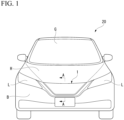
- FIG. 1 is a schematic front view of a vehicle 20 (mobile object) provided with a screen grille 1 (mobile-object-mounted display device) according to the first embodiment of the present invention.
- the vehicle 20 includes an openable and closable hood H disposed below a windshield G, headlamps L that are disposed below the hood H to be separated from each other to the left and right, and a front bumper B disposed below the headlamps L.
- the surfaces of vehicle parts such as the hood H, the headlamps L, and the front bumper B have complicated three-dimensional shapes corresponding to the type of the vehicle 20 on which they are mounted.
- an upper surface of the hood H is curved to drop downward as it goes toward the front of the vehicle.
- the front surfaces of the headlamps L and the front surface of the front bumper B are curved rearward as they go toward ends of the vehicle 20 in a vehicle width direction.
- the vehicle parts mounted on the vehicle 20 in the present embodiment are only examples, and other vehicle parts can be mounted on the vehicle 20.
- the surface shapes of the vehicle parts according to the present embodiment are also examples, and the surface shapes of the vehicle parts can be changed to a three-dimensional shape instead of a flat surface.
- not all vehicle parts need to have a three-dimensional surface shape.
- At least one surface shape of the plurality of vehicle parts has a three-dimensional shape.
- the screen grille 1 of the present embodiment is a display device that performs display of pictograms, characters, or the like toward the outside of the vehicle 20 (outside the mobile object), and as shown in FIG. 1 , it is disposed in a front part of the vehicle 20 to be surrounded by the vehicle parts having three-dimensional surfaces as described above.
- the screen grille 1 is disposed below the hood H, above the front bumper B, and between the left and right headlamps L.
- FIG. 2 is an exploded perspective view of the screen grille 1 of the present embodiment.
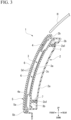
- FIG. 3 is a cross-sectional view of the screen grille 1 of the present embodiment along a vertical plane in a vehicle front-rear direction, and is a cross-sectional view along line A-A in FIG. 1 .
- the screen grille 1 of the present embodiment includes an inner member 2 (rear member), a display unit 3, a bezel 4, an outer cover 5, and a semi-transmissive layer 6.
- a side where information is presented by the display unit 3 is called a front side
- a side where the information is not displayed by the display unit 3 is called a rear side.
- the inner member 2, the display unit 3, the bezel 4, and the outer cover 5 are arranged in a front-rear direction.
- the inner member 2 is disposed on a rearmost side
- the outer cover 5 is disposed on a frontmost side.
- the inner member 2 is a member that directly or indirectly supports the display unit 3, the bezel 4, and the outer cover 5, and is disposed behind (to the rear of) the display unit 3, the bezel 4, and the outer cover 5.
- the inner member 2 is formed of a black ABS, for example.
- the inner member 2 has a plate-like portion 2a and an inner edge portion 2b provided to surround the plate-like portion 2a in the up-down direction and the left-right direction.
- the plate-like portion 2a is a plate-like portion that is disposed with a certain gap in the front-rear direction with respect to a support substrate 3a of the display unit 3, which will be described later, and covers the display unit 3 from behind.
- the plate-like portion 2a of the inner member 2 is disposed with a certain gap with respect to the support substrate 3a of the display unit 3, which will be described later.
- the plate-like portion 2a is provided with a plurality of holes 2a1 for fixing the display unit 3 with screws 7 (see FIG. 3 ).
- the display unit 3 is fixed to the inner member 2 by screwing the screws 7 inserted into the holes 2a1 into threaded portions 3b provided on the support substrate 3a of the display unit 3, which will be described later.
- the inner edge portion 2b of the inner member 2 is provided with a plurality of attachment portions 2c for attaching the inner member 2 to the vehicle body.
- the screen grille 1 of the present embodiment is fixed to the vehicle body by fixing these attachment portions 2c to the vehicle body with a screw (that is not shown) or the like.
- the inner edge portion 2b of the inner member 2 is provided with locking projections 2d for locking the outer cover 5.
- the outer cover 5 is coupled to the inner member 2 by the locking projections 2d.
- Such an inner member 2 is coupled to the outer cover 5 from behind and forms a closed space that accommodates the semi-transmissive layer 6 and the LED elements 3d with the outer cover 5 therebetween.
- the display unit 3 is a device that displays characters and pictograms under the control of a control device (that is not shown), and includes the support substrate 3a, the threaded portions 3b, a pasting sheet 3c, and the LED elements 3d (light emitting elements).
- LED means "light emitting diode.”
- the support substrate 3a is a plate-like portion to which the pasting sheet 3c is pasted on the front surface, and supports the LED elements 3d via the pasting sheet 3c. Such a support substrate 3a is disposed with a certain gap with respect to the outer cover 5.
- the threaded portions 3b are cylindrical portions provided to protrude rearward from a back surface of the support substrate 3a and a plurality of threaded portions 3b are provided to correspond to the plurality of holes 2a1 provided in the plate-like portion 2a of the inner member 2. That is, the number of threaded portions 3b and the number of holes 2a1 are the same.
- the screws 7 are screwed into these threaded portions 3b, as shown in FIG. 3 .
- the pasting sheet 3c is a sheet material having the LED elements 3d fixed on the surface side and an adhesive surface on the back surface side.
- the pasting sheet 3c is pasted on the front surface of the support substrate 3a, and fixes the LED elements 3d with respect to the support substrate 3a.
- the LED elements 3d are fixed to the front surface of the support substrate 3a via the pasting sheet 3c, and the plurality of LED elements 3d are arranged in the front-rear direction and the left-right direction. These LED elements 3d are collectively disposed in a display area R (see FIG. 2 ) provided in the central portion of the support substrate 3a when viewed from the front. Each of the LED elements 3d is coupled to a lead wire (that is not shown) for supplying power to the LED elements 3d. These lead wires are extended laterally from the display area R, drawn out via openings provided in the support substrate 3a and the plate-like portion 2a of the inner member 2, for example, and coupled to the control device. Note that it is preferable to seal the openings for passing the lead wires.
- Desired characters or pictograms are displayed in the display area R by selectively causing these LED elements 3d to emit light.
- a circuit board may be provided and the LED elements 3d may be mounted on the circuit board.
- an area in which the LED elements 3d are not disposed is provided annularly around the display area R in the support substrate 3a, and the threaded portions 3b are provided on the back surface of the area where the LED elements 3d are not provided.
- a buffer space K is provided between the LED elements 3d and the semi-transmissive layer 5.
- the buffer space K is a space that prevents the LED elements 3d from coming into contact with the semi-transmissive layer 6 even when the LED elements 3d and the outer cover 5 move relative to each other due to running vibrations of the vehicle 20. Further, by providing the buffer space K, it is possible to make it more difficult to visually recognize the LED elements 3d from the front of the outer cover 5 when the LED elements 3d are turned off.
- the bezel 4 is an annular plate member having an opening 4a in the center, and has a frame shape surrounding the display area R when viewed from the outer cover 5 side.
- the bezel 4 is an interposing member interposed between the display unit 3 and the outer cover 5, and is formed of a black ABS, for example.
- the opening 4a of the bezel 4 has a shape slightly smaller than the display area R when viewed from the front side of the outer cover 5, such that the emitting LED elements 3d can be visually recognized from the outer side of the outer cover 5.
- the bezel 4 is disposed slightly ahead of the LED elements 3d, and is disposed with a slight gap from the LED elements 3d. As shown in FIG. 3 , the bezel 4 is disposed such that an inner edge portion slightly overlaps the LED element 3d arranged at the end of the display area R when viewed from the front. Since the inner edge portion forming the opening 4a of the bezel 4 slightly overlaps the LED element 3d at the end when viewed from the front, even when a gap is provided between the bezel 4 and the LED element 3d, it is possible to prevent the outer side of the display area R from being visually recognized from the outside. That is, it is possible to prevent the outer edge portion of the display area R from being visually recognized via the opening 4a of the bezel 4 when the opening 4a of the bezel 4 is viewed from the front side of the outer cover 5.
- such a bezel 4 functions as a stopper that restricts the display unit 3 from approaching the semi-transmissive layer 6 due to running of the vehicle 20 or the like. Therefore, even when the vehicle 20 is stopped in an emergency, the bezel 4 can be prevented from approaching the semi-transmissive layer 6 of the display unit 3, the LED element 3d can be prevented from coming into contact with the semi-transmissive layer 6, and the distance between the LED elements 3d and the semi-transmissive layer 6 can be prevented from changing.
- the outer cover 5 is a transparent cover member disposed in front of the display unit 3 (that is, the LED elements 3d).
- the outer cover 5 is formed of, for example, PMMA or the like.
- Such an outer cover 5 has a transparent plate-like portion 5a and an outer edge portion 5b provided to surround the transparent plate-like portion 5a in the up-down direction and the left-right direction.
- the transparent plate-like portion 5a is a plate-like portion that is disposed in front of the LED elements 3d and covers the display unit 3 from the front.
- the transparent plate-like portion 5a of such an outer cover 5 is disposed with a certain gap with respect to the LED elements 3d (that is, display area R) of the display unit 3.
- the outer edge portion 5b of the outer cover 5 is provided with locking claws 5c for locking the outer cover 5 to the inner member 2.
- the outer cover 5 is coupled to the inner member 2 by locking the locking claws 5c with the locking projections 2d of the inner member 2. Note that a boundary portion between the outer edge portion 5b and the inner edge portion 2b is sealed as necessary. Such sealing seals the closed space between the inner member 2 and the outer cover 5, making it possible to protect the LED elements 3d from moisture or the like in the air.
- the semi-transmissive layer 6 is a layer that transmits some incident light and reflects the rest, and is provided on the rear surface of the outer cover 5. That is, the semi-transmissive layer 6 is disposed between the outer cover 5 and the display unit 3 and is disposed in front of the display unit 3 to cover the display unit 3 from the front.
- the semi-transmissive layer 6 is composed of a paint layer formed by applying paint to the rear surface of the outer cover 5 and drying the paint. Note that it is preferable that a color component reflected by the semi-transmissive layer 6 be the same color as or a similar color to those of the surrounding vehicle parts. As a result, a person viewing from the outside can visually recognize the semi-transmissive layer 6 integrally with the surrounding vehicle parts, such that the influence of the screen grille 1 on the external impression of the vehicle 20 can be further reduced.
- characters or pictograms are displayed in the display area R by selectively causing the LED elements 3d to emit light. At this time, at least a part of light emitted in the display area R is transmitted through the semi-transmissive layer 6 and reaches the outside person. Also, a part of external light is reflected by the semi-transmissive layer 6. Therefore, when characters or pictograms are not displayed in the display area R, the component of light transmitted from the outside through the semi-transmissive layer 6, reflected on the display unit 3, transmitted again through the semi-transmissive layer 6, and emitted to the outside is extremely small compared to the component of external light reflected by the semi-transmissive layer 6. Therefore, when no characters or pictograms are displayed in the display area R, it is possible to prevent the outside person from visually recognizing the display unit 3.
- the screen grille 1 of the present embodiment as described above is mounted on the vehicle 20 and performs display toward the outside of the vehicle 20. Further, the screen grille 1 of the present embodiment includes a display unit 3 that performs display by light emission, and a semi-transmissive layer 6 that is semi-transmissive and is disposed in front of the display unit 3.
- the semi-transmissive layer 6 is disposed in front of the display unit 3. Therefore, a part of external light incident on the semi-transmissive layer 6 is reflected by the semi-transmissive layer 6. Therefore, even when the display is not performed, it is possible to cause a person outside the screen grille 1 to visually recognize a color of the semi-transmissive layer 6. Accordingly, it is possible to prevent the display unit 3 from being visually recognized from an outside when the display is not performed. Therefore, according to the screen grille 1 of the present embodiment, in the screen grille 1 that is mounted on the vehicle 20 and performs display toward the outside of the vehicle 20, the influence of the screen grille 1 on the external impression of the vehicle 20 when the display is not performed can be reduced.
- the screen grille 1 of the present embodiment includes a transparent outer cover 5 that is disposed in front of the display unit 3 and covers the display unit 3 from the front, and the semi-transmissive layer 6 is disposed between the outer cover 5 and the display unit 3. Therefore, according to the screen grille 1 of the present embodiment, the semi-transmissive layer 6 is disposed between the outer cover 5 and the display unit 3, and the semi-transmissive layer 6 can be protected by the outer cover 5 from wind and rain.
- the semi-transmissive layer 6 is provided on the rear surface of the outer cover 5. Therefore, the semi-transmissive layer 6 can be supported without separately providing a member for supporting the semi-transmissive layer 6.
- the screen grille 1 of the present embodiment includes an inner member 2 that is coupled to the outer cover 5 from behind and forms a closed space that accommodates the semi-transmissive layer 6 with the outer cover 5 therebetween. Therefore, it is possible to prevent external moisture or the like from entering the space between the inner member 2 and the outer cover 5, thereby protecting the semi-transmissive layer 6 and the LED elements 3d from moisture or the like.
- the semi-transmissive layer 6 is composed of a paint layer formed of paint. Therefore, the semi-transmissive layer 6 can be easily formed by drying the applied paint.
- a buffer space K is provided between the display unit 3 and the semi-transmissive layer 6. Therefore, even when the LED elements 3d and the outer cover 5 move relative to each other due to running vibrations of the vehicle 20 or the like, the LED elements 3d can be prevented from coming into contact with the semi-transmissive layer 6. Further, by providing the buffer space K, it is possible to make it difficult to visually recognize the LED elements 3d from the front of the outer cover 5 when the LED elements 3d are turned off.
- the screen grille 1 of the present embodiment includes a bezel 4 interposed between the display unit 3 and the semi-transmissive layer 6, and the bezel 4 is disposed to avoid at least a part of the display area of the display unit 3 when viewed from the front of the semi-transmissive layer 6.
- a bezel 4 functions as a stopper that restricts the display unit 3 from approaching the outer cover 5 due to running of the vehicle 20 or the like. Therefore, even when the vehicle 20 is stopped in an emergency, the bezel 4 can prevent the display unit 3 from approaching the outer cover 5, the LED element 3d can be prevented from coming into contact with the semi-transmissive layer 6, and the distance between the LED elements 3d and the outer cover 5 can be prevented from changing.
- the bezel 4 has a frame shape surrounding the display area when viewed from the front of the semi-transmissive layer 6. Therefore, the bezel 4 can hide the up-down direction and the left-right direction of the area where the LED elements 3d are disposed, and the lead wires and the like coupled to the LED elements 3d can be hidden. That is, the bezel 4 can hide the outer edge portions extending in the up-down direction and the left-right direction of the area where the LED elements 3d are disposed, and the lead wires and the like coupled to the LED elements 3d can be hidden. Therefore, the screen grille 1 of the present embodiment can improve the external impression of the screen grille 1 by including the bezel 4.
- FIG. 4 is a cross-sectional view of a screen grille 1A of the present embodiment along a vertical plane in the front-rear direction of the vehicle.
- the semi-transmissive layer 6 has an ink layer 6a formed of ink and a film layer 6b covering the ink layer 6a from behind.
- the ink layer 6a is a layer that transmits a part of the incident light and reflects the rest, and is formed by printing ink on the film layer 6b by printing or the like and drying the ink.
- the film layer 6b is a transparent supporting member that supports the ink layer 6a. Note that the film layer 6b may also be a layer that transmits a part of the incident light and reflects the rest.
- the semi-transmissive layer 6 can be easily formed by printing ink on the film layer 6b and attaching the film layer 6b to the rear surface of the outer cover 5 together.
- the present invention is not limited to this.
- an organic EL (that is, electroluminescence) element or the like can be used as the light emitting element.
- the present invention is not limited to this.
- the mobile object on which the mobile-object-mounted device of the present invention is mounted is the vehicle 20.
- the present invention is not limited to this.
- the configuration including the outer cover 5 has been described.
- the present invention is not limited to this.
- the semi-transmissive layer 6 has weather resistance
- the semi-transmissive layer 6 has weather resistance
- the semi-transmissive layer 6 may also be a semi-transparent plastic sheet. Such a plastic sheet can be molded by injection molding, extrusion, or the like.
- the semi-transmissive layer 6 may be a semi-transparent metal layer. Such a metal layer can be produced by semi-transparent plating, vapor deposition, sputtering, or the like.
- the bezel 4 may be bilaterally symmetrical to overlap at least one of the upper edge portion, lower edge portion, left edge portion, and right edge portion of the display area R.
- the shape of the bezel 4 may be a shape that overlaps only the upper edge portion, a shape that overlaps only the lower edge portion, a shape that overlaps only the left and right sides, and a shape that overlaps either the upper edge portion or the lower edge portion and both the left and right sides.
- the bezel 4 functions as a stopper that restricts the display unit 3 from approaching the outer cover 5.
- the bezel 4 can prevent the outer side of the display area R from being visually recognized from the outside.
- the bezel 4 functions as the stopper when the bezel 4 overlaps with at least one of the upper edge portion, the lower edge portion, the left edge portion, and the right edge portion of the display area R, it is preferable that the bezel 4 be bilaterally symmetrical when viewed from the front of the vehicle in terms of aesthetics of the vehicle.
- the semi-transmissive layer is disposed in front of the display unit. Therefore, a part of external light incident on the semi-transmissive layer is reflected by the semi-transmissive layer. Therefore, even when the display is not performed, it is possible to cause a person outside the mobile-object-mounted display device to visually recognize a color of the semi-transmissive layer. Accordingly, it is possible to prevent the display unit from being visually recognized from the outside when the display is not performed. Therefore, according to the present invention, it is possible to reduce the influence on the external impression of the mobile object when display is not performed in a mobile-object-mounted display device which is mounted on the mobile object and performs display toward the outside of the mobile object.
Landscapes
- Engineering & Computer Science (AREA)
- Mechanical Engineering (AREA)
- Physics & Mathematics (AREA)
- General Physics & Mathematics (AREA)
- Theoretical Computer Science (AREA)
- Business, Economics & Management (AREA)
- Accounting & Taxation (AREA)
- Marketing (AREA)
- Illuminated Signs And Luminous Advertising (AREA)
- Fittings On The Vehicle Exterior For Carrying Loads, And Devices For Holding Or Mounting Articles (AREA)
- Devices For Indicating Variable Information By Combining Individual Elements (AREA)
Applications Claiming Priority (2)
| Application Number | Priority Date | Filing Date | Title |
|---|---|---|---|
| JP2020139769A JP2022035437A (ja) | 2020-08-21 | 2020-08-21 | 移動体搭載表示装置 |
| PCT/JP2021/030663 WO2022039271A1 (ja) | 2020-08-21 | 2021-08-20 | 移動体搭載表示装置 |
Publications (1)
| Publication Number | Publication Date |
|---|---|
| EP4201748A1 true EP4201748A1 (de) | 2023-06-28 |
Family
ID=80323016
Family Applications (1)
| Application Number | Title | Priority Date | Filing Date |
|---|---|---|---|
| EP21858414.2A Withdrawn EP4201748A1 (de) | 2020-08-21 | 2021-08-20 | An einem mobilen körper montierte anzeigevorrichtung |
Country Status (5)
| Country | Link |
|---|---|
| US (1) | US20230347814A1 (de) |
| EP (1) | EP4201748A1 (de) |
| JP (1) | JP2022035437A (de) |
| CN (1) | CN115867461A (de) |
| WO (1) | WO2022039271A1 (de) |
Families Citing this family (1)
| Publication number | Priority date | Publication date | Assignee | Title |
|---|---|---|---|---|
| JP7812735B2 (ja) * | 2022-05-20 | 2026-02-10 | トヨタ自動車株式会社 | 車外表示器の防水構造 |
Family Cites Families (11)
| Publication number | Priority date | Publication date | Assignee | Title |
|---|---|---|---|---|
| JPS59134301U (ja) * | 1983-02-28 | 1984-09-08 | 日産自動車株式会社 | 自動車の灯具 |
| JPS60193937A (ja) | 1984-03-16 | 1985-10-02 | Toyo Soda Mfg Co Ltd | オレフインの水和によるアルコ−ルの製造方法 |
| JP4239839B2 (ja) * | 2004-02-02 | 2009-03-18 | 市光工業株式会社 | 車両用アウトサイドミラー装置 |
| JP5363235B2 (ja) * | 2009-08-04 | 2013-12-11 | 株式会社小糸製作所 | 車両用灯具 |
| JP2014120349A (ja) * | 2012-12-17 | 2014-06-30 | Koito Mfg Co Ltd | 車両用灯具 |
| JP2016175565A (ja) * | 2015-03-20 | 2016-10-06 | ダイキョーニシカワ株式会社 | 車両用バックドア |
| WO2016196540A1 (en) * | 2015-06-02 | 2016-12-08 | Corning Incorporated | Aesthetic surface and display device with such a surface |
| JP6917378B2 (ja) * | 2015-09-17 | 2021-08-11 | ファゾム・オプティクス・インコーポレイテッド | マルチビューディスプレイ並びに関連するシステム及び方法 |
| JP2018058412A (ja) * | 2016-10-03 | 2018-04-12 | 株式会社小糸製作所 | 車両用灯具 |
| JP2018100011A (ja) * | 2016-12-21 | 2018-06-28 | 三菱自動車工業株式会社 | 車両用前照灯の凍結防止装置 |
| JP7313657B2 (ja) | 2019-02-27 | 2023-07-25 | 株式会社バイオエコーネット | 耳式体温計 |
-
2020
- 2020-08-21 JP JP2020139769A patent/JP2022035437A/ja active Pending
-
2021
- 2021-08-20 US US18/021,939 patent/US20230347814A1/en not_active Abandoned
- 2021-08-20 CN CN202180050444.4A patent/CN115867461A/zh active Pending
- 2021-08-20 EP EP21858414.2A patent/EP4201748A1/de not_active Withdrawn
- 2021-08-20 WO PCT/JP2021/030663 patent/WO2022039271A1/ja not_active Ceased
Also Published As
| Publication number | Publication date |
|---|---|
| CN115867461A (zh) | 2023-03-28 |
| WO2022039271A1 (ja) | 2022-02-24 |
| JP2022035437A (ja) | 2022-03-04 |
| US20230347814A1 (en) | 2023-11-02 |
Similar Documents
| Publication | Publication Date | Title |
|---|---|---|
| US12305825B2 (en) | Mobile-object-mounted display device | |
| JP5961053B2 (ja) | 車両用リアパネル | |
| US9669754B2 (en) | Turn signal lamp | |
| US20220221121A1 (en) | Lighting apparatus for vehicle and method of manufacturing the same | |
| US9789814B2 (en) | Indirect light-emitting front grill | |
| US8794806B2 (en) | Light module | |
| US11572009B2 (en) | Covering device, body part and motor vehicle | |
| US10661705B2 (en) | Exterior rearview mirror with turn signal unit | |
| JP2009143520A (ja) | 車両用外装部品 | |
| EP4201748A1 (de) | An einem mobilen körper montierte anzeigevorrichtung | |
| JP2014094656A (ja) | 加飾照明装置 | |
| US10634908B2 (en) | Display device and display device main body including first and second emitting portions | |
| JPH09150648A (ja) | 車両用表示装置 | |
| US20240159372A1 (en) | Lighting Device for a Motor Vehicle | |
| US20220075190A1 (en) | Head-up display | |
| RU2639931C1 (ru) | Световое информационное табло с заменяемой лицевой панелью, встроенное в противосолнечный козырек автомобиля | |
| CN114667456B (zh) | 具有车顶外覆层和环境传感器的车顶模块 | |
| JP6046368B2 (ja) | 車両用表示装置 | |
| US12085248B2 (en) | Vehicle lamp | |
| US20240308423A1 (en) | Lighting display device for vehicle | |
| KR102690303B1 (ko) | 후/측방 운전자 및 차량 정보 알림용 디스플레이 장치 | |
| US20260036276A1 (en) | Lighting device for vehicle | |
| JP2025078451A (ja) | 車両内装構造 | |
| JP2001018711A (ja) | 自動車用窓ガラスの警告灯取付構造 |
Legal Events
| Date | Code | Title | Description |
|---|---|---|---|
| STAA | Information on the status of an ep patent application or granted ep patent |
Free format text: STATUS: THE INTERNATIONAL PUBLICATION HAS BEEN MADE |
|
| PUAI | Public reference made under article 153(3) epc to a published international application that has entered the european phase |
Free format text: ORIGINAL CODE: 0009012 |
|
| STAA | Information on the status of an ep patent application or granted ep patent |
Free format text: STATUS: REQUEST FOR EXAMINATION WAS MADE |
|
| 17P | Request for examination filed |
Effective date: 20230221 |
|
| AK | Designated contracting states |
Kind code of ref document: A1 Designated state(s): AL AT BE BG CH CY CZ DE DK EE ES FI FR GB GR HR HU IE IS IT LI LT LU LV MC MK MT NL NO PL PT RO RS SE SI SK SM TR |
|
| DAV | Request for validation of the european patent (deleted) | ||
| DAX | Request for extension of the european patent (deleted) | ||
| STAA | Information on the status of an ep patent application or granted ep patent |
Free format text: STATUS: THE APPLICATION HAS BEEN WITHDRAWN |
|
| 18W | Application withdrawn |
Effective date: 20240613 |