EP4201625B1 - Method and plant for producing concrete - Google Patents
Method and plant for producing concrete Download PDFInfo
- Publication number
- EP4201625B1 EP4201625B1 EP22215150.8A EP22215150A EP4201625B1 EP 4201625 B1 EP4201625 B1 EP 4201625B1 EP 22215150 A EP22215150 A EP 22215150A EP 4201625 B1 EP4201625 B1 EP 4201625B1
- Authority
- EP
- European Patent Office
- Prior art keywords
- granular materials
- storage
- transport
- conveyor belt
- hoppers
- Prior art date
- Legal status (The legal status is an assumption and is not a legal conclusion. Google has not performed a legal analysis and makes no representation as to the accuracy of the status listed.)
- Active
Links
Images


Classifications
-
- B—PERFORMING OPERATIONS; TRANSPORTING
- B28—WORKING CEMENT, CLAY, OR STONE
- B28C—PREPARING CLAY; PRODUCING MIXTURES CONTAINING CLAY OR CEMENTITIOUS MATERIAL, e.g. PLASTER
- B28C7/00—Controlling the operation of apparatus for producing mixtures of clay or cement with other substances; Supplying or proportioning the ingredients for mixing clay or cement with other substances; Discharging the mixture
- B28C7/04—Supplying or proportioning the ingredients
- B28C7/0481—Plant for proportioning, supplying or batching
-
- B—PERFORMING OPERATIONS; TRANSPORTING
- B28—WORKING CEMENT, CLAY, OR STONE
- B28C—PREPARING CLAY; PRODUCING MIXTURES CONTAINING CLAY OR CEMENTITIOUS MATERIAL, e.g. PLASTER
- B28C7/00—Controlling the operation of apparatus for producing mixtures of clay or cement with other substances; Supplying or proportioning the ingredients for mixing clay or cement with other substances; Discharging the mixture
- B28C7/0046—Storage or weighing apparatus for supplying ingredients
- B28C7/0053—Storage containers, e.g. hoppers, silos, bins
- B28C7/0061—Storage container plant
-
- B—PERFORMING OPERATIONS; TRANSPORTING
- B28—WORKING CEMENT, CLAY, OR STONE
- B28C—PREPARING CLAY; PRODUCING MIXTURES CONTAINING CLAY OR CEMENTITIOUS MATERIAL, e.g. PLASTER
- B28C7/00—Controlling the operation of apparatus for producing mixtures of clay or cement with other substances; Supplying or proportioning the ingredients for mixing clay or cement with other substances; Discharging the mixture
- B28C7/0046—Storage or weighing apparatus for supplying ingredients
- B28C7/0053—Storage containers, e.g. hoppers, silos, bins
- B28C7/0069—Storage containers, e.g. hoppers, silos, bins having compartments
-
- B—PERFORMING OPERATIONS; TRANSPORTING
- B28—WORKING CEMENT, CLAY, OR STONE
- B28C—PREPARING CLAY; PRODUCING MIXTURES CONTAINING CLAY OR CEMENTITIOUS MATERIAL, e.g. PLASTER
- B28C7/00—Controlling the operation of apparatus for producing mixtures of clay or cement with other substances; Supplying or proportioning the ingredients for mixing clay or cement with other substances; Discharging the mixture
- B28C7/04—Supplying or proportioning the ingredients
- B28C7/06—Supplying the solid ingredients, e.g. by means of endless conveyors or jigging conveyors
- B28C7/067—Supplying the solid ingredients, e.g. by means of endless conveyors or jigging conveyors by means of stationary hoppers, chambers or bins from which the material is fed gravitationally, e.g. having agitating means therein
Definitions
- the present invention relates to a method and an installation for manufacturing concrete.
- Concrete manufacturing methods comprising transferring quantities of granular materials having different particle sizes into separate storage hoppers, discharging metered quantities of at least one of said granular materials from at least one of said storage hoppers onto a conveying means, transporting these metered quantities by said conveying means to a conveyor belt which conveys them to the top of a mixing stage, mixing, in this mixing stage, said metered quantities, conveyed, of at least one of said granular materials with hydraulic binder, water and possible additives, to form a pasty mass of concrete, and discharging said pasty mass of concrete from the mixing stage, for its exploitation.
- an installation in a known manner which comprises storage hoppers for receiving granular materials having different particle sizes, which are provided with an upper loading opening and a lower, closable discharge orifice, a transport means onto which metered quantities of granular materials are discharged from said storage hoppers, a conveyor belt onto which said transport means brings said metered quantities of granular materials, and a mixing stage having an inlet, where said conveyor belt carries said metered quantities of granular materials, means for supplying hydraulic binder, water and possible additives and a closable outlet for discharging a pasty mass of concrete.
- mixing stage is meant all the elements and devices which allow mixing of material, and therefore not only the mixer, but also the mixer feed systems.
- this mixing stage has the form of a tower, the upper level of which comprises scales for water, cement and any additives, as well as an aggregate tank for receiving the already dosed quantities of granular materials and the lower level of which consists of the mixer itself.
- the scales and the aggregate tank can empty simultaneously into the mixer.
- Concrete manufacturing facilities are used to supply products of several types, such as Bénor concretes that comply with European standards or rich concretes known as "on composition", lean concretes, or various mixtures based on cement and aggregates such as stabilized stone, stabilized sand, screeds, specific concretes (road, cavernous, colloidal, etc.). Special admixtures are sometimes required and there is an increasing demand for recycling certain previously used materials into concrete.
- Concrete is mixed in a mixing tank called a batching tank, and production is therefore carried out in batches which are obtained every 20 to 50 seconds, then poured into mixing vehicles, for example concrete mixer trucks, each concrete mixer truck being able to contain for example 3 batches. This pouring can also take place in dump trucks, flatbed trucks or even simple trailers attached to cars.
- mixing vehicles for example concrete mixer trucks, each concrete mixer truck being able to contain for example 3 batches. This pouring can also take place in dump trucks, flatbed trucks or even simple trailers attached to cars.
- a method for manufacturing concrete comprising transferring quantities of granular materials having different particle sizes into separate storage hoppers, discharging metered quantities of at least one of said granular materials from at least one of said hoppers of a first series of storage hoppers onto a first conveyor belt which, as a means of transport, runs in one direction, in a first direction, discharging metered quantities of at least one of said granular materials from at least one of said hoppers of a second series of storage hoppers onto a second conveyor belt which, as a means of transport, runs in said direction, in a second direction opposite to the first, and transporting these metered quantities of granular materials by said conveyor belts to a conveyor belt which conveys them to the top of two separate mixing towers, in each of which these granular materials are mixed with binder hydraulic, water and possible adjuvants, to form a pasty mass of concrete, to be discharged for its exploitation, said transport step comprising selectably a
- the present invention aims to solve these problems and to propose a method and a concrete manufacturing installation which make it possible to improve the performance of concrete production installations and which allow great flexibility in the manufacturing of different concretes in the same installation.
- the aforementioned granular materials also called aggregates, which include sands, gravels, and gravels of predetermined granulometric sizes, can be brought to the mixers in successive mixtures that are easily adaptable.
- the conveyor belt can be fed by one or more conveyor belts, each supplied from one or more storage hoppers, which substantially multiplies the number of different granular mixtures that can be conveyed to the aggregate tank of one of the mixing towers or the other.
- the quantity of hydraulic binder, water or admixture can be adjusted independently according to demand. Two concrete trucks can therefore collect two concretes of different qualities from the bottom of the mixers almost simultaneously.
- said transfer step comprises pouring at least one of the granular materials into at least one storage hopper from a carrier vehicle.
- a carrier vehicle it is advantageous to envisage, for example, dump trucks.
- said transfer step comprises an intermediate storage of one of said granular materials opposite each storage hopper, and a loading thereof by simple pushing of the granular material.
- the method according to the invention comprises a primary storage of said granular materials, separately, at a distance from said storage hoppers, and at the same level as the intermediate storage and said transfer step comprises a step of preliminary movement of the granular material from the primary storage directly to the hoppers or to the intermediate storage, prior to loading the hoppers.
- the method comprises weighing the granular materials discharged onto the conveyor belts. Weighing each conveyor belt during each aforementioned discharge onto it of one of said granular materials allows metering of the quantities discharged from the storage hoppers.
- an impact plate is arranged between the two discharge ends of the two conveyor belts so as to be able to pivot freely about an axis perpendicular to the direction of travel of the conveyor belts, the upper end of the conveyor belt opening onto an inclined, pivoting guide plate, which directs the metered quantities of granular materials into an aggregate tank of one of the mixing towers or into an aggregate tank of the other of said mixing towers, the installation further comprising control means which are arranged to produce an opening or a closing of the discharge orifice of one or more hoppers of one or both series of storage hoppers and a setting in motion of one of the conveyor belts or both simultaneously so as to allow a simultaneous supply of the granular materials to the conveyor belt from the first and second conveyor belts or a stopping of this supply from one of the two conveyor belts and to control a pivoting the pivoting guide plate so as to direct the granular materials into the aggregate tank of one or other of the mixing towers.
- control means are integrated into a remote control unit.
- the moving conveyor belts are therefore arranged so as to move towards a lower end of the conveyor belt. They are, in a selected manner, loaded or not with one or more granular materials.
- the impact plate can pivot freely under the thrust of the aggregate flows discharged from the left and/or right by the conveyor belts. In this way it directs in at any time and in a quasi-vertical manner this or these flows towards the lower end of the conveyor belt.
- this impact plate pivots to the opposite side under their thrust which has the effect of preventing the granular materials from overflowing beyond the conveyor belt.
- the impact plate When granular materials are discharged from both conveyor belts simultaneously, the impact plate remains static in a vertical position and it has the additional effect of channeling the flows and thus preventing them from interacting with each other in an undesirable manner.
- the conveyor belt runs obliquely from this lower end to a high end located above the upper inlet openings of the mixing towers, and the high end of the conveyor belt opens onto an inclined, pivoting guide plate, which directs the metered quantities of granular materials directly into the aggregate tank of one or other of the said mixing towers.
- the installation comprises an intermediate storage area in front of the upper loading opening of each of the storage hoppers.
- These intermediate storage areas can form a buffer storage space before storage in the hoppers. They can also be used to accommodate a carrier vehicle capable of directly pouring granular material into the corresponding hopper, when the latter is empty. Dump trucks can then pour their contents directly into the hopper, thus avoiding costly handling by a loader machine which still has to push the stored material.
- the installation further comprises primary storage areas for the granular materials, located at a distance from the hoppers storage, and the primary storage areas and the intermediate storage areas are arranged at the same level which is equal to or higher than the upper inlet openings of the storage hoppers.
- these primary storage and intermediate storage areas are arranged on a single platform on which, for example, several loading machines can circulate simultaneously and carry out a transfer of each of the granular materials to its intermediate storage area(s), as required.
- These same loading machines are also capable of pushing the granular materials from their intermediate storage area into their storage hopper.
- an access ramp for trucks, or any other common means of transport can be considered. This general arrangement allows loading of each hopper independently of the others as required and therefore a faster and easier supply of the installation.
- At least one storage hopper comprises an upper part opening onto a lower part comprising at least two separate compartments each provided with a lower discharge opening, closable independently of the discharge opening of the other compartment.
- This arrangement facilitates precisely regulated metering of the mixture of granular materials to be fed by the respective conveyor belt to the conveyor belt and allows an adjusted discharge speed.
- one or two of the lower discharge openings are opened.
- the openings of the aforementioned compartments can be closed by conventional means such as, for example, flaps for gravel and extractor belts for sand.
- the illustrated installation comprises a platform 1, to which dump trucks containing granular materials can reach via an access ramp 2.
- Several primary storage areas 3 are provided on one side of the platform, in housings separated by partitions 4.
- granular materials such as sand, gravel, gravel of various granulometric sizes, naturally at a rate of only one material per housing.
- These granular materials have granulometric sizes corresponding to common standards, for example 0/80, 0/63, 32/63, 63/150, 0/20, 0/6.3, 6.3/20 etc. which will then be used independently depending on the finished product to be produced.
- These standards correspond to the mesh openings of the screens and are to be expressed in mm.
- each five storage hoppers 5 and 5' respectively, each of which is aligned above a conveyor belt 6 and 6' respectively.
- these hoppers 5, 5' each have an upper loading opening 7 and respectively 7', which, in the example illustrated, is located at the level of the platform 1.
- Intermediate storage areas 8 and respectively 8' are arranged on the platform 1 in front of each storage hopper, being separated from each other by partitions 9 and respectively 9'. These intermediate storage areas 8, 8' serve as buffers between the primary storage areas 3 and the storage hoppers 5, 5'.
- Each storage hopper comprises, in the example illustrated, an upper part, which, in the example illustrated, comprises two vertical opposite walls 11, 12, and respectively 11', 12', which are arranged perpendicular to their conveyor belt 6, 6', and two walls inclined towards each other 13, 14 and respectively 13', 14'.
- This upper part opens into two separate compartments 15, 16 and respectively 15', 16' which each have the shape of an inverted pyramid and which each have a discharge orifice 17 and respectively 17', which is closable.
- the discharge opening is closed by a valve 18. This valve closes the corresponding compartment of the hopper if the latter is not to see the granular material it contains discharged or it opens it otherwise.
- valve 18 The passage of the valve 18 from an open position to a closed position or vice versa is carried out using any usual means known to those skilled in the art. In the example illustrated it is opened using two jacks 28 controlled remotely from a control unit 19.
- the hopper contains a fine granular material, such as sand, it may be advantageous to regulate its discharge, not by a valve, but by an extractor belt known per se for this purpose, which can also be set in motion by the control unit 19.
- the conveyor belts 6 and 6' are arranged so as to travel horizontally towards each other in the same horizontal direction, but in opposite directions F1, F2, towards a lower end 21 of the conveyor belt 20.
- the two conveyor belts 6 and 6' simultaneously discharge aggregates over the lower end of the conveyor belt 20.
- the aggregates, arriving at a certain speed, are stopped in their course by an impact plate 30 which pivots freely.
- the impact plate is in a vertical position, because it is subjected to the thrust of the material flows which come simultaneously from the conveyor belt 6 and the conveyor belt 6'.
- the pivoting impact plate As the pivoting impact plate is located between the two ends of the two conveyor belts 6, 6', it has the effect of causing an almost vertical fall of the aggregates from each of the conveyor belts towards the conveyor belt 20.
- the impact plate 30 can, under the thrust of the material, pivot along one of the arrows F3 or F4, in thus preventing aggregates from overflowing beyond the conveyor belt.
- Each mixer is provided in a known manner with various feeding means, such as scales, for hydraulic binder 25, 25', water 26, 26' and possible additives 27, 27', such as plasticizers.
- These mixers are of course also provided with a lower closable outlet opening for discharging a pasty mass of concrete, for example into mixer trucks brought under the mixers.
Landscapes
- Chemical & Material Sciences (AREA)
- Dispersion Chemistry (AREA)
- Preparation Of Clay, And Manufacture Of Mixtures Containing Clay Or Cement (AREA)
- Filling Or Emptying Of Bunkers, Hoppers, And Tanks (AREA)
Description
La présente invention est relative à un procédé et à une installation de fabrication de béton.The present invention relates to a method and an installation for manufacturing concrete.
On connaît des procédés de fabrication de béton comprenant un transfert de quantités de matériaux granulaires présentant différentes tailles granulométriques dans des trémies de stockage séparées, un déversement de quantités dosées d'au moins un desdits matériaux granulaires à partir d'au moins une desdites trémies de stockage sur un moyen de transport, un transport de ces quantités dosées par ledit moyen de transport vers une bande convoyeuse qui les achemine en haut d'un étage de malaxage, un malaxage, dans cet étage de malaxage, desdites quantités dosées, acheminées, d'au moins un desdits matériaux granulaires avec du liant hydraulique, de l'eau et d'éventuels adjuvants, pour former une masse pâteuse de béton, et un déchargement de ladite masse pâteuse de béton hors de l'étage de malaxage, pour son exploitation.Concrete manufacturing methods are known comprising transferring quantities of granular materials having different particle sizes into separate storage hoppers, discharging metered quantities of at least one of said granular materials from at least one of said storage hoppers onto a conveying means, transporting these metered quantities by said conveying means to a conveyor belt which conveys them to the top of a mixing stage, mixing, in this mixing stage, said metered quantities, conveyed, of at least one of said granular materials with hydraulic binder, water and possible additives, to form a pasty mass of concrete, and discharging said pasty mass of concrete from the mixing stage, for its exploitation.
Pour la mise en œuvre d'un tel procédé on prévoit de manière connue une installation qui comprend des trémies de stockage pour recevoir des matériaux granulaires présentant différentes tailles granulométriques, qui sont munies d'une ouverture supérieure de chargement et d'un orifice inférieur de déversement, obturable, un moyen de transport sur lequel sont déversées des quantités dosées de matériaux granulaires à partir desdites trémies de stockage, une bande convoyeuse sur laquelle ledit moyen de transport amène lesdites quantités dosées de matériaux granulaires, et un étage de malaxage présentant une entrée, où ladite bande convoyeuse achemine lesdites quantités dosées de matériaux granulaires, des moyens d'alimentation en liant hydraulique, en eau et en d'éventuels adjuvants et une sortie obturable pour décharger une masse pâteuse de béton.For the implementation of such a method, an installation is provided in a known manner which comprises storage hoppers for receiving granular materials having different particle sizes, which are provided with an upper loading opening and a lower, closable discharge orifice, a transport means onto which metered quantities of granular materials are discharged from said storage hoppers, a conveyor belt onto which said transport means brings said metered quantities of granular materials, and a mixing stage having an inlet, where said conveyor belt carries said metered quantities of granular materials, means for supplying hydraulic binder, water and possible additives and a closable outlet for discharging a pasty mass of concrete.
Par étage de malaxage, il faut entendre suivant l'invention l'ensemble des éléments et dispositifs qui permettent un malaxage de matériau, et donc non seulement le malaxeur, mais aussi les systèmes d'alimentation du malaxeur. D'une manière usuelle, cet étage de malaxage a la forme d'une tour, dont le niveau supérieur comprend des bascules à eau, à ciment et à adjuvants éventuels, ainsi qu'un réservoir à agrégats pour recevoir les quantités déjà dosées de matériaux granulaires et dont le niveau inférieur consiste en le malaxeur lui-même. Lorsque le malaxeur est vide, les bascules et le réservoir à agrégats peuvent se vider simultanément dans le malaxeur.By mixing stage, according to the invention, is meant all the elements and devices which allow mixing of material, and therefore not only the mixer, but also the mixer feed systems. Typically, this mixing stage has the form of a tower, the upper level of which comprises scales for water, cement and any additives, as well as an aggregate tank for receiving the already dosed quantities of granular materials and the lower level of which consists of the mixer itself. When the mixer is empty, the scales and the aggregate tank can empty simultaneously into the mixer.
Les installations de fabrication de béton sont utilisées pour fournir des produits de plusieurs natures, comme par exemple des bétons Bénor conformes aux normes européennes ou des bétons riches dits "sur composition", des bétons maigres, ou des mélanges divers à base de ciment et d'agrégats comme des empierrements stabilisés, des sables stabilisés, des chapes, des bétons spécifiques (routiers, caverneux, colloïdaux, etc). Des adjuvants particuliers sont parfois demandés et de plus en plus il est recherché de pouvoir recycler dans les bétons certaines matières déjà préalablement exploitées.Concrete manufacturing facilities are used to supply products of several types, such as Bénor concretes that comply with European standards or rich concretes known as "on composition", lean concretes, or various mixtures based on cement and aggregates such as stabilized stone, stabilized sand, screeds, specific concretes (road, cavernous, colloidal, etc.). Special admixtures are sometimes required and there is an increasing demand for recycling certain previously used materials into concrete.
Les bétons sont malaxés dans une cuve de malaxage appelée gâche, et la production est donc effectuée par gâchées qui sont obtenues toutes les 20 à 50 secondes, puis déversées dans des véhicules malaxeurs, par exemple des camions toupie, chaque camion toupie pouvant contenir par exemple 3 gâchées. Ce déversement peut aussi avoir lieu dans des camions bennes, des camions plateau ou encore de simples remorques attachées à des voitures.Concrete is mixed in a mixing tank called a batching tank, and production is therefore carried out in batches which are obtained every 20 to 50 seconds, then poured into mixing vehicles, for example concrete mixer trucks, each concrete mixer truck being able to contain for example 3 batches. This pouring can also take place in dump trucks, flatbed trucks or even simple trailers attached to cars.
Ces installations montrent généralement une performance limitée. Elles ne permettent pas d'augmenter ou de diminuer rapidement la production d'un béton, en fonction de la demande, et surtout elles ne permettent pas un passage aisé et rapide de la fabrication de gâchées d'une composition à celle de gâchées d'une autre composition.These installations generally show limited performance. They do not allow for rapid increase or decrease the production of concrete, depending on demand, and above all they do not allow an easy and rapid transition from the production of batches of one composition to that of batches of another composition.
En vue de résoudre ce type de problèmes il a déjà été prévu un procédé de fabrication de béton, comprenant un transfert de quantités de matériaux granulaires présentant différentes tailles granulométriques dans des trémies de stockage séparées, un déversement de quantités dosées d'au moins un desdits matériaux granulaires à partir d'au moins une desdites trémies d'une première série de trémies de stockage sur une première bande transporteuse qui, comme moyen de transport, défile suivant une direction, dans un premier sens, un déversement de quantités dosées d'au moins un desdits matériaux granulaires à partir d'au moins une desdites trémies d'une deuxième série de trémies de stockage sur une deuxième bande transporteuse qui, comme moyen de transport, défile suivant ladite direction, dans un deuxième sens opposé au premier, et un transport de ces quantités dosées de matériaux granulaires par lesdites bandes transporteuses vers une bande convoyeuse qui les achemine en haut de deux tours de malaxage séparées, dans chacune desquelles ces matériaux granulaires sont mélangés avec du liant hydraulique, de l'eau et d'éventuels adjuvants, pour former une masse pâteuse de béton, à décharger pour son exploitation, ladite étape de transport comprenant de manière sélectionnable une alimentation de la bande convoyeuse par la première bande transporteuse ou une alimentation de la bande convoyeuse par la deuxième bande transporteuse (voir
Ce dernier procédé permet de réaliser de façon simplifiée plusieurs bétons de compositions différentes successivement et permet donc d'accélérer la production globale de l'installation mettant en œuvre ce procédé. Il manque toutefois encore de souplesse et présente des inconvénients difficilement surmontables au niveau de la répartition des matériaux granulaires dans l'un ou l'autre des malaxeurs.This latter process makes it possible to produce several concretes of different compositions successively in a simplified manner and therefore speeds up the overall production of the installation using this process. However, it still lacks flexibility and has disadvantages that are difficult to overcome in terms of the distribution of granular materials in one or other of the mixers.
La présente invention a pour but de résoudre ces problèmes et de proposer un procédé et une installation de fabrication de béton qui permettent d'améliorer la performance des installations de production de béton et qui autorisent une grande souplesse dans la fabrication de bétons différents dans une même installation.The present invention aims to solve these problems and to propose a method and a concrete manufacturing installation which make it possible to improve the performance of concrete production installations and which allow great flexibility in the manufacturing of different concretes in the same installation.
Il est ainsi prévu, suivant l'invention, un procédé de fabrication de béton suivant la revendication 1.Thus, according to the invention, a method of manufacturing concrete according to
Ce procédé permet, en fonction des diverses commandes, non seulement d'accroître ou de réduire très significativement et très rapidement la capacité de production de l'installation, mais aussi de fournir rapidement des gâchées de bétons de compositions différentes successivement ou même simultanément. En effet, les matériaux granulaires susdits, appelés aussi granulats, qui comprennent des sables, des gravillons, et des graviers de tailles granulométriques prédéterminées, peuvent être amenés aux malaxeurs en mélanges successifs facilement adaptables. La bande convoyeuse peut, elle, être alimentée par une ou plusieurs bandes transporteuses, elles-mêmes approvisionnées chacune depuis une ou plusieurs trémies de stockage, ce qui multiplie substantiellement le nombre de mélanges granulaires différents que l'on peut acheminer au réservoir à agrégats de l'une des tours de malaxage ou de l'autre. Et, dans chaque malaxeur, la quantité de liant hydraulique, d'eau ou d'adjuvant peut être adaptée indépendamment en fonction de la demande. Deux camions toupies peuvent donc récolter au bas des malaxeurs presque simultanément deux bétons de qualités différentes.This process allows, depending on the various orders, not only to increase or reduce very significantly and very quickly the production capacity of the installation, but also to quickly supply batches of concrete of different compositions successively or even simultaneously. Indeed, the aforementioned granular materials, also called aggregates, which include sands, gravels, and gravels of predetermined granulometric sizes, can be brought to the mixers in successive mixtures that are easily adaptable. The conveyor belt can be fed by one or more conveyor belts, each supplied from one or more storage hoppers, which substantially multiplies the number of different granular mixtures that can be conveyed to the aggregate tank of one of the mixing towers or the other. And, in each mixer, the quantity of hydraulic binder, water or admixture can be adjusted independently according to demand. Two concrete trucks can therefore collect two concretes of different qualities from the bottom of the mixers almost simultaneously.
Suivant un mode de réalisation de l'invention, ladite étape de transfert comprend un versage d'au moins une des matières granulaires dans au moins une trémie de stockage à partir d'un véhicule porteur. Un tel versage direct dans les trémies de stockage permet un énorme gain de temps. Comme véhicules porteurs, on peut envisager avantageusement par exemple des camions à benne basculante.According to one embodiment of the invention, said transfer step comprises pouring at least one of the granular materials into at least one storage hopper from a carrier vehicle. Such direct pouring into the storage hoppers allows for an enormous saving of time. As carrier vehicles, it is advantageous to envisage, for example, dump trucks.
Suivant un autre mode de réalisation de l'invention, ladite étape de transfert comprend un entreposage intermédiaire d'un desdits matériaux granulaires en face de chaque trémie de stockage, et un chargement de celle-ci par simple poussée du matériau granulaire. Cela permet d'éviter le remplissage usuel des trémies depuis un réservoir unique localisé plus haut que les trémies de stockage et alimenté successivement en chacun des matériaux granulaires à partir d'un stockage primaire situé plus bas. Eventuellement, le procédé suivant l'invention comprend un stockage primaire desdits matériaux granulaires, de manière séparée, à distance desdites trémies de stockage, et à un même niveau que l'entreposage intermédiaire et ladite étape de transfert comprend une étape de déplacement préliminaire du matériau granulaire du stockage primaire directement aux trémies ou à l'entreposage intermédiaire, préalablement au chargement des trémies.According to another embodiment of the invention, said transfer step comprises an intermediate storage of one of said granular materials opposite each storage hopper, and a loading thereof by simple pushing of the granular material. This makes it possible to avoid the usual filling of the hoppers from a single reservoir located higher than the storage hoppers and successively supplied with each of the granular materials from a primary storage located lower down. Optionally, the method according to the invention comprises a primary storage of said granular materials, separately, at a distance from said storage hoppers, and at the same level as the intermediate storage and said transfer step comprises a step of preliminary movement of the granular material from the primary storage directly to the hoppers or to the intermediate storage, prior to loading the hoppers.
Cela permet un transfert des matériaux simple jusqu'aux trémies ou jusqu'à une aire d'entreposage intermédiaire par exemple par un engin chargeur, sans plus nécessiter une élévation des matériaux jusqu'au réservoir précité. Par ailleurs la poussée susdite peut être effectuée elle aussi par exemple par ces mêmes engins chargeurs.This allows for simple transfer of materials to the hoppers or to an intermediate storage area, for example, by a loading machine, without requiring any further lifting of the materials to the aforementioned tank. Furthermore, the aforementioned pushing can also be carried out, for example, by these same loading machines.
Suivant un mode particulier de réalisation de l'invention, le procédé comprend une pesée des matériaux granulaires déversés sur les bandes transporteuses. Une pesée de chaque bande transporteuse pendant chaque déversement précité sur elle d'un desdits matériaux granulaires permet un dosage des quantités déversées à partir des trémies de stockage.According to a particular embodiment of the invention, the method comprises weighing the granular materials discharged onto the conveyor belts. Weighing each conveyor belt during each aforementioned discharge onto it of one of said granular materials allows metering of the quantities discharged from the storage hoppers.
La présente invention concerne aussi une installation de fabrication de béton suivant la revendication 7, qui comprend
- des trémies de stockage pour recevoir des matériaux granulaires présentant différentes tailles granulométriques, qui sont munies d'une ouverture supérieure de chargement et d'un orifice inférieur de déversement,
- une première série de trémies de stockage étant alignée au-dessus d'une première bande transporteuse, comme moyen de transport qui défile vers une extrémité basse d'une bande convoyeuse suivant une direction, dans un premier sens,
- une deuxième série de trémies de stockage étant alignée au-dessus d'une deuxième bande transporteuse, comme moyen de transport qui défile vers l'extrémité basse de ladite bande convoyeuse suivant ladite direction, dans un deuxième sens opposé au premier,
- les deux bandes transporteuses présentant chacune une extrémité de déversement agencée par-dessus ladite extrémité basse de la bande convoyeuse, et
- un étage de malaxage, comportant au moins deux tours de malaxage présentant chacune une ouverture supérieure d'entrée, chacune de ces tours de malaxage étant munie de moyens d'alimentation en liant hydraulique, en eau et en d'éventuels adjuvants, d'un dispositif de malaxage et d'une ouverture inférieure de sortie obturable pour décharger une masse pâteuse de béton,
- la bande convoyeuse défilant en oblique depuis ladite extrémité basse jusqu'à une extrémité haute située au-dessus des ouvertures supérieures d'entrée des tours de malaxage.
- storage hoppers for receiving granular materials of different particle sizes, which are provided with an upper loading opening and a lower discharge opening,
- a first series of storage hoppers being aligned above a first conveyor belt, as a means of transport which travels towards a lower end of a conveyor belt in a direction, in a first sense,
- a second series of storage hoppers being aligned above a second conveyor belt, as a means of transport which runs towards the lower end of said conveyor belt in said direction, in a second direction opposite to the first,
- the two conveyor belts each having a discharge end arranged above said lower end of the conveyor belt, and
- a mixing stage, comprising at least two mixing towers each having an upper inlet opening, each of these mixing towers being provided with means for supplying hydraulic binder, water and any additives, a mixing device and a lower closable outlet opening for discharging a pasty mass of concrete,
- the conveyor belt running obliquely from said lower end to an upper end located above the upper inlet openings of the mixing towers.
Dans cette installation suivant l'invention, une tôle d'impact est agencée entre les deux extrémités de déversement des deux bandes transporteuses de manière à pouvoir pivoter librement autour d'un axe perpendiculaire à la direction de défilement des bandes convoyeuses, l'extrémité haute de la bande convoyeuse débouchant sur une tôle directrice inclinée, pivotante, qui dirige les quantités dosées de matériaux granulaires dans un réservoir à agrégats d'une des tours de malaxage ou dans un réservoir à agrégats de l'autre desdites tours de malaxage, l'installation comprenant en outre des moyens de commande qui sont agencés pour produire une ouverture ou une fermeture de l'orifice de déversement d'une ou de plusieurs trémies de l'une ou des deux séries de trémies de stockage et une mise en mouvement de l'une des bandes transporteuses ou des deux simultanément de manière à permettre une amenée simultanée des matériaux granulaires à la bande convoyeuse depuis les première et deuxième bandes transporteuses ou un arrêt de cette amenée à partir d'une des deux bandes transporteuses et pour commander un pivotement de la tôle directrice pivotante de manière à diriger les matériaux granulaires dans le réservoir à agrégats de l'une ou de l'autre des tours de malaxage.In this installation according to the invention, an impact plate is arranged between the two discharge ends of the two conveyor belts so as to be able to pivot freely about an axis perpendicular to the direction of travel of the conveyor belts, the upper end of the conveyor belt opening onto an inclined, pivoting guide plate, which directs the metered quantities of granular materials into an aggregate tank of one of the mixing towers or into an aggregate tank of the other of said mixing towers, the installation further comprising control means which are arranged to produce an opening or a closing of the discharge orifice of one or more hoppers of one or both series of storage hoppers and a setting in motion of one of the conveyor belts or both simultaneously so as to allow a simultaneous supply of the granular materials to the conveyor belt from the first and second conveyor belts or a stopping of this supply from one of the two conveyor belts and to control a pivoting the pivoting guide plate so as to direct the granular materials into the aggregate tank of one or other of the mixing towers.
Avantageusement les moyens de commande sont intégrés dans une unité de commande à distance.Advantageously, the control means are integrated into a remote control unit.
Suivant l'invention, les bandes transporteuses en mouvement sont donc agencées de manière à défiler vers une extrémité basse de la bande convoyeuse. Elles sont, de manière sélectionnée, chargées ou non d'un ou de plusieurs matériaux granulaires. La tôle d'impact peut pivoter librement sous la poussée des flux d'agrégats déversés de gauche et/ou de droite par les bandes transporteuses. De cette manière elle dirige en toute occasion et de manière quasi verticale ce ou ces flux vers l'extrémité basse de la bande convoyeuse. Lorsque des matériaux granulaires sont déversés à partir d'une seule bande transporteuse, cette tôle d'impact pivote du côté opposé sous leur poussée ce qui a pour effet d'empêcher un débordement des matériaux granulaires au-delà de la bande convoyeuse. Lorsque des matériaux granulaires sont déversés à partir des deux bandes transporteuses simultanément, la tôle d'impact reste statique en position verticale et elle a pour effet supplémentaire de canaliser les flux et ainsi de les empêcher d'interagir l'un sur l'autre d'une manière inopportune. La bande convoyeuse défile en oblique depuis cette extrémité basse jusqu'à une extrémité haute située au-dessus des ouvertures supérieures d'entrée des tours de malaxage, et l'extrémité haute de la bande convoyeuse débouche sur un tôle directrice inclinée, pivotante, qui dirige les quantités dosées de matériaux granulaires directement dans le réservoir à agrégats de l'une ou l'autre des dites tours de malaxage. Un tel agencement permet de manière très simple de prévoir une fabrication simultanée, dans plusieurs malaxeurs agencés parallèlement, de bétons identiques ou différents, en fonction des besoins.According to the invention, the moving conveyor belts are therefore arranged so as to move towards a lower end of the conveyor belt. They are, in a selected manner, loaded or not with one or more granular materials. The impact plate can pivot freely under the thrust of the aggregate flows discharged from the left and/or right by the conveyor belts. In this way it directs in at any time and in a quasi-vertical manner this or these flows towards the lower end of the conveyor belt. When granular materials are discharged from a single conveyor belt, this impact plate pivots to the opposite side under their thrust which has the effect of preventing the granular materials from overflowing beyond the conveyor belt. When granular materials are discharged from both conveyor belts simultaneously, the impact plate remains static in a vertical position and it has the additional effect of channeling the flows and thus preventing them from interacting with each other in an undesirable manner. The conveyor belt runs obliquely from this lower end to a high end located above the upper inlet openings of the mixing towers, and the high end of the conveyor belt opens onto an inclined, pivoting guide plate, which directs the metered quantities of granular materials directly into the aggregate tank of one or other of the said mixing towers. Such an arrangement makes it very easy to plan simultaneous production, in several mixers arranged in parallel, of identical or different concretes, depending on requirements.
Suivant une forme de réalisation de l'invention, l'installation comprend une aire d'entreposage intermédiaire devant l'ouverture supérieure de chargement de chacune des trémies de stockage. Ces aires d'entreposage intermédiaire peuvent former un espace de stockage tampon avant le stockage dans les trémies. Elles peuvent aussi servir à recevoir un véhicule porteur capable d'effectuer un versage direct de matériau granulaire dans la trémie correspondante, lorsque celle-ci est vide. Des camions bennes peuvent alors déverser leur contenu directement dans la trémie, en évitant ainsi une coûteuse manutention d'un engin chargeur qui doit encore pousser le matériau entreposé. Avantageusement, l'installation comprend en outre des aires de stockage primaire des matériaux granulaires, situés à distance des trémies de stockage, et les aires de stockage primaire et les aires d'entreposage intermédiaire sont disposées à un même niveau qui est égal ou supérieur aux ouvertures supérieures d'entrée des trémies de stockage. Par exemple, ces aires de stockage primaire et d'entreposage intermédiaire sont disposées sur une seule et même plate-forme sur laquelle par exemple plusieurs engins chargeurs peuvent circuler simultanément et effectuer un transfert de chacune des matières granulaires vers sa ou ses aires d'entreposage intermédiaire, en fonction des besoins. Ces mêmes engins chargeurs sont également capables de pousser les matières granulaires depuis leur aire d'entreposage intermédiaire dans leur trémie de stockage. Pour parvenir sur la plate-forme on peut envisager une rampe d'accès pour camions, ou tout autre moyen de transport courant. Cette disposition générale permet un chargement de chaque trémie indépendamment des autres en fonction des besoins et donc une alimentation plus rapide et plus aisée de l'installation.According to one embodiment of the invention, the installation comprises an intermediate storage area in front of the upper loading opening of each of the storage hoppers. These intermediate storage areas can form a buffer storage space before storage in the hoppers. They can also be used to accommodate a carrier vehicle capable of directly pouring granular material into the corresponding hopper, when the latter is empty. Dump trucks can then pour their contents directly into the hopper, thus avoiding costly handling by a loader machine which still has to push the stored material. Advantageously, the installation further comprises primary storage areas for the granular materials, located at a distance from the hoppers storage, and the primary storage areas and the intermediate storage areas are arranged at the same level which is equal to or higher than the upper inlet openings of the storage hoppers. For example, these primary storage and intermediate storage areas are arranged on a single platform on which, for example, several loading machines can circulate simultaneously and carry out a transfer of each of the granular materials to its intermediate storage area(s), as required. These same loading machines are also capable of pushing the granular materials from their intermediate storage area into their storage hopper. To reach the platform, an access ramp for trucks, or any other common means of transport, can be considered. This general arrangement allows loading of each hopper independently of the others as required and therefore a faster and easier supply of the installation.
Suivant une forme particulière de réalisation de l'invention, au moins une trémie de stockage comporte une partie supérieure débouchant sur une partie inférieure comportant au moins deux compartiments séparés pourvus chacun d'une ouverture inférieure de déchargement, obturable indépendamment de l'ouverture de déchargement de l'autre compartiment. Cet agencement facilite un dosage réglé de manière précise du mélange de matières granulaires à amener par la bande transporteuse respective à la bande convoyeuse et autorise une vitesse ajustée de déversement. En fonction des besoins, on ouvre une ou deux des ouvertures inférieures de déchargement. Les ouvertures des compartiments susdits peuvent être obturés par des moyens usuels comme par exemple des clapets pour des graviers et des tapis extracteurs pour des sables.According to a particular embodiment of the invention, at least one storage hopper comprises an upper part opening onto a lower part comprising at least two separate compartments each provided with a lower discharge opening, closable independently of the discharge opening of the other compartment. This arrangement facilitates precisely regulated metering of the mixture of granular materials to be fed by the respective conveyor belt to the conveyor belt and allows an adjusted discharge speed. Depending on requirements, one or two of the lower discharge openings are opened. The openings of the aforementioned compartments can be closed by conventional means such as, for example, flaps for gravel and extractor belts for sand.
D'autres détails et particularités de l'invention ressortiront de la description d'un exemple de réalisation d'installation suivant l'invention, donnée ci-après à titre non limitatif et avec l'aide des figures annexées.
- La
figure 1 représente une vue en plan schématique d'une installation suivant l'invention. - La
figure 2 représente une vue en coupe selon la ligne II-II de lafigure 1 . - La
figure 3 représente une vue en plan du système de transport des agrégats jusqu'au haut des tours de malaxage. - La
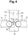
figure 4 représente une vue de profil des bandes transporteuses et de la bande convoyeuse illustrées sur lafigure 3 .
- There
Figure 1 represents a schematic plan view of an installation according to the invention. - There
Figure 2 represents a sectional view along line II-II of theFigure 1 . - There
Figure 3 represents a plan view of the aggregate transport system to the top of the mixing towers. - There
Figure 4 represents a side view of the conveyor belts and the conveyor belt illustrated in theFigure 3 .
Il faut noter que ces figures sont schématiques et ne sont pas prévues à la même échelle. Les éléments identiques ou analogues sont désignés sur les différentes figures par les mêmes références.It should be noted that these figures are schematic and are not intended to be drawn to the same scale. Identical or similar elements are designated in the different figures by the same references.
Ainsi qu'il ressort de la
Dans l'exemple illustré, on trouve de l'autre côté de la plate-forme deux rangées de chacune cinq trémies de stockage 5 et respectivement 5' qui sont chacune alignées au-dessus d'une bande transporteuse 6 et respectivement 6'. Ainsi qu'il ressort en particulier de la
Chaque trémie de stockage comprend, dans l'exemple illustré, une partie supérieure, qui, dans l'exemple illustré, comporte deux parois opposées verticales 11, 12, et respectivement 11', 12', qui sont disposées perpendiculairement à leur bande transporteuse 6, 6', et deux parois inclinées l'une vers l'autre 13, 14 et respectivement 13',14'. Cette partie supérieure débouche dans deux compartiments séparés 15, 16 et respectivement 15', 16' qui ont chacun la forme d'une pyramide renversée et qui présentent chacun un orifice de déversement 17 et respectivement 17', qui est obturable. Dans la trémie illustrée sur la
Dans l'exemple illustré, les bandes transporteuses 6 et 6' sont agencées de manière à défiler horizontalement l'une vers l'autre suivant une même direction horizontale, mais dans des sens opposés F1, F2, vers une extrémité basse 21 de la bande convoyeuse 20. Dans l'exemple illustré, les deux bandes transporteuses 6 et 6' déversent simultanément des agrégats par-dessus l'extrémité basse de la bande convoyeuse 20. Les agrégats, arrivant à une certaine vitesse, sont stoppés dans leur course par une tôle d'impact 30 qui pivote librement. Sur la
Celle-ci défile en oblique, dans le sens de la flèche F5, depuis son extrémité basse 21 jusqu'à une extrémité haute 22 située au-dessus des ouvertures supérieures d'entrée 23 et respectivement 23' des tours de malaxage 24 et respectivement 24'. Là, à l'aide d'un système d'aiguillage composé d'une tôle directrice 29 inclinée et orientable à l'aide d'un pivot vers l'une ou l'autre tour de malaxage 24, 24', la bande convoyeuse 20 déverse la matière granulaire qu'elle transporte dans un réservoir à agrégats 31, 31' représenté de manière schématique sur la
Chaque malaxeur est muni de manière connue de divers moyens d'alimentation, tels que des bascules, pour du liant hydraulique 25, 25', de l'eau 26, 26' et d'éventuels adjuvants 27, 27', tels que des plastifiants. Ces malaxeurs sont bien entendu aussi pourvus d'une ouverture inférieure de sortie obturable pour décharger une masse pâteuse de béton par exemple dans des camions toupies amenés sous les malaxeurs.Each mixer is provided in a known manner with various feeding means, such as scales, for
La mise en service de l'une ou l'autre des bandes transporteuses 6 et 6', de la bande convoyeuse 20, de l'un ou l'autre des malaxeurs des tours de malaxage 24, 24' ou des deux peut avantageusement être commandée ou contrôlée à distance à partir d'une seule unité de commande 19. Celle-ci peut avantageusement commander aussi l'ouverture ou la fermeture de chaque compartiment des trémies 5, 5', du réservoir à agrégats 31, 31', des bascules d'alimentation des malaxeurs et le pivotement du collecteur 29.The operation of one or other of the
Une série d'alimentations différentes de la bande convoyeuse 20 de l'installation illustrée va être décrite ci-dessous.
- Cas n°1 :
production de 2 gâchées identiques consécutives exploitant exclusivement des agrégats disponibles dans des trémies d'une seule série de trémies. - Granulats extraits : sable de Buir 0/4 (consigne à 3268 kg), calcaire concassé 2/6,3 (consigne à 993 kg), calcaire concassé 8/20 (consigne à 2773 kg).
- Séquence :
- A partir du côté trémies 5 : extraction du 0/4, puis du 2/6.3, puis du 8/20, démarrage de la bande convoyeuse
oblique 20, puis démarrage de la bande transporteuse horizontale 6, arrêt de la bande horizontale, démarrage des extractions suivantes,... et ainsi de suite. - Côté trémies 5' : aucune activité.
- A partir du côté trémies 5 : extraction du 0/4, puis du 2/6.3, puis du 8/20, démarrage de la bande convoyeuse
- Cas n°2 : production d'1 gâchée unique exploitant exclusivement des agrégats disponibles du côté trémies 5.
- Granulats extraits : sable de Buir 0/4 (consigne à 2738 kg), calcaire concassé 2/6.3 (consigne à 853 kg), calcaire concassé 8/20 (consigne à 2272 kg).
- Séquence :
- A partir du côté trémies 5 : extraction du 0/4, puis du 2/6.3, puis du 8/20, démarrage de la bande convoyeuse oblique, puis démarrage de la bande transporteuse horizontale, arrêt de la bande horizontale, arrêt de la bande oblique.
- Côté des trémies 5' : aucune activité.
- Cas n°3 : production d'1 gâchée (malaxeur 24) exploitant des agrégats disponibles des deux côtés (trémies 5 et trémies 5'), suivie d'1 gâchée (malaxeur 24') exploitant des agrégats disponibles des deux côtés.
- Granulats extraits :
- Gâchée 1 : calcaire concassé 2/6.3 (consigne à 2354 kg), calcaire concassé 6/20 (consigne à 4547 kg)
- Gâchée 2: sable de Buir 0/4 (consigne à 2914kg), calcaire concassé 2/6.3 (consigne à 880 kg), calcaire concassé 8/14 (consigne à 2426 kg)
- Séquence :
- Gâchée 1 : extraction du 2/6.3 du côté trémies 5 simultanément à l'extraction du 6/20 du côté trémies 5', démarrage de la bande convoyeuse oblique, puis démarrage simultané des deux bandes transporteuses horizontales, arrêt des bandes horizontales, arrêt de la bande oblique.
- Gâchée 2 : extraction du 0/4 du côté trémies 5 simultanément à l'extraction du 8/14 du côté trémies 5', puis extraction du 2/6.3 du côté trémies 5, démarrage de la bande oblique, puis démarrage simultané des deux bandes horizontales, arrêt des bandes horizontales, arrêt de la bande oblique.
- Cas n°4 : production d'1 gâchée (malaxeur 24) exploitant des agrégats disponibles des deux côtés (trémies 5 et trémies 5'), suivie d'1 gâchée identique (malaxeur 24') exploitant des agrégats disponibles des deux côtés, suivie d'1 gâchée identique (malaxeur 24) exploitant les agrégats disponibles des deux côtés.
- Granulats extraits : sable de Buir 0/4 (consigne à 3288kg), calcaire concassé 2/6.3 (consigne à 993kg), calcaire concassé 8/14 (consigne à 2737 kg).
- Séquence :
- En parallèle : extraction du 2/6.3 du côté trémies 5 simultanément à l'extraction du 8/14 du côté trémies 5', puis extraction du 2/6.3 du côté trémies 5, démarrage de la bande oblique, puis démarrage simultané des deux bandes horizontales, arrêt des bandes horizontales, arrêt de la bande oblique.
Suivi d'une 2eet d'une 3e séquences identiques.
- Cas n°5 : production d'1 gâchée (malaxeur 24') exploitant exclusivement des agrégats disponibles du côté trémies 5, suivie d'1 gâchée identique (malaxeur 24') exploitant exclusivement des agrégats disponibles du côté trémies 5 suivie avec retard et en parallèle d'1 gâchée (malaxeur 24) exploitant exclusivement des agrégats disponibles du côté trémies 5'.
- Granulats extraits :
Gâchées 1 et 2 : sable de Buir 0/4 (consigne à 3268kg), calcaire concassé 2/6.3 (consigne à 993kg), calcaire concassé 8/20 (consigne à 2773 kg)- Gâchée 3 : sable calcaire 0/2 (consigne à 1545kg)
- Séquence 1 :
- Côté trémies 5 : extraction du 0/4, puis du 2/6.3, puis du 8/20, démarrage de la bande oblique, puis démarrage de la bande horizontale, arrêt des bandes horizontales, arrêt de la bande oblique.
- Côté trémies 5' : pas d'activité.
- Séquence 2 :
Idem séquence 1
- Séquence 3 (intervient en cours de séquence 2)
- Côté trémies 5': extraction du 0/2, attente de libération de la bande oblique.
- Case No. 1: production of 2 consecutive identical batches using exclusively aggregates available in hoppers of a single series of hoppers.
- Extracted aggregates: Buir sand 0/4 (deposit at 3268 kg), crushed
limestone 2/6.3 (deposit at 993 kg), crushedlimestone 8/20 (deposit at 2773 kg). - Sequence :
- From hopper side 5: extraction of 0/4, then 2/6.3, then 8/20, start of
oblique conveyor belt 20, then start ofhorizontal conveyor belt 6, stop of the horizontal belt, start of the following extractions,... and so on. - Hopper side 5': no activity.
- From hopper side 5: extraction of 0/4, then 2/6.3, then 8/20, start of
- Case No. 2: production of a single batch using exclusively aggregates available on the
hopper side 5. - Extracted aggregates: Buir sand 0/4 (delivery at 2738 kg), crushed
limestone 2/6.3 (delivery at 853 kg), crushedlimestone 8/20 (delivery at 2272 kg). - Sequence :
- From the hopper side 5: extraction of 0/4, then 2/6.3, then 8/20, start of the oblique conveyor belt, then start of horizontal conveyor belt, stop of horizontal belt, stop of oblique belt.
- Hopper side 5': no activity.
- Case No. 3: production of 1 batch (mixer 24) using aggregates available on both sides (
hoppers 5 and hoppers 5'), followed by 1 batch (mixer 24') using aggregates available on both sides. - Extracted aggregates:
- Batch 1: crushed
limestone 2/6.3 (deposit at 2354 kg), crushedlimestone 6/20 (deposit at 4547 kg) - Batch 2: Buir sand 0/4 (deposit at 2914 kg), crushed
limestone 2/6.3 (deposit at 880 kg), crushedlimestone 8/14 (deposit at 2426 kg)
- Batch 1: crushed
- Sequence :
- Batch 1: extraction of 2/6.3 from the
hopper 5 side simultaneously with the extraction of 6/20 from the hopper 5' side, start of the oblique conveyor belt, then simultaneous start of the two horizontal conveyor belts, stop of the horizontal belts, stop of the oblique belt. - Batch 2: extraction of 0/4 from the
hoppers 5 side simultaneously with the extraction of 8/14 from the hoppers 5' side, then extraction of 2/6.3 from thehoppers 5 side, start of the oblique belt, then simultaneous start of the two horizontal belts, stop of the horizontal belts, stop of the oblique belt.
- Batch 1: extraction of 2/6.3 from the
- Case No. 4: production of 1 batch (mixer 24) using aggregates available on both sides (
hoppers 5 and hoppers 5'), followed by 1 identical batch (mixer 24') using aggregates available on both sides sides, followed by 1 identical batch (mixer 24) using the aggregates available on both sides. - Extracted aggregates: Buir sand 0/4 (deposit at 3288 kg), crushed
limestone 2/6.3 (deposit at 993 kg), crushedlimestone 8/14 (deposit at 2737 kg). - Sequence :
- In parallel: extraction of the 2/6.3 from the
hoppers 5 side simultaneously with the extraction of the 8/14 from the hoppers 5' side, then extraction of the 2/6.3 from thehoppers 5 side, start of the oblique belt, then simultaneous start of the two horizontal belts, stop of the horizontal belts, stop of the oblique belt. - Followed by a 2nd and a 3rd identical sequence.
- In parallel: extraction of the 2/6.3 from the
- Case No. 5: production of 1 batch (mixer 24') using only aggregates available on the
hopper 5 side, followed by 1 identical batch (mixer 24') using only aggregates available on thehopper 5 side followed with a delay and in parallel by 1 batch (mixer 24) using only aggregates available on the hopper 5' side. - Extracted aggregates:
-
Batches 1 and 2: Buir sand 0/4 (deposit at 3268 kg), crushedlimestone 2/6.3 (deposit at 993 kg), crushedlimestone 8/20 (deposit at 2773 kg) - Batch 3: limestone sand 0/2 (setpoint at 1545kg)
-
- Sequence 1:
- Hopper side 5: extraction of 0/4, then 2/6.3, then 8/20, start of the oblique belt, then start of the horizontal belt, stop of the horizontal belts, stop of the oblique belt.
- Hopper side 5': no activity.
- Sequence 2:
- Same as
sequence 1
- Same as
- Sequence 3 (occurs during sequence 2)
- Hopper side 5': extraction of 0/2, waiting for release of the oblique belt.
Il doit être entendu que la présente invention n'est en aucune façon limitée à la description qui précède et que bien des modifications pourraient y être apportées sans sortir du cadre des revendications qui suivent.It should be understood that the present invention is in no way limited to the foregoing description and that many modifications could be made thereto without departing from the scope of the following claims.
Claims (10)
- Method for producing concrete, comprising- transferring quantities of granular materials having different particle sizes into separate storage hoppers,- pouring dosed quantities of at least one of said granular materials from at least one of said hoppers of a first set of storage hoppers onto a first transport belt which, as a means of transport, runs along a direction, in a first direction,- pouring dosed quantities of at least one of said granular materials from at least one of said hoppers of a second set of storage hoppers onto a second transport belt which, as a means of transport, runs along said direction, in a second direction opposite to the first, and- transporting these dosed quantities of granular materials by means of said transport belts to a conveyor belt which conveys them to the top of two separate mixing towers, in each of which these granular materials are mixed with hydraulic binder, water and possibly adjuvants, to form a pasty mass of concrete, to be discharged for use thereof,- said transporting step comprising, in a selectable manner, supplying the conveyor belt with granular materials by means of the first transport belt or supplying the conveyor belt by means of the second transport belt,said transporting step further comprising, in a selectable manner, supplying the conveyor belt simultaneously by means of the first transport belt and by means of the second transport belt, the method being characterised by the use of an impact plate (30) arranged between the two discharge ends of the two transport belts (6, 6') to be freely pivotable about an axis perpendicular to the running direction of the transport belts, and in that said dosed quantities of granular materials are conveyed to the top of each of the mixing towers by the conveyor belt in a selectable manner through pivoting of an inclined guide plate (29), which directs the dosed quantities of materials into an aggregate tank of one mixing tower or into an aggregate tank of the other mixing tower.
- Method according to Claim 1, characterised in that the aforementioned granular materials comprise sand, grit and gravel of predetermined particle sizes.
- Method according to one of Claims 1 and 2, characterised in that said transferring step comprises pouring at least one of the granular materials into at least one storage hopper from a carrier vehicle.
- Method according to one of Claims 1 and 2, characterised in that said transferring step comprises preliminary storage of one of said granular materials in front of each storage hopper, so as to be able to be loaded thereinto by simple pushing.
- Method according to Claim 4, characterised in that it comprises primary storage of said granular materials, at a distance from said storage hoppers, and in that primary storage and intermediate storage take place at the same level.
- Method according to one of Claims 1 to 5, characterised in that it comprises weighing the granular materials poured onto each transport belt.
- Concrete production facility, comprising- storage hoppers (5, 5') for receiving granular materials having different particle sizes, which are provided with an upper loading opening (7, 7') and a lower discharge opening (17, 17'),- a first set of storage hoppers (5) which is aligned above a first transport belt (6), as a means of transport that runs to a bottom end (21) of a conveyor belt (20) along a direction, in a first direction,- a second set of storage hoppers (5') which is aligned above a second transport belt (6'), as a means of transport that runs to the bottom end (21) of said conveyor belt (20) along said direction, in a second direction opposite to the first,- the two transport belts each having a discharge end arranged above said bottom end of the conveyor belt, and- a mixing stage, comprising at least two mixing towers (24, 24') each having an upper inlet opening, each of these mixing towers being provided with means for supplying hydraulic binder (25), water (26) and optional adjuvants (27), a mixing device and a sealable lower outlet opening for discharging a pasty mass of concrete,- the conveyor belt (20) running slantwise from said bottom end (21) to a top end (22) located above the upper inlet openings of the mixing towers (24, 24'),- control means (19) which are arranged to open or close the discharge opening (17, 17') of one or more hoppers (5, 5') of one or both sets of storage hoppers and to set in motion one of the transport belts (6, 6') or both of them simultaneously so as to allow the granular materials to be simultaneously delivered to the conveyor belt (20) from the first and second transport belts (6, 6') or to stop this delivery from one of the two transport belts,characterised in that an impact plate (30) is arranged between the two discharge ends of the two transport belts (6, 6') so as to be able to pivot freely about an axis perpendicular to the running direction of the transport belts, in that the top end (22) of the conveyor belt opens onto an inclined, pivoting guide plate (29), which directs the dosed quantities of granular materials into an aggregate tank (31) of one of the mixing towers or into an aggregate tank (31') of the other of said mixing towers, and in that the control means (19) are arranged to control a pivoting of the pivoting guide plate (29) so as to direct the granular materials into the aggregate tank (31, 31') of either of the mixing towers (24, 24').
- Facility according to Claim 7, characterised in that it comprises an intermediate storage area (8, 8') in front of the upper loading opening of each of the storage hoppers (5, 5').
- Facility according to Claim 8, characterised in that it further comprises primary storage areas (3) for storing the granular materials, located at a distance from the storage hoppers (5, 5'), and in that the primary storage areas and the intermediate storage areas (8, 8') are arranged at the same level which is equal to or higher than the upper inlet openings (7, 7') of the storage hoppers.
- Facility according to one of Claims 7 to 9, characterised in that at least one storage hopper comprises an upper part opening into a lower part comprising at least two separate compartments (15, 16; 15', 16') each provided with a lower discharge opening (17, 17'), which can be sealed independently of the discharge opening of the other compartment.
Applications Claiming Priority (1)
| Application Number | Priority Date | Filing Date | Title |
|---|---|---|---|
| BE20216018A BE1030054B1 (en) | 2021-12-21 | 2021-12-21 | CONCRETE MANUFACTURING PROCESS AND FACILITY |
Publications (2)
| Publication Number | Publication Date |
|---|---|
| EP4201625A1 EP4201625A1 (en) | 2023-06-28 |
| EP4201625B1 true EP4201625B1 (en) | 2025-04-09 |
Family
ID=79425554
Family Applications (1)
| Application Number | Title | Priority Date | Filing Date |
|---|---|---|---|
| EP22215150.8A Active EP4201625B1 (en) | 2021-12-21 | 2022-12-20 | Method and plant for producing concrete |
Country Status (2)
| Country | Link |
|---|---|
| EP (1) | EP4201625B1 (en) |
| BE (1) | BE1030054B1 (en) |
Family Cites Families (3)
| Publication number | Priority date | Publication date | Assignee | Title |
|---|---|---|---|---|
| FR2953423B1 (en) * | 2009-12-09 | 2013-10-18 | Actial | COLD MIXING ASSEMBLY CAPABLE OF PRODUCING DIFFERENT PRODUCTS, AND METHOD FOR IMPLEMENTING THE SAME |
| CN105908600B (en) * | 2016-04-13 | 2020-04-14 | 贵州路桥集团有限公司 | Method for mounting underlying proportioning bin of mixer |
| CN110394899A (en) * | 2019-08-13 | 2019-11-01 | 杭州江河机电装备工程有限公司 | Aggregate feeding system and control method of a mixing station |
-
2021
- 2021-12-21 BE BE20216018A patent/BE1030054B1/en active IP Right Grant
-
2022
- 2022-12-20 EP EP22215150.8A patent/EP4201625B1/en active Active
Also Published As
| Publication number | Publication date |
|---|---|
| BE1030054B1 (en) | 2023-07-18 |
| EP4201625A1 (en) | 2023-06-28 |
| BE1030054A1 (en) | 2023-07-13 |
Similar Documents
| Publication | Publication Date | Title |
|---|---|---|
| CA3043303C (en) | A concrete batching plant having reduced cycle time and reduced installation and dismantling time | |
| FR2550248A1 (en) | MOBILE DEVICE FOR COLD WINDING AND ROAD SPREADING OF BITUMINOUS COATED PRODUCTS FOR ROAD COVERINGS | |
| EP4201625B1 (en) | Method and plant for producing concrete | |
| EP1324865B1 (en) | Method for producing in a continuous installation a compacted rolled concrete composition reinforced with metal fibres, and continuous installation therefor | |
| FR2599771A1 (en) | Machine for hydraulic shotcreting | |
| CN109333829A (en) | The totally-enclosed automatic feeding system of ready-mixed concrete and operating method | |
| EP1910620B1 (en) | Plant and method for treating loamy debris | |
| FR2642056A1 (en) | DEVICE FOR FEEDING A PLURALITY OF GRANULAR PRODUCTS STORAGE HOPPERS | |
| EP1317969B1 (en) | Method and device for treating mineral materials such as soil or recycled material | |
| BE1006618A3 (en) | DEVICE FOR FOOD OF VIS extractor LIFT OR IN BULK MATERIAL. | |
| US20050161107A1 (en) | Apparatus and method for loading concrete components in a mixing truck | |
| CA2570854A1 (en) | Mobile device for the granulation of dairy fines | |
| CN211812383U (en) | Grit feeding system for grit storage silo | |
| FR2813619A1 (en) | Procedure and machine for making cold bitumen-bound materials for road surfacing uses initial phase with water added to mixed components | |
| RU2039272C1 (en) | Method for dumping and working of hard rocks with coarse fractionation | |
| WO2025262101A1 (en) | Method for recycling and recovering concrete sludge | |
| WO2023144478A1 (en) | Self-service concrete plant | |
| JPH1136268A (en) | Conveying method and conveying device for dam concrete | |
| FR2854643A1 (en) | Road lining material e.g. granule, fabricating installation for roadwork, has mixer mixing granules, hydraulic and bituminous binders, and conveyor extending between granule hopper and mixer and arranged parallel to storing bin | |
| EP1775091A1 (en) | Apparatus for processing an aggregate mix and cement | |
| FR2862669A1 (en) | Device for supplying recycled bituminous granules to installation which fabricates bituminous products in Batchs, where integrated assembly measures and weighs granules into mixture | |
| KR101159667B1 (en) | Heaping apparatus for fuel or raw materials | |
| FR3165203A1 (en) | Device and method for supplying solid materials with a mixture of plant-based granules for projection, and projection machine including the device | |
| FR3016823A1 (en) | CENTRAL MANUFACTURING OF CONSTRUCTION MATERIAL | |
| BE1032172A1 (en) | Vibrating device for forming concrete specimens |
Legal Events
| Date | Code | Title | Description |
|---|---|---|---|
| PUAI | Public reference made under article 153(3) epc to a published international application that has entered the european phase |
Free format text: ORIGINAL CODE: 0009012 |
|
| STAA | Information on the status of an ep patent application or granted ep patent |
Free format text: STATUS: THE APPLICATION HAS BEEN PUBLISHED |
|
| AK | Designated contracting states |
Kind code of ref document: A1 Designated state(s): AL AT BE BG CH CY CZ DE DK EE ES FI FR GB GR HR HU IE IS IT LI LT LU LV MC ME MK MT NL NO PL PT RO RS SE SI SK SM TR |
|
| STAA | Information on the status of an ep patent application or granted ep patent |
Free format text: STATUS: REQUEST FOR EXAMINATION WAS MADE |
|
| 17P | Request for examination filed |
Effective date: 20231130 |
|
| RBV | Designated contracting states (corrected) |
Designated state(s): AL AT BE BG CH CY CZ DE DK EE ES FI FR GB GR HR HU IE IS IT LI LT LU LV MC ME MK MT NL NO PL PT RO RS SE SI SK SM TR |
|
| GRAP | Despatch of communication of intention to grant a patent |
Free format text: ORIGINAL CODE: EPIDOSNIGR1 |
|
| STAA | Information on the status of an ep patent application or granted ep patent |
Free format text: STATUS: GRANT OF PATENT IS INTENDED |
|
| INTG | Intention to grant announced |
Effective date: 20241217 |
|
| GRAS | Grant fee paid |
Free format text: ORIGINAL CODE: EPIDOSNIGR3 |
|
| GRAA | (expected) grant |
Free format text: ORIGINAL CODE: 0009210 |
|
| STAA | Information on the status of an ep patent application or granted ep patent |
Free format text: STATUS: THE PATENT HAS BEEN GRANTED |
|
| AK | Designated contracting states |
Kind code of ref document: B1 Designated state(s): AL AT BE BG CH CY CZ DE DK EE ES FI FR GB GR HR HU IE IS IT LI LT LU LV MC ME MK MT NL NO PL PT RO RS SE SI SK SM TR |
|
| REG | Reference to a national code |
Ref country code: GB Ref legal event code: FG4D Free format text: NOT ENGLISH |
|
| REG | Reference to a national code |
Ref country code: CH Ref legal event code: EP |
|
| REG | Reference to a national code |
Ref country code: DE Ref legal event code: R096 Ref document number: 602022012870 Country of ref document: DE |
|
| REG | Reference to a national code |
Ref country code: IE Ref legal event code: FG4D Free format text: LANGUAGE OF EP DOCUMENT: FRENCH |
|
| REG | Reference to a national code |
Ref country code: NL Ref legal event code: MP Effective date: 20250409 |
|
| PG25 | Lapsed in a contracting state [announced via postgrant information from national office to epo] |
Ref country code: NL Free format text: LAPSE BECAUSE OF FAILURE TO SUBMIT A TRANSLATION OF THE DESCRIPTION OR TO PAY THE FEE WITHIN THE PRESCRIBED TIME-LIMIT Effective date: 20250409 |
|
| REG | Reference to a national code |
Ref country code: AT Ref legal event code: MK05 Ref document number: 1783169 Country of ref document: AT Kind code of ref document: T Effective date: 20250409 |
|
| PG25 | Lapsed in a contracting state [announced via postgrant information from national office to epo] |
Ref country code: FI Free format text: LAPSE BECAUSE OF FAILURE TO SUBMIT A TRANSLATION OF THE DESCRIPTION OR TO PAY THE FEE WITHIN THE PRESCRIBED TIME-LIMIT Effective date: 20250409 Ref country code: PT Free format text: LAPSE BECAUSE OF FAILURE TO SUBMIT A TRANSLATION OF THE DESCRIPTION OR TO PAY THE FEE WITHIN THE PRESCRIBED TIME-LIMIT Effective date: 20250811 Ref country code: ES Free format text: LAPSE BECAUSE OF FAILURE TO SUBMIT A TRANSLATION OF THE DESCRIPTION OR TO PAY THE FEE WITHIN THE PRESCRIBED TIME-LIMIT Effective date: 20250409 |
|
| REG | Reference to a national code |
Ref country code: LT Ref legal event code: MG9D |
|
| PG25 | Lapsed in a contracting state [announced via postgrant information from national office to epo] |
Ref country code: NO Free format text: LAPSE BECAUSE OF FAILURE TO SUBMIT A TRANSLATION OF THE DESCRIPTION OR TO PAY THE FEE WITHIN THE PRESCRIBED TIME-LIMIT Effective date: 20250709 Ref country code: GR Free format text: LAPSE BECAUSE OF FAILURE TO SUBMIT A TRANSLATION OF THE DESCRIPTION OR TO PAY THE FEE WITHIN THE PRESCRIBED TIME-LIMIT Effective date: 20250710 |
|
| PG25 | Lapsed in a contracting state [announced via postgrant information from national office to epo] |
Ref country code: PL Free format text: LAPSE BECAUSE OF FAILURE TO SUBMIT A TRANSLATION OF THE DESCRIPTION OR TO PAY THE FEE WITHIN THE PRESCRIBED TIME-LIMIT Effective date: 20250409 |
|
| PG25 | Lapsed in a contracting state [announced via postgrant information from national office to epo] |
Ref country code: BG Free format text: LAPSE BECAUSE OF FAILURE TO SUBMIT A TRANSLATION OF THE DESCRIPTION OR TO PAY THE FEE WITHIN THE PRESCRIBED TIME-LIMIT Effective date: 20250409 |
|
| PG25 | Lapsed in a contracting state [announced via postgrant information from national office to epo] |
Ref country code: HR Free format text: LAPSE BECAUSE OF FAILURE TO SUBMIT A TRANSLATION OF THE DESCRIPTION OR TO PAY THE FEE WITHIN THE PRESCRIBED TIME-LIMIT Effective date: 20250409 |
|
| PG25 | Lapsed in a contracting state [announced via postgrant information from national office to epo] |
Ref country code: AT Free format text: LAPSE BECAUSE OF FAILURE TO SUBMIT A TRANSLATION OF THE DESCRIPTION OR TO PAY THE FEE WITHIN THE PRESCRIBED TIME-LIMIT Effective date: 20250409 |
|
| PG25 | Lapsed in a contracting state [announced via postgrant information from national office to epo] |
Ref country code: RS Free format text: LAPSE BECAUSE OF FAILURE TO SUBMIT A TRANSLATION OF THE DESCRIPTION OR TO PAY THE FEE WITHIN THE PRESCRIBED TIME-LIMIT Effective date: 20250709 |
|
| PG25 | Lapsed in a contracting state [announced via postgrant information from national office to epo] |
Ref country code: IS Free format text: LAPSE BECAUSE OF FAILURE TO SUBMIT A TRANSLATION OF THE DESCRIPTION OR TO PAY THE FEE WITHIN THE PRESCRIBED TIME-LIMIT Effective date: 20250809 |
|
| PG25 | Lapsed in a contracting state [announced via postgrant information from national office to epo] |
Ref country code: LV Free format text: LAPSE BECAUSE OF FAILURE TO SUBMIT A TRANSLATION OF THE DESCRIPTION OR TO PAY THE FEE WITHIN THE PRESCRIBED TIME-LIMIT Effective date: 20250409 |
|
| PG25 | Lapsed in a contracting state [announced via postgrant information from national office to epo] |
Ref country code: SM Free format text: LAPSE BECAUSE OF FAILURE TO SUBMIT A TRANSLATION OF THE DESCRIPTION OR TO PAY THE FEE WITHIN THE PRESCRIBED TIME-LIMIT Effective date: 20250409 Ref country code: DK Free format text: LAPSE BECAUSE OF FAILURE TO SUBMIT A TRANSLATION OF THE DESCRIPTION OR TO PAY THE FEE WITHIN THE PRESCRIBED TIME-LIMIT Effective date: 20250409 |
|
| PGFP | Annual fee paid to national office [announced via postgrant information from national office to epo] |
Ref country code: BE Payment date: 20251216 Year of fee payment: 4 |
|
| PG25 | Lapsed in a contracting state [announced via postgrant information from national office to epo] |
Ref country code: CZ Free format text: LAPSE BECAUSE OF FAILURE TO SUBMIT A TRANSLATION OF THE DESCRIPTION OR TO PAY THE FEE WITHIN THE PRESCRIBED TIME-LIMIT Effective date: 20250409 |
|
| PG25 | Lapsed in a contracting state [announced via postgrant information from national office to epo] |
Ref country code: EE Free format text: LAPSE BECAUSE OF FAILURE TO SUBMIT A TRANSLATION OF THE DESCRIPTION OR TO PAY THE FEE WITHIN THE PRESCRIBED TIME-LIMIT Effective date: 20250409 |
|
| PG25 | Lapsed in a contracting state [announced via postgrant information from national office to epo] |
Ref country code: SK Free format text: LAPSE BECAUSE OF FAILURE TO SUBMIT A TRANSLATION OF THE DESCRIPTION OR TO PAY THE FEE WITHIN THE PRESCRIBED TIME-LIMIT Effective date: 20250409 |
|
| PG25 | Lapsed in a contracting state [announced via postgrant information from national office to epo] |
Ref country code: IT Free format text: LAPSE BECAUSE OF FAILURE TO SUBMIT A TRANSLATION OF THE DESCRIPTION OR TO PAY THE FEE WITHIN THE PRESCRIBED TIME-LIMIT Effective date: 20250409 |
|
| PLBE | No opposition filed within time limit |
Free format text: ORIGINAL CODE: 0009261 |
|
| STAA | Information on the status of an ep patent application or granted ep patent |
Free format text: STATUS: NO OPPOSITION FILED WITHIN TIME LIMIT |