EP4201625B1 - Verfahren und anlage zur herstellung von beton - Google Patents
Verfahren und anlage zur herstellung von beton Download PDFInfo
- Publication number
- EP4201625B1 EP4201625B1 EP22215150.8A EP22215150A EP4201625B1 EP 4201625 B1 EP4201625 B1 EP 4201625B1 EP 22215150 A EP22215150 A EP 22215150A EP 4201625 B1 EP4201625 B1 EP 4201625B1
- Authority
- EP
- European Patent Office
- Prior art keywords
- granular materials
- storage
- transport
- conveyor belt
- hoppers
- Prior art date
- Legal status (The legal status is an assumption and is not a legal conclusion. Google has not performed a legal analysis and makes no representation as to the accuracy of the status listed.)
- Active
Links
Images


Classifications
-
- B—PERFORMING OPERATIONS; TRANSPORTING
- B28—WORKING CEMENT, CLAY, OR STONE
- B28C—PREPARING CLAY; PRODUCING MIXTURES CONTAINING CLAY OR CEMENTITIOUS MATERIAL, e.g. PLASTER
- B28C7/00—Controlling the operation of apparatus for producing mixtures of clay or cement with other substances; Supplying or proportioning the ingredients for mixing clay or cement with other substances; Discharging the mixture
- B28C7/04—Supplying or proportioning the ingredients
- B28C7/0481—Plant for proportioning, supplying or batching
-
- B—PERFORMING OPERATIONS; TRANSPORTING
- B28—WORKING CEMENT, CLAY, OR STONE
- B28C—PREPARING CLAY; PRODUCING MIXTURES CONTAINING CLAY OR CEMENTITIOUS MATERIAL, e.g. PLASTER
- B28C7/00—Controlling the operation of apparatus for producing mixtures of clay or cement with other substances; Supplying or proportioning the ingredients for mixing clay or cement with other substances; Discharging the mixture
- B28C7/0046—Storage or weighing apparatus for supplying ingredients
- B28C7/0053—Storage containers, e.g. hoppers, silos, bins
- B28C7/0061—Storage container plant
-
- B—PERFORMING OPERATIONS; TRANSPORTING
- B28—WORKING CEMENT, CLAY, OR STONE
- B28C—PREPARING CLAY; PRODUCING MIXTURES CONTAINING CLAY OR CEMENTITIOUS MATERIAL, e.g. PLASTER
- B28C7/00—Controlling the operation of apparatus for producing mixtures of clay or cement with other substances; Supplying or proportioning the ingredients for mixing clay or cement with other substances; Discharging the mixture
- B28C7/0046—Storage or weighing apparatus for supplying ingredients
- B28C7/0053—Storage containers, e.g. hoppers, silos, bins
- B28C7/0069—Storage containers, e.g. hoppers, silos, bins having compartments
-
- B—PERFORMING OPERATIONS; TRANSPORTING
- B28—WORKING CEMENT, CLAY, OR STONE
- B28C—PREPARING CLAY; PRODUCING MIXTURES CONTAINING CLAY OR CEMENTITIOUS MATERIAL, e.g. PLASTER
- B28C7/00—Controlling the operation of apparatus for producing mixtures of clay or cement with other substances; Supplying or proportioning the ingredients for mixing clay or cement with other substances; Discharging the mixture
- B28C7/04—Supplying or proportioning the ingredients
- B28C7/06—Supplying the solid ingredients, e.g. by means of endless conveyors or jigging conveyors
- B28C7/067—Supplying the solid ingredients, e.g. by means of endless conveyors or jigging conveyors by means of stationary hoppers, chambers or bins from which the material is fed gravitationally, e.g. having agitating means therein
Definitions
- the present invention relates to a method and an installation for manufacturing concrete.
- Concrete manufacturing methods comprising transferring quantities of granular materials having different particle sizes into separate storage hoppers, discharging metered quantities of at least one of said granular materials from at least one of said storage hoppers onto a conveying means, transporting these metered quantities by said conveying means to a conveyor belt which conveys them to the top of a mixing stage, mixing, in this mixing stage, said metered quantities, conveyed, of at least one of said granular materials with hydraulic binder, water and possible additives, to form a pasty mass of concrete, and discharging said pasty mass of concrete from the mixing stage, for its exploitation.
- an installation in a known manner which comprises storage hoppers for receiving granular materials having different particle sizes, which are provided with an upper loading opening and a lower, closable discharge orifice, a transport means onto which metered quantities of granular materials are discharged from said storage hoppers, a conveyor belt onto which said transport means brings said metered quantities of granular materials, and a mixing stage having an inlet, where said conveyor belt carries said metered quantities of granular materials, means for supplying hydraulic binder, water and possible additives and a closable outlet for discharging a pasty mass of concrete.
- mixing stage is meant all the elements and devices which allow mixing of material, and therefore not only the mixer, but also the mixer feed systems.
- this mixing stage has the form of a tower, the upper level of which comprises scales for water, cement and any additives, as well as an aggregate tank for receiving the already dosed quantities of granular materials and the lower level of which consists of the mixer itself.
- the scales and the aggregate tank can empty simultaneously into the mixer.
- Concrete manufacturing facilities are used to supply products of several types, such as Bénor concretes that comply with European standards or rich concretes known as "on composition", lean concretes, or various mixtures based on cement and aggregates such as stabilized stone, stabilized sand, screeds, specific concretes (road, cavernous, colloidal, etc.). Special admixtures are sometimes required and there is an increasing demand for recycling certain previously used materials into concrete.
- Concrete is mixed in a mixing tank called a batching tank, and production is therefore carried out in batches which are obtained every 20 to 50 seconds, then poured into mixing vehicles, for example concrete mixer trucks, each concrete mixer truck being able to contain for example 3 batches. This pouring can also take place in dump trucks, flatbed trucks or even simple trailers attached to cars.
- mixing vehicles for example concrete mixer trucks, each concrete mixer truck being able to contain for example 3 batches. This pouring can also take place in dump trucks, flatbed trucks or even simple trailers attached to cars.
- a method for manufacturing concrete comprising transferring quantities of granular materials having different particle sizes into separate storage hoppers, discharging metered quantities of at least one of said granular materials from at least one of said hoppers of a first series of storage hoppers onto a first conveyor belt which, as a means of transport, runs in one direction, in a first direction, discharging metered quantities of at least one of said granular materials from at least one of said hoppers of a second series of storage hoppers onto a second conveyor belt which, as a means of transport, runs in said direction, in a second direction opposite to the first, and transporting these metered quantities of granular materials by said conveyor belts to a conveyor belt which conveys them to the top of two separate mixing towers, in each of which these granular materials are mixed with binder hydraulic, water and possible adjuvants, to form a pasty mass of concrete, to be discharged for its exploitation, said transport step comprising selectably a
- the present invention aims to solve these problems and to propose a method and a concrete manufacturing installation which make it possible to improve the performance of concrete production installations and which allow great flexibility in the manufacturing of different concretes in the same installation.
- the aforementioned granular materials also called aggregates, which include sands, gravels, and gravels of predetermined granulometric sizes, can be brought to the mixers in successive mixtures that are easily adaptable.
- the conveyor belt can be fed by one or more conveyor belts, each supplied from one or more storage hoppers, which substantially multiplies the number of different granular mixtures that can be conveyed to the aggregate tank of one of the mixing towers or the other.
- the quantity of hydraulic binder, water or admixture can be adjusted independently according to demand. Two concrete trucks can therefore collect two concretes of different qualities from the bottom of the mixers almost simultaneously.
- said transfer step comprises pouring at least one of the granular materials into at least one storage hopper from a carrier vehicle.
- a carrier vehicle it is advantageous to envisage, for example, dump trucks.
- said transfer step comprises an intermediate storage of one of said granular materials opposite each storage hopper, and a loading thereof by simple pushing of the granular material.
- the method according to the invention comprises a primary storage of said granular materials, separately, at a distance from said storage hoppers, and at the same level as the intermediate storage and said transfer step comprises a step of preliminary movement of the granular material from the primary storage directly to the hoppers or to the intermediate storage, prior to loading the hoppers.
- the method comprises weighing the granular materials discharged onto the conveyor belts. Weighing each conveyor belt during each aforementioned discharge onto it of one of said granular materials allows metering of the quantities discharged from the storage hoppers.
- an impact plate is arranged between the two discharge ends of the two conveyor belts so as to be able to pivot freely about an axis perpendicular to the direction of travel of the conveyor belts, the upper end of the conveyor belt opening onto an inclined, pivoting guide plate, which directs the metered quantities of granular materials into an aggregate tank of one of the mixing towers or into an aggregate tank of the other of said mixing towers, the installation further comprising control means which are arranged to produce an opening or a closing of the discharge orifice of one or more hoppers of one or both series of storage hoppers and a setting in motion of one of the conveyor belts or both simultaneously so as to allow a simultaneous supply of the granular materials to the conveyor belt from the first and second conveyor belts or a stopping of this supply from one of the two conveyor belts and to control a pivoting the pivoting guide plate so as to direct the granular materials into the aggregate tank of one or other of the mixing towers.
- control means are integrated into a remote control unit.
- the moving conveyor belts are therefore arranged so as to move towards a lower end of the conveyor belt. They are, in a selected manner, loaded or not with one or more granular materials.
- the impact plate can pivot freely under the thrust of the aggregate flows discharged from the left and/or right by the conveyor belts. In this way it directs in at any time and in a quasi-vertical manner this or these flows towards the lower end of the conveyor belt.
- this impact plate pivots to the opposite side under their thrust which has the effect of preventing the granular materials from overflowing beyond the conveyor belt.
- the impact plate When granular materials are discharged from both conveyor belts simultaneously, the impact plate remains static in a vertical position and it has the additional effect of channeling the flows and thus preventing them from interacting with each other in an undesirable manner.
- the conveyor belt runs obliquely from this lower end to a high end located above the upper inlet openings of the mixing towers, and the high end of the conveyor belt opens onto an inclined, pivoting guide plate, which directs the metered quantities of granular materials directly into the aggregate tank of one or other of the said mixing towers.
- the installation comprises an intermediate storage area in front of the upper loading opening of each of the storage hoppers.
- These intermediate storage areas can form a buffer storage space before storage in the hoppers. They can also be used to accommodate a carrier vehicle capable of directly pouring granular material into the corresponding hopper, when the latter is empty. Dump trucks can then pour their contents directly into the hopper, thus avoiding costly handling by a loader machine which still has to push the stored material.
- the installation further comprises primary storage areas for the granular materials, located at a distance from the hoppers storage, and the primary storage areas and the intermediate storage areas are arranged at the same level which is equal to or higher than the upper inlet openings of the storage hoppers.
- these primary storage and intermediate storage areas are arranged on a single platform on which, for example, several loading machines can circulate simultaneously and carry out a transfer of each of the granular materials to its intermediate storage area(s), as required.
- These same loading machines are also capable of pushing the granular materials from their intermediate storage area into their storage hopper.
- an access ramp for trucks, or any other common means of transport can be considered. This general arrangement allows loading of each hopper independently of the others as required and therefore a faster and easier supply of the installation.
- At least one storage hopper comprises an upper part opening onto a lower part comprising at least two separate compartments each provided with a lower discharge opening, closable independently of the discharge opening of the other compartment.
- This arrangement facilitates precisely regulated metering of the mixture of granular materials to be fed by the respective conveyor belt to the conveyor belt and allows an adjusted discharge speed.
- one or two of the lower discharge openings are opened.
- the openings of the aforementioned compartments can be closed by conventional means such as, for example, flaps for gravel and extractor belts for sand.
- the illustrated installation comprises a platform 1, to which dump trucks containing granular materials can reach via an access ramp 2.
- Several primary storage areas 3 are provided on one side of the platform, in housings separated by partitions 4.
- granular materials such as sand, gravel, gravel of various granulometric sizes, naturally at a rate of only one material per housing.
- These granular materials have granulometric sizes corresponding to common standards, for example 0/80, 0/63, 32/63, 63/150, 0/20, 0/6.3, 6.3/20 etc. which will then be used independently depending on the finished product to be produced.
- These standards correspond to the mesh openings of the screens and are to be expressed in mm.
- each five storage hoppers 5 and 5' respectively, each of which is aligned above a conveyor belt 6 and 6' respectively.
- these hoppers 5, 5' each have an upper loading opening 7 and respectively 7', which, in the example illustrated, is located at the level of the platform 1.
- Intermediate storage areas 8 and respectively 8' are arranged on the platform 1 in front of each storage hopper, being separated from each other by partitions 9 and respectively 9'. These intermediate storage areas 8, 8' serve as buffers between the primary storage areas 3 and the storage hoppers 5, 5'.
- Each storage hopper comprises, in the example illustrated, an upper part, which, in the example illustrated, comprises two vertical opposite walls 11, 12, and respectively 11', 12', which are arranged perpendicular to their conveyor belt 6, 6', and two walls inclined towards each other 13, 14 and respectively 13', 14'.
- This upper part opens into two separate compartments 15, 16 and respectively 15', 16' which each have the shape of an inverted pyramid and which each have a discharge orifice 17 and respectively 17', which is closable.
- the discharge opening is closed by a valve 18. This valve closes the corresponding compartment of the hopper if the latter is not to see the granular material it contains discharged or it opens it otherwise.
- valve 18 The passage of the valve 18 from an open position to a closed position or vice versa is carried out using any usual means known to those skilled in the art. In the example illustrated it is opened using two jacks 28 controlled remotely from a control unit 19.
- the hopper contains a fine granular material, such as sand, it may be advantageous to regulate its discharge, not by a valve, but by an extractor belt known per se for this purpose, which can also be set in motion by the control unit 19.
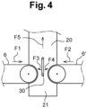
- the conveyor belts 6 and 6' are arranged so as to travel horizontally towards each other in the same horizontal direction, but in opposite directions F1, F2, towards a lower end 21 of the conveyor belt 20.
- the two conveyor belts 6 and 6' simultaneously discharge aggregates over the lower end of the conveyor belt 20.
- the aggregates, arriving at a certain speed, are stopped in their course by an impact plate 30 which pivots freely.
- the impact plate is in a vertical position, because it is subjected to the thrust of the material flows which come simultaneously from the conveyor belt 6 and the conveyor belt 6'.
- the pivoting impact plate As the pivoting impact plate is located between the two ends of the two conveyor belts 6, 6', it has the effect of causing an almost vertical fall of the aggregates from each of the conveyor belts towards the conveyor belt 20.
- the impact plate 30 can, under the thrust of the material, pivot along one of the arrows F3 or F4, in thus preventing aggregates from overflowing beyond the conveyor belt.
- Each mixer is provided in a known manner with various feeding means, such as scales, for hydraulic binder 25, 25', water 26, 26' and possible additives 27, 27', such as plasticizers.
- These mixers are of course also provided with a lower closable outlet opening for discharging a pasty mass of concrete, for example into mixer trucks brought under the mixers.
Landscapes
- Chemical & Material Sciences (AREA)
- Dispersion Chemistry (AREA)
- Preparation Of Clay, And Manufacture Of Mixtures Containing Clay Or Cement (AREA)
- Filling Or Emptying Of Bunkers, Hoppers, And Tanks (AREA)
Claims (10)
- Verfahren zur Herstellung von Beton, umfassend:- ein Umfüllen von Mengen von granularem Material, das unterschiedliche granulometrische Dimensionen enthält, in getrennte Lagerbehälter,- ein Ausschütten der dosierten Mengen mindestens eines granularen Materials aus mindestens einem der Behälter einer ersten Reihe von Lagerbehältern auf ein erstes Transportband, das, als Transportmittel, entlang einer Richtung, in einer ersten Laufrichtung verläuft,- ein Ausschütten der dosierten Mengen mindestens eines granularen Materials aus mindestens einem der Behälter einer zweiten Reihe von Lagerbehältern auf ein zweites Transportband, das, als Transportmittel, entlang der Richtung, in einer zweiten Laufrichtung verläuft, die entgegengesetzt zur ersten ist, und- ein Transportieren dieser dosierten Mengen von granularem Material durch die Transportbänder zu einem Förderband, das sie an die Spitze von zwei getrennten Mischtürmen befördert, in denen diese granularen Materialien jeweils mit hydraulischem Bindemittel, Wasser und eventuellen Zusatzstoffen vermischt werden, um eine pastöse Betonmasse zu bilden, die für ihre Verwendung abgelassen werden soll,- wobei der Transportschritt auf wählbare Weise eine Beschickung des Förderbands mit granularen Materialien durch das erste Transportband umfasst oder eine Beschickung des Förderbands durch das zweite Transportband,wobei der Transportschritt ferner auf wählbare Weise eine gleichzeitige Beschickung des Förderbands durch das erste Transportband und durch das zweite Transportband umfasst, wobei das Verfahren durch die Verwendung eines Prallblechs (30) gekennzeichnet ist, das zwischen den zwei Enden der Ausschüttung der zwei Transportbänder (6, 6') angeordnet ist, durch freies Schwenken um eine Achse senkrecht zur Laufrichtung der Transportbänder, und dadurch, dass das Befördern der dosierten Mengen von granularem Material zur Oberseite jedes einzelnen Mischturms durch das Förderband auf wählbare Weise durch Schwenken eines geneigten Leitblechs (29) erfolgt, das die dosierten Mengen an Material in einen Aggregatsilo des einen Mischturms oder in einen Aggregatsilo des anderen Mischturms leitet.
- Verfahren nach Anspruch 1, dadurch gekennzeichnet, dass die granularen Materialien Sand, Splitt und Kies mit vorbestimmten granulometrischen Dimensionen umfassen.
- Verfahren nach einem der Ansprüche 1 und 2, dadurch gekennzeichnet, dass der Umfüllschritt das Einfüllen von mindestens einem der Granulate aus einem Trägerfahrzeug in mindestens einen Lagerbehälter umfasst.
- Verfahren nach einem der Ansprüche 1 und 2, dadurch gekennzeichnet, dass der Umfüllschritt eine vorgängige Deponierung eines granularen Materials gegenüber jedem Lagerbehälter umfasst, so dass es durch einfaches Schieben in diesen geladen werden kann.
- Verfahren nach Anspruch 4, dadurch gekennzeichnet, dass es eine primäre Lagerung der granularen Materialien in einem Abstand von den Lagerbehältern umfasst, und dass die primäre Lagerung und die Zwischendeponierung auf derselben Ebene stattfinden.
- Verfahren nach einem der Ansprüche 1 bis 5, dadurch gekennzeichnet, dass es ein Wiegen des auf jedes Transportband geschütteten granularen Materials umfasst.
- Betonherstellungsanlage, umfassend:- Lagerbehälter (5, 5') zur Aufnahme von granularen Materialien, die unterschiedliche granulometrische Dimensionen enthält, und die mit einer oberen Beladeöffnung (7,7') und einer unteren Ausschüttklappe (17, 17') ausgestattet sind,- eine erste Reihe von Lagerbehältern (5), die über einem ersten Transportband (6), als Transportmittel, ausgerichtet ist, das zu einem unteren Ende (21) eines Förderbands (20) entlang einer Richtung in einer ersten Laufrichtung verläuft,- eine zweite Reihe von Lagerbehältern (5'), die über einem zweiten Transportband (6'), als Transportmittel, ausgerichtet ist, das zum unteren Ende (21) des Förderbands (20) entlang der Richtung in einer zweiten Laufrichtung verläuft, die entgegengesetzt zur ersten ist,- wobei die zwei Transportbänder jeweils ein Ende der Ausschüttung enthalten, das über dem unteren Ende des Förderbands angeordnet ist, und- einen Schritt des Mischens, der mindestens zwei Mischtürme (24, 24') aufweist, die jeweils eine obere Einlassöffnung enthalten, wobei jeder dieser Mischtürme ausgestattet ist mit Mitteln zur Beschickung von hydraulischem Bindemittel (25), Wasser (26) und eventuellen Zusatzstoffen (27), einer Mischvorrichtung und einer verschließbaren unteren Auslassöffnung zum Ablassen einer pastösen Betonmasse,- wobei das Förderband (20) schräg vom unteren Ende (21) bis zu einem oberen Ende (22) verläuft, das sich über den oberen Einlassöffnungen der Mischtürme (24, 24') befindet,- Steuermittel (19), die so angeordnet sind, dass sie ein Öffnen oder ein Schließen der Ausschüttklappe (17, 17') eines oder mehrerer Behälter (5, 5') der einen oder der zwei Lagerbehälterreihen bewirken und ein In-Bewegungversetzen eines der Transportbänder (6, 6') oder der zwei gleichzeitig, um ein gleichzeitiges Zuführen der granularen Materialien zum Förderband (20) vom ersten und zweiten Transportband (6, 6') zu ermöglichen oder einen Stopp dieser Zuführung von einem der zwei Transportbänder,dadurch gekennzeichnet, dass ein Prallblech (30) zwischen den zwei Enden der Ausschüttung der zwei Transportbänder (6, 6') so angeordnet ist, dass es frei um eine Achse schwenkbar ist, die senkrecht zur Laufrichtung der Transportbänder ist, dass das obere Ende (22) des Förderbandes auf ein geneigtes, schwenkbares Leitblech (29) mündet, das die dosierten Mengen von granularen Materialien in einen Aggregatsilo (31) eines der Mischtürme leitet oder in einen Aggregatsilo (31') des anderen der Mischtürme, und dass die Steuermittel (19) so angeordnet sind, dass sie ein Schwenken des schwenkbaren Leitblechs (29) steuern, um die granularen Materialien in den Aggregatbehälter (31, 31') des einen oder des anderen der Mischtürme (24, 24') zu leiten.
- Anlage nach Anspruch 7, dadurch gekennzeichnet, dass sie einen Zwischendeponierungsbereich (8, 8') vor der oberen Beladeöffnung jedes der Lagerbehälter (5, 5') umfasst.
- Anlage nach Anspruch 8, dadurch gekennzeichnet, dass sie ferner primäre Lagerbereiche (3) für granulare Materialien umfasst, die sich in einem Abstand von den Lagerbehältern (5, 5') befinden, und dass die primären Lagerbereiche und die Zwischendeponierungsbereiche (8, 8') auf derselben Ebene angeordnet sind, die gleich oder höher als die oberen Einlassöffnungen (7, 7') der Lagerbehälter ist.
- Anlage nach einem der Ansprüche 7 bis 9, dadurch gekennzeichnet, dass mindestens ein Lagerbehälter einen oberen Teil aufweist, der auf einen unteren Teil mündet, der mindestens zwei getrennte Fächer (15, 16; 15', 16') aufweist, die jeweils mit einer verschließbaren unteren Ablassöffnung (17, 17') versehen sind, die unabhängig von der Ablassöffnung des anderen Fachs ist.
Applications Claiming Priority (1)
| Application Number | Priority Date | Filing Date | Title |
|---|---|---|---|
| BE20216018A BE1030054B1 (fr) | 2021-12-21 | 2021-12-21 | Procédé et installation de fabrication de béton |
Publications (2)
| Publication Number | Publication Date |
|---|---|
| EP4201625A1 EP4201625A1 (de) | 2023-06-28 |
| EP4201625B1 true EP4201625B1 (de) | 2025-04-09 |
Family
ID=79425554
Family Applications (1)
| Application Number | Title | Priority Date | Filing Date |
|---|---|---|---|
| EP22215150.8A Active EP4201625B1 (de) | 2021-12-21 | 2022-12-20 | Verfahren und anlage zur herstellung von beton |
Country Status (2)
| Country | Link |
|---|---|
| EP (1) | EP4201625B1 (de) |
| BE (1) | BE1030054B1 (de) |
Family Cites Families (3)
| Publication number | Priority date | Publication date | Assignee | Title |
|---|---|---|---|---|
| FR2953423B1 (fr) * | 2009-12-09 | 2013-10-18 | Actial | Ensemble de malaxage a froid susceptible de realiser des produits differents, et son procede de mise en oeuvre |
| CN105908600B (zh) * | 2016-04-13 | 2020-04-14 | 贵州路桥集团有限公司 | 一种拌和机下置式配料仓的安装方法 |
| CN110394899A (zh) * | 2019-08-13 | 2019-11-01 | 杭州江河机电装备工程有限公司 | 一种搅拌站骨料上料系统和控制方法 |
-
2021
- 2021-12-21 BE BE20216018A patent/BE1030054B1/fr active IP Right Grant
-
2022
- 2022-12-20 EP EP22215150.8A patent/EP4201625B1/de active Active
Also Published As
| Publication number | Publication date |
|---|---|
| BE1030054A1 (fr) | 2023-07-13 |
| EP4201625A1 (de) | 2023-06-28 |
| BE1030054B1 (fr) | 2023-07-18 |
Similar Documents
| Publication | Publication Date | Title |
|---|---|---|
| CA3043303C (en) | A concrete batching plant having reduced cycle time and reduced installation and dismantling time | |
| EP4201625B1 (de) | Verfahren und anlage zur herstellung von beton | |
| EP1324865B1 (de) | Verfahren zur herstellung von walzverdichtetem beton mit metallfaserbewehrung in kontinuierlichem betrieb und anlage zur durchfürung des verfahrens | |
| FR2599771A1 (fr) | Machine de projection humide de beton | |
| CN109333829A (zh) | 预拌混凝土全封闭自动供料系统及操作方法 | |
| EP1910620B1 (de) | Anlage und verfahren zur behandlung von lehmschutt | |
| FR2642056A1 (fr) | Dispositif d'alimentation d'une pluralite de tremies de stockage en produits granulaires | |
| CA3050876C (en) | Pipe lining system and method | |
| BE1006618A3 (fr) | Dispositif pour l'alimentation d'une vis extractrice ou elevatrice en materiaux en vrac. | |
| US20050161107A1 (en) | Apparatus and method for loading concrete components in a mixing truck | |
| CA2570854A1 (fr) | Dispositif mobile de granulation de fines de laitier | |
| CN211812383U (zh) | 一种砂石储料仓用砂石上料系统 | |
| FR2833194A1 (fr) | Dispositif et procede de traitement de materiaux mineraux tels que des terres ou des materiaux de recuperation | |
| FR2813619A1 (fr) | Procede d'obtention a froid d'enrobes bitumineux et dispositif pour la mise en oeuvre de ce procede | |
| FR3163648A1 (fr) | Procédé de recyclage et de valorisation de boues de béton | |
| RU2039272C1 (ru) | Способ складирования и разработки скальных пород с грубым фракционированием | |
| WO2023144478A1 (fr) | Centrale a beton en libre-service | |
| FR2854643A1 (fr) | Installation mobile de fabrication en continu d'un materiau de revetement, en particulier d'une route. | |
| EP1775091A1 (de) | Vorrichtung zur Aufbereitung eines Aggregatengemisches und Zement | |
| KR101159667B1 (ko) | 연원료 야적장치 | |
| FR3016823A1 (fr) | Centrale de fabrication d'un materiau de construction | |
| BE570376A (de) | ||
| WO2024260602A1 (fr) | Centrale mobile de production de beton | |
| FR3083787A1 (fr) | Tremie auto-rotative, destinee a eviter la segregation de materiaux heterogenes | |
| FR2899915A1 (fr) | Procede et ensemble de traitement de materiaux mineraux provenant d'une tranchee |
Legal Events
| Date | Code | Title | Description |
|---|---|---|---|
| PUAI | Public reference made under article 153(3) epc to a published international application that has entered the european phase |
Free format text: ORIGINAL CODE: 0009012 |
|
| STAA | Information on the status of an ep patent application or granted ep patent |
Free format text: STATUS: THE APPLICATION HAS BEEN PUBLISHED |
|
| AK | Designated contracting states |
Kind code of ref document: A1 Designated state(s): AL AT BE BG CH CY CZ DE DK EE ES FI FR GB GR HR HU IE IS IT LI LT LU LV MC ME MK MT NL NO PL PT RO RS SE SI SK SM TR |
|
| STAA | Information on the status of an ep patent application or granted ep patent |
Free format text: STATUS: REQUEST FOR EXAMINATION WAS MADE |
|
| 17P | Request for examination filed |
Effective date: 20231130 |
|
| RBV | Designated contracting states (corrected) |
Designated state(s): AL AT BE BG CH CY CZ DE DK EE ES FI FR GB GR HR HU IE IS IT LI LT LU LV MC ME MK MT NL NO PL PT RO RS SE SI SK SM TR |
|
| GRAP | Despatch of communication of intention to grant a patent |
Free format text: ORIGINAL CODE: EPIDOSNIGR1 |
|
| STAA | Information on the status of an ep patent application or granted ep patent |
Free format text: STATUS: GRANT OF PATENT IS INTENDED |
|
| INTG | Intention to grant announced |
Effective date: 20241217 |
|
| GRAS | Grant fee paid |
Free format text: ORIGINAL CODE: EPIDOSNIGR3 |
|
| GRAA | (expected) grant |
Free format text: ORIGINAL CODE: 0009210 |
|
| STAA | Information on the status of an ep patent application or granted ep patent |
Free format text: STATUS: THE PATENT HAS BEEN GRANTED |
|
| AK | Designated contracting states |
Kind code of ref document: B1 Designated state(s): AL AT BE BG CH CY CZ DE DK EE ES FI FR GB GR HR HU IE IS IT LI LT LU LV MC ME MK MT NL NO PL PT RO RS SE SI SK SM TR |
|
| REG | Reference to a national code |
Ref country code: GB Ref legal event code: FG4D Free format text: NOT ENGLISH |
|
| REG | Reference to a national code |
Ref country code: CH Ref legal event code: EP |
|
| REG | Reference to a national code |
Ref country code: DE Ref legal event code: R096 Ref document number: 602022012870 Country of ref document: DE |
|
| REG | Reference to a national code |
Ref country code: IE Ref legal event code: FG4D Free format text: LANGUAGE OF EP DOCUMENT: FRENCH |
|
| REG | Reference to a national code |
Ref country code: NL Ref legal event code: MP Effective date: 20250409 |
|
| PG25 | Lapsed in a contracting state [announced via postgrant information from national office to epo] |
Ref country code: NL Free format text: LAPSE BECAUSE OF FAILURE TO SUBMIT A TRANSLATION OF THE DESCRIPTION OR TO PAY THE FEE WITHIN THE PRESCRIBED TIME-LIMIT Effective date: 20250409 |
|
| REG | Reference to a national code |
Ref country code: AT Ref legal event code: MK05 Ref document number: 1783169 Country of ref document: AT Kind code of ref document: T Effective date: 20250409 |
|
| PG25 | Lapsed in a contracting state [announced via postgrant information from national office to epo] |
Ref country code: FI Free format text: LAPSE BECAUSE OF FAILURE TO SUBMIT A TRANSLATION OF THE DESCRIPTION OR TO PAY THE FEE WITHIN THE PRESCRIBED TIME-LIMIT Effective date: 20250409 Ref country code: PT Free format text: LAPSE BECAUSE OF FAILURE TO SUBMIT A TRANSLATION OF THE DESCRIPTION OR TO PAY THE FEE WITHIN THE PRESCRIBED TIME-LIMIT Effective date: 20250811 Ref country code: ES Free format text: LAPSE BECAUSE OF FAILURE TO SUBMIT A TRANSLATION OF THE DESCRIPTION OR TO PAY THE FEE WITHIN THE PRESCRIBED TIME-LIMIT Effective date: 20250409 |
|
| REG | Reference to a national code |
Ref country code: LT Ref legal event code: MG9D |
|
| PG25 | Lapsed in a contracting state [announced via postgrant information from national office to epo] |
Ref country code: NO Free format text: LAPSE BECAUSE OF FAILURE TO SUBMIT A TRANSLATION OF THE DESCRIPTION OR TO PAY THE FEE WITHIN THE PRESCRIBED TIME-LIMIT Effective date: 20250709 Ref country code: GR Free format text: LAPSE BECAUSE OF FAILURE TO SUBMIT A TRANSLATION OF THE DESCRIPTION OR TO PAY THE FEE WITHIN THE PRESCRIBED TIME-LIMIT Effective date: 20250710 |
|
| PG25 | Lapsed in a contracting state [announced via postgrant information from national office to epo] |
Ref country code: PL Free format text: LAPSE BECAUSE OF FAILURE TO SUBMIT A TRANSLATION OF THE DESCRIPTION OR TO PAY THE FEE WITHIN THE PRESCRIBED TIME-LIMIT Effective date: 20250409 |
|
| PG25 | Lapsed in a contracting state [announced via postgrant information from national office to epo] |
Ref country code: BG Free format text: LAPSE BECAUSE OF FAILURE TO SUBMIT A TRANSLATION OF THE DESCRIPTION OR TO PAY THE FEE WITHIN THE PRESCRIBED TIME-LIMIT Effective date: 20250409 |
|
| PG25 | Lapsed in a contracting state [announced via postgrant information from national office to epo] |
Ref country code: HR Free format text: LAPSE BECAUSE OF FAILURE TO SUBMIT A TRANSLATION OF THE DESCRIPTION OR TO PAY THE FEE WITHIN THE PRESCRIBED TIME-LIMIT Effective date: 20250409 |
|
| PG25 | Lapsed in a contracting state [announced via postgrant information from national office to epo] |
Ref country code: AT Free format text: LAPSE BECAUSE OF FAILURE TO SUBMIT A TRANSLATION OF THE DESCRIPTION OR TO PAY THE FEE WITHIN THE PRESCRIBED TIME-LIMIT Effective date: 20250409 |
|
| PG25 | Lapsed in a contracting state [announced via postgrant information from national office to epo] |
Ref country code: RS Free format text: LAPSE BECAUSE OF FAILURE TO SUBMIT A TRANSLATION OF THE DESCRIPTION OR TO PAY THE FEE WITHIN THE PRESCRIBED TIME-LIMIT Effective date: 20250709 |
|
| PG25 | Lapsed in a contracting state [announced via postgrant information from national office to epo] |
Ref country code: IS Free format text: LAPSE BECAUSE OF FAILURE TO SUBMIT A TRANSLATION OF THE DESCRIPTION OR TO PAY THE FEE WITHIN THE PRESCRIBED TIME-LIMIT Effective date: 20250809 |
|
| PG25 | Lapsed in a contracting state [announced via postgrant information from national office to epo] |
Ref country code: LV Free format text: LAPSE BECAUSE OF FAILURE TO SUBMIT A TRANSLATION OF THE DESCRIPTION OR TO PAY THE FEE WITHIN THE PRESCRIBED TIME-LIMIT Effective date: 20250409 |
|
| REG | Reference to a national code |
Ref country code: DE Ref legal event code: R097 Ref document number: 602022012870 Country of ref document: DE |
|
| PG25 | Lapsed in a contracting state [announced via postgrant information from national office to epo] |
Ref country code: SM Free format text: LAPSE BECAUSE OF FAILURE TO SUBMIT A TRANSLATION OF THE DESCRIPTION OR TO PAY THE FEE WITHIN THE PRESCRIBED TIME-LIMIT Effective date: 20250409 Ref country code: DK Free format text: LAPSE BECAUSE OF FAILURE TO SUBMIT A TRANSLATION OF THE DESCRIPTION OR TO PAY THE FEE WITHIN THE PRESCRIBED TIME-LIMIT Effective date: 20250409 |
|
| PGFP | Annual fee paid to national office [announced via postgrant information from national office to epo] |
Ref country code: BE Payment date: 20251216 Year of fee payment: 4 |
|
| PG25 | Lapsed in a contracting state [announced via postgrant information from national office to epo] |
Ref country code: CZ Free format text: LAPSE BECAUSE OF FAILURE TO SUBMIT A TRANSLATION OF THE DESCRIPTION OR TO PAY THE FEE WITHIN THE PRESCRIBED TIME-LIMIT Effective date: 20250409 |
|
| PG25 | Lapsed in a contracting state [announced via postgrant information from national office to epo] |
Ref country code: EE Free format text: LAPSE BECAUSE OF FAILURE TO SUBMIT A TRANSLATION OF THE DESCRIPTION OR TO PAY THE FEE WITHIN THE PRESCRIBED TIME-LIMIT Effective date: 20250409 |
|
| PG25 | Lapsed in a contracting state [announced via postgrant information from national office to epo] |
Ref country code: SK Free format text: LAPSE BECAUSE OF FAILURE TO SUBMIT A TRANSLATION OF THE DESCRIPTION OR TO PAY THE FEE WITHIN THE PRESCRIBED TIME-LIMIT Effective date: 20250409 |
|
| PG25 | Lapsed in a contracting state [announced via postgrant information from national office to epo] |
Ref country code: IT Free format text: LAPSE BECAUSE OF FAILURE TO SUBMIT A TRANSLATION OF THE DESCRIPTION OR TO PAY THE FEE WITHIN THE PRESCRIBED TIME-LIMIT Effective date: 20250409 |
|
| PLBE | No opposition filed within time limit |
Free format text: ORIGINAL CODE: 0009261 |
|
| STAA | Information on the status of an ep patent application or granted ep patent |
Free format text: STATUS: NO OPPOSITION FILED WITHIN TIME LIMIT |
|
| REG | Reference to a national code |
Ref country code: CH Ref legal event code: L10 Free format text: ST27 STATUS EVENT CODE: U-0-0-L10-L00 (AS PROVIDED BY THE NATIONAL OFFICE) Effective date: 20260218 |
|
| PG25 | Lapsed in a contracting state [announced via postgrant information from national office to epo] |
Ref country code: RO Free format text: LAPSE BECAUSE OF FAILURE TO SUBMIT A TRANSLATION OF THE DESCRIPTION OR TO PAY THE FEE WITHIN THE PRESCRIBED TIME-LIMIT Effective date: 20250409 |
|
| 26N | No opposition filed |
Effective date: 20260112 |