EP4201613A1 - Werkzeuge zur bildung einer trennlinie in einem paket aus lebensmitteltöpfen - Google Patents
Werkzeuge zur bildung einer trennlinie in einem paket aus lebensmitteltöpfen Download PDFInfo
- Publication number
- EP4201613A1 EP4201613A1 EP22213804.2A EP22213804A EP4201613A1 EP 4201613 A1 EP4201613 A1 EP 4201613A1 EP 22213804 A EP22213804 A EP 22213804A EP 4201613 A1 EP4201613 A1 EP 4201613A1
- Authority
- EP
- European Patent Office
- Prior art keywords
- point
- knife
- counter
- blade
- equipment
- Prior art date
- Legal status (The legal status is an assumption and is not a legal conclusion. Google has not performed a legal analysis and makes no representation as to the accuracy of the status listed.)
- Granted
Links
Images


Classifications
-
- B—PERFORMING OPERATIONS; TRANSPORTING
- B65—CONVEYING; PACKING; STORING; HANDLING THIN OR FILAMENTARY MATERIAL
- B65B—MACHINES, APPARATUS OR DEVICES FOR, OR METHODS OF, PACKAGING ARTICLES OR MATERIALS; UNPACKING
- B65B61/00—Auxiliary devices, not otherwise provided for, for operating on sheets, blanks, webs, binding material, containers or packages
- B65B61/007—Perforating strips of completed packages
-
- B—PERFORMING OPERATIONS; TRANSPORTING
- B26—HAND CUTTING TOOLS; CUTTING; SEVERING
- B26D—CUTTING; DETAILS COMMON TO MACHINES FOR PERFORATING, PUNCHING, CUTTING-OUT, STAMPING-OUT OR SEVERING
- B26D1/00—Cutting through work characterised by the nature or movement of the cutting member or particular materials not otherwise provided for; Apparatus or machines therefor; Cutting members therefor
- B26D1/01—Cutting through work characterised by the nature or movement of the cutting member or particular materials not otherwise provided for; Apparatus or machines therefor; Cutting members therefor involving a cutting member which does not travel with the work
- B26D1/04—Cutting through work characterised by the nature or movement of the cutting member or particular materials not otherwise provided for; Apparatus or machines therefor; Cutting members therefor involving a cutting member which does not travel with the work having a linearly-movable cutting member
- B26D1/06—Cutting through work characterised by the nature or movement of the cutting member or particular materials not otherwise provided for; Apparatus or machines therefor; Cutting members therefor involving a cutting member which does not travel with the work having a linearly-movable cutting member wherein the cutting member reciprocates
- B26D1/08—Cutting through work characterised by the nature or movement of the cutting member or particular materials not otherwise provided for; Apparatus or machines therefor; Cutting members therefor involving a cutting member which does not travel with the work having a linearly-movable cutting member wherein the cutting member reciprocates of the guillotine type
- B26D1/085—Cutting through work characterised by the nature or movement of the cutting member or particular materials not otherwise provided for; Apparatus or machines therefor; Cutting members therefor involving a cutting member which does not travel with the work having a linearly-movable cutting member wherein the cutting member reciprocates of the guillotine type for thin material, e.g. for sheets, strips or the like
-
- B—PERFORMING OPERATIONS; TRANSPORTING
- B26—HAND CUTTING TOOLS; CUTTING; SEVERING
- B26D—CUTTING; DETAILS COMMON TO MACHINES FOR PERFORATING, PUNCHING, CUTTING-OUT, STAMPING-OUT OR SEVERING
- B26D1/00—Cutting through work characterised by the nature or movement of the cutting member or particular materials not otherwise provided for; Apparatus or machines therefor; Cutting members therefor
- B26D1/0006—Cutting members therefor
-
- B—PERFORMING OPERATIONS; TRANSPORTING
- B26—HAND CUTTING TOOLS; CUTTING; SEVERING
- B26D—CUTTING; DETAILS COMMON TO MACHINES FOR PERFORATING, PUNCHING, CUTTING-OUT, STAMPING-OUT OR SEVERING
- B26D3/00—Cutting work characterised by the nature of the cut made; Apparatus therefor
- B26D3/08—Making a superficial cut in the surface of the work without removal of material, e.g. scoring, incising
- B26D3/085—On sheet material
-
- B—PERFORMING OPERATIONS; TRANSPORTING
- B65—CONVEYING; PACKING; STORING; HANDLING THIN OR FILAMENTARY MATERIAL
- B65B—MACHINES, APPARATUS OR DEVICES FOR, OR METHODS OF, PACKAGING ARTICLES OR MATERIALS; UNPACKING
- B65B25/00—Packaging other articles presenting special problems
- B65B25/001—Packaging other articles presenting special problems of foodstuffs, combined with their conservation
-
- B—PERFORMING OPERATIONS; TRANSPORTING
- B65—CONVEYING; PACKING; STORING; HANDLING THIN OR FILAMENTARY MATERIAL
- B65B—MACHINES, APPARATUS OR DEVICES FOR, OR METHODS OF, PACKAGING ARTICLES OR MATERIALS; UNPACKING
- B65B51/00—Devices for, or methods of, sealing or securing package folds or closures; Devices for gathering or twisting wrappers, or necks of bags
- B65B51/32—Cooling, or cooling and pressing, package closures after heat-sealing
-
- B—PERFORMING OPERATIONS; TRANSPORTING
- B65—CONVEYING; PACKING; STORING; HANDLING THIN OR FILAMENTARY MATERIAL
- B65D—CONTAINERS FOR STORAGE OR TRANSPORT OF ARTICLES OR MATERIALS, e.g. BAGS, BARRELS, BOTTLES, BOXES, CANS, CARTONS, CRATES, DRUMS, JARS, TANKS, HOPPERS, FORWARDING CONTAINERS; ACCESSORIES, CLOSURES, OR FITTINGS THEREFOR; PACKAGING ELEMENTS; PACKAGES
- B65D21/00—Nestable, stackable or joinable containers; Containers of variable capacity
- B65D21/02—Containers specially shaped, or provided with fittings or attachments, to facilitate nesting, stacking, or joining together
- B65D21/0201—Containers specially shaped, or provided with fittings or attachments, to facilitate nesting, stacking, or joining together stackable or joined together side-by-side
- B65D21/0206—Separate rigid or semi-rigid trays or cups joined together, e.g. separate trays connected by single foil closure or crimped together
-
- B—PERFORMING OPERATIONS; TRANSPORTING
- B26—HAND CUTTING TOOLS; CUTTING; SEVERING
- B26D—CUTTING; DETAILS COMMON TO MACHINES FOR PERFORATING, PUNCHING, CUTTING-OUT, STAMPING-OUT OR SEVERING
- B26D1/00—Cutting through work characterised by the nature or movement of the cutting member or particular materials not otherwise provided for; Apparatus or machines therefor; Cutting members therefor
- B26D1/0006—Cutting members therefor
- B26D2001/0053—Cutting members therefor having a special cutting edge section or blade section
Definitions
- the present disclosure relates to the field of equipment for separating packs of food product jars and forming lines of pre-cuts in such packs of food product jars.
- the present disclosure relates more specifically to the tools of an equipment making it possible to separate packs of food product and form the pre-cut lines
- Food products such as dairy, liquid, creamy, pasty or sparkling products in batches or in packs are typically contained in a multi-housing container obtained by forming plastic material. After their formation, the housings are filled with the food product and sealed with a cap. Subsequently, a grooving or a pre-cut is made to incise the lid and the plastic material over a certain depth, allowing separation by breaking the pack into a plurality of pots. Depending on the need, in certain areas, a complete cut can be made, for example to separate the packs.
- PET Polyethylene terephthalate
- the document EP3766799 describes an equipment for forming a pre-cut in a pack of jars of food products comprising a first cutting tool configured to make a pre-cut groove from the top of the pack and a second cutting tool configured to make a pre-cut groove from the bottom of the pack.
- This equipment effectively makes it possible to facilitate the separation by folding and breaking of two jars of food product for a range of plastics including in particular PET.
- Such a knife shape allows sufficient force to be applied to the packs of pots to push the plastic against a counter-blade of the equipment to form a pre-cut.
- the pre-cut grooves are suitable for the separation of pots by breaking along the separation lines and are obtained in a repeatable manner.
- such a knife shape limits the bending of the knife when a groove is made. The risk of damage to the knife, and in particular the risk of the knife coming into contact with the counter-blade, is reduced.
- the first portion may extend over a distance, measured along the direction of the transverse axis, of between 0.02 mm and 0.2 mm.
- the first portion contributes to the mechanical strength of the knife when the plastic is attacked by the knife.
- the third portion may extend over a distance, measured along the direction of the transverse axis, of between 0.2 mm and 0.8 mm.
- the third portion forms a flat face of the knife, participating in the satisfactory cutting of the plastic.
- the third portion can face a counter-blade of the equipment, so that the depth of the grooves made can be increased until a complete cut is obtained (i.e. crossing the entire thickness of the pots) without the knife and the counter-blade meeting.
- a distance between the first point and the fifth point, measured in the direction of the transverse axis, can be between 1.4 mm and 2 mm.
- the height of the cutting part is then adapted to make pre-cut grooves and total cuts on a range of pot thicknesses.
- the knife may further comprise a connecting part extending from the cutting part towards a body of the knife, the connecting part extending symmetrically on either side of the transverse axis from the third and fifth points according to a opening angle between 100° and 140°.
- the connecting part makes it possible to stiffen the knife and thus reduce the risk of bending.
- the knife may further comprise a cylindrical portion extending in the direction of the transverse axis.
- the cylindrical portion facilitates the assembly of the knife in the equipment.
- the cylindrical portion can be identical regardless of the profile and shape of the cutting part, so that different knives can be mounted in the same equipment.
- Such a form of counter-blade ensures sufficient penetration of the plastic when a force is applied to the pots by a knife of the equipment to form a pre-cut.
- the pre-cut grooves are suitable for the separation of pots by breaking along the separation lines and are obtained in a repeatable manner.
- such a counter-blade shape limits the bending of the counter-blade when a groove is made. The risk of damage, and in particular the risk of the counter-blade coming into contact with the knife, is reduced.
- the first segment may extend over a distance, measured along the direction of the edge, of between 0.02 mm and 0.1 mm.
- the first segment contributes to the mechanical strength of the counter-blade when the plastic is attacked by the counter-blade.
- the edge can extend over a distance between 0.02 mm and 0.1 mm.
- the edge forms a flat face of the counter-blade, participating in the satisfactory cutting of the plastic.
- the edge can face a knife of the equipment, so that the depths of the grooves practiced can be increased until obtaining a complete cut without the knife and the counter-blade meeting.
- the edge may further comprise a body of substantially rectangular section, the second segment being connected to the body by a recess extending from the third point.
- the bedknife is sufficiently rigid to withstand the forces applied to the bedknife when a groove or a total cut is made.
- Such equipment makes it possible to ensure that the knife forces the pots against the counter-blade to ensure the production of a satisfactory pre-cut in a repeatable manner.
- the shape of the knife and the counter-blade limits their bending. The risk of damage to the knife and the counter-blade, and in particular the risk of the knife coming into contact with the counter-blade, is reduced.
- a distance between the knife and the counter-blade can be between 0.003 mm and 0.1 mm. Such a distance, also called de-pinching, makes it possible to increase the height of the grooves made in the plastic to achieve a complete cut. In fact, the pinching makes it possible to avoid mechanical contact between the knife and the counter-blade during a total cut.
- the equipment may include an upper support plate receiving the knife and a lower support plate receiving the counter blade, the pack of food product pots being configured to be received between the upper support plate and the lower support plate, the upper support plate and the lower support plate having a relative movement perpendicular to the plane defined by the upper surface of the pots of food product.
- the pre-cutting equipment is then shaped like a press, and the depths of penetration of the knives and counter-blades into the plastic material of the pack can be controlled. There control of the depths of penetration can be at least partly ensured thanks to the spacing and the relative movement between the lower and upper support plates.
- a pack of food product jars obtained either by equipment or by an installation.
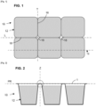
- THE figures 1 and 2 represent a pack 10 of jars 12 of food product.
- the food product can be a conventional food or a functional food.
- the food product can be any type of milk food.
- the product can be liquid, creamy, pasty or foamy.
- 'pack' should be understood as a set forming a sales lot, this set comprising several individual consumption units (each unit being referred to as a 'jar' or 'cup' here). Each individual consumption unit forms a food portion for an individual who, after consumption, throws the empty jar, that is to say the primary packaging, into a bin or a recycling circuit.
- a pack 10 of six pots 12 has been shown. It should however be understood that the number of pots 12 can be arbitrary, that is to say that the pack 10 can comprise 2 pots, 4 pots, 6 pots, 8 pots, even 9 pots, 10 pots, and even 12 pots.
- a reference plane PR is defined at the level of the upper surface of the pots 12, the reference plane PR comprising a longitudinal direction denoted L and a transverse direction denoted T.
- a vertical direction denoted Z substantially normal to the reference plane PR.
- the pots 12 of food product seen in cross section (perpendicular to the reference plane PR), may have a slightly conical shape like that illustrated in picture 2 .
- the pots 12 of food product can also be pots 12 with a convex side wall, which cannot be removed from the mold by a simple mould.
- the pots 12 are formed from a multi-housing container.
- the multi-housing container may be formed from plastic.
- the material used to constitute the multi-housing container may be polyethylene terephthalate (PET). It should be noted that either translucent PET or opaque PET can be used. Alternatively, the material used to constitute the multi-unit container can be Polypropylene (PP). The plastic material can be blown or injected into a mold in order to obtain the multi-unit container.
- the thickness denoted e2 of the plastic material of the container can be substantially uniform over the whole of the multi-unit container.
- the thickness e2 is typically between 0.6 mm and 2 mm, at least at the junction zones between the pots 12.
- the pots 12 are, following their formation, filled with food product and sealed by a cover sheet 14.
- the cover sheet 14 extends over the upper surface of the pots 12, that is to say parallel to the plane of PR reference.
- the lid sheet 14 has a thickness denoted e1 typically between 0.03 mm and 0.1 mm.
- the constituent material of the lid sheet 14 can be formed by a multilayer assembly, with a very thin layer of aluminum foil and a decorative and/or labeling layer.
- separation lines 16 are fusible lines which break when one pot 12 is tilted with respect to the other.
- the separation lines 16 make it possible to separate each of the pots 12 for individual consumption. It is also planned to form star-shaped holes 18 at the corners between four pots 12. These holes 18 further facilitate the separation of the pots 12.
- Pre-cut equipment 20 is used to form parting lines 16 and holes 18.
- Pre-cut equipment 20 is formed like a press.
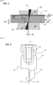
- the pre-cut equipment 20 essentially comprises an upper support plate 22 and a lower support plate 24. As seen in picture 3 , the packs 10 are received between the lower and upper support plates 22, 24.
- the upper support plate 22 and the lower support plate 24 have a relative movement in the direction of the vertical axis Z, ie the direction normal to the reference plane PR when a pack 10 of pots 12 is placed in the equipment 20.
- the upper support plate 22 can be moved along the vertical axis Z while the lower support plate 24 is fixed.
- the lower support plate 24 could be moved along the vertical axis Z, or the two lower and upper plates 22, 24 could be movable along the vertical axis Z.
- the upper support plate 22 receives one or more knives 26.
- the knives 26 extend above the parting lines 16.
- the knives 26 are adapted to form a precut groove from above along the parting line 16.
- the upper support plate 22 can also receive one or more star-shaped punches.
- the star-shaped punches are located at the level of the holes 18. The punches can then make it possible to cut the star-shaped holes 18.
- the lower support plate 24 receives at least one counter-blade 28.
- the counter-blades 28 extend below the lines of separation 16.
- the counter-blades 28 are adapted to form a precut groove from below along the separation line 16.
- the number of knives 26 and counter-blades 28 can correspond to the number of separation lines 16 to be produced, so that a single movement between the upper support plate and the lower support plate 22, 24 makes it possible to form all the separation lines 16 in a pack 10. It is also possible to provide enough knives 26 and counter-blades 28 to process several packs 10 at the same time. The productivity of the equipment 20 is increased.
- the depths of penetration of the knives 26 and the counter-blades 28 in the plastic material of the pack 10 are controlled.
- the control of the depths of penetration can be ensured in part or in whole thanks to the spacing and the relative displacement between the lower and upper support plates 22, 24.
- the spacing between the two support plates 22, 24 is fixed in the working position at the rib i.e. the sum of the thicknesses e1 of the lid sheet 14 and the thickness e2 of the plastic material at the junction between the pots 12.
- each knife 26 makes a groove over a height D3 from the top of the pack 10
- each counter-blade 28 makes a groove over a height D4 from the bottom of the pack 10.
- the height D3 of the groove made by the knife 26 is between 10% and 80% of the thickness e2 of the plastic material, more preferably between 20% and 60% of the thickness e2 of the plastic material.
- the knife 26 also makes it possible to fully groove the thickness e1 of the lid sheet 14.
- the height D4 of the groove made by the counter-blade 28 is for its part between 25% and 50% of the thickness e2 of plastic material, preferably between 30% and 40%. In this case, the height D3 of the groove made by the knife 26 is greater than the height D4 of the groove made by the counter-blade 28.
- Such grooves ensure good separation of the pots 12 along the lines of pre-cuts 16.
- a remaining distance D5 is defined which is not incised, neither by the knife 26, nor by the counter-blade 28. This remaining distance D5 is sufficient for the connection zones between the pots 12 to make it possible to lift the pack 10 by pots 12 only by one or two pots 12 without holding the other pots 12.
- the remaining distance D5 is between 20% and 60% of the thickness e2 of the plastic material.
- the remaining distance D5 is between 25% and 45% of the plastic material.
- a distance D6 separating the knife 26 and the counter-blade 28, measured along the direction normal to the vertical axis Z is between 0.003 and 0.1 mm.
- Such a distance D6, also called depinching makes it possible to increase the height of the grooves made in the plastic to make a total cut, i.e. to cross the whole of the rib e7 (the sum of the thicknesses e1 of the cover sheet 14 and the thickness e2 of the plastic material at the junction between the pots 12).
- the unpinching makes it possible to avoid mechanical contact between the knife 26 and the counter-blade 28 during a complete cut.
- the total cut can for example make it possible to carry out a separation between several packs 10 of jars 12 of food product.
- a knife 26 is described below. As illustrated in figure 6 , the knife 26 is here received in the upper plate 22 of the equipment 20, to be moved in the direction of the vertical axis Z and perform a pre-cut from above.
- the knife 26 essentially comprises a cutting part 32 intended to come into contact with the plastic, a body 30 ensuring the rigidity of the knife 26, and a cylindrical part 34 intended to allow the mounting of the knife 26 in the upper support plate 22 of the equipment. 20.
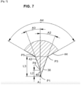
- the cutting part 32 extends along a longitudinal axis X. When the knife 26 is received in the upper support plate 22, the cutting part 32 extends along a line of separation 16. The cutting part 32 is intended to incise the packs 10 of pots 12 to form the lines of separation 16.
- the cutting part 32 extends on either side of a transverse axis A of the knife 26, from a free end of the cutting part 32 towards a connecting part 44, connecting the cutting part 32 to the body 30.
- the cutting part 32 defines a first portion 36, a second portion 38 and a third portion 40.
- the first portion 36 extends from a first point P1 forming the end of the cutting part 32 to a second point P2.
- a straight line connecting the first and second points P1, P2 forms with the transverse axis A a first angle A1 comprised between 20° and 40°.
- the first portion 36 extends over a distance L1, measured in the direction of the transverse axis A, of between 0.02 mm and 0.2 mm. The first portion 36 contributes to the mechanical strength of the knife 26 when the plastic is attacked by the knife 26.
- the second portion 38 extends from the second point P2 to a third point P3.
- a straight line connecting the second and third points P2, P3 forms with the transverse axis A a second angle A2 comprised between 15° and 25°.
- the second angle A2 makes it possible to reduce the penetration forces perceived by the cutting part 32.
- the second angle A2 participates in exerting a force on the lower support plate 24 to push the plastic against the counter-blade 28.
- the grooves from below, carried out by the counter-blade 28, are then improved.
- the cutting part 32 On the other side of the transverse axis A, that is to say on the side intended to face the counter-blade 28 when the knife 26 is received in the upper support plate 22, the cutting part 32 comprises a third portion 40 and a fourth portion 42.
- the third portion 40 extends from the first point P1 forming the end of the knife 26 and a fourth point P4 coinciding with the transverse axis A.
- the third portion 40 forms a flat face of the cutting part 32.
- the third portion 40 extends over a distance L2, measured in the direction of the transverse axis A, of between 0.2 and 0.8 mm.
- the fourth portion 42 extends from the fourth point P4 to a fifth point P5.
- a straight line connecting the fourth and fifth points P4, P5 forms with the transverse axis A a third angle A3 of between 15° and 25°.
- the fourth portion 42 makes it possible to balance the cutting force on either side of the transverse axis A, so as to reduce the flexion generated by the second angle A2 of the second portion 36.
- the fourth portion 42 also participates in pushing the plastic on the counter-blade 28, to improve the groove from below, in particular ensuring that the counter-blade 28 penetrates the plastic over the incise height D4 from below.
- the third and fifth points P3, P5 are symmetrical with respect to the transverse axis A.
- the connecting part 44 extends on either side of the transverse axis A from the points P3 and P5 to connect the cutting part 32 to the body 30 of the knife 26.
- a distance L3 between the first point P1 forming the end of the knife 26 and the third and fifth points P3, P5, measured in the direction of the transverse axis A is between 1.4 and 2mm. In other words, the height of the cutting part 32 is between 1.4 and 2 mm.
- the connecting part 44 extends symmetrically on either side of the transverse axis A according to an opening angle A4 of between 100° and 140°.
- the opening angle A4 makes it possible to stiffen the knife 26 to prevent bending of the knife 26.
- the body 30 extends along the longitudinal axis X.
- the body 30 has a polygonal section, to give the knife 26 sufficient rigidity to withstand the forces applied to the knife 26 when a pre-cut is made.
- the section of the body 30 is also adapted to be received in a housing or slide of the upper plate 22, in particular to ensure the correct orientation of the knife 26 in the upper plate 22
- the cutting part 32 can protrude from the housing or slide according to the height of the groove to be made.
- the cylindrical portion 34 extends from the body 30 in the direction of the transverse axis A.
- the cylindrical portion 34 extends from one side of the body 30 opposite to the cutting part 32.
- the axis of revolution of the cylindrical portion 34 corresponds to the transverse axis A.
- the cylindrical portion 34 can be received in a cylindrical housing formed in the upper plate 22 of the equipment 20.
- the cylindrical portion 34 can be identical regardless of the profile and shape of the part cutter 32, so that different knives 26 can be accommodated in the same cylindrical housing of the upper plate 22.
- a threaded hole 50 is here formed in the cylindrical portion 34.
- the threaded hole 50 extends along the axis of revolution A of the cylindrical portion 34, from an upper face of the cylindrical portion 34 towards the cutting part 32.
- the hole threaded 50 is adapted to receive an equipment retaining screw 20.
- the mounting of the cutting tool 30 by the retaining screw allows precise adjustment of the position of the knife 26 in the upper plate 22. Indeed, it is possible to finely adjust the incision height of the knife 26, by inserting the retaining screw more or less into the threaded hole 50.
- the cylindrical portion 34 here comprises a cylindrical groove 55, whose axis is the axis of revolution A of the cylindrical portion 34.
- the cylindrical groove 55 ensures good propagation of grease around the cylindrical portion 34, to smooth the relative movement between the cutting tool 30 and the upper support plate 22.
- a counter-blade 28 is described below.
- the counter-blade 28 is here received in the lower support plate 24 of the equipment 20 to make a pre-cut groove from below.
- the force applied by the knife 26 forces the plastic on the counter-blade 28. Thanks to the shape of the cutting part 32 of the knife 26 described below, the plastic is sufficiently pushed on the counter-blade 28 to perform a satisfactory and repeatable undergroove.
- the counter-blade 28 extends along a second longitudinal axis Y. When the counter-blade 28 is received in the lower support plate 24, the counter-blade 28 extends along a line of separation 16.
- the counter-blade 28 comprises an active part 54 intended to incise the plastic material, and a body 52 intended to be received in the lower plate 24.
- the active part 54 comprises an edge 56.
- the edge forms a flat face of the active part 54.
- the flat face is intended to face the knife 26 when the counter-blade 28 is received in the lower support plate 24.
- the active part 54 also defines a first segment 58.
- the first segment 58 extends from a first point P11 of the active part 54 forming the free end of the active part 54 and a second point P12.
- a straight line connecting the first and second points P11, P12 form, with the edge 56, a first angle A11 comprised between 20° and 40°.
- the first segment 58 extends over a distance L11, measured in the direction of the edge 56, of between 0.02 and 0.2 mm.
- the first segment 58 contributes to the mechanical strength of the counter-blade 28 when the plastic is attacked by the counter-blade 28.
- the active part 54 also defines a second segment 60.
- the second segment 60 extends from the second point P12 towards a third point P13, forming with the edge 56 a second angle A12 comprised between 15° and 25°.
- the second segment 60 contributes to reducing the penetration forces perceived by the active part 54, and therefore to reducing the bending.
- a clearance 62 extends from the third point P13 to connect the second segment 60 to the body 52 of the counter-blade 28.
- the edge 56 extends for its part in the continuity of one side of the body 52.
- the body 52 here has a substantially rectangular section.
- the body 52 can be received in a housing or slide of the lower plate 24 to ensure the correct orientation of the counter-blade 28 in the lower plate 24.
- the active part 54 can protrude from the housing or slide according to the height of the groove. to practise.
- the lower support plate 24 could receive one or more knives 26, and the upper support plate 22 could receive one or more counter-blades 28.
- This embodiment appears advantageous when the lower support plate 24 is movable in the direction of the vertical axis Z.
- the equipment 20 described below can be part of an installation.
- the installation may comprise a first piece of equipment configured to carry out a step of sealing the cover 14 on the pack 10 of pots 12 and a step of localized cooling of the junction zone between the pots 12 and a pre-cutting equipment 20 such as described above.
- the first equipment comprises sealing electrodes adapted to come into contact with the upper face of the pack 10, and a contact counterpart adapted to come into contact from below the junction zone between the pots 12.
- the contact counterpart is preferably thermo-regulated, for example by the circulation of an ice-cold water fluid or another low-temperature fluid in the counterpart.
- the sealing electrodes and the cooling counterpart sandwich the seal coated junction area. It is thus possible to guarantee a good pressure by the cooling counterpart and thus a good conduction heat transfer coefficient in the contact zone. As the cooling is localized, it is selective, it does not significantly affect the food product contained in the 12 pots.
Landscapes
- Engineering & Computer Science (AREA)
- Mechanical Engineering (AREA)
- Life Sciences & Earth Sciences (AREA)
- Forests & Forestry (AREA)
- Food-Manufacturing Devices (AREA)
- Packages (AREA)
- Knives (AREA)
- Nonmetal Cutting Devices (AREA)
- Auxiliary Devices For And Details Of Packaging Control (AREA)
- Control And Other Processes For Unpacking Of Materials (AREA)
- Supplying Of Containers To The Packaging Station (AREA)
Applications Claiming Priority (1)
| Application Number | Priority Date | Filing Date | Title |
|---|---|---|---|
| FR2114046A FR3130671B1 (fr) | 2021-12-20 | 2021-12-20 | Outils pour former une ligne de separation dans un pack de pots de produit alimentaire |
Publications (3)
| Publication Number | Publication Date |
|---|---|
| EP4201613A1 true EP4201613A1 (de) | 2023-06-28 |
| EP4201613B1 EP4201613B1 (de) | 2025-08-13 |
| EP4201613C0 EP4201613C0 (de) | 2025-08-13 |
Family
ID=81325589
Family Applications (1)
| Application Number | Title | Priority Date | Filing Date |
|---|---|---|---|
| EP22213804.2A Active EP4201613B1 (de) | 2021-12-20 | 2022-12-15 | Werkzeuge zur bildung einer trennlinie in einem paket aus lebensmitteltöpfen |
Country Status (11)
| Country | Link |
|---|---|
| US (1) | US12240646B2 (de) |
| EP (1) | EP4201613B1 (de) |
| JP (1) | JP2023091774A (de) |
| KR (1) | KR20230094168A (de) |
| AR (1) | AR128037A1 (de) |
| CA (1) | CA3185466A1 (de) |
| CL (1) | CL2022003644A1 (de) |
| ES (1) | ES3041784T3 (de) |
| FR (1) | FR3130671B1 (de) |
| IL (1) | IL299252A (de) |
| MX (1) | MX2022016571A (de) |
Families Citing this family (1)
| Publication number | Priority date | Publication date | Assignee | Title |
|---|---|---|---|---|
| JP7738955B1 (ja) * | 2025-07-14 | 2025-09-16 | 株式会社ファインテック | 刃物 |
Citations (4)
| Publication number | Priority date | Publication date | Assignee | Title |
|---|---|---|---|---|
| WO2004007156A1 (en) * | 2002-07-10 | 2004-01-22 | Ucb, S.A. | Apparatus and method for scoring a packaging film |
| DE202007013402U1 (de) * | 2007-09-25 | 2007-12-06 | Böhler-Uddeholm Precision Strip GmbH & Co. KG | Schneidlinie |
| EP3766799A1 (de) | 2019-07-17 | 2021-01-20 | Synerlink | Vorrichtung und verfahren zum bilden einer vorgeschnittenen linie in einer behältergruppe für lebensmittel |
| WO2021062295A1 (en) * | 2019-09-27 | 2021-04-01 | Mound Laser & Photonics Center, Inc. | Chemically sharpening blades |
Family Cites Families (4)
| Publication number | Priority date | Publication date | Assignee | Title |
|---|---|---|---|---|
| US6070507A (en) * | 1997-03-03 | 2000-06-06 | Abbott Laboratories | Method for punching a sealed package from first and second webs |
| US7051911B2 (en) * | 2001-12-21 | 2006-05-30 | Eastman Kodak Company | Apparatus and method for cutting sheet materials |
| US7455004B2 (en) * | 2003-03-06 | 2008-11-25 | Alcoa Inc. | Apparatus and method for cutting sheet material |
| JP2008183094A (ja) | 2007-01-29 | 2008-08-14 | Kai R & D Center Co Ltd | カッターの刃 |
-
2021
- 2021-12-20 FR FR2114046A patent/FR3130671B1/fr active Active
-
2022
- 2022-12-15 ES ES22213804T patent/ES3041784T3/es active Active
- 2022-12-15 EP EP22213804.2A patent/EP4201613B1/de active Active
- 2022-12-16 MX MX2022016571A patent/MX2022016571A/es unknown
- 2022-12-19 KR KR1020220178259A patent/KR20230094168A/ko not_active Ceased
- 2022-12-19 CL CL2022003644A patent/CL2022003644A1/es unknown
- 2022-12-19 IL IL299252A patent/IL299252A/en unknown
- 2022-12-19 JP JP2022202289A patent/JP2023091774A/ja active Pending
- 2022-12-20 CA CA3185466A patent/CA3185466A1/fr active Pending
- 2022-12-20 US US18/068,729 patent/US12240646B2/en active Active
- 2022-12-20 AR ARP220103516A patent/AR128037A1/es not_active Application Discontinuation
Patent Citations (4)
| Publication number | Priority date | Publication date | Assignee | Title |
|---|---|---|---|---|
| WO2004007156A1 (en) * | 2002-07-10 | 2004-01-22 | Ucb, S.A. | Apparatus and method for scoring a packaging film |
| DE202007013402U1 (de) * | 2007-09-25 | 2007-12-06 | Böhler-Uddeholm Precision Strip GmbH & Co. KG | Schneidlinie |
| EP3766799A1 (de) | 2019-07-17 | 2021-01-20 | Synerlink | Vorrichtung und verfahren zum bilden einer vorgeschnittenen linie in einer behältergruppe für lebensmittel |
| WO2021062295A1 (en) * | 2019-09-27 | 2021-04-01 | Mound Laser & Photonics Center, Inc. | Chemically sharpening blades |
Also Published As
| Publication number | Publication date |
|---|---|
| IL299252A (en) | 2023-07-01 |
| US20230192341A1 (en) | 2023-06-22 |
| ES3041784T3 (en) | 2025-11-14 |
| FR3130671A1 (fr) | 2023-06-23 |
| CA3185466A1 (fr) | 2023-06-20 |
| JP2023091774A (ja) | 2023-06-30 |
| EP4201613B1 (de) | 2025-08-13 |
| KR20230094168A (ko) | 2023-06-27 |
| FR3130671B1 (fr) | 2025-01-03 |
| EP4201613C0 (de) | 2025-08-13 |
| AR128037A1 (es) | 2024-03-20 |
| CL2022003644A1 (es) | 2023-09-29 |
| US12240646B2 (en) | 2025-03-04 |
| MX2022016571A (es) | 2023-06-21 |
Similar Documents
| Publication | Publication Date | Title |
|---|---|---|
| EP3766799A1 (de) | Vorrichtung und verfahren zum bilden einer vorgeschnittenen linie in einer behältergruppe für lebensmittel | |
| EP0251932A1 (de) | Verfahren und Vorrichtung zum Heissverformen und Aufbringen eines thermoplastischen Deckels auf einen Behälter und Behälter, versehen mit solch einem Deckel | |
| EP4201613B1 (de) | Werkzeuge zur bildung einer trennlinie in einem paket aus lebensmitteltöpfen | |
| EP3162553B1 (de) | Verpackung as pappe und verfahren zur deren herstellung | |
| CH463376A (fr) | Emballage comportant une boîte en matière plastique et deux couvercles | |
| FR3002207A1 (fr) | Conditionnement d'un groupe d'au moins deux recipients en matiere plastique | |
| EP2114572B1 (de) | Verpackungstube für eine vordefinierte menge einer biologischen substanz zur lagerung bei niedriger temperatur und system damit | |
| JP7273486B2 (ja) | スリットバルブ付容器蓋 | |
| EP1237414A1 (de) | Pressform die nahrungsmittel wie schinken während ihres kochvorgangs enthalten mit beibehaltung der pressung | |
| WO2023041865A1 (fr) | Équipement avec un couteau en "v" pour la prédécoupé de dans un pack de pots | |
| EP2368807B1 (de) | Verschlussvorrichtung für quaderförmige Verpackungen | |
| EP3902751B1 (de) | Portionsbeutel mit einfacher öffnung für erwachsene | |
| FR2652061A1 (fr) | Dispositif de conditionnement pour produit a consistance de gel solide. | |
| EP2615214A1 (de) | Vorrichtung zum Sammeln von Regenwasser | |
| FR2704206A1 (fr) | Récipient en carton avec bec verseur incorporé. | |
| FR3061155A1 (fr) | Emballage pour le conditionnement d'un produit, notamment alimentaire | |
| EP4175890B1 (de) | Metallkonservierungsdose mit einem metalldosenkörper und einem metalldeckel, die durch eine abziehbare lasche miteinander verbunden sind | |
| FR2985061A1 (fr) | Adaptateur de format pour carte a cote convexe | |
| EP3630071A1 (de) | Gekerbte tablette | |
| FR3146611A1 (fr) | Outil de découpe à butées mobiles | |
| FR3126216A3 (fr) | Recipient en papier en forme de batonnet | |
| FR2891257A1 (fr) | Procede de conditionnement d'un produit alimentaire moulable notamment un produit laitier, et emballage d'un tel produit | |
| FR3126217A3 (fr) | Recipient en papier en forme de batonnet | |
| EP2622059B1 (de) | Einheit zum durchstechen und formen mittels prägen, pressen oder stanzen zur herstellung von durchgestochenen seifensstücken sowie verfahren zur herstellung derartiger stücke, im besonderen in einer derartigen einheit | |
| FR2814440A1 (fr) | Emballage souple a ouverture facile, procede et installation de fabrication |
Legal Events
| Date | Code | Title | Description |
|---|---|---|---|
| PUAI | Public reference made under article 153(3) epc to a published international application that has entered the european phase |
Free format text: ORIGINAL CODE: 0009012 |
|
| STAA | Information on the status of an ep patent application or granted ep patent |
Free format text: STATUS: THE APPLICATION HAS BEEN PUBLISHED |
|
| AK | Designated contracting states |
Kind code of ref document: A1 Designated state(s): AL AT BE BG CH CY CZ DE DK EE ES FI FR GB GR HR HU IE IS IT LI LT LU LV MC ME MK MT NL NO PL PT RO RS SE SI SK SM TR |
|
| STAA | Information on the status of an ep patent application or granted ep patent |
Free format text: STATUS: REQUEST FOR EXAMINATION WAS MADE |
|
| 17P | Request for examination filed |
Effective date: 20231207 |
|
| RBV | Designated contracting states (corrected) |
Designated state(s): AL AT BE BG CH CY CZ DE DK EE ES FI FR GB GR HR HU IE IS IT LI LT LU LV MC ME MK MT NL NO PL PT RO RS SE SI SK SM TR |
|
| GRAP | Despatch of communication of intention to grant a patent |
Free format text: ORIGINAL CODE: EPIDOSNIGR1 |
|
| STAA | Information on the status of an ep patent application or granted ep patent |
Free format text: STATUS: GRANT OF PATENT IS INTENDED |
|
| INTG | Intention to grant announced |
Effective date: 20250325 |
|
| GRAS | Grant fee paid |
Free format text: ORIGINAL CODE: EPIDOSNIGR3 |
|
| GRAA | (expected) grant |
Free format text: ORIGINAL CODE: 0009210 |
|
| STAA | Information on the status of an ep patent application or granted ep patent |
Free format text: STATUS: THE PATENT HAS BEEN GRANTED |
|
| AK | Designated contracting states |
Kind code of ref document: B1 Designated state(s): AL AT BE BG CH CY CZ DE DK EE ES FI FR GB GR HR HU IE IS IT LI LT LU LV MC ME MK MT NL NO PL PT RO RS SE SI SK SM TR |
|
| REG | Reference to a national code |
Ref country code: GB Ref legal event code: FG4D Free format text: NOT ENGLISH |
|
| REG | Reference to a national code |
Ref country code: CH Ref legal event code: EP |
|
| REG | Reference to a national code |
Ref country code: DE Ref legal event code: R096 Ref document number: 602022019347 Country of ref document: DE |
|
| REG | Reference to a national code |
Ref country code: IE Ref legal event code: FG4D Free format text: LANGUAGE OF EP DOCUMENT: FRENCH |
|
| U01 | Request for unitary effect filed |
Effective date: 20250904 |
|
| U07 | Unitary effect registered |
Designated state(s): AT BE BG DE DK EE FI FR IT LT LU LV MT NL PT RO SE SI Effective date: 20250910 |
|
| REG | Reference to a national code |
Ref country code: ES Ref legal event code: FG2A Ref document number: 3041784 Country of ref document: ES Kind code of ref document: T3 Effective date: 20251114 |
|
| U20 | Renewal fee for the european patent with unitary effect paid |
Year of fee payment: 4 Effective date: 20251121 |
|
| PG25 | Lapsed in a contracting state [announced via postgrant information from national office to epo] |
Ref country code: IS Free format text: LAPSE BECAUSE OF FAILURE TO SUBMIT A TRANSLATION OF THE DESCRIPTION OR TO PAY THE FEE WITHIN THE PRESCRIBED TIME-LIMIT Effective date: 20251213 |
|
| PG25 | Lapsed in a contracting state [announced via postgrant information from national office to epo] |
Ref country code: NO Free format text: LAPSE BECAUSE OF FAILURE TO SUBMIT A TRANSLATION OF THE DESCRIPTION OR TO PAY THE FEE WITHIN THE PRESCRIBED TIME-LIMIT Effective date: 20251113 |
|
| PG25 | Lapsed in a contracting state [announced via postgrant information from national office to epo] |
Ref country code: HR Free format text: LAPSE BECAUSE OF FAILURE TO SUBMIT A TRANSLATION OF THE DESCRIPTION OR TO PAY THE FEE WITHIN THE PRESCRIBED TIME-LIMIT Effective date: 20250813 |
|
| PG25 | Lapsed in a contracting state [announced via postgrant information from national office to epo] |
Ref country code: GR Free format text: LAPSE BECAUSE OF FAILURE TO SUBMIT A TRANSLATION OF THE DESCRIPTION OR TO PAY THE FEE WITHIN THE PRESCRIBED TIME-LIMIT Effective date: 20251114 |
|
| PG25 | Lapsed in a contracting state [announced via postgrant information from national office to epo] |
Ref country code: PL Free format text: LAPSE BECAUSE OF FAILURE TO SUBMIT A TRANSLATION OF THE DESCRIPTION OR TO PAY THE FEE WITHIN THE PRESCRIBED TIME-LIMIT Effective date: 20250813 |
|
| PG25 | Lapsed in a contracting state [announced via postgrant information from national office to epo] |
Ref country code: RS Free format text: LAPSE BECAUSE OF FAILURE TO SUBMIT A TRANSLATION OF THE DESCRIPTION OR TO PAY THE FEE WITHIN THE PRESCRIBED TIME-LIMIT Effective date: 20251113 |