EP4201288A1 - Suction robot - Google Patents
Suction robot Download PDFInfo
- Publication number
- EP4201288A1 EP4201288A1 EP22208210.9A EP22208210A EP4201288A1 EP 4201288 A1 EP4201288 A1 EP 4201288A1 EP 22208210 A EP22208210 A EP 22208210A EP 4201288 A1 EP4201288 A1 EP 4201288A1
- Authority
- EP
- European Patent Office
- Prior art keywords
- bearing
- cleaning roller
- vacuum cleaner
- robotic vacuum
- roller
- Prior art date
- Legal status (The legal status is an assumption and is not a legal conclusion. Google has not performed a legal analysis and makes no representation as to the accuracy of the status listed.)
- Pending
Links
- 238000004140 cleaning Methods 0.000 claims abstract description 119
- 241000446313 Lamella Species 0.000 claims description 14
- 229920001971 elastomer Polymers 0.000 claims description 12
- 210000000078 claw Anatomy 0.000 claims description 10
- 238000012545 processing Methods 0.000 claims description 5
- 210000004209 hair Anatomy 0.000 description 26
- 238000013016 damping Methods 0.000 description 8
- 239000002775 capsule Substances 0.000 description 7
- 239000000428 dust Substances 0.000 description 6
- 230000000149 penetrating effect Effects 0.000 description 4
- 238000011161 development Methods 0.000 description 2
- 230000018109 developmental process Effects 0.000 description 2
- 230000000694 effects Effects 0.000 description 2
- 238000013508 migration Methods 0.000 description 2
- 230000005012 migration Effects 0.000 description 2
- 239000004753 textile Substances 0.000 description 2
- 229920002943 EPDM rubber Polymers 0.000 description 1
- 235000019687 Lamb Nutrition 0.000 description 1
- 229920000459 Nitrile rubber Polymers 0.000 description 1
- 229910000831 Steel Inorganic materials 0.000 description 1
- 230000005540 biological transmission Effects 0.000 description 1
- 230000006835 compression Effects 0.000 description 1
- 238000007906 compression Methods 0.000 description 1
- 230000001419 dependent effect Effects 0.000 description 1
- 238000005553 drilling Methods 0.000 description 1
- 239000013013 elastic material Substances 0.000 description 1
- 239000000806 elastomer Substances 0.000 description 1
- 210000003746 feather Anatomy 0.000 description 1
- 210000004905 finger nail Anatomy 0.000 description 1
- 238000009408 flooring Methods 0.000 description 1
- 238000009434 installation Methods 0.000 description 1
- 238000012423 maintenance Methods 0.000 description 1
- 239000002184 metal Substances 0.000 description 1
- 239000004033 plastic Substances 0.000 description 1
- 229920001470 polyketone Polymers 0.000 description 1
- 229920001296 polysiloxane Polymers 0.000 description 1
- 238000010079 rubber tapping Methods 0.000 description 1
- 238000000926 separation method Methods 0.000 description 1
- 239000010959 steel Substances 0.000 description 1
- 229920002803 thermoplastic polyurethane Polymers 0.000 description 1
- 238000012546 transfer Methods 0.000 description 1
- 238000004804 winding Methods 0.000 description 1
Images


Classifications
-
- A—HUMAN NECESSITIES
- A47—FURNITURE; DOMESTIC ARTICLES OR APPLIANCES; COFFEE MILLS; SPICE MILLS; SUCTION CLEANERS IN GENERAL
- A47L—DOMESTIC WASHING OR CLEANING; SUCTION CLEANERS IN GENERAL
- A47L9/00—Details or accessories of suction cleaners, e.g. mechanical means for controlling the suction or for effecting pulsating action; Storing devices specially adapted to suction cleaners or parts thereof; Carrying-vehicles specially adapted for suction cleaners
- A47L9/02—Nozzles
- A47L9/04—Nozzles with driven brushes or agitators
- A47L9/0455—Bearing means therefor
-
- A—HUMAN NECESSITIES
- A47—FURNITURE; DOMESTIC ARTICLES OR APPLIANCES; COFFEE MILLS; SPICE MILLS; SUCTION CLEANERS IN GENERAL
- A47L—DOMESTIC WASHING OR CLEANING; SUCTION CLEANERS IN GENERAL
- A47L9/00—Details or accessories of suction cleaners, e.g. mechanical means for controlling the suction or for effecting pulsating action; Storing devices specially adapted to suction cleaners or parts thereof; Carrying-vehicles specially adapted for suction cleaners
- A47L9/02—Nozzles
- A47L9/04—Nozzles with driven brushes or agitators
- A47L9/0461—Dust-loosening tools, e.g. agitators, brushes
- A47L9/0466—Rotating tools
- A47L9/0477—Rolls
-
- A—HUMAN NECESSITIES
- A47—FURNITURE; DOMESTIC ARTICLES OR APPLIANCES; COFFEE MILLS; SPICE MILLS; SUCTION CLEANERS IN GENERAL
- A47L—DOMESTIC WASHING OR CLEANING; SUCTION CLEANERS IN GENERAL
- A47L2201/00—Robotic cleaning machines, i.e. with automatic control of the travelling movement or the cleaning operation
Definitions
- the invention relates to a robotic vacuum cleaner for autonomous cleaning of floor surfaces, the robotic vacuum cleaner having at least one cleaning roller which extends transversely to a working direction and has an elongated roller body, the cleaning roller being removable from the robotic vacuum cleaner for replacement and/or cleaning and being reinsertable, the cleaning roller used in the vacuum robot is rotatably driven on a first bearing side via a drive pin of the cleaning roller, the cleaning roller used in the vacuum robot being mounted on a second bearing side via a movable bearing.
- Vacuum robots are used in private households and in industry for the autonomous cleaning of surfaces such as textile floor coverings and smooth floors.
- Robot vacuums of the type mentioned at the outset are known from the prior art.
- a disadvantage of the previously known robotic vacuum cleaners is that the cleaning roller is not inserted in a user-friendly manner and the cleaning roller bearing does not have sufficient damping, so that the robot vacuum cleaner is operated with considerable noise due to the rotatable, driven cleaning rollers.
- the invention therefore faces the problem of specifying an improved vacuum robot.
- changing and/or cleaning the cleaning roller should be simplified and the acoustics of the vacuum robot during operation should be improved in a simple manner, so that the noise generated by the rotating cleaning roller is reduced.
- this problem is solved by a vacuum robot having the features of claim 1 .
- the floating bearing of the cleaning roller has a spring-loaded bearing bush, the bearing bush of the cleaning roller used being accommodated in a bearing mount of the vacuum robot, a spring displacing the bearing bush axially by means of spring force on the roller body of the cleaning roller against the bearing mount, the spring force of the spring displacing the If the drive pin of the cleaning roller used is displaced axially against a drive pin receptacle of the robot vacuum, the installation of the cleaning roller in the robot vacuum can be simplified and sufficient damping of the bearing can also be achieved in a simple manner, which enables a significant noise reduction for the operation of the robot vacuum. With the bearing bush of the floating bearing damping of the storage can also be done without changing the drive pin and the Drive pin recording can be achieved.
- the spring-loaded bearing bush on the floating bearing still ensures damping of the bearing on both sides of the bearing, in that the spring force of the spring provides damping support for the bearing bush in the bearing mount, with the spring force of the spring also providing damping support for the bearing bush in the bearing mount when the bearing bush is supported in the bearing mount
- the spring force of the spring provides damping support for the bearing bush in the bearing mount
- the spring force of the spring also providing damping support for the bearing bush in the bearing mount when the bearing bush is supported in the bearing mount
- the floor surface can be covered by a textile floor covering such as a rug or carpeting or by a hard floor such as e.g. B. a wooden parquet, laminate or PVC flooring can be formed.
- the robotic vacuum cleaner has a fan for generating a vacuum, through which the robotic vacuum cleaner picks up dust and dirt from the floor surface. So that the cleaning and care of the floor covering is carried out as effectively as possible by the vacuum robot, a suction mouth of the vacuum robot is elongate and runs essentially transversely to the processing direction. Elongated in this context means that the preferably substantially rectangular suction mouth has a greater length transverse to the processing direction than width in the processing direction. It can have a dust collection chamber in which the dust collected can be collected, for example, in a dust bag or dust container.
- the bearing bush on the loose bearing side is preferably mounted elastically via a compression spring, which presses axially on the roller body. This promotes low vibration of the cleaning roller during operation due to the firm, pre-tensioned and dampened seat of the cleaning roller in the vacuum robot.
- the bearing bush can be made of elastomer, for example EPDM, NBR, TPU or silicone, but also plastic with good damping properties, for example POM or polyketone.
- the bearing bush consists of a combination of a hard component and a soft component.
- the drive pin has a plurality of claws, these forming first, axial sliding surfaces and first, tangential contact surfaces, with the drive pin receptacle having second, axial Forms sliding surfaces and second, tangential contact surfaces, with the axial sliding surfaces being designed to slide past one another when the cleaning roller is inserted into the vacuum robot and to position the tangential contact surfaces against one another, with the positioned contact surfaces being set up to apply a driving force to the cleaning roller used to rotate the To transfer cleaning roller from the drive pin receptacle on the drive pin.
- the drive pin and the drive pin receptacle which is mechanically connected to a drive motor, preferably form mutually corresponding claws with the sliding surfaces and the contact surfaces.
- the claws are preferably formed by circular sector sections (pieces of cake) bisected diagonally in the axial direction.
- the sliding surfaces come into contact with one another independently of the angular position of the roller body and slide on one another into a contact position in which the contact surfaces contact one another.
- the edges of the self-locating claws between the sliding surfaces and the gripping surfaces are preferably rounded, so that the drive pin and the drive pin receptacle can be prevented from getting caught when the cleaning roller is inserted.
- the sliding surfaces of the drive pin and drive pin mount align themselves with one another when the cleaning roller is inserted into the vacuum robot by rotating the drive pin mount about the drive axis. Then, when the cleaning roller is inserted, the sliding surfaces slide against one another until the tangential contact surfaces of the drive pin and the drive pin receptacle touch and create a non-positive connection.
- the bearing bush has a centering pin, which is designed to be guided when inserting the cleaning roller in a pin guide of the bearing mount to a pin receiving hole of the bearing mount, in which the centering pin engages.
- the centering pin With the centering pin, it is easy to precisely align the cleaning roller when inserting it into the vacuum robot, since the centering pin is guided in the pin guide.
- the locking of the centering pin by means of the spring force of the spring enables an optimal alignment of the bearing bush in the bearing mount of the vacuum robot during the cleaning operation.
- haptic feedback is also given that the cleaning roller has been inserted correctly.
- the main part of the latching effect of the bearing bush takes place via its conical contact surfaces.
- the pin guide is preferably formed by a funnel-shaped groove in the housing of the vacuum robot.
- the arrangement of the centering pin in the pin receiving hole prevents movement of the bearing bush in the vertical direction relative to the drive pin receptacle. As a result, the centering pin locks the bearing bush in an operating position in the vacuum robot.
- the bearing bush has at least one conical contact surface for support in the bearing mount.
- the conical contact surface is used to guide hair or threads on the contact surface to the outside as far as possible when cleaning the floor surface.
- the conical contact surface for support is preferably designed to taper towards the bearing mount.
- the bearing bush has a collar which adjoins the largest radius of the contact surface and protrudes at least radially from the contact surface.
- the collar is used for the positive connection of the bearing bush with the roller body.
- the collar advantageously prevents the bearing bush from loosening on its own, for example during maintenance of the cleaning roller.
- the collar forms an increase in diameter so that hair is prevented from migrating into the area between the bearing bush and the roller body.
- the bearing bush has a second collar which extends inwards on the bearing bush in the direction of the axis.
- the bearing bush is rotatably mounted on a bearing shaft via a ball or slide bearing, the bearing shaft being guided in an axially displaceable manner relative to the roller body by means of the spring.
- the ball or slide bearing which is protected in the bearing bush, allows the bearing bush to rotate relative to the roller body, so that the bearing bush can remain firmly positioned in the bearing mount for the rotation of the cleaning roller.
- the bearing shaft which is guided axially in the roller body, allows the spring deflection of the spring-loaded bearing bush.
- the bearing shaft can be a component made of metal, preferably steel, so that stable storage is made possible.
- the ball bearing can be mounted with play on the bearing shaft and preferably removed together from the bearing shaft for cleaning against a small resistance of the form fit of the bearing shaft with the bearing bush.
- the cylindrical roller body has a base diameter, the roller body having projections adjoining the circle of intersection, which protrude at least radially from the lateral surface of the roller body. These projections are intended to prevent hair and threads that wind up around the cleaning roller when cleaning the floor surface from migrating beyond the cutting circles of the cylindrical roller body into the bearing sides.
- the overhangs that protrude radially from the outer surface of the roller body have a larger diameter than the base diameter of the roller body, which prevents the hair from migrating and threads made more difficult over this increased diameter. This allows the bearing sides to be effectively protected against clogging with tufts of hair and threads.
- the cleaning roller has several rubber lamellas that protrude radially from the roller body and form outer lamella edges, the elongate rubber lamellas having projections adjoining the axial lamella ends, which protrude at least radially opposite the outer lamella edges.
- These projections prevent hair and threads that wind up around the cleaning roller when cleaning the floor surface from migrating beyond the ends of the slats into the bearing sides.
- the overhangs that protrude radially from the outer edges of the slats prevent hair and threads from migrating beyond the ends of the slats due to the larger radial distance to the roller body. This allows the bearing sides to be effectively protected against clogging with tufts of hair and threads.
- a preferred embodiment of the invention provides that the projections engage in runners of the vacuum robot, with the runners forming undercuts.
- the undercuts prevent hair and threads that wind around the cleaning roller when cleaning the floor surface from migrating beyond the overhangs into the bearing sides.
- the running channels preferably enclose the projections at an angle of at least 180°.
- the rotationally symmetrical raceways nevertheless offer sufficient play so that the projections in the raceways can rotate freely when the cleaning roller rotates.
- the figure 1 shows a robotic vacuum cleaner 1 from the underside 47. It can be seen in this representation that the robotic vacuum cleaner 1 has two cleaning rollers 4 extending transversely to the working direction 3. These cleaning rollers 4 have an elongated roller body 5. For changing and/or cleaning, the cleaning rollers 4 can be removed from the vacuum robot 1 and also reinserted.
- the cleaning roller 4 used in the vacuum robot 1 is on a first bearing side 6 ( 20 ) via a drive pin 7 ( 20 ) of the cleaning roller 4 rotatably driven on the vacuum robot 1.
- the axially opposite second bearing side 8 will be described in more detail, on which the cleaning roller 4 is mounted via a floating bearing 9 on the vacuum robot 1 .
- FIG 2 is a cleaning roller 4 according to FIG figure 2 partially shown in a single view.
- the spring-loaded bearing bushing 10 of the floating bearing 9 ( 2 ) recognizable.
- the bearing bush 10 is as shown in figure 2 to see, recorded in a bearing mount 11 of the vacuum robot 1.
- the figure 3 shows a sectional view through the bearing bush 10 according to FIG figure 2 .
- the bearing bushing 10 can be displaced on the roller body 5 by means of a spring 12 .
- the spring 12 presses the bearing bushing 10 against the bearing mount 11 ( 1 ) of floating bearing 9 ( 1 ).
- the spring force F of the spring 12 also presses the drive pin 7 ( 20 ) of the cleaning roller 4 used axially against a drive pin receptacle 13 ( 20 ) of the vacuum robot 1.
- the sectional view also shows that the bearing bushing 10 is rotatably mounted on a bearing shaft 25 via a ball or plain bearing 24 .
- the ball or slide bearing 24 is protected in the bearing bush 10 so that hair and threads that wind around the cleaning roller 4 cannot reach the ball or slide bearing 24 .
- the bearing shaft 25 can be displaced axially by means of the spring 12 and is guided in the roller body 5 in a displaceable manner for this purpose.
- the bearing shaft 25 advantageously has a disc-shaped step, which counteracts the migration of threads and hair.
- the ball or sliding bearing 24 accommodated in the bearing bushing 10 allows the bearing bushing 10 to rotate in relation to the roller body 5, so that the bearing bushing 10 is held firmly in the bearing seat 11 ( 1 ) can remain positioned.
- the bearing bush 10 is supported in the bearing mount 11 ( 1 ) via conical contact surfaces 22. These conical contact surfaces 22 serve to guide hair or threads on the contact surface 22 to the outside as far as possible when cleaning the floor surface. For this purpose, the conical contact surface 22 runs to support the bearing mount 11 ( 1 ) to a point.
- the bearing bush 10 is inserted into an axial bore 56 and the axial roller body 5 is passed over the bearing bush 10 .
- a collar 23 which protrudes radially from the contact surface 22 also adjoins the largest radius of the contact surface 22 .
- the collar 23 thus forms an increase in diameter so that hair is prevented from migrating into the area between the bearing bush 10 and the roller body 5 .
- the ball or sliding bearing 24 can be removed from the bearing shaft 25 together with the bearing bushing 10 .
- the bearing bushing 10 has a shoulder 49 on the contact surfaces 22, which can be gripped behind with a fingernail to remove the bearing bushing 10 together with the ball or sliding bearing 24 from the bearing shaft 25.
- the axial freedom of movement of the bearing shaft 25 in the roller body 5 is limited by a slot 50 in the bearing shaft 25 and a stop element 51 which dips into it and which is fastened to the roller body 5 .
- the stop element 51 can be a metric screw, a self-tapping screw or a simple bolt with a locking geometry for a roller bore.
- the figure 4 shows a first embodiment of the contact surfaces 22 of the bearing bush 10.
- the contact surfaces 22 are smooth and rotationally symmetrical.
- FIG. 5 Out of figure 5 a second embodiment of the contact surfaces 22 of the bearing bush 10 can be seen.
- elevations 52 are provided in the form of nubs on the contact surfaces 22 so that a form fit with the correspondingly designed bearing mount 11 ( 1 ) can be produced.
- the surveys 52 prevent the bushing 10 in hair between the bearing bush 10 and the bearing seat 11 ( 2 ) slipped through and the bearing mount 11 was damaged.
- the figure 6 discloses a third embodiment of the contact surfaces 22 of the bearing bush 10.
- the elevations 52 are designed as webs which fit into correspondingly designed grooves in the bearing mount 11 ( 1 ) intervene and create a form fit.
- the elevations 52 ensure that if there are hairs between the bearing bushing 10 and the bearing mount 11 ( 1 ) does not slip and the bearing mount 11 is damaged.
- the position of the bearing bush defined by the elevation has an advantageous effect on the vibration behavior of the cleaning roller.
- FIG 7 the bearing seat 11 of the floating bearing 9 is shown.
- a cleaning roller 4 is partially shown before it is inserted into the robotic vacuum cleaner 1 .
- a centering pin 19 on the bearing bush 10 can also be seen here.
- the block arrows indicate that the centering pin 19 is designed to be guided in a pin guide 20 of the bearing mount 11 to a pin receiving hole 21 of the bearing mount 11 when the cleaning roller 4 is inserted.
- the figure 8 shows the centering pin 19 snapped into the pin receiving hole 21.
- the centering pin 19 can be used to precisely align the cleaning roller 4 when it is inserted into the vacuum robot 1, since the centering pin 19 is guided over the pin guide.
- the locking of the centering pin 19 is achieved via the spring force of the spring 12 and enables an optimal alignment of the bearing bush 10 in the bearing mount 11 of the vacuum robot 1 during the cleaning operation.
- the locking of the centering pin 19 provides haptic feedback that the cleaning roller 4 has been inserted correctly.
- FIG 9 a view of the open loose bearing 9 with the bearing mount 11 is shown.
- the bearing mount 11 formed in the housing of the vacuum robot 1 can be closed radially via a separate capsule part 53 .
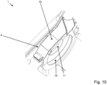
- the capsule part 53 is placed on the floating bearing 9 on the bearing mount 11, as shown in figure 10 to see.
- the capsule part 53 can be pivoted on the vacuum robot 1 so that it can be used to remove the cleaning roller 4 ( 2 ) can be swung open.
- the capsule part 53 can then simply be pivoted closed again after the cleaning roller 4 has been inserted.
- the capsule part 53 can then be latched onto the vacuum robot 1 .
- FIG 11 an embodiment is shown in which rubber lamellae 30 projecting radially from the roller body 5 of the cleaning roller 1 form an undercut 34 with the bearing bush 10 . In this way, an unintentional loosening of the bearing bushing 10 together with the ball or sliding bearing 24 can be avoided.
- the figure 12 shows an embodiment of the loose bearing 9 in which the rubber lamellae 30 protruding radially from the roller body 5 have projections 32 at the lamellar ends 31 .
- the elongate rubber lamellas 30 each form lamella outer edges 29 along the cleaning roller 1.
- the projections 32 adjoining the axial lamella ends 31 protrude radially opposite the lamella outer edges 29.
- These projections 32 on the rubber slats 30 prevent hair and threads from wrapping around the cleaning roller 4 when cleaning the floor surface and from migrating beyond the slat ends 31 into the bearing sides 6, 8.
- the bearing sides 6, 8 are thus effectively protected against clogging with tufts of hair and threads.
- the projections 32 engage in runners 33, the runners 33 forming undercuts 34 for this purpose.
- the undercuts 34 ensure that hair and threads that wind up around the cleaning roller 4 when cleaning the floor surface do not migrate beyond the projections 32 into the bearing sides 6 , 8 .
- the running grooves 33 preferably enclose the projections 32, as shown, with an angle of at least 180°.
- the rotationally symmetrical running channels 33 are formed by the housing of the robotic vacuum cleaner 1 and the capsule part 53 which secures the cleaning roller 4 in the robotic vacuum cleaner 1 .
- the labyrinthine structure of the projection 32 and the channel 33 effectively prevents threads and hair from penetrating into the bearing of the cleaning roller 4.
- FIG 13 another embodiment of the floating bearing 9 is shown.
- the bearing seat 11 has a star structure 54 on the support for the bearing bush 10 ( 14 ).
- the corresponding bearing bushing 10 also has a star structure 54 as elevations on the conical contact surface 22 .
- the cleaning roller 4 shown in part can be found in the bearing mount 11 according to FIG figure 13 a particularly light form fit via the star structures 54 which correspond to one another. This enables the bearing bushing 10 to be seated in a defined manner in the radial direction in the bearing receptacle 11 . As a result, the bearing bushing 10 does not slip through in the event of friction in the floating bearing 9.
- the star structure 54 is preferably formed by rotationally arranged cylindrical deduction bodies (female) of the conical contact surface 22 of the bearing bushing 10 or raised structures (male) on the bearing mount 11. The deduction bodies run out in the direction of the axis of rotation of the cleaning roller 4 .
- the figure 15 shows a sectional view through the movable bearing 9.
- additional projections 27 are provided on the cylindrical roller body 5. From the base diameter d_mb1 of the roller body 5, which in figure 16 is drawn in, these projections 27 protrude radially from the outer surface 28 of the roller body 5 . Up to diameter d_mb4 equal to or greater than diameter d_c ( 16 ) of the undercut 34 of the running channel 33.
- the projection 27 adjoining the cutting circle 26 protrudes with the diameter d_mb3 ( 16 ) under the undercut 34 in the running channel 33, the diameter d_mb3 ( 16 ) is smaller than the diameter d_c ( 16 ) of the undercut 34, but larger than the diameter d_mb2 ( 16 ) of the projection 27 in front of the undercut 34.
- the bearing bush 10 is advantageously composed of two components. A firmer component forms the centering pin 19 , while a softer component forms the collar 23 adjoining the contact surface 22 .
- an elastic retaining collar 57 ( 16 ) is provided, which is intended to prevent the bearing bushing 10 from becoming detached from the bearing shaft 25 .
- the diameter d_b1 of the adjoining collar 23 is larger than the diameters d_b2 and d_b3 of the conical contact surface 22. This also effectively prevents hair or threads from overcoming the adjoining collar 23 and penetrating the area of the ball or plain bearing 24.
- the figure 18 shows the drive pin 7 in a perspective view. It can be seen here that the drive pin 7 has a plurality of claws 14 , these forming first, axial sliding surfaces 15 and first, tangential contact surfaces 16 . In figure 19 On the other hand, it can be seen that the drive pin receptacle 13 forms second, axial sliding surfaces 17 and second, tangential contact surfaces 18 .
- the axial sliding surfaces 15, 17 of the drive pin receptacle 13 and drive pin 7 are designed to slide past one another when the cleaning roller 4 is inserted into the vacuum robot 1 until the tangential contact surfaces 16, 18 of the drive pin receptacle 13 and drive pin 7 touch.
- the contact surfaces 16, 18 that are in contact are set up to transmit a driving force for rotating the cleaning roller 4 from the drive pin receptacle 13 to the drive pin 7 to the cleaning roller 4 used.
- the drive pin 7 and the drive pin receptacle 13 form mutually corresponding claws 14 with the sliding surfaces 15, 17 and the engagement surfaces 16, 18.
- the claws 14 are formed by circular sector sections (pie pieces) bisected diagonally in the axial direction.
- the sliding surfaces 15, 17 come into contact with one another, regardless of the angular position of the roller body 5, and slide on one another into a contact position in which the contact surfaces 16, 18 contact one another.
- the edges of the self-locating claws 14 between the sliding surfaces 15, 17 and the engagement surfaces 16, 18 are rounded, so that the drive pin 7 and the drive pin receptacle 13 are prevented from getting caught when the cleaning roller 4 is inserted.
- FIG 20 a sectional view through the first bearing side 6 is shown. It can be seen here how the drive pin 7 and the drive pin receptacle 13 engage in one another after the cleaning roller 4 has been inserted into the vacuum robot 1 .
- Projections 32 are also provided on this bearing side in this embodiment on the rubber lamellae 30 protruding radially from the roller body 5 or on the lamellar ends 31 .
- the projections 32 adjoining the axial ends 31 of the slats also protrude radially in relation to the outer edges 29 of the slats. It is thus possible to prevent hair and threads from winding around the cleaning roller 4 when cleaning the floor surface and migrating beyond the lamellar ends 31 into the bearing side.
- the projections 32 engage in runners 33, with the runners 33 forming undercuts 34 for this purpose. This ensures that hair and threads that wind up around the cleaning roller 4 when cleaning the floor surface do not migrate beyond the projections 32 into the bearing side 6 .
- the undercuts 34 are preferably formed from an elastic material, which makes it easier to insert the cleaning roller 4 into the robotic vacuum cleaner 1 .
- the figure 21 once again offers a detailed view of the undercut 34 of the running channel 33, in which the projection 32 is accommodated.
- an overlap 58 is provided on the storage area, which repels penetrating hair.
- This overlap 58 can be seen better in the detailed view according to FIG.
- the labyrinthine structure of projection 32, channel 33 and overlap 58 is particularly effective in preventing threads and hair from penetrating into the mounting of cleaning roller 4.
Abstract
Die Erfindung betrifft einen Saugroboter mit mindestens einer quer zu einer Bearbeitungsrichtung (3) erstreckende, Reinigungswalze (4) mit einem länglichen Walzenkörper (5), wobei die Reinigungswalze (4) zum Wechsel und/oder zur Reinigung aus dem Saugroboter (1) entnehmbar und wieder einsetzbar ist, wobei die eingesetzte Reinigungswalze (4) im Saugroboter (1) auf einer ersten Lagerseite (6) über einen Antriebszapfen (7) der Reinigungswalze (4) drehbar angetrieben ist, wobei die eingesetzte Reinigungswalze (4) im Saugroboter (1) auf einer zweiten Lagerseite (8) über ein Loslager (9) gelagert ist, wobei das Loslager (9) der Reinigungswalze (4) eine federgelagerte Lagerbuchse (10) aufweist, wobei die Lagerbuchse (10) der eingesetzten Reinigungswalze (4) in einer Lageraufnahme (11) des Saugroboters (1) aufgenommen ist, wobei eine Feder (12) die Lagerbuchse (10) axial mittels Federkraft (F) an dem Walzenkörper (5) der Reinigungswalze (4) gegen die Lageraufnahme (11) verlagert, wobei die Federkraft (F) der Feder (12) den Antriebszapfen (7) der eingesetzten Reinigungswalze (4) axial gegen eine Antriebszapfenaufnahme (13) des Saugroboters (1) verlagert.

Description
Die Erfindung betrifft einen Saugroboter zur autonomen Reinigung von Bodenflächen, wobei der Saugroboter mindestens einer quer zu einer Bearbeitungsrichtung erstreckende, Reinigungswalze mit einem länglichen Walzenkörper aufweist, wobei die Reinigungswalze zum Wechsel und/oder zur Reinigung aus dem Saugroboter entnehmbar und wieder einsetzbar ist, wobei die eingesetzte Reinigungswalze im Saugroboter auf einer ersten Lagerseite über einen Antriebszapfen der Reinigungswalze drehbar angetrieben ist, wobei die eingesetzte Reinigungswalze im Saugroboter auf einer zweiten Lagerseite über ein Loslager gelagert ist.The invention relates to a robotic vacuum cleaner for autonomous cleaning of floor surfaces, the robotic vacuum cleaner having at least one cleaning roller which extends transversely to a working direction and has an elongated roller body, the cleaning roller being removable from the robotic vacuum cleaner for replacement and/or cleaning and being reinsertable, the cleaning roller used in the vacuum robot is rotatably driven on a first bearing side via a drive pin of the cleaning roller, the cleaning roller used in the vacuum robot being mounted on a second bearing side via a movable bearing.
Im privaten Haushalt sowie im Gewerbe kommen Saugroboter, zur autonomen Reinigung von Flächen wie textilen Bodenbelägen und glatten Böden zum Einsatz.Vacuum robots are used in private households and in industry for the autonomous cleaning of surfaces such as textile floor coverings and smooth floors.
Aus dem Stand der Technik sind Saugroboter der eingangs genannten Art bekannt. Nachteilig an den bisher bekannten Saugrobotern ist, dass das Einsetzen der Reinigungswalze nicht benutzerfreundlich gelöst ist und die Lagerung der Reinigungswalze keine ausreichende Dämpfung aufweist, sodass der Betrieb der Saugroboter mit einer erheblichen Geräuschentwicklung durch die drehbaren angetriebenen Reinigungswalzen einhergeht.Robot vacuums of the type mentioned at the outset are known from the prior art. A disadvantage of the previously known robotic vacuum cleaners is that the cleaning roller is not inserted in a user-friendly manner and the cleaning roller bearing does not have sufficient damping, so that the robot vacuum cleaner is operated with considerable noise due to the rotatable, driven cleaning rollers.
Der Erfindung stellt sich somit das Problem einen verbesserten Saugroboter anzugeben. Insbesondere soll der Wechsel und/oder die Reinigung der Reinigungswalze vereinfacht werden und es soll die Akustik des Saugroboters im Betrieb auf einfache Weise verbessert werden, sodass die Geräuschentwicklung durch die drehende Reinigungswalze reduziert wird. Erfindungsgemäß wird dieses Problem durch einen Saugroboter mit den Merkmalen des Anspruchs 1 gelöst.The invention therefore faces the problem of specifying an improved vacuum robot. In particular, changing and/or cleaning the cleaning roller should be simplified and the acoustics of the vacuum robot during operation should be improved in a simple manner, so that the noise generated by the rotating cleaning roller is reduced. According to the invention, this problem is solved by a vacuum robot having the features of
Dadurch, dass das Loslager der Reinigungswalze eine federgelagerte Lagerbuchse aufweist, wobei die Lagerbuchse der eingesetzten Reinigungswalze in einer Lageraufnahme des Saugroboters aufgenommen ist, wobei eine Feder die Lagerbuchse axial mittels Federkraft an dem Walzenkörper der Reinigungswalze gegen die Lageraufnahme verlagert, wobei die Federkraft der Feder den Antriebszapfen der eingesetzten Reinigungswalze axial gegen eine Antriebszapfenaufnahme des Saugroboters verlagert, kann die Montage der Reinigungswalze im Saugroboter vereinfacht werden und zudem kann auf einfache Weise eine ausreichende Dämpfung der Lagerung realisiert werden, die eine deutliche Geräuschreduzierung für den Betrieb des Saugroboters ermöglicht. Mit der Lagerbuchse des Loslagers kann eine Dämpfung der Lagerung auch bereits ohne Änderung des Antriebszapfens und der Antriebszapfenaufnahme erreicht werden. Die federgelagerte Lagerbuchse am Loslager sorgt dennoch für eine Dämpfung der Lagerung an beiden Lagerseiten, indem die Federkraft der Feder für eine dämpfende Abstützung der Lagerbuchse in der Lageraufnahme sorgt, wobei die Federkraft der Feder bei Abstützung der Lagerbuchse in der Lageraufnahme gleichzeitig für eine dämpfende Abstützung des Antriebszapfens in der Antriebszapfenaufnahme des Saugroboters sorgt. So wird die Reinigungswalze mit der Lagerbuchse und dem Antriebszapfen mittels einer bevorzugt einzigen Feder zwischen der Lageraufnahme und der Antriebszapfen durch die Federkraft eingeklemmt.Because the floating bearing of the cleaning roller has a spring-loaded bearing bush, the bearing bush of the cleaning roller used being accommodated in a bearing mount of the vacuum robot, a spring displacing the bearing bush axially by means of spring force on the roller body of the cleaning roller against the bearing mount, the spring force of the spring displacing the If the drive pin of the cleaning roller used is displaced axially against a drive pin receptacle of the robot vacuum, the installation of the cleaning roller in the robot vacuum can be simplified and sufficient damping of the bearing can also be achieved in a simple manner, which enables a significant noise reduction for the operation of the robot vacuum. With the bearing bush of the floating bearing damping of the storage can also be done without changing the drive pin and the Drive pin recording can be achieved. The spring-loaded bearing bush on the floating bearing still ensures damping of the bearing on both sides of the bearing, in that the spring force of the spring provides damping support for the bearing bush in the bearing mount, with the spring force of the spring also providing damping support for the bearing bush in the bearing mount when the bearing bush is supported in the bearing mount Provides drive pin in the drive pin receptacle of the vacuum robot. Thus, the cleaning roller with the bearing bush and the drive pin is clamped by the spring force by means of a preferably single spring between the bearing mount and the drive pin.
Die Bodenfläche kann durch einen textilen Bodenbelag wie einen Teppich oder Teppichboden oder durch einen Hartboden wie z. B. ein Holzparkett, Laminat oder einen PVC-Bodenbelag gebildet werden.The floor surface can be covered by a textile floor covering such as a rug or carpeting or by a hard floor such as e.g. B. a wooden parquet, laminate or PVC flooring can be formed.
Der Saugroboter weist ein Gebläse zur Erzeugung eines Unterdruckes auf, durch den der Saugroboter Staub und Schmutz von der Bodenfläche aufnimmt. Damit die Reinigung und Pflege des Bodenbelags möglichst effektiv vom Saugroboter ausgeführt wird, ist ein Saugmund des Saugroboters länglich ausgebildet und verläuft im Wesentlichen quer zur Bearbeitungsrichtung. Länglich ausgebildet bedeutet in diesem Zusammenhang, dass der vorzugsweise im Wesentlichen rechteckige Saugmund eine größere Länge quer zur Bearbeitungsrichtung aufweist, als Breite in Bearbeitungsrichtung. Der kann eine Staubaufnahmekammer aufweisen, in welcher der aufgenommene Staub beispielsweise in einem Staubbeutel oder Staubbehälter gesammelt werden kann.The robotic vacuum cleaner has a fan for generating a vacuum, through which the robotic vacuum cleaner picks up dust and dirt from the floor surface. So that the cleaning and care of the floor covering is carried out as effectively as possible by the vacuum robot, a suction mouth of the vacuum robot is elongate and runs essentially transversely to the processing direction. Elongated in this context means that the preferably substantially rectangular suction mouth has a greater length transverse to the processing direction than width in the processing direction. It can have a dust collection chamber in which the dust collected can be collected, for example, in a dust bag or dust container.
Die loslagerseitige Lagerbuchse ist bevorzugt über eine Druckfeder elastisch gelagert, welche axial auf den Walzenkörper drückt. Dies begünstigt im Betrieb eine geringe Vibration der Reinigungswalze durch den festen, vorgespannten und gedämpften Sitz der Reinigungswalze im Saugroboter. Die Lagerbuchse kann aus Elastomer, beispielsweise EPDM, NBR, TPU oder Silikon, aber auch Kunststoff mit guten Dämpfungseigenschaften, beispielsweise POM oder Polyketon, gebildet sein. In einer besonders bevorzugten Ausführungsform besteht die Lagerbuchse aus einer Kombination aus einer Hartkomponente und einer Weichkomponente.The bearing bush on the loose bearing side is preferably mounted elastically via a compression spring, which presses axially on the roller body. This promotes low vibration of the cleaning roller during operation due to the firm, pre-tensioned and dampened seat of the cleaning roller in the vacuum robot. The bearing bush can be made of elastomer, for example EPDM, NBR, TPU or silicone, but also plastic with good damping properties, for example POM or polyketone. In a particularly preferred embodiment, the bearing bush consists of a combination of a hard component and a soft component.
Vorteilhafte Ausgestaltungen und Weiterbildungen der Erfindung ergeben sich aus den abhängigen Ansprüchen. Es ist darauf hinzuweisen, dass die in den Ansprüchen einzeln aufgeführten Merkmale auch in beliebiger und technologisch sinnvoller Weise miteinander kombiniert werden können und somit weitere Ausgestaltungen der Erfindung aufzeigen.Advantageous refinements and developments of the invention result from the dependent claims. It should be pointed out that the features listed individually in the claims can also be combined with one another in any technologically meaningful manner and thus show further refinements of the invention.
Gemäß einer vorteilhaften Ausgestaltung der Erfindung ist vorgesehen, dass der Antriebszapfen mehrere Klauen aufweist, wobei diese erste, axiale Gleitflächen und erste, tangentiale Angriffsflächen ausbilden, wobei die Antriebszapfenaufnahme zweite, axiale Gleitflächen und zweite, tangentiale Angriffsflächen bildet, wobei die axialen Gleitflächen dazu ausgebildet sind, beim Einsetzen der Reinigungswalze in den Saugroboter aneinander vorbeizugleiten und die tangentialen Angriffsflächen aneinander zu positionieren, wobei die positionierten Angriffsflächen dazu eingerichtet sind, auf die eingesetzte Reinigungswalze eine Antriebskraft zur Drehung der Reinigungswalze von der Antriebszapfenaufnahme auf den Antriebszapfen zu übertragen. Der Antriebszapfen und die Antriebszapfenaufnahme, welche mechanisch mit einem Antriebsmotor verbunden ist, bilden mit den Gleitflächen und den Angriffsflächen bevorzugt miteinander korrespondierende Klauen. Die Klauen sind bevorzugt durch in axialer Richtung diagonal halbierte Kreissektorenabschnitte (Kuchenstücke) gebildet. Die Gleitflächen finden beim Einsetzen der Reinigungswalze unabhängig von der Winkelstellung des Walzenkörpers zueinander und gleiten aufeinander in eine Anlagestellung, in welcher sich die Angriffsflächen gegenseitig kontaktieren. Bevorzugt sind die Kanten der selbstfindenden Klauen zwischen den Gleitflächen und den Angriffsflächen abgerundet, sodass ein Verhaken des Antriebszapfens und der Antriebszapfenaufnahme beim Einsetzen der Reinigungswalze verhindert werden kann. Die Gleitflächen von Antriebszapfen und Antriebszapfenaufnahme richten sich beim Einsetzen der Reinigungswalze in den Saugroboter zueinander aus, indem die Antriebszapfenaufnahme um die Antriebsachse gedreht wird. Anschließend gleiten die Gleitflächen beim Einsetzen der Reinigungswalze so lange aneinander, bis sich die tangentialen Angriffsflächen des Antriebszapfens und der Antriebzapfenaufnahme berühren und eine kraftschlüssige Verbindung herstellen.According to an advantageous embodiment of the invention, it is provided that the drive pin has a plurality of claws, these forming first, axial sliding surfaces and first, tangential contact surfaces, with the drive pin receptacle having second, axial Forms sliding surfaces and second, tangential contact surfaces, with the axial sliding surfaces being designed to slide past one another when the cleaning roller is inserted into the vacuum robot and to position the tangential contact surfaces against one another, with the positioned contact surfaces being set up to apply a driving force to the cleaning roller used to rotate the To transfer cleaning roller from the drive pin receptacle on the drive pin. The drive pin and the drive pin receptacle, which is mechanically connected to a drive motor, preferably form mutually corresponding claws with the sliding surfaces and the contact surfaces. The claws are preferably formed by circular sector sections (pieces of cake) bisected diagonally in the axial direction. When the cleaning roller is inserted, the sliding surfaces come into contact with one another independently of the angular position of the roller body and slide on one another into a contact position in which the contact surfaces contact one another. The edges of the self-locating claws between the sliding surfaces and the gripping surfaces are preferably rounded, so that the drive pin and the drive pin receptacle can be prevented from getting caught when the cleaning roller is inserted. The sliding surfaces of the drive pin and drive pin mount align themselves with one another when the cleaning roller is inserted into the vacuum robot by rotating the drive pin mount about the drive axis. Then, when the cleaning roller is inserted, the sliding surfaces slide against one another until the tangential contact surfaces of the drive pin and the drive pin receptacle touch and create a non-positive connection.
Eine vorteilhafte Ausführung der Erfindung ist, dass die Lagerbuchse einen Zentrierungspin aufweist, der dazu eingerichtet ist, beim Einsetzen der Reinigungswalze in einer Pinführung der Lageraufnahme zu einem Pinaufnahmeloch der Lageraufnahme geführt zu werden, in welchem der Zentrierungspin einrastet. Mit dem Zentrierungspin ist auf einfache Weise eine präzise Ausrichtung der Reinigungswalze beim Einsetzen in den Saugroboter möglich, da der Zentrierungspin hierbei in der Pinführung geführt wird. Das Einrasten des Zentrierungspins mittels der Federkraft der Feder ermöglicht eine optimale Ausrichtung der Lagerbuchse in der Lageraufnahme des Saugroboters während des Reinigungsbetriebs. Mit dem Einrasten des Zentrierungspins wird außerdem ein haptisches Feedback gegeben, dass die Reinigungswalze korrekt eingesetzt wurde. Der Hauptanteil der Rastwirkung der Lagerbuchse erfolgt über deren konisch ausgebildeten Kontaktflächen. Die Pinführung ist bevorzugt durch eine trichterförmige Nut im Gehäuse des Saugroboters geformt. Die Anordnung des Zentrierungspins im Pinaufnahmeloch verhindert eine Bewegung der Lagerbuchse relativ zur Antriebszapfenaufnahme in vertikaler Richtung. Hierdurch arretiert der Zentrierungspin die Lagerbuchse in einer Betriebsposition im Saugroboter.An advantageous embodiment of the invention is that the bearing bush has a centering pin, which is designed to be guided when inserting the cleaning roller in a pin guide of the bearing mount to a pin receiving hole of the bearing mount, in which the centering pin engages. With the centering pin, it is easy to precisely align the cleaning roller when inserting it into the vacuum robot, since the centering pin is guided in the pin guide. The locking of the centering pin by means of the spring force of the spring enables an optimal alignment of the bearing bush in the bearing mount of the vacuum robot during the cleaning operation. When the centering pin engages, haptic feedback is also given that the cleaning roller has been inserted correctly. The main part of the latching effect of the bearing bush takes place via its conical contact surfaces. The pin guide is preferably formed by a funnel-shaped groove in the housing of the vacuum robot. The arrangement of the centering pin in the pin receiving hole prevents movement of the bearing bush in the vertical direction relative to the drive pin receptacle. As a result, the centering pin locks the bearing bush in an operating position in the vacuum robot.
Eine bevorzugte Ausführung der Erfindung sieht vor, dass die Lagerbuchse mindestens eine konische Kontaktfläche zur Abstützung in der Lageraufnahme aufweist. Die konische Kontaktfläche dient dazu Haare oder Fäden bei der Reinigung der Bodenfläche auf der Kontaktfläche möglichst nach außen zu führen. Hierzu ist die konische Kontaktfläche zur Abstützung bevorzugt zur Lageraufnahme hin spitz zulaufend ausgebildet.A preferred embodiment of the invention provides that the bearing bush has at least one conical contact surface for support in the bearing mount. The conical contact surface is used to guide hair or threads on the contact surface to the outside as far as possible when cleaning the floor surface. For this purpose, the conical contact surface for support is preferably designed to taper towards the bearing mount.
Besonders vorteilhaft ist die Weiterbildung der Erfindung, dass die Lagerbuchse einen an den größten Radius der Kontaktfläche anschließenden Kragen aufweist, welcher zumindest radial von der Kontaktfläche absteht. Der Kragen dient dem formschlüssigen Verbund der Lagerbuchse mit dem Walzenkörper. Durch den Kragen wird vorteilhafterweise ein selbstständiges Lösen der Lagerbuchse beispielweise bei Wartung der Reinigungswalze verhindert- Der Kragen bildet eine Durchmessererhöhung, sodass eine Wanderung von Haaren in den Bereich zwischen Lagerbuchse und Walzenkörper verhindert wird. In einer weiteren Ausführungsform weist die Lagerbuchse einen zweiten Kragen auf, welcher sich auf der Lagerbuchse in Richtung der Achse nach Innen erstreckt. Zudem ist es bevorzugt einen Kragen auf der Lagerwelle anzuordnen, welcher sich radial nach Außen erstreckt und dem formschlüssigen Verbund von Lagerbuchse und Lagerwelle dient.The development of the invention is particularly advantageous in that the bearing bush has a collar which adjoins the largest radius of the contact surface and protrudes at least radially from the contact surface. The collar is used for the positive connection of the bearing bush with the roller body. The collar advantageously prevents the bearing bush from loosening on its own, for example during maintenance of the cleaning roller. The collar forms an increase in diameter so that hair is prevented from migrating into the area between the bearing bush and the roller body. In a further embodiment, the bearing bush has a second collar which extends inwards on the bearing bush in the direction of the axis. In addition, it is preferable to arrange a collar on the bearing shaft, which extends radially outwards and is used for the form-fitting connection between the bearing bush and the bearing shaft.
Weiter vorteilhaft ist die Ausgestaltung der Erfindung, dass die Lagerbuchse über ein Kugel- oder Gleitlager drehbar an einer Lagerwelle gelagert ist, wobei die Lagerwelle mittels der Feder axial verlagerbar gegenüber dem Walzenkörper geführt ist. Das in der Lagerbuchse geschützt aufgenommene Kugel- oder Gleitlager ermöglicht eine Drehung der Lagerbuchse gegenüber dem Walzenkörper, sodass die Lagerbuchse zur Drehung der Reinigungswalze fest in der Lageraufnahme positioniert bleiben kann. Die axial im Walzenkörper geführte Lagerwelle gestattet den Federweg der federgelagerten Lagerbuchse. Bei der Lagerwelle kann es sich um ein Bauteil aus Metall handeln, vorzugsweise Stahl, sodass eine stabile Lagerung ermöglicht wird. Das Kugellager kann mit Spiel auf der Lagerwelle montiert sein und bevorzugt gegen einen kleinen Widerstand des Formschlusses der Lagerwelle mit der Lagerbuchse zusammen von der Lagerwelle zur Reinigung entfernt werden.Another advantageous embodiment of the invention is that the bearing bush is rotatably mounted on a bearing shaft via a ball or slide bearing, the bearing shaft being guided in an axially displaceable manner relative to the roller body by means of the spring. The ball or slide bearing, which is protected in the bearing bush, allows the bearing bush to rotate relative to the roller body, so that the bearing bush can remain firmly positioned in the bearing mount for the rotation of the cleaning roller. The bearing shaft, which is guided axially in the roller body, allows the spring deflection of the spring-loaded bearing bush. The bearing shaft can be a component made of metal, preferably steel, so that stable storage is made possible. The ball bearing can be mounted with play on the bearing shaft and preferably removed together from the bearing shaft for cleaning against a small resistance of the form fit of the bearing shaft with the bearing bush.
Eine vorteilhafte Ausführungsform der Erfindung sieht vor, dass der zylindrische Walzenkörper einen Grunddurchmesser aufweist, wobei der Walzenkörper an den Schnittkreis anschließende Auskragungen aufweist, welche zumindest radial von der Mantelfläche des Walzenkörpers abstehen. Über diese Auskragungen soll verhindert werden, dass Haare und Fäden, die sich bei der Reinigung der Bodenfläche um die Reinigungswalze wickeln, über die Schnittkreise des zylindrischen Walzenkörpers hinaus in die Lagerseiten wandern. Die gegenüber der Mantelfläche des Walzenkörpers radial hinausragenden Auskragungen haben einen größeren Durchmesser als der Grunddurchmesser des Walzenkörpers, was eine Wanderung der Haare und Fäden über diesen erhöhten Durchmesser erschwert. Dadurch lassen sich die Lagerseiten vor dem Zusetzen mit Haar- und Fädenbüscheln wirksam schützen.An advantageous embodiment of the invention provides that the cylindrical roller body has a base diameter, the roller body having projections adjoining the circle of intersection, which protrude at least radially from the lateral surface of the roller body. These projections are intended to prevent hair and threads that wind up around the cleaning roller when cleaning the floor surface from migrating beyond the cutting circles of the cylindrical roller body into the bearing sides. The overhangs that protrude radially from the outer surface of the roller body have a larger diameter than the base diameter of the roller body, which prevents the hair from migrating and threads made more difficult over this increased diameter. This allows the bearing sides to be effectively protected against clogging with tufts of hair and threads.
Gemäß einer vorteilhaften Ausgestaltung der Erfindung ist vorgesehen, dass die Reinigungswalze mehrere vom Walzenkörper radial abstehende, Lammellenaußenkanten bildende Gummilamellen aufweist, wobei die länglichen Gummilammelen an die axialen Lammelenenden anschließende Auskragungen aufweisen, welche zumindest radial gegenüber den Lammellenaußenkanten abstehen. Mit diesen Auskragungen kann verhindert werden, dass Haare und Fäden, die sich bei der Reinigung der Bodenfläche um die Reinigungswalze wickeln, über die Lammelenenden hinaus in die Lagerseiten wandern. Die gegenüber den Lammelenaußenkanten radial hinausragenden Auskragungen verhindern durch den größeren radialen Abstand zum Walzenkörper eine Wanderung der Haare und Fäden über die Lamellenenden hinaus. Hierdurch lassen sich die Lagerseiten vor dem Zusetzen mit Haar- und Fädenbüscheln wirksam schützen.According to an advantageous embodiment of the invention, it is provided that the cleaning roller has several rubber lamellas that protrude radially from the roller body and form outer lamella edges, the elongate rubber lamellas having projections adjoining the axial lamella ends, which protrude at least radially opposite the outer lamella edges. These projections prevent hair and threads that wind up around the cleaning roller when cleaning the floor surface from migrating beyond the ends of the slats into the bearing sides. The overhangs that protrude radially from the outer edges of the slats prevent hair and threads from migrating beyond the ends of the slats due to the larger radial distance to the roller body. This allows the bearing sides to be effectively protected against clogging with tufts of hair and threads.
Eine bevorzugte Ausführung der Erfindung sieht vor, dass die Auskragungen in Laufrinnen des Saugroboters eingreifen, wobei die Laufrinnen Hinterschnitte bilden. Die Hinterschnitte verhindern, dass Haare und Fäden, die sich bei der Reinigung der Bodenfläche um die Reinigungswalze wickeln, über die Auskragungen hinaus in die Lagerseiten wandern. Hierzu umschließen die Laufrinnen die Auskragungen bevorzugt mit einem Winkel von mindestens 180°. Die rotationssymmetrischen Laufrinnen bieten dennoch ausreichend Spiel, sodass sich die Auskragungen in den Laufrinnen bei Drehung der Reinigungswalze frei drehen können.A preferred embodiment of the invention provides that the projections engage in runners of the vacuum robot, with the runners forming undercuts. The undercuts prevent hair and threads that wind around the cleaning roller when cleaning the floor surface from migrating beyond the overhangs into the bearing sides. For this purpose, the running channels preferably enclose the projections at an angle of at least 180°. The rotationally symmetrical raceways nevertheless offer sufficient play so that the projections in the raceways can rotate freely when the cleaning roller rotates.
Weitere Merkmale, Einzelheiten und Vorteile der Erfindung ergeben sich aufgrund der nachfolgenden Beschreibung sowie anhand der Zeichnungen. Ausführungsbeispiele der Erfindung sind in den folgenden Zeichnungen rein schematisch dargestellt und werden nachfolgend näher beschrieben. Einander entsprechende Gegenstände oder Elemente sind in allen Figuren mit den gleichen Bezugszeichen versehen. Es zeigen:
Figur 1- Saugroboter mit zwei Reinigungswalzen,
- Figur 3
- Reinigungswalze,
Figur 4- Schnittansicht durch Lagerbuchse,
Figur 5- erste Ausführung der Lagerbuchse,
Figur 6- zweite Ausführung der Lagerbuchse,
Figur 7- dritte Ausführung der Lagerbuchse,
Figur 8- Pinführung,
Figur 9- eingerasteter Zentrierungspin,
Figur 10- offenes Loslager,
Figur 11- geschlossenes Loslager,
Figur 12- Schnittansicht durch Reinigungswalze,
Figur 13- Schnittansicht durch Loslager,
Figur 14- weitere Ausführung von Loslager,
Figur 15- weitere Ausführung von Lagerbuchse,
Figur 16- Schnittansicht durch Loslager,
Figur 17- Bemaßungen von Auskragungen,
Figur 18- Bemaßungen von Lagerbuchse,
Figur 19- Antriebszapfen,
Figur 20- Antriebszapfenaufnahme,
Figur 21- Schnittansicht durch erste Lagerseite,
Figur 22- Schnittansicht durch Auskragung, und
Figur 23- weitere Schnittansicht durch Auskragung.
- figure 1
- vacuum robot with two cleaning rollers,
- figure 3
- cleaning roller,
- figure 4
- Sectional view through bearing bush,
- figure 5
- first version of the bearing bush,
- figure 6
- second version of the bearing bush,
- figure 7
- third version of the bearing bush,
- figure 8
- pin guide,
- figure 9
- engaged centering pin,
- figure 10
- open loose bearing,
- figure 11
- closed loose bearing,
- figure 12
- Sectional view through cleaning roller,
- figure 13
- Sectional view through floating bearing,
- figure 14
- further version of floating bearing,
- figure 15
- further version of bearing bush,
- figure 16
- Sectional view through floating bearing,
- figure 17
- dimensions of cantilevers,
- figure 18
- dimensions of bearing bush,
- figure 19
- drive pin,
- figure 20
- drive pin mount,
- figure 21
- Sectional view through first bearing side,
- figure 22
- sectional view through cantilever, and
- figure 23
- further sectional view through cantilever.
Die
In
Die
Die
Aus
Die
In
Die
In
Hierzu wird das Kapselteil 53 am Loslager 9 auf die Lageraufnahme 11 aufgesetzt, wie in
In
Die
In
Wie in
Die
Wie in
Die
Der Antriebszapfen 7 und die Antriebszapfenaufnahme 13 bilden mit den Gleitflächen 15, 17 und den Angriffsflächen 16, 18 miteinander korrespondierende Klauen 14. Die Klauen 14 sind durch in axialer Richtung diagonal halbierte Kreissektorenabschnitte (Kuchenstücke) gebildet.The
So finden die Gleitflächen 15, 17 beim Einsetzen der Reinigungswalze 4 unabhängig von der Winkelstellung des Walzenkörpers 5 zueinander und gleiten aufeinander in eine Anlagestellung, in welcher die Angriffsflächen 16, 18 sich gegenseitig kontaktieren. Die Kanten der selbstfindenden Klauen 14 zwischen den Gleitflächen 15, 17 und den Angriffsflächen 16, 18 sind abgerundet, sodass ein Verhaken des Antriebszapfens 7 und der Antriebszapfenaufnahme 13 beim Einsetzen der Reinigungswalze 4 verhindert wird.When the cleaning
In
Die
Diese Überlappung 58 ist in der Detailansicht gemäß Figur 23 besser zu erkennen. Die labyrinthartige Struktur aus Auskragung 32, Laufrinne 33 und Überlappung 58 verhindert besonders wirksam das Eindringen von Fäden und Haaren in die Lagerung der Reinigungswalze 4.This
Natürlich ist die Erfindung nicht auf die dargestellten Ausführungsbeispiele beschränkt. Weitere Ausgestaltungen sind möglich, ohne den Grundgedanken zu verlassen.Of course, the invention is not limited to the illustrated embodiments. Further refinements are possible without departing from the basic idea.
- 11
- Saugrobotervacuum robot
- 33
- Bearbeitungsrichtungprocessing direction
- 44
- Reinigungswalzecleaning roller
- 55
- Walzenkörperroller body
- 66
- erste Lagerseitefirst bearing side
- 77
- Antriebszapfendrive pin
- 88th
- zweite Lagerseitesecond bearing side
- 99
- Loslagerfloating bearing
- 1010
- Lagerbuchsebearing bush
- 1111
- Lageraufnahmestock pick-up
- 1212
- FederFeather
- 1313
- Antriebszapfenaufnahmedrive pin mount
- 1414
- Klaueclaw
- 1515
- axiale Gleitflächen (Antriebszapfen)axial sliding surfaces (drive journal)
- 1616
- tangentiale Angriffsflächen (Antriebszapfen)tangential contact surfaces (drive pin)
- 1717
- axialen Gleitflächen (Antriebszapfenaufnahme)axial sliding surfaces (drive journal holder)
- 1818
- tangentiale Angriffsflächen (Antriebszapfenaufnahme)tangential contact surfaces (drive pin mount)
- 1919
- Zentrierungspincentering pin
- 2020
- Pinführungpin guide
- 2121
- Pinaufnahmelochpin receiving hole
- 2222
- Kontaktfächecontact surface
- 2323
- Kragencollar
- 2424
- Kugel- oder GleitlagerBall or plain bearings
- 2525
- Lagerwellebearing shaft
- 2626
- Schnittkreiscircle of intersection
- 2727
- Auskragung (Walzenkörper)overhang (roller body)
- 2828
- Mantelflächelateral surface
- 2929
- Lammellenaußenkantenlamella outer edges
- 3030
- Gummilamellenrubber slats
- 3131
- Lammelenendenlamb ends
- 3232
- Auskragung (Gummilamellen)cantilever (rubber slats)
- 3333
- Laufrinnengutters
- 3434
- Hinterschnitteundercuts
- 3535
- Anschlussstutzenconnecting piece
- 3636
- Saugrohrintake manifold
- 3737
- 37a Staubsaugergehäuse37a vacuum cleaner housing
- 3838
- Handgriffhandle
- 3939
- Saugschlauchsuction hose
- 4040
- Anschlusskabelconnection cable
- 4141
- Saugmundsuction mouth
- 4242
- Abscheidesystemseparation system
- 4343
- Staubraumdust room
- 4444
- Abluftgitterexhaust grille
- 4545
- Trittschaltungpedal circuit
- 4646
- Handschaltungmanual transmission
- 4747
- Unterseitebottom
- 4848
- Abstützelementesupport elements
- 4949
- AbsatzUnit volume
- 5050
- LanglochLong hole
- 5151
- Anschlagselementstop element
- 5252
- Erhebungensurveys
- 5353
- Kapselteilcapsule part
- 5454
- Stern-Strukturstar structure
- 5555
- Haltekragenretaining collar
- 5656
- Bohrungdrilling
- 5757
- Haltekragenretaining collar
- 5858
- Überlappungoverlap
- Ff
- Federkraftspring force
- d_mb1d_mb1
- Grunddurchmesserbase diameter
- d_mb2d_mb2
- Durchmesser der Auskragungdiameter of the overhang
- d_mb3d_mb3
- Durchmesser unter dem HinterschnittDiameter under the undercut
- d_mb4d_mb4
- Durchmesser der Auskragungdiameter of the overhang
- d_b1d_b1
- Durchmesser des anschließenden KragensDiameter of the subsequent collar
- d_b2d_b2
- Durchmesser der konischen KontaktflächeDiameter of the conical contact surface
- d_b3d_b3
- Durchmesser der konischen KontaktflächeDiameter of the conical contact surface
- d_cd_c
- Durchmesser des Hinterschnittsdiameter of the undercut
Claims (10)
dadurch gekennzeichnet,
dass das Loslager (9) der Reinigungswalze (4) eine federgelagerte Lagerbuchse (10) aufweist, wobei die Lagerbuchse (10) der eingesetzten Reinigungswalze (4) in einer Lageraufnahme (11) des Saugroboters (1) aufgenommen ist, wobei eine Feder (12) die Lagerbuchse (10) axial mittels Federkraft (F) an dem Walzenkörper (5) der Reinigungswalze (4) gegen die Lageraufnahme (11) verlagert, wobei die Federkraft (F) der Feder (12) den Antriebszapfen (7) der eingesetzten Reinigungswalze (4) axial gegen eine Antriebszapfenaufnahme (13) des Saugroboters (1) verlagert.Robotic vacuum cleaner with at least one cleaning roller (4) extending transversely to a processing direction (3) with an elongate roller body (5), wherein the cleaning roller (4) can be removed from the robotic vacuum cleaner (1) for replacement and/or cleaning and reinserted, the cleaning roller (4) used in the robotic vacuum cleaner (1) being rotatably driven on a first bearing side (6) via a drive pin (7) of the cleaning roller (4), the cleaning roller (4) used in the robotic vacuum cleaner (1) being on a second bearing side (8) is mounted via a floating bearing (9),
characterized,
that the movable bearing (9) of the cleaning roller (4) has a spring-loaded bearing bush (10), the bearing bush (10) of the cleaning roller (4) used being accommodated in a bearing mount (11) of the vacuum robot (1), a spring (12 ) axially displaces the bearing bush (10) by means of spring force (F) on the roller body (5) of the cleaning roller (4) against the bearing mount (11), the spring force (F) of the spring (12) displacing the drive journal (7) of the cleaning roller used (4) displaced axially against a drive pin receptacle (13) of the vacuum robot (1).
Applications Claiming Priority (1)
| Application Number | Priority Date | Filing Date | Title |
|---|---|---|---|
| BE20216051A BE1030091B1 (en) | 2021-12-23 | 2021-12-23 | vacuum robot |
Publications (1)
| Publication Number | Publication Date |
|---|---|
| EP4201288A1 true EP4201288A1 (en) | 2023-06-28 |
Family
ID=81386805
Family Applications (1)
| Application Number | Title | Priority Date | Filing Date |
|---|---|---|---|
| EP22208210.9A Pending EP4201288A1 (en) | 2021-12-23 | 2022-11-18 | Suction robot |
Country Status (2)
| Country | Link |
|---|---|
| EP (1) | EP4201288A1 (en) |
| BE (1) | BE1030091B1 (en) |
Citations (5)
| Publication number | Priority date | Publication date | Assignee | Title |
|---|---|---|---|---|
| GB2508297A (en) * | 2012-11-26 | 2014-05-28 | Bissell Homecare Inc | Agitator assembly for vacuum cleaner |
| GB2524285A (en) * | 2014-03-19 | 2015-09-23 | Dyson Technology Ltd | Cleaner head |
| US20180184867A1 (en) * | 2016-12-30 | 2018-07-05 | Lg Electronics Inc. | Robot cleaner |
| DE102017208959A1 (en) * | 2017-05-29 | 2018-11-29 | BSH Hausgeräte GmbH | Nozzle for a floor cleaning device |
| US20210212534A1 (en) * | 2020-01-10 | 2021-07-15 | Lg Electronics Inc. | Vacuum cleaner |
-
2021
- 2021-12-23 BE BE20216051A patent/BE1030091B1/en active IP Right Grant
-
2022
- 2022-11-18 EP EP22208210.9A patent/EP4201288A1/en active Pending
Patent Citations (5)
| Publication number | Priority date | Publication date | Assignee | Title |
|---|---|---|---|---|
| GB2508297A (en) * | 2012-11-26 | 2014-05-28 | Bissell Homecare Inc | Agitator assembly for vacuum cleaner |
| GB2524285A (en) * | 2014-03-19 | 2015-09-23 | Dyson Technology Ltd | Cleaner head |
| US20180184867A1 (en) * | 2016-12-30 | 2018-07-05 | Lg Electronics Inc. | Robot cleaner |
| DE102017208959A1 (en) * | 2017-05-29 | 2018-11-29 | BSH Hausgeräte GmbH | Nozzle for a floor cleaning device |
| US20210212534A1 (en) * | 2020-01-10 | 2021-07-15 | Lg Electronics Inc. | Vacuum cleaner |
Also Published As
| Publication number | Publication date |
|---|---|
| BE1030091A1 (en) | 2023-07-17 |
| BE1030091B1 (en) | 2023-07-26 |
Similar Documents
| Publication | Publication Date | Title |
|---|---|---|
| DE102017109595B4 (en) | Vacuum cleaner and floor nozzle for a vacuum cleaner | |
| EP3443863B1 (en) | Brush for a self-propelled soil cleaning device | |
| EP2659817A2 (en) | Nozzle for a floor cleaning machine | |
| EP3761840B1 (en) | Cleaning device | |
| EP3117754A1 (en) | Cleaning device with a cleaning roller with a rotating bearing | |
| WO2008017460A1 (en) | Drift conveyor having a bearing element | |
| DE102014100006A1 (en) | robotic vacuum | |
| WO2019096931A1 (en) | Fastener and use of a fastener | |
| DE102010060373A1 (en) | Replaceable brush body i.e. hollow cylindrical body, for motor-propelled brush apparatus i.e. electric motor-propelled brush apparatus, for cleaning carpet, has drive section extended in region of closure molding part along radial direction | |
| BE1030091B1 (en) | vacuum robot | |
| DE2818847A1 (en) | BRUSH AND / OR PAPER ROLLER FOR VACUUM CLEANER OR DGL. | |
| EP3922155B1 (en) | Vacuum robot | |
| EP3616581B1 (en) | Vacuum cleaner | |
| EP2659816A2 (en) | Nozzle for a floor cleaning machine | |
| EP3944801B1 (en) | Self-propelled floor cleaning device | |
| DE10130898C2 (en) | Handpiece for a medical or cosmetic processing device | |
| EP3298943A1 (en) | Suction cleaning arrangement | |
| EP3440973B1 (en) | Vacuum cleaner and floor nozzle for vacuum cleaner | |
| EP3622870B1 (en) | Floor nozzle with a wheel arrangement, vacuum cleaner with a floor nozzle and method for producing a floor nozzle | |
| LU502126B1 (en) | Vacuum cleaner head, especially for floor cleaning | |
| EP3586709B1 (en) | Vacuum cleaner and floor nozzle for vacuum cleaner | |
| DE202021106399U1 (en) | Attachment for a household cleaning device and systems for cleaning carpets | |
| DE102019112667A1 (en) | Vacuum robot for autonomous cleaning of floor surfaces | |
| EP2534991A2 (en) | Floor nozzle for a vacuum cleaner and vacuum cleaner with such a floor nozzle | |
| DE202016100592U1 (en) | Bearing ring for a rotary joint of a household appliance, in particular a vacuum cleaner, and corresponding household appliance, in particular vacuum cleaner |
Legal Events
| Date | Code | Title | Description |
|---|---|---|---|
| PUAI | Public reference made under article 153(3) epc to a published international application that has entered the european phase |
Free format text: ORIGINAL CODE: 0009012 |
|
| STAA | Information on the status of an ep patent application or granted ep patent |
Free format text: STATUS: THE APPLICATION HAS BEEN PUBLISHED |
|
| AK | Designated contracting states |
Kind code of ref document: A1 Designated state(s): AL AT BE BG CH CY CZ DE DK EE ES FI FR GB GR HR HU IE IS IT LI LT LU LV MC ME MK MT NL NO PL PT RO RS SE SI SK SM TR |
|
| STAA | Information on the status of an ep patent application or granted ep patent |
Free format text: STATUS: REQUEST FOR EXAMINATION WAS MADE |
|
| 17P | Request for examination filed |
Effective date: 20240102 |
|
| RBV | Designated contracting states (corrected) |
Designated state(s): AL AT BE BG CH CY CZ DE DK EE ES FI FR GB GR HR HU IE IS IT LI LT LU LV MC ME MK MT NL NO PL PT RO RS SE SI SK SM TR |