EP4201237A1 - Heizanordnung und elektronischer zerstäuber - Google Patents
Heizanordnung und elektronischer zerstäuber Download PDFInfo
- Publication number
- EP4201237A1 EP4201237A1 EP22213862.0A EP22213862A EP4201237A1 EP 4201237 A1 EP4201237 A1 EP 4201237A1 EP 22213862 A EP22213862 A EP 22213862A EP 4201237 A1 EP4201237 A1 EP 4201237A1
- Authority
- EP
- European Patent Office
- Prior art keywords
- conductive region
- insulating
- structural member
- heating
- aerosol
- Prior art date
- Legal status (The legal status is an assumption and is not a legal conclusion. Google has not performed a legal analysis and makes no representation as to the accuracy of the status listed.)
- Granted
Links
Images

Classifications
-
- H—ELECTRICITY
- H05—ELECTRIC TECHNIQUES NOT OTHERWISE PROVIDED FOR
- H05B—ELECTRIC HEATING; ELECTRIC LIGHT SOURCES NOT OTHERWISE PROVIDED FOR; CIRCUIT ARRANGEMENTS FOR ELECTRIC LIGHT SOURCES, IN GENERAL
- H05B3/00—Ohmic-resistance heating
- H05B3/40—Heating elements having the shape of rods or tubes
- H05B3/42—Heating elements having the shape of rods or tubes non-flexible
-
- A—HUMAN NECESSITIES
- A61—MEDICAL OR VETERINARY SCIENCE; HYGIENE
- A61M—DEVICES FOR INTRODUCING MEDIA INTO, OR ONTO, THE BODY; DEVICES FOR TRANSDUCING BODY MEDIA OR FOR TAKING MEDIA FROM THE BODY; DEVICES FOR PRODUCING OR ENDING SLEEP OR STUPOR
- A61M15/00—Inhalators
- A61M15/06—Inhaling appliances shaped like cigars, cigarettes or pipes
-
- A—HUMAN NECESSITIES
- A24—TOBACCO; CIGARS; CIGARETTES; SIMULATED SMOKING DEVICES; SMOKERS' REQUISITES
- A24F—SMOKERS' REQUISITES; MATCH BOXES; SIMULATED SMOKING DEVICES
- A24F40/00—Electrically operated smoking devices; Component parts thereof; Manufacture thereof; Maintenance or testing thereof; Charging means specially adapted therefor
- A24F40/20—Devices using solid inhalable precursors
-
- A—HUMAN NECESSITIES
- A24—TOBACCO; CIGARS; CIGARETTES; SIMULATED SMOKING DEVICES; SMOKERS' REQUISITES
- A24F—SMOKERS' REQUISITES; MATCH BOXES; SIMULATED SMOKING DEVICES
- A24F40/00—Electrically operated smoking devices; Component parts thereof; Manufacture thereof; Maintenance or testing thereof; Charging means specially adapted therefor
- A24F40/40—Constructional details, e.g. connection of cartridges and battery parts
- A24F40/46—Shape or structure of electric heating means
-
- A—HUMAN NECESSITIES
- A24—TOBACCO; CIGARS; CIGARETTES; SIMULATED SMOKING DEVICES; SMOKERS' REQUISITES
- A24F—SMOKERS' REQUISITES; MATCH BOXES; SIMULATED SMOKING DEVICES
- A24F40/00—Electrically operated smoking devices; Component parts thereof; Manufacture thereof; Maintenance or testing thereof; Charging means specially adapted therefor
- A24F40/50—Control or monitoring
- A24F40/51—Arrangement of sensors
-
- A—HUMAN NECESSITIES
- A24—TOBACCO; CIGARS; CIGARETTES; SIMULATED SMOKING DEVICES; SMOKERS' REQUISITES
- A24F—SMOKERS' REQUISITES; MATCH BOXES; SIMULATED SMOKING DEVICES
- A24F40/00—Electrically operated smoking devices; Component parts thereof; Manufacture thereof; Maintenance or testing thereof; Charging means specially adapted therefor
- A24F40/50—Control or monitoring
- A24F40/53—Monitoring, e.g. fault detection
-
- A—HUMAN NECESSITIES
- A24—TOBACCO; CIGARS; CIGARETTES; SIMULATED SMOKING DEVICES; SMOKERS' REQUISITES
- A24F—SMOKERS' REQUISITES; MATCH BOXES; SIMULATED SMOKING DEVICES
- A24F40/00—Electrically operated smoking devices; Component parts thereof; Manufacture thereof; Maintenance or testing thereof; Charging means specially adapted therefor
- A24F40/60—Devices with integrated user interfaces
-
- A—HUMAN NECESSITIES
- A61—MEDICAL OR VETERINARY SCIENCE; HYGIENE
- A61M—DEVICES FOR INTRODUCING MEDIA INTO, OR ONTO, THE BODY; DEVICES FOR TRANSDUCING BODY MEDIA OR FOR TAKING MEDIA FROM THE BODY; DEVICES FOR PRODUCING OR ENDING SLEEP OR STUPOR
- A61M11/00—Sprayers or atomisers specially adapted for therapeutic purposes
- A61M11/04—Sprayers or atomisers specially adapted for therapeutic purposes operated by the vapour pressure of the liquid to be sprayed or atomised
- A61M11/041—Sprayers or atomisers specially adapted for therapeutic purposes operated by the vapour pressure of the liquid to be sprayed or atomised using heaters
- A61M11/042—Sprayers or atomisers specially adapted for therapeutic purposes operated by the vapour pressure of the liquid to be sprayed or atomised using heaters electrical
-
- H—ELECTRICITY
- H05—ELECTRIC TECHNIQUES NOT OTHERWISE PROVIDED FOR
- H05B—ELECTRIC HEATING; ELECTRIC LIGHT SOURCES NOT OTHERWISE PROVIDED FOR; CIRCUIT ARRANGEMENTS FOR ELECTRIC LIGHT SOURCES, IN GENERAL
- H05B3/00—Ohmic-resistance heating
- H05B3/02—Details
- H05B3/04—Waterproof or air-tight seals for heaters
-
- H—ELECTRICITY
- H05—ELECTRIC TECHNIQUES NOT OTHERWISE PROVIDED FOR
- H05B—ELECTRIC HEATING; ELECTRIC LIGHT SOURCES NOT OTHERWISE PROVIDED FOR; CIRCUIT ARRANGEMENTS FOR ELECTRIC LIGHT SOURCES, IN GENERAL
- H05B3/00—Ohmic-resistance heating
- H05B3/02—Details
- H05B3/06—Heater elements structurally combined with coupling elements or holders
-
- A—HUMAN NECESSITIES
- A24—TOBACCO; CIGARS; CIGARETTES; SIMULATED SMOKING DEVICES; SMOKERS' REQUISITES
- A24F—SMOKERS' REQUISITES; MATCH BOXES; SIMULATED SMOKING DEVICES
- A24F40/00—Electrically operated smoking devices; Component parts thereof; Manufacture thereof; Maintenance or testing thereof; Charging means specially adapted therefor
- A24F40/10—Devices using liquid inhalable precursors
-
- G—PHYSICS
- G08—SIGNALLING
- G08B—SIGNALLING SYSTEMS, e.g. PERSONAL CALLING SYSTEMS; ORDER TELEGRAPHS; ALARM SYSTEMS
- G08B6/00—Tactile signalling systems, e.g. tactile personal calling systems
-
- H—ELECTRICITY
- H01—ELECTRIC ELEMENTS
- H01M—PROCESSES OR MEANS, e.g. BATTERIES, FOR THE DIRECT CONVERSION OF CHEMICAL ENERGY INTO ELECTRICAL ENERGY
- H01M2220/00—Batteries for particular applications
- H01M2220/30—Batteries in portable systems, e.g. mobile phone, laptop
-
- H—ELECTRICITY
- H05—ELECTRIC TECHNIQUES NOT OTHERWISE PROVIDED FOR
- H05B—ELECTRIC HEATING; ELECTRIC LIGHT SOURCES NOT OTHERWISE PROVIDED FOR; CIRCUIT ARRANGEMENTS FOR ELECTRIC LIGHT SOURCES, IN GENERAL
- H05B2203/00—Aspects relating to Ohmic resistive heating covered by group H05B3/00
- H05B2203/016—Heaters using particular connecting means
-
- H—ELECTRICITY
- H05—ELECTRIC TECHNIQUES NOT OTHERWISE PROVIDED FOR
- H05B—ELECTRIC HEATING; ELECTRIC LIGHT SOURCES NOT OTHERWISE PROVIDED FOR; CIRCUIT ARRANGEMENTS FOR ELECTRIC LIGHT SOURCES, IN GENERAL
- H05B2203/00—Aspects relating to Ohmic resistive heating covered by group H05B3/00
- H05B2203/021—Heaters specially adapted for heating liquids
-
- H—ELECTRICITY
- H05—ELECTRIC TECHNIQUES NOT OTHERWISE PROVIDED FOR
- H05B—ELECTRIC HEATING; ELECTRIC LIGHT SOURCES NOT OTHERWISE PROVIDED FOR; CIRCUIT ARRANGEMENTS FOR ELECTRIC LIGHT SOURCES, IN GENERAL
- H05B2203/00—Aspects relating to Ohmic resistive heating covered by group H05B3/00
- H05B2203/022—Heaters specially adapted for heating gaseous material
Definitions
- the present invention relates to the field of vaporization technologies, and in particular, to a heating assembly and an electronic atomizer.
- Aerosol is a colloidal dispersion system formed by solid or liquid small particles dispersed and suspended in an air medium. Since the aerosol can be absorbed by a human body through a respiratory system, a novel alternative absorption manner is provided for a user.
- an electronic vaporization device that generates aerosols through an aerosol substrate can be used in different fields such as the medical field, to deliver inhalable aerosols to the user, thereby replacing a conventional product form and an absorption manner.
- an electronic atomizer configured to bake a solid aerosol-generation substrate is usually provided with a heating cavity configured to accommodate the aerosol-generation substrate.
- the user needs to insert the aerosol-generation substrate into the heating cavity, and then presses a start button to start the electronic atomizer to bake the aerosol-generation substrate, resulting in relatively cumbersome operations.
- a heating assembly which is configured to heat the aerosol-generation substrate.
- the heating assembly includes a heating cavity and the heating cavity includes: a first conductive region; a second conductive region, provided on a side of the first conductive region; and an insulating region, provided between the first conductive region and the second conductive region and configured to electrically isolate the first conductive region from the second conductive region; wherein in a state where the aerosol-generation substrate is accommodated in the heating cavity, an electrical connection is formed between the first conductive region and the second conductive region through the aerosol-generation substrate.
- the heating cavity includes a first end and a second end that are arranged opposite to each other.
- the aerosol-generation substrate is inserted into the second end from the first end, and the first conductive region is provided on a side of the second conductive region facing the second end.
- the first conductive region is provided at the second end of the heating cavity, and the second conductive region is provided on a cavity side wall of the heating cavity.
- one end of the second conductive region is connected to the insulating region, and the other end of the second conductive region extends to the first end of the heating cavity in a direction away from the insulating region.
- the heating assembly further includes a first structural member, a second structural member, and an insulating member, wherein the first structural member forms a part of a cavity bottom wall of the heating cavity, and at least a part of the first structural member forms the first conductive region; the second structural member forms a part of a cavity side wall of the heating cavity, and at least a part of the second structural member forms the second conductive region; and the insulating member is arranged between the first structural member and the second structural member, and the insulating member forms the insulating region.
- the first structural member is made of a conductive material
- the second structural member is made of a conductive material
- the insulating member includes an insulating bottom wall and an insulating side wall formed by extending from the insulating bottom wall in the same direction.
- the insulating side wall surrounds the insulating bottom wall in a circumferential direction to form an insulating accommodating cavity.
- the insulating bottom wall is provided with a mounting hole in communication with the insulating accommodating cavity. The first structural member is accommodated in the mounting hole.
- an inner diameter of the mounting hole is less than an inner diameter of the insulating accommodating cavity.
- an electronic atomizer including a battery assembly and the foregoing heating assembly.
- the heating assembly is electrically connected to the battery assembly.
- the electronic atomizer further includes a vibration unit.
- the vibration unit vibrates.
- the heating assembly can accurately detect whether there is an aerosol-generation substrate accommodated in the heating cavity without a manual operation by a user, which is high in ease of use and reliability, and prevents the aerosol-generation substrate from being excessively squeezed, thereby eliminating the risk of damaging the aerosol-generation substrate.
- a structure of a heating cylinder is simple, and therefore there is no need to add too many components such as an electromagnetic induction coil, thereby enabling production cost to be lower and assembly efficiency to be higher.
- orientation or position relationships indicated by the terms such as “length”, “above”, “below”, “vertical”, “horizontal”, “top”, “bottom”, “inner”, “outer”, “clockwise”, “counterclockwise”, “axial”, “radial”, and “circumferential” are based on orientation or position relationships shown in the accompanying drawings, and are merely used for describing the present invention and simplifying the description, rather than indicating or implying that the mentioned apparatus or element should have a particular orientation or be constructed and operated in a particular orientation. Therefore, such terms should not be construed as limiting of the present invention.
- first and second are used for descriptive purposes only and are not to be construed as indicating or implying relative importance or implicitly indicating the number of technical features indicated. Therefore, features defining “first” and “second” can explicitly or implicitly include at least one of the features. In the description of the present invention, unless otherwise explicitly defined, "a plurality of" means at least two, for example, two, three, and the like.
- connection may be a fixed connection, a detachable connection, or an integral connection; or the connection may be a mechanical connection or an electrical connection; or the connection may be a direct connection, an indirect connection through an intermediary, or internal communication between two elements or a mutual action relationship between two elements, unless otherwise specified explicitly.
- connection may be a fixed connection, a detachable connection, or an integral connection; or the connection may be a mechanical connection or an electrical connection; or the connection may be a direct connection, an indirect connection through an intermediary, or internal communication between two elements or a mutual action relationship between two elements, unless otherwise specified explicitly.
- a first feature being located “above” or “below” a second feature may be the first feature being in a direct contact with the second feature, or the first feature being in an indirect contact with the second feature through an intermediate medium.
- the first feature "over”, “above” and “up” the second feature may be that the first feature is directly above or obliquely above the second feature, or simply indicates that a horizontal height of the first feature is higher than that of the second feature.
- the first feature "under”, “below” and “down” the second feature may be that the first feature is directly below or obliquely below the second feature, or simply indicates that a horizontal height of the first feature is less than that of the second feature.
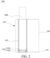
- an embodiment of the present invention provides an electronic atomizer 100, including a battery assembly (not shown) and a heating assembly 110.
- a solid aerosol-generation substrate 200 may be inserted into the heating assembly 110, and the heating assembly 110 can heat the aerosol-generation substrate 200 under an action of electrical energy of a battery, so as to generate aerosols for a user to inhale.
- the aerosol-generation substrate 200 is in a cylindrical shape.
- the method used by the conventional electronic atomizer for detecting whether an aerosol-generation substrate is inserted is relatively complex and has low reliability, which hinders the promotion and application of the electronic atomizer to some extent.
- the heating assembly 110 includes a main housing 120, which includes a heating cavity 147 with an opening at one end.
- the heating cavity 147 is configured to accommodate the aerosol-generation substrate 200.
- the electronic atomizer 100 further includes a detection unit (not shown). The detection unit is electrically connected to the heating assembly 110, and is configured to determine whether there is the aerosol-generation substrate 200 accommodated in a heating cylinder 140, thereby controlling an operating state of the electronic atomizer 100.
- the heating cavity 147 includes a first conductive region, a second conductive region, and an insulating region.
- the second conductive region is provided on a side of the first conductive region.
- the first conductive region and the second conductive region can respectively be used as a transceiver for performing capacitive sensing and a transceiver for performing resistance measurement, so as to receive and transmit a capacitive sensing signal and a resistance change signal.
- the insulating region is provided between the first conductive region and the second conductive region and is configured to electrically isolate the first conductive region from the second conductive region.
- the detection unit is configured to detect the capacitive sensing signal and the resistance signal between the first conductive region and the second conductive region, and to output an insertion signal according to the capacitive sensing signal and the resistance signal.
- the first conductive region When there is no aerosol-generation substrate 200 accommodated in the heating cavity 147, the first conductive region is electrically isolated from the second conductive region by the insulating region. Therefore, the first conductive region and the second conductive region cannot form an electrical signal loop. In this case, the capacitive sensing signal and the resistance signal between the first conductive region and the second conductive region are obtained by the detection unit, and are respectively marked as C1 and R1.
- the aerosol-generation substrate 200 improves electrical conductivity of the first conductive region and the second conductive region.
- An electrical connection is formed between the first conductive region and the second conductive region through the solid aerosol-generation substrate 200, thereby changing magnitude of the capacitive sensing signal and the resistance signal between the first conductive region and the second conductive region.
- the capacitive sensing signal and the resistance signal between the first conductive region and the second conductive region are obtained by the detection unit, and are respectively marked as C2 and R2.
- the detection unit obtains differences (that is, a difference between C1 and C2, and a difference between R1 and R2) between values measured before and after by filtering through an algorithm, then determines whether there is the aerosol-generation substrate 200 accommodated in the heating cavity 147 by determining sizes of the measurement differences and a preset calibration difference.
- the heating assembly 110 can accurately detect whether there is the aerosol-generation substrate 200 accommodated in the heating cavity 147 without a manual operation by a user, which is high in ease of use and reliability, and prevents the aerosol-generation substrate 200 from being excessively squeezed, thereby eliminating the risk of damaging the aerosol-generation substrate 200.
- a structure of the heating assembly 110 is simple, and therefore there is no need to add too many components such as an electromagnetic induction coil, thereby reducing the production cost and increasing the assembly efficiency.
- the detection unit is a capacitance detection chip or a resistance detection chip.
- the detection unit is usually in a standby state, and is woke up at regular intervals to perform detection. An interval time preferably ranges from 0.1 second to 1 second.
- the detection unit detects the existence of the aerosol-generation substrate 200, detection is performed repeatedly for many times. If the existence aerosol-generation substrate 200 is detected each time, it is determined that there is the aerosol-generation substrate 200 accommodated in the heating cavity 147, thus outputting the insertion signal to cause the heating assembly 110 to generate heat to heat the aerosol-generation substrate 200.
- the heating cavity 147 includes a first end and a second end that are arranged opposite to each other.
- the first end is an end of the heating cavity 147 having an opening end that is in communication with an external environment
- the second end is an end of the heating cavity 147 provided with a cavity bottom wall.
- the aerosol-generation substrate is inserted into the second end from the first end of the heating cavity 147.
- the first conductive region is provided on a side of the second conductive region facing the second end. That is, during insertion of the aerosol-generation substrate 200, the aerosol-generation substrate 200 first comes into contact with the first conductive region, and then it comes into contact with the second conductive region.
- a part of the aerosol-generation substrate 200 is in contact with the first conductive region, and the other part of the aerosol-generation substrate 200 is in contact with the second conductive region, so as to implement the electrical connection between the first conductive region and the second conductive region. Since the electrical connection between the first conductive region and the second conductive region can be implemented only when the aerosol-generation substrate 200 is simultaneously in contact with the first conductive region and the second conductive region, a range of a heating area of the aerosol-generation substrate 200 may be controlled by setting a position of the second conductive region, so as to implemented different heating requirements.
- the first conductive region is provided at the second end of the heating cavity 147, and the second conductive region is provided on a cavity side wall of the heating cavity 147.
- one end of the second conductive region is connected to the insulating region, and the other end of the second conductive region extends to the second end of the heating cavity 147 in a direction away from the insulating region. Since the first conductive region is provided at the second end of the heating cavity 147, when and only when the aerosol-generation substrate 200 is inserted into the bottom of the heating cavity 147 to be in contact with the first conductive region, the first conductive region can be electrically connected to the second conductive region through the solid aerosol-generation substrate 200.
- the aerosol-generation substrate 200 is heated when the aerosol-generation substrate 200 is not inserted in place, thereby preventing a position of a heating area from offsetting because the aerosol-generation substrate 200 is not completely inserted into the heating cavity 147. Therefore, the heating effect of the heating assembly 110 is ensured.
- the heating assembly 110 includes the heating cylinder 140 arranged in the main housing 120.
- the heating cylinder 140 has a substantially cylindrical shape to form the heating cavity 147.
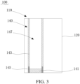
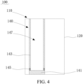
- the heating cylinder 140 includes a first structural member 141, a second structural member 143, and an insulating member 145.
- the first structural member 141 forms a part of the cavity bottom wall of the heating cavity 147, and at least a part of the first structural member 141 forms the first conductive region.
- the second structural member 143 forms a part of the cavity side wall of the heating cavity 147, and at least a part of the second structural member 143 forms the second conductive region.
- the insulating member 145 is arranged between the first structural member 141 and the second structural member 143, and the insulating member 145 forms the insulating region.
- the first structural member 141 has a solid cylindrical shape and is entirely made of a conductive material. An upper surface of the first structural member 141 forms a part of the cavity bottom wall of the heating cavity 147, and the first structural member 141 forms the first conductive region.
- the insulating member 145 has a hollow rotating body shape.
- the insulating member 145 which is entirely made of an insulating material, includes an insulating bottom wall 1452 and an insulating side wall 1454 formed by extending from the insulating bottom wall 1452 in the same direction.
- the insulating side wall 1454 surrounds the insulating bottom wall 1452 in a circumferential direction to form an insulating accommodating cavity.
- the insulating bottom wall 1452 is provided with a mounting hole in communication with the insulating accommodating cavity.
- the mounting hole and the insulating accommodating cavity are coaxially arranged, and an inner diameter of the mounting hole is less than an inner diameter of the insulating accommodating cavity.
- the first structural member 141 is accommodated in the mounting hole.
- An upper surface of the insulating bottom wall 1452 surrounds the upper surface of the first structural member 141 to form the other part of the cavity bottom wall.
- An inner surface of the insulating side wall 1454 forms a part of the cavity side wall of the heating cavity 147.
- the insulating member 145 forms the insulating region.
- the second structural member 143 has a hollow tubular shape and is entirely made of a conductive material. One end of the second structural member 143 is connected to the insulating side wall 1454, and the other end of the second structural member 143 extends vertically in a direction away from the first structural member 141, so as to form a hollow cylindrical structure and be in communication with the insulating accommodating cavity. In addition, an inner diameter of the second structural member 143 is the same as an inner diameter of the insulating member 145. An inner surface of the second structural member 143 forms the other part of the cavity bottom wall of the heating cavity 147, and the second structural member 143 forms the second conductive region.
- the insulating member 145, the first structural member 141, and the second structural member 143 jointly form the heating cavity 147 with an opening at one end.
- the insulating bottom wall 1452 and the first structural member 141 jointly form the cavity bottom wall of the heating cavity 147, and the insulating side wall 1454 and the second structural member 143 jointly from the cavity side wall of the heating cavity 147.
- One end of the aerosol-generation substrate 200 passes through the second structural member 143 and abuts against the first structural member 141.
- the second structural member 143 is wrapped on an outer circular surface of the aerosol-generation substrate 200, so that the aerosol-generation substrate 200 may serve to increase a resistance value and a capacitance value between the first structural member 141 and the second structural member 143.
- a size of the first structural member 141 and a size of the mounting hole matching the first structural member may be adjusted as required, so as to further adjust a minimum gap between the first structural member 141 and the second structural member 143, thereby avoiding a mistaken triggering caused by an excessive short distance between the first structural member 141 and the second structural member 143.
- the insulating member 145 has a tubular shape with openings at two ends, and inner diameters of the insulating member 145 are equal everywhere.
- the first structural member 141 is accommodated in the insulating member 145.
- an axial length of the insulating member 145 is greater than an axial length of the insulating member 145, and the insulating member 145 protrudes from an end of the first structural member 141 facing the opening end of the heating cavity 147.
- the insulating member 145 is provided between the first structural member 141 and the second structural member 143.
- the insulating member 145 is in a tubular shape with the openings at two ends. The first structural member 141 and the second structural member 143 abut against the two opposite ends of the insulating member 145, respectively.
- both the first conductive region and the second conductive region are formed by a conductive film formed in the main housing 120, and in this case, the first structural member 141 and the second structural member 143 can be omitted.
- the electronic atomizer 100 further includes a vibration unit (not shown).
- the vibration unit vibrates, so as to remind the user that the aerosol-generation substrate 200 has been inserted into a correct position, thereby preventing the user from continuing to exert a force to cause the aerosol-generation substrate 200 to be deformed and damaged after the aerosol-generation substrate 200 is in contact with the first structural member 141.
- the heating assembly 110 and the electronic atomizer 100 performs insertion detection by using the principle that the aerosol-generation substrate 200 can increase the electrical conductivity between the first conductive region and the second conductive region.
- the heating assembly 110 and the electronic atomizer 100 have simple structures and relatively high reliability, thus causing no damage to the aerosol-generation substrate 200.
- the heating assembly 110 can accurately detects whether the aerosol-generation substrate 200 is inserted into the bottom portion of the heating cavity 147, and provides a feedback to the user through vibration, thereby preventing the heating effect from being affected because the heating position is offset, and preventing the aerosol-generation substrate 200 from being deformed due to an excessive force exerted by the user, and ensuring good inhaling taste.
Landscapes
- Health & Medical Sciences (AREA)
- Engineering & Computer Science (AREA)
- Public Health (AREA)
- Veterinary Medicine (AREA)
- Biomedical Technology (AREA)
- Heart & Thoracic Surgery (AREA)
- Hematology (AREA)
- Life Sciences & Earth Sciences (AREA)
- Animal Behavior & Ethology (AREA)
- General Health & Medical Sciences (AREA)
- Human Computer Interaction (AREA)
- Anesthesiology (AREA)
- Bioinformatics & Cheminformatics (AREA)
- Pulmonology (AREA)
- Resistance Heating (AREA)
- Physics & Mathematics (AREA)
- General Physics & Mathematics (AREA)
- Investigating Or Analyzing Materials By The Use Of Electric Means (AREA)
- Investigating Or Analyzing Materials By The Use Of Fluid Adsorption Or Reactions (AREA)
- Infusion, Injection, And Reservoir Apparatuses (AREA)
- Catching Or Destruction (AREA)
Applications Claiming Priority (1)
| Application Number | Priority Date | Filing Date | Title |
|---|---|---|---|
| CN202123320550.6U CN217242720U (zh) | 2021-12-27 | 2021-12-27 | 加热组件及电子雾化器 |
Publications (2)
| Publication Number | Publication Date |
|---|---|
| EP4201237A1 true EP4201237A1 (de) | 2023-06-28 |
| EP4201237B1 EP4201237B1 (de) | 2026-03-25 |
Family
ID=82891581
Family Applications (1)
| Application Number | Title | Priority Date | Filing Date |
|---|---|---|---|
| EP22213862.0A Active EP4201237B1 (de) | 2021-12-27 | 2022-12-15 | Heizanordnung und elektronischer zerstäuber |
Country Status (5)
| Country | Link |
|---|---|
| US (1) | US12551638B2 (de) |
| EP (1) | EP4201237B1 (de) |
| JP (1) | JP7507837B2 (de) |
| KR (1) | KR102818816B1 (de) |
| CN (1) | CN217242720U (de) |
Families Citing this family (2)
| Publication number | Priority date | Publication date | Assignee | Title |
|---|---|---|---|---|
| CN217242720U (zh) * | 2021-12-27 | 2022-08-23 | 深圳麦克韦尔科技有限公司 | 加热组件及电子雾化器 |
| CN115568636A (zh) * | 2022-09-29 | 2023-01-06 | 深圳麦克韦尔科技有限公司 | 雾化组件、电子雾化装置以及检测方法 |
Citations (4)
| Publication number | Priority date | Publication date | Assignee | Title |
|---|---|---|---|---|
| EP3280280A1 (de) * | 2015-04-07 | 2018-02-14 | Philip Morris Products S.a.s. | Beutel mit aerosolerzeugendem substrat, verfahren zur herstellung davon und aerosolerzeugungsvorrichtung zur verwendung mit beutel |
| WO2020201295A1 (en) * | 2019-04-02 | 2020-10-08 | Philip Morris Products S.A. | Aerosol-generating device with article position detector |
| US20210100289A1 (en) * | 2018-05-10 | 2021-04-08 | Jt International S.A. | Consumable Cartridge For An Aerosol Generation Device |
| WO2021069526A1 (en) * | 2019-10-09 | 2021-04-15 | Jt International Sa | Aerosol generation device |
Family Cites Families (20)
| Publication number | Priority date | Publication date | Assignee | Title |
|---|---|---|---|---|
| EP2338361A1 (de) * | 2009-12-23 | 2011-06-29 | Philip Morris Products S.A. | Längliche Heizung für ein elektrisch erwärmtes Aerosol-Erzeugungssystem |
| US9597466B2 (en) * | 2014-03-12 | 2017-03-21 | R. J. Reynolds Tobacco Company | Aerosol delivery system and related method, apparatus, and computer program product for providing control information to an aerosol delivery device via a cartridge |
| US11696604B2 (en) * | 2014-03-13 | 2023-07-11 | Rai Strategic Holdings, Inc. | Aerosol delivery device and related method and computer program product for controlling an aerosol delivery device based on input characteristics |
| US20170119052A1 (en) * | 2015-10-30 | 2017-05-04 | R.J. Reynolds Tobacco Company | Application specific integrated circuit (asic) for an aerosol delivery device |
| US11160936B2 (en) * | 2017-06-23 | 2021-11-02 | Altria Client Services Llc | Non-combustible vaping device |
| CN108041687B (zh) * | 2017-12-22 | 2020-11-27 | 安徽中烟工业有限责任公司 | 具有低温燃烧热源的气雾产生物品 |
| CN108378427A (zh) | 2018-04-26 | 2018-08-10 | 万利龙 | 混合式电子烟 |
| CN110403241B (zh) | 2018-04-28 | 2021-02-23 | 深圳御烟实业有限公司 | 气溶胶生成装置和系统 |
| WO2019234143A1 (en) * | 2018-06-07 | 2019-12-12 | Philip Morris Products S.A. | Electrical heating assembly for heating an aerosol-forming substrate |
| EP3806672B1 (de) * | 2018-06-14 | 2025-12-31 | Philip Morris Products S.A. | Aerosolerzeugungsvorrichtung mit heizbeschichtung |
| KR102392126B1 (ko) * | 2019-08-02 | 2022-04-28 | 주식회사 케이티앤지 | 가열 조립체, 이를 포함하는 에어로졸 발생 장치 및 에어로졸 발생 시스템 |
| CN111109684A (zh) * | 2020-01-16 | 2020-05-08 | 深圳麦克韦尔科技有限公司 | 气雾产生装置及其气雾产生基质 |
| US12433345B2 (en) | 2020-03-10 | 2025-10-07 | Jt International Sa | Aerosol generation device battery monitoring |
| JP7260712B2 (ja) | 2020-03-18 | 2023-04-18 | 日本たばこ産業株式会社 | 制御装置、制御方法、及びプログラム |
| KR102509092B1 (ko) * | 2020-05-20 | 2023-03-10 | 주식회사 케이티앤지 | 히터 조립체 및 그의 제조 방법 |
| CN213604399U (zh) * | 2020-09-22 | 2021-07-06 | 深圳市合元科技有限公司 | 气溶胶生成装置以及红外加热器 |
| CN112315031A (zh) | 2020-11-20 | 2021-02-05 | 河南中烟工业有限责任公司 | 基于极间电容介电常数变化的烟支检测方法 |
| CN113768196B (zh) * | 2021-08-26 | 2024-08-02 | 深圳麦时科技有限公司 | 一种电子雾化装置及其发热组件 |
| CN217242720U (zh) * | 2021-12-27 | 2022-08-23 | 深圳麦克韦尔科技有限公司 | 加热组件及电子雾化器 |
| WO2024002967A1 (en) * | 2022-06-27 | 2024-01-04 | Jt International Sa | Aerosol generation device |
-
2021
- 2021-12-27 CN CN202123320550.6U patent/CN217242720U/zh active Active
-
2022
- 2022-11-14 KR KR1020220151627A patent/KR102818816B1/ko active Active
- 2022-11-29 JP JP2022189978A patent/JP7507837B2/ja active Active
- 2022-12-14 US US18/081,241 patent/US12551638B2/en active Active
- 2022-12-15 EP EP22213862.0A patent/EP4201237B1/de active Active
Patent Citations (4)
| Publication number | Priority date | Publication date | Assignee | Title |
|---|---|---|---|---|
| EP3280280A1 (de) * | 2015-04-07 | 2018-02-14 | Philip Morris Products S.a.s. | Beutel mit aerosolerzeugendem substrat, verfahren zur herstellung davon und aerosolerzeugungsvorrichtung zur verwendung mit beutel |
| US20210100289A1 (en) * | 2018-05-10 | 2021-04-08 | Jt International S.A. | Consumable Cartridge For An Aerosol Generation Device |
| WO2020201295A1 (en) * | 2019-04-02 | 2020-10-08 | Philip Morris Products S.A. | Aerosol-generating device with article position detector |
| WO2021069526A1 (en) * | 2019-10-09 | 2021-04-15 | Jt International Sa | Aerosol generation device |
Also Published As
| Publication number | Publication date |
|---|---|
| KR20230099630A (ko) | 2023-07-04 |
| JP7507837B2 (ja) | 2024-06-28 |
| KR102818816B1 (ko) | 2025-06-11 |
| US12551638B2 (en) | 2026-02-17 |
| US20230201491A1 (en) | 2023-06-29 |
| CN217242720U (zh) | 2022-08-23 |
| JP2023097370A (ja) | 2023-07-07 |
| EP4201237B1 (de) | 2026-03-25 |
Similar Documents
| Publication | Publication Date | Title |
|---|---|---|
| EP4201237A1 (de) | Heizanordnung und elektronischer zerstäuber | |
| CN113758597B (zh) | 温度探针和烤箱组件 | |
| CN106455707B (zh) | 用于加热可吸用材料的设备和可吸用材料制品 | |
| JP4222830B2 (ja) | 温度プレートとばねとを備えた圧力トランスデュサー | |
| EP3387923B1 (de) | Elektronische zigarettenvorrichtung und verfahren zur berechnung der anzahl der züge | |
| US20060144155A1 (en) | Pressure flow sensor systems and pressure flow sensors for use therein | |
| JP4316007B2 (ja) | ピラニ真空計 | |
| JP2021534742A5 (de) | ||
| CN216160043U (zh) | 温度探针及烤箱组件 | |
| US12446625B2 (en) | Vapor generation device and susceptor | |
| CN113068865A (zh) | 发热组件和电加热烟具 | |
| CN210642460U (zh) | 发热组件以及电子烟 | |
| CN219781623U (zh) | 测温装置及气溶胶产生设备 | |
| CN113925231A (zh) | 气溶胶产生装置 | |
| US20240237746A1 (en) | Electronic vaporization device and vaporizer thereof | |
| CN111855001A (zh) | 一种电缆中间接头温度测量装置 | |
| CN110702301A (zh) | 一种薄膜真空计 | |
| WO2025213592A1 (zh) | 雾化器、雾化装置及控制方法和装置、控制器、存储介质 | |
| CN217466073U (zh) | 一种风压传感器 | |
| CN116268636B (zh) | 测温装置及气溶胶产生设备 | |
| CN216568383U (zh) | 一种加热组件及气溶胶产生装置 | |
| CN212722700U (zh) | 凝露检测仪 | |
| CN108732408A (zh) | 一种基于磁化膜的应变式电流传感器 | |
| CN222211988U (zh) | 一种自发电感温探测器 | |
| CN219908190U (zh) | 具有烘干功能的衣物处理设备 |
Legal Events
| Date | Code | Title | Description |
|---|---|---|---|
| PUAI | Public reference made under article 153(3) epc to a published international application that has entered the european phase |
Free format text: ORIGINAL CODE: 0009012 |
|
| STAA | Information on the status of an ep patent application or granted ep patent |
Free format text: STATUS: THE APPLICATION HAS BEEN PUBLISHED |
|
| AK | Designated contracting states |
Kind code of ref document: A1 Designated state(s): AL AT BE BG CH CY CZ DE DK EE ES FI FR GB GR HR HU IE IS IT LI LT LU LV MC ME MK MT NL NO PL PT RO RS SE SI SK SM TR |
|
| STAA | Information on the status of an ep patent application or granted ep patent |
Free format text: STATUS: REQUEST FOR EXAMINATION WAS MADE |
|
| 17P | Request for examination filed |
Effective date: 20231013 |
|
| RBV | Designated contracting states (corrected) |
Designated state(s): AL AT BE BG CH CY CZ DE DK EE ES FI FR GB GR HR HU IE IS IT LI LT LU LV MC ME MK MT NL NO PL PT RO RS SE SI SK SM TR |
|
| RAP3 | Party data changed (applicant data changed or rights of an application transferred) |
Owner name: SHENZHEN SMOORE TECHNOLOGY LIMITED |
|
| RAP3 | Party data changed (applicant data changed or rights of an application transferred) |
Owner name: SHENZHEN SMOORE TECHNOLOGY LIMITED |
|
| GRAP | Despatch of communication of intention to grant a patent |
Free format text: ORIGINAL CODE: EPIDOSNIGR1 |
|
| STAA | Information on the status of an ep patent application or granted ep patent |
Free format text: STATUS: GRANT OF PATENT IS INTENDED |
|
| INTG | Intention to grant announced |
Effective date: 20260108 |
|
| GRAS | Grant fee paid |
Free format text: ORIGINAL CODE: EPIDOSNIGR3 |
|
| GRAA | (expected) grant |
Free format text: ORIGINAL CODE: 0009210 |
|
| STAA | Information on the status of an ep patent application or granted ep patent |
Free format text: STATUS: THE PATENT HAS BEEN GRANTED |
|
| P01 | Opt-out of the competence of the unified patent court (upc) registered |
Free format text: CASE NUMBER: UPC_APP_0002738_4201237/2026 Effective date: 20260126 |
|
| AK | Designated contracting states |
Kind code of ref document: B1 Designated state(s): AL AT BE BG CH CY CZ DE DK EE ES FI FR GB GR HR HU IE IS IT LI LT LU LV MC ME MK MT NL NO PL PT RO RS SE SI SK SM TR |
|
| REG | Reference to a national code |
Ref country code: CH Ref legal event code: F10 Free format text: ST27 STATUS EVENT CODE: U-0-0-F10-F00 (AS PROVIDED BY THE NATIONAL OFFICE) Effective date: 20260325 Ref country code: GB Ref legal event code: FG4D |
|
| REG | Reference to a national code |
Ref country code: DE Ref legal event code: R096 Ref document number: 602022032911 Country of ref document: DE |
|
| REG | Reference to a national code |
Ref country code: IE Ref legal event code: FG4D |