EP4201166B1 - Outil de travail du sol - Google Patents
Outil de travail du sol Download PDFInfo
- Publication number
- EP4201166B1 EP4201166B1 EP22214628.4A EP22214628A EP4201166B1 EP 4201166 B1 EP4201166 B1 EP 4201166B1 EP 22214628 A EP22214628 A EP 22214628A EP 4201166 B1 EP4201166 B1 EP 4201166B1
- Authority
- EP
- European Patent Office
- Prior art keywords
- soil
- unit
- reconsolidation
- soil cultivation
- cultivation
- Prior art date
- Legal status (The legal status is an assumption and is not a legal conclusion. Google has not performed a legal analysis and makes no representation as to the accuracy of the status listed.)
- Active
Links
Images

Classifications
-
- A—HUMAN NECESSITIES
- A01—AGRICULTURE; FORESTRY; ANIMAL HUSBANDRY; HUNTING; TRAPPING; FISHING
- A01B—SOIL WORKING IN AGRICULTURE OR FORESTRY; PARTS, DETAILS, OR ACCESSORIES OF AGRICULTURAL MACHINES OR IMPLEMENTS, IN GENERAL
- A01B49/00—Combined machines
- A01B49/02—Combined machines with two or more soil-working tools of different kind
- A01B49/027—Combined machines with two or more soil-working tools of different kind with a rotating, soil working support element, e.g. a roller
-
- A—HUMAN NECESSITIES
- A01—AGRICULTURE; FORESTRY; ANIMAL HUSBANDRY; HUNTING; TRAPPING; FISHING
- A01B—SOIL WORKING IN AGRICULTURE OR FORESTRY; PARTS, DETAILS, OR ACCESSORIES OF AGRICULTURAL MACHINES OR IMPLEMENTS, IN GENERAL
- A01B17/00—Ploughs with special additional arrangements, e.g. means for putting manure under the soil, clod-crushers
Definitions
- the present invention relates to a soil tillage device for tilling a soil with soil tillage tools along a working direction, which is designed to carry out a left-turning tillage of the soil in a first working position and a right-turning tillage of the soil in a second working position, wherein a soil post-processing unit is attached to the soil tillage device.
- Soil cultivation equipment is known in the art that is used to cultivate soil, such as a field, using tillage tools to improve soil quality and prepare the soil for subsequent cultivation or sowing.
- Typical tillage equipment of this type includes ploughs, with attached plough bodies that turn the soil over as they travel along a working direction. Turning is sometimes achieved by a share of the plough body detaching a piece of soil from a furrow sole, guiding it onto a moldboard, rotating it around a longitudinal axis, and then depositing it to one side of the detaching piece.
- right-turning tillage of this type the piece of soil is deposited on the subsoil to the right of its original position, as seen in the working direction.
- the soil beam is rotated clockwise to the right, as viewed in the working direction.
- the soil beam is placed to the left of its original position on the ground, as viewed in the working direction, and is rotated counterclockwise to the left, as viewed in the working direction.
- the working direction is the direction in which the tillage implement is moved to cultivate the soil.
- a soil tillage implement that tills a soil by turning left or right within the meaning of the present invention is particularly exposed to a lateral force and can, for example, also be a disc harrow whose discs are inclined to a working direction and cut and mix the soil. Depending on the inclination of the discs of the disc harrow with respect to the working direction, parts of the tilled soil are displaced to the right or left, thus resulting in a left- or right-sided force.
- soil post-processing unit behind the soil tillage implement to enable, for example, reconsolidation, leveling, or seeding in the same operation.
- soil post-processing units include soil rollers.
- Soil cultivation tools such as the aforementioned plough bodies or discs, which cause one of the described or similar displacements of the soil, always exert a force on the soil that is directed transversely to the working direction.
- An opposing force acts from the ground on the soil cultivation implement, which manifests itself as a lateral pull to the right when the soil cultivation implement is moved along the working direction in a left-turning working position, or as a lateral pull to the left when the soil cultivation implement is moved in the right-turning working position. If you want to prevent the If the tillage implement drifts from the desired track while cultivating the soil, these lateral pull forces must be compensated by the tillage implement itself or by the tractor that pulls or pushes the tillage implement.
- ploughs so-called reversible ploughs have recently become popular. These feature both a left-turning and a right-turning working position, between which the plough can be switched.
- the direction of the lateral pull depends on the respective working position. Consequently, any measure taken to absorb lateral forces must be equally suitable for balancing forces acting to the left as well as forces acting to the right.
- parts of the soil are deposited on the left or right side outside the engagement track of the tillage tools, depending on the working position.
- a soil tillage implement which has both a left-turning and a right-turning working position, with a soil post-processing unit attached thereto, which can be operated without lateral pull, without entailing the above disadvantages of unwanted soil compaction, wear, uneconomical operation of a tractor used to pull the soil tillage implement or insufficient coverage of a soil tillage track between the soil tillage implement and the soil post-processing unit.
- a soil tillage device is provided with a soil tillage unit for tilling a soil with soil tillage tools along a working direction, which is designed to carry out left-turning tillage of the soil in a first working position and right-turning tillage of the soil in a second working position, wherein a soil post-processing unit is attached to the soil tillage unit by means of a pivotable adjustment mechanism such that the soil post-processing unit is arranged behind the soil tillage unit in the working direction, wherein the adjustment mechanism enables the soil post-processing unit to be laterally displaced with respect to the working direction and to be adjusted to both sides at an angle of adjustment relative to the working direction in order to exert an adjustable lateral pulling force on the soil tillage device through interaction with the soil.
- the interaction with the ground includes in particular sliding friction, rolling friction and a combination thereof, but also any other type of mechanical force absorption.
- the lateral pull generated during both left-turning and right-turning tillage can be compensated by the lateral pull exerted by the tillage unit.
- This facilitates the straight running of the combination of tillage unit and tillage unit.
- the soil cultivation unit and additional post-processing, such as cultivation or reconsolidation, are carried out by the soil cultivation device in a single operation. Since the soil cultivation unit can be moved laterally in relation to the working direction, the track it travels over can overlap with a soil cultivation track of the soil cultivation unit. Additional mechanisms for absorbing lateral forces are no longer necessary or are only necessary to a limited extent.
- the present invention according to which the soil cultivation unit can be moved both laterally and its angle can be adjusted, enables particularly efficient implementation of both lateral pull compensation and adaptation to the working direction, i.e. left and right, which is of great value in particular for ploughs, disc harrows and similar soil cultivation units.
- the soil preparation unit is attached to the soil cultivation unit means that there is a direct or indirect connection between the two units.
- this also includes the soil preparation unit and the soil cultivation unit being attached together and in a fixed relative arrangement to a device.
- the soil preparation unit can be coupled to the tractor directly or via the soil cultivation unit.
- the soil preparation unit then exerts an adjustable lateral traction force on the soil cultivation device indirectly via the tractor.
- the attachment of the soil preparation unit to the soil cultivation unit as described below equivalent to a corresponding attachment to a tractor or the like.
- the adjusting mechanism has a first handlebar with a first handlebar length and a second handlebar with a second handlebar length, which connect the soil preparation unit and the soil preparation unit to one another, wherein the first handlebar extends between a first soil preparation unit attachment on the soil preparation unit and a first soil preparation unit attachment on the soil preparation unit and the second handlebar extends between a second soil preparation unit attachment on the soil preparation unit and a second soil preparation unit attachment on the soil preparation unit, wherein in a first case the first handlebar and the second handlebar diverge in the working direction, or in a second case the first handlebar and the second handlebar run parallel to one another and the first handlebar length and/or the second handlebar length is adjustable.
- the adjustment mechanism using steering rods it is particularly easy not only to adjust the soil preparation unit relative to a working direction, but also to offset it laterally to the left or right in relation to the soil cultivation implement in the working direction.
- the soil cultivation tools of the soil cultivation implement can span a total soil cultivation width with which they create an engagement track, but the soil preparation track can extend beyond this engagement track to the left or right depending on the position of the adjustment mechanism. This ensures that lateral pull compensation with a position compensation that enables efficient and precise cultivation of the soil.
- a steering trapezoid is formed by the first steering rod, a connecting line between the soil cultivation unit attachments, the second steering rod and a connecting line between the soil post-processing unit attachments.
- a neutral position of the adjustment mechanism i.e. a position in which the angle of attack relative to the working direction is approximately zero
- a soil post-processing unit axis can run perpendicular to the working direction and parallel to a soil cultivation unit axis.
- the preferred steering trapeze of the adjustment mechanism ensures that the instantaneous centre of gravity of the swivel movement of the soil preparation unit guided by the steering rods is always located behind the soil preparation unit in the working direction.
- the angle of attack is adjustable by the differently adjustable handlebar lengths.
- the first ground finishing unit attachment and the second ground finishing unit attachment are arranged on the ground finishing unit in the working direction such that the ground finishing unit is located for the most part in the working direction in front of or behind the first ground finishing unit attachment and the second ground finishing unit attachment.
- the lateral offset of the tillage unit is determined in particular by the length of the steering rods. If the tillage unit attachments are arranged as far back as possible on the tillage unit, i.e. the tillage unit is located mostly in front of the first and second tillage unit attachments in the working direction, the tillage unit and the tillage unit can be moved closer together and the free space between them can be minimized. At the same time, however, a long length of the steering rods is ensured in order to ensure the desired lateral offset. In this advantageous embodiment, the length of the tillage implement is therefore shorter, and the tillage implement is thereby easier to lift and turn. In contrast, if the tillage unit is located mostly in the working direction behind the first and second tillage unit attachments, a higher strength of the overall arrangement can be expected, which is an advantage especially when the tillage unit has to absorb relatively large forces.
- the soil cultivation unit is a plough, more preferably a reversible plough, particularly preferably a full-turn plough, most preferably a full-turn parallel plough, wherein the soil cultivation tools are plough bodies.
- the soil preparation unit is not only adjustable but also laterally movable.
- the soil post-processing unit is preferably designed to effect reconsolidation, leveling or sowing and is in particular a packer roller, rod roller, knife roller, depth control roller, rotary harrow, knife bar, tine bar, leveling bar or seed bar.
- the soil post-processing unit not only efficiently compensates for lateral pull, but also serves to particularly efficiently reconsolidate and cultivate the soil.
- a repeat pass over the soil for reconsolidation, leveling, or sowing can then be eliminated, allowing, for example, the cultivation of arable land to be carried out much more efficiently.
- a working depth of the soil cultivation tools is adjustable, preferably relative to the soil post-treatment unit.
- the working depth of the tillage tools is adjustable, it can be adapted to different soil conditions and the desired tillage pattern.
- the working depth of the tillage tools and their resulting varying interaction with the soil can also influence the strength of the lateral pull caused by the tillage tools.
- the deeper the soil is tilled i.e., the deeper the working depth of the tillage tools is set, the greater the lateral pull of the tillage unit.
- the lateral traction force exerted by the soil preparation unit is This becomes greater the more the soil preparation unit interacts with the soil. If, in a preferred embodiment, the working depth is adjustable relative to the soil preparation unit, this means that the lateral pull caused by the soil preparation tools and the compensating lateral pull caused by the soil preparation unit can be adjusted independently of one another.
- the adjustment mechanism has a height guide, in particular a parallelogram height guide, for adjusting and/or changing the working depth of the soil cultivation tools relative to the soil preparation unit, regardless of the set angle of attack. This makes it possible, in particular, to adjust the force applied to the soil by the soil preparation unit and thus a possible interaction with the soil.
- the soil tillage implement has a first end stop and a second end stop for the adjustment mechanism, by means of which the respective angle of attack can be preset to the left and right with respect to the working direction, wherein the angle of attack can be switched between right and left in particular by switching the adjustment mechanism between the first end stop and the second end stop.
- the angle of attack relative to the working direction has a significant influence on the degree of lateral traction exerted by the soil preparation unit. Together with the interaction of the soil preparation unit with the soil, particularly slippage, sliding friction, etc., it determines the degree of lateral traction. Because the adjustment mechanism has two In an advantageous embodiment, the degree of lateral traction can be preset to the left and right by adjusting the setting mechanism. In particular, if the setting angle can be adjusted between the two end stops by adjusting the setting mechanism, the lateral traction applied by the soil preparation unit can be adjusted efficiently and very precisely when switching between the right-turning and left-turning working positions of the soil tillage implement by moving the setting mechanism to the position of the respective end stop.
- the angle of attack is variably adjustable, in particular in that a first attachment distance between the first soil tillage unit attachment and the second soil tillage unit attachment is variably adjustable, in particular in that a second attachment distance between the first soil post-processing unit attachment and the second soil post-processing unit attachment is variably adjustable and/or in particular in that the first handlebar length and/or the second handlebar length is variably adjustable.
- the lateral traction can be variably adjusted.
- the distance between the soil cultivation unit attachments can be adjusted. The smaller this distance, the less deflection of the steering rods from their neutral positions is required to set a specific angle of attack.
- the distance between the soil preparation unit attachments can be adjusted. The smaller this distance, the less deflection of the steering rods from their neutral positions is required to to set a specific angle of attack.
- the first and/or second steering rod length can be changed. The longer the steering rods, the less effect a deflection of the steering rods from their neutral position has on the angle of attack.
- a steering trapezoid spanned by the steering rods and the mounting distances approaches a parallelogram, so that a deflection of the steering rods does result in a lateral displacement of the soil preparation unit in relation to the working direction, but this lateral displacement is only accompanied by a smaller angle of attack. If one steering rod is shortened or lengthened in relation to the other steering rod, the angle of attack can also be influenced.
- the angle of attack is variably adjustable mechanically by means of fixed locking positions, mechanically by means of spring preload, by means of a servo motor by means of control by an operator and/or hydraulically by means of automatic control.
- the attachment points of the steering rods on the soil cultivation unit and/or on the soil post-processing unit can be adjustable via a hole pattern.
- a steering rod to comprise two or more rods that are movable relative to one another, of which at least one rod has a hole pattern and the other rod at least one hole, wherein the relative position of the rods is held by a bolt that engages in the hole of one rod and one of the holes in the hole pattern of the other rod.
- Other similar mechanisms can be used to adjust the positions of the handlebar attachment points or to adjust the length of the handlebars.
- a spring can be used to specify the attachment distances of the handlebars.
- the adjustability of the angle of attack is then achieved by increasing or decreasing the tension of the spring.
- an operator can adjust the angle of attack using a servomotor as an alternative or in addition to the mechanical adjustment. For example, if the tillage implement is being pulled by a tractor and the tractor driver notices that the tillage implement is exerting lateral pull on the tractor, he can readjust the angle of attack while driving by actuating a control for the servomotor, without having to interrupt work.
- the angle of attack can be controlled fully automatically by hydraulics.
- the angle of attack can be fully automatically adjusted and/or continuously adjusted as needed. This enables particularly economical operation of the soil tillage implement.
- the adjustment mechanism is designed to enable the soil processing unit to be adjusted via a forced drive or a sequential circuit due to a changeover of the soil tillage unit between the first working position and the second working position.
- switching the working position of the soil tillage unit between right-turning and left-turning cultivation of the soil triggers a corresponding adjustment and displacement of the soil post-cultivation unit.
- the soil post-cultivation unit can be automatically adjusted and displaced to the right. This process can advantageously occur essentially simultaneously with the changeover process.
- the soil tillage device can be folded from at least one of the working positions into a transport position in which the soil post-processing unit extends mainly vertically and in which it has a transport height.
- extending mainly vertically means that the extension of the soil refining unit is greater in the vertical direction than in the horizontal direction.
- the tillage unit extends vertically in the transport position of the tillage implement, it is possible to ensure a transport width of the tillage implement that does not exceed the permissible road transport width, even for a tillage unit whose working width exceeds the permissible road transport width.
- the preferred design of the adjustment mechanism allows the transport position to be adopted in such a way that not only the permissible road transport width is maintained, but also that the tillage implement does not become longer than necessary.
- the maximum permitted width of a vehicle is 3 m in large parts of Europe.
- the width of the soil tillage implement in the transport position should preferably be greater than the maximum permitted road transport width, in particular 3 m.
- the adjustment mechanism is designed to optionally adjust the vertical position of the soil preparation unit using a spring mechanism, in particular to ensure that a permissible road transport height is not exceeded in the transport position.
- the maximum permissible road transport height in large parts of Europe is 4 m.
- the adjustment mechanism is designed to adjust the vertical position of the soil preparation unit such that the transport height is at most the maximum permissible road transport height, in particular 4 m.
- the soil tillage unit of the soil tillage implement which has steering rods, supports the soil tillage tools on at least three transverse frames that extend to a working width.
- An adjustment mechanism is provided for at least two of the transverse frames, by means of which a soil post-processing unit is attached to the respective transverse frame and which each has the first steering rod and the second steering rod.
- a soil tillage unit of a corresponding width would require, on the one hand, an adjustment mechanism capable of moving such a large soil tillage unit, and, on the other hand, at a given angle of adjustment, the adjusted soil tillage unit would cover the length of the It is therefore advantageous to provide separate soil preparation units for at least the two outer cross frames, each with its own adjustment mechanism and together complementing the working width.
- the two outer cross frames of the soil tillage unit can then preferably be brought into a transport position, in which the cross frames and their associated soil post-processing units then extend essentially vertically.
- both a wide working width and a narrow transport width can be ensured.
- the soil post-processing unit further comprises a guide tool, in particular a disc coulter and/or a system, which can preferably be brought into interaction with the soil in order to influence the lateral traction force, i.e. to increase or decrease it.
- a guide tool in particular a disc coulter and/or a system, which can preferably be brought into interaction with the soil in order to influence the lateral traction force, i.e. to increase or decrease it.
- increased force can be applied by additional guide tools.
- these additional guide tools are not permanently in interaction with the soil, but can be used only when needed.
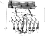
- Fig. 1 shows a plan view of a soil tillage implement 1 with a soil tillage unit 10, namely a full-turn parallel plough, with a soil tillage implement frame 60, to which a first transverse frame 11 and a second transverse frame 12 are each rotatably mounted via a turning axis.
- the transverse frames 11, 12 can be rotated separately, independently of one another, about their turning axis essentially by 180°. In a first working position, the transverse frames 11, 12 thus extend essentially transversely to a working direction A of the soil tillage unit 10 and essentially parallel to the soil to be tilled, which is parallel to the drawing plane of the Fig. 1 below the soil tillage implement 1.
- the cross frames 11, 12 are rotated by 180° compared to the first working position.
- the cross frames 11, 12 carry plough bodies as examples of soil cultivation tools 13.
- the plough bodies include both left-turning and right-turning plough bodies, and one left-turning and a right-turning plough body form a plough body pair.
- the working position of the soil tillage unit 10 shown is the left-turning working position, i.e.
- a soil beam picked up by a plough body is deposited on the ground further to the left of its original position, as seen in the working direction A.
- the leftmost plough body actually deposits its soil beam outside the working width of the soil tillage unit 10 in a left-hand side area B.
- This interaction of the plough body with the soil which leads to a movement of the soil beam to the left, causes a lateral pull of the soil tillage unit 10 to the right in the working direction A.
- the soil tillage implement 1 also has a hitch 30, which is connected to the soil tillage implement frame 60.
- the hitch 30 extends in a central area from the soil tillage implement frame 60 to the rear.
- the hitch 30 projects over and spans the plough bodies like a bridge.
- Fig. 1 In the plan view shown, the hitch 30 appears substantially T-shaped, with a first crossbeam 33 and a second crossbeam 34, or a single continuous crossbeam, extending on either side of a longitudinal member 35 of the hitch 30 behind the plough bodies transversely to the working direction A, i.e., parallel to the soil tillage implement frame 60, each to a free end.
- a soil tillage unit attachment 31 is located at the free end of the first crossbeam 33, and a soil tillage unit attachment 32 is located at the free end of the second crossbeam 34.
- the soil preparation unit 20 is designed as a packer roller. This is located behind the plough bodies. During soil preparation, the packer roller rotates about a rotation axis R. Soil preparation unit attachments 21 and 22 are located on a transverse frame 23 of the packer roller, which runs essentially parallel to the rotation axis R.
- the packer roller is set at a left angle of attack ⁇ 1 relative to the working direction A by means of an adjustment mechanism 40.
- the rotation axis R is therefore not perpendicular to the working direction A.
- the adjustment mechanism 40 has a first steering rod 41 and a second steering rod 42, both of which are the same length.
- One end of the steering rod 41 is pivotally connected to the first crossbeam 33 by means of the soil tillage unit attachment 31, while the other end of the steering rod 41 is pivotally connected to the packer roller by means of the soil preparation unit attachment 21.
- One end of the steering rod 42 is pivotally connected to the first crossbeam 34 by means of the soil tillage unit attachment 32, while the other end of the steering rod 42 is pivotally connected to the packer roller by means of the soil preparation unit attachment 22.
- the packer roller i.e., the soil preparation unit 20
- the full-turn parallel plough i.e., the soil preparation unit 10
- the two steering rods 41, 42 are located behind the plough bodies, i.e., the soil preparation tools 13.
- the design of the adjustment mechanism 40 by means of two steering rods 41, 42 makes it possible to adjust the packer roller and at the same time to be offset laterally so that one side of the packer roller projects beyond the plough bodies to the left in the left side area B, i.e. projects laterally beyond the working width of the soil cultivation tools 13.
- the packer roller is therefore not arranged in alignment with the soil cultivation unit 10. This ensures that a soil log worked by the leftmost plough body and turned to the left, which is essentially deposited in the left side area B to the left of the plough bodies, is grasped by the packer roller for further processing, e.g. reconsolidation.
- the soil tillage unit attachments 31, 32 are provided on the hitch 30, which extends rearward over the soil tillage tools 13.
- the two soil tillage unit attachments 31, 32 are arranged on two separate hitches that extend substantially vertically upwards at the two ends of the soil tillage implement frame 60.
- the steering rods 41, 42 then span the soil tillage tools 13.
- the turning axes of the two transverse frames 11, 12 extend so far rearward that they have a free end behind the soil tillage tools 13.
- the soil tillage unit attachments 31, 32 can then be provided at these free ends, i.e. the turning axes simultaneously assume the function of a hitch.
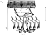
- Fig. 2 shows a top view of the above-described soil tillage implement 1 in the right-handed working position.
- the cross frames 11 and 12 are now rotated by 180° around their turning axis running parallel to the working direction A, which results in the right-handed working position of the Plough body is used to work the soil.
- the packer roller is set with the setting mechanism 40 by a right angle of attack ⁇ 2 relative to the working direction A. Although this has the same value as the angle of attack ⁇ 1, the deflection direction now points to the right.
- the axis of rotation R is therefore rotated clockwise by the angle ⁇ 2 relative to a perpendicular to the working direction A.
- the packer roller is offset to the right side of the soil cultivation unit 10, i.e. the full-turn parallel plough. This ensures that the packer roller, when the full-turn parallel plough is in the right-hand working position, also drives over a right side area C to the right of the plough body and reworks it, e.g. reconsolidates it, into which a plough body arranged furthest to the right deposits the soil bar it has worked and turned to the right.
- the packer roller exerts a lateral pulling force on the soil tillage unit 10 during operation, as illustrated below using the example of the left-turning working position. A similar consideration applies to the right-turning working position.
- the left-turning working position means that the tillage tools 13 of the tillage unit 10 turn the soil to the left, which leads to a lateral pull of the tillage unit 10 to the right.
- the soil preparation unit 20, in this case the packer roller is set at an angle of attack ⁇ 1 to the left relative to the working direction A, which, due to its interaction with the soil, results in a lateral pulling force directed to the left.
- the full-turn parallel plough pulls the soil preparation implement 1 to the right, while the packer roller pulls the soil preparation implement 1 to the left.
- the magnitude of the lateral pulling force of the soil preparation unit 20 can be can be adjusted within certain limits via the size of the angle of attack ⁇ 1 and via the force with which the soil post-processing unit 20 interacts with the soil. With a suitable selection of the angle of attack, a straight-line running of the soil cultivation device 1 can be ensured by means of the packer roller.
- the steering rods 41 and 42 are on the soil tillage implement 1, which is Fig. 1 and Fig. 2 shown, arranged so that they diverge in the working direction A. This means that a distance between both handlebars 41 and 42 increases towards the front. In other words, as in Fig. 2 As shown, a first attachment distance W1 between the soil cultivation unit attachments 31 and 32, which corresponds to the distance between the front ends of the steering rods 41 and 42, is greater than a second attachment distance W2 between the soil post-processing unit attachments 21 and 22, which corresponds to the distance between the rear ends of the steering rods 41 and 42.
- the lengths of the steering rods 41 and 42 are equal in this embodiment, so that the first and second soil cultivation unit attachments 31, 32 and the first and second soil post-processing unit attachments 21 and 22 span a steering trapezoid, in particular in a neutral position of the packer roller in which the rotation axis R is perpendicular to the working direction A.
- This design of the steering rods 41 and 42 ensures that the adjustment mechanism 40 simultaneously moves the packer roller to one side of the soil tillage implement 1 and adjusts it at an angle of attack in the same direction.
- the adjustment mechanism 40 has a hydraulic cylinder 43. This is connected at a first end via a joint to the second steering rod 42 and at a second, other end via a another joint connected to one or both of the crossbeams 33, 34.
- the hydraulic cylinder 43 In the left-turning working position of the soil tillage implement 1 shown, the hydraulic cylinder 43 is in a first, extended position, which results in the packer roller being displaced and adjusted to the left. This first position corresponds to a first end stop with an angle of attack ⁇ 1. The lateral pulling force exerted by the packer roller is transmitted to the hitch 30 by the adjustment mechanism 40.
- the hydraulic cylinder 43 In the working position of the soil tillage implement 1 shown, the hydraulic cylinder 43 is in a second, retracted position, which results in the packer roller being displaced and adjusted to the right. This second position corresponds to a second end stop with an angle of attack ⁇ 2. The lateral pulling force exerted by the packer roller is also transmitted to the hitch 30 by the adjustment mechanism 40 in the second position.
- first and second end stops do not necessarily have to correspond to the extended or retracted position of the hydraulic cylinder 43; intermediate positions can also be defined as the working position if necessary.
- the angles of attack ⁇ 1, ⁇ 2 can be adjusted by adjusting the first and second end stops.
- the angle of attack can also be adjusted by changing the geometry of the steering trapezoid spanned by the first and second soil tillage unit attachments 31 and 32 and by the first and second soil post-treatment unit attachments 21 and 22, for example by changing the lengths of the first and second steering rods 41, 42.
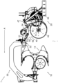
- Fig. 3 shows the above-described soil tillage implement 1 in a further right-turning working position.
- the second mounting distance W2 between the first soil preparation unit mounting 21 and the second soil preparation unit mounting 22 is larger and thus closer to the first mounting distance W1.
- the steering trapezoid formed by the first and second soil preparation unit mountings 31 and 32 and the first and second soil preparation unit mountings 21 and 22 approaches Fig. 2 a parallelogram.
- the changed geometry of the steering trapezoid results in the angle of attack ⁇ 2 being smaller than in the Fig. 2 shown setting, although the packer roller is offset laterally by a greater distance.
- Fig. 4 shows the tillage implement 1 from Fig. 1 in a side view.
- the bridge-shaped hitch 30, to which the packer roller is attached behind the plough bodies, is clearly visible.
- the full-turn parallel plough is in the right-hand working position, ie the right-hand tillage tools 13 are arranged for tilling the soil.
- the packer roller is in Fig. 4 shifted in the direction of view and positioned opposite to it, ie the rotation axis R of the packer roller is not exactly perpendicular to the drawing plane.
- the packer roller is attached to the hitch 30 of the soil tillage implement 1 by means of the adjustment mechanism 40.
- the left steering rod 42 which is pivotally attached to the soil tillage unit attachment 32, can be seen in the illustration as part of the adjustment mechanism 40.
- the steering rod 42 is constructed in several parts and comprises an upper steering rod leg 51, a lower steering rod leg 52, a front steering rod leg 53, and a rear steering rod leg 54.
- the front steering rod leg 53 and the rear steering rod leg 54 are each rotatably connected at one of their two ends to the upper steering rod leg 51 and the lower steering rod leg 52, respectively.
- the steering rod legs 51, 52, 53, 54 thus form the legs of a parallelogram height guide 50.
- the parallelogram height guide 50 By means of the parallelogram height guide 50, it is possible to adjust the height of the packer roller relative to the height of the plough bodies.
- the packer roller applies part of the weight of the soil tillage implement 1 to the soil.
- the distribution of this weight between the soil preparation unit 20, the soil tillage tools 13, and a tractor (not shown) connected to the soil tillage implement 1 can be influenced and adjusted using this parallelogram height guide 50.
- rotating disc coulters 45 are attached to the packer roller to enhance the interaction of the soil preparation unit 20 with the soil, in particular the lateral traction that can be applied.
- the disc coulters 45 rotate about their own rotation axes S, which are arranged parallel to the rotation axis R of the packer roller. If necessary, the Rotation axes S can also be further adjusted relative to the rotation axis R.
- a packer roller attachment 46 that glides through the soil during cultivation.
- the attachment 46 is set at the same angle to working direction A as the packer roller, thereby increasing the lateral traction exerted by the packer roller on the soil cultivation implement 1.
- the attachment 46 is connected to the packer roller via a folding joint 47 such that the attachment 46 can be lifted out of the soil if necessary.
- the folding attachment 46 can be used to selectively increase interaction with the soil, e.g., lateral traction, if necessary.
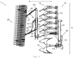
- Fig. 5 shows a further embodiment of a soil tillage implement 1 in a transport position. Identical and corresponding elements of the soil tillage implement 1 from Fig. 5 and that of one of the other figures are designated by the same reference numerals where appropriate.
- the soil tillage unit 10 also in this embodiment a full-turn parallel plough, has a first transverse frame 111, which is carried by a first boom 61. Plough bodies as soil tillage tools 13 are mounted in a row on the first transverse frame 111.
- the first boom 61 is hingedly connected to a soil tillage implement frame 60 via a first lifting axle U1. The first boom 61 can thus be lowered downwards and raised upwards.
- the soil tillage unit 10 of Fig. 5 also has a second transverse frame 112, which is perpendicular to the plane of the drawing of Fig. 5 and also carries the plough body.
- This second cross frame 112 is shown in Fig. 5 shown embodiment in contrast to the first cross frame 111 cannot be lifted upwards into a separate transport position.
- the first transverse frame 111 is arranged on the right side of the soil tillage implement 1, as seen in the working direction A. It is preferred that a corresponding first transverse frame (not shown) is also arranged on the left side of the soil tillage implement 1.
- a soil preparation unit 20, also a packer roller in this embodiment, is attached to a towing device 30 with a second boom 62.
- the second boom 62 is attached to the towing device 30 at one end so as to be rotatable about a second lifting axis U2 and carries a crossbeam 133 rotatably mounted at its other end.
- the packer roller is attached to the crossbeam 133 in the manner described in more detail below.
- the crossbeam 133 can be moved from a working position of the soil cultivation device 1 (not shown here), in which it is essentially parallel to the ground, ie in Fig. 5 perpendicular to the plane of the drawing, into which Fig. 5 shown transport position, in which it extends substantially perpendicular to the ground.
- Another foldable second boom (not shown), mounted on the left side of the hitch 30, carries another packer roller (not shown) in a similar manner.
- the crossbeam 133 has a first tillage unit attachment 131 at one free end and a second tillage unit attachment 132 at its other free end.
- One end of a first steering rod 41 is pivotally attached to the tillage unit attachment 131, and one end of a second steering rod 42 is pivotally attached to the tillage unit attachment 132.
- the other Ends of these steering rods 41 and 42 are pivotally attached to the soil preparation unit attachments 21 and 22, respectively, so that the packer roller is supported by the steering rods 41, 42.
- the alignment of the first and second steering rods 41, 42 determines in the Fig. 5 shown transport position, a transport height H of the soil preparation unit 20 and thus also, to a large extent, of the soil cultivation device 1, which can be set by the adjustment mechanism 40 to be lower than a permissible road transport height, as far as this is possible due to the dimensions of the soil cultivation unit 10.
- the soil preparation unit 20 is lowered as far as possible in the transport position.
- the hydraulic cylinder 43 of the adjustment mechanism 40 is brought into a fully extended position for the packer roller shown.
- a deviation of the trapezoidal shape from a parallelogram results in an inclination angle of the packer roller relative to the vertical.
- this inclination angle can be set to zero by adjusting the distance between the tillage unit attachments 21, 22.
- the tillage unit attachments 131, 132 and the post-cultivation unit attachments 21, 22 then form a parallelogram, which in Fig. 5 but is not shown.
Landscapes
- Life Sciences & Earth Sciences (AREA)
- Engineering & Computer Science (AREA)
- Mechanical Engineering (AREA)
- Soil Sciences (AREA)
- Environmental Sciences (AREA)
- Soil Working Implements (AREA)
Claims (14)
- Appareil de travail du sol (1), pourvu d'une unité de travail du sol (10) destinée à travailler le sol avec des outils de de travail du sol (13) le long d'une direction de travail (A), qui est conçue pour, dans une première position de travail, procéder à un travail du sol tourné vers la gauche et dans une deuxième position de travail, procéder à un travail du sol tourné vers la droite,sur l'unité de travail du sol, une unité de post-travail du sol (20) étant montée de telle sorte que l'unité de post-travail du sol soit placée derrière l'unité de travail du sol dans la direction de travail,caractérisé en ce que l'unité de post-travail du sol est montée au moyen d'un mécanisme de mise en prise (40) pivotant,par le mécanisme de mise en prise, l'unité de post-travail du sol étant déplaçable latéralement en rapport à la direction de travail et étant susceptible d'être mise en prise vers les deux côtés sous un angle d'attaque (α1, α2) à l'égard de la direction de travail, pour exercer une force de traction latérale réglable par une interaction avec le sol sur l'appareil de travail du sol.
- Appareil de travail du sol (1) selon la revendication 1 le mécanisme de mise en prise (40) comportant une première bielle de direction (41) d'une première longueur de bielle de direction et une deuxième bielle de direction (42) d'une deuxième longueur de bielle de direction, lesquelles relient ensemble l'unité de post-travail du sol (20) et l'appareil de travail du sol,
la première bielle de direction s'étendant entre un premier montage (31, 131) de l'unité de travail du sol sur l'unité de travail du sol (10) et un premier montage (21) de l'unité de post-travail du sol sur l'unité de post-travail du sol (20) et la deuxième bielle de direction s'étendant en un deuxième montage (32, 132) de l'unité de travail du sol sur l'unité de travail du sol et un deuxième montage (22) de l'unité de post-travail du sol (22) sur l'unité de post-travail du sol,a) la première bielle de direction et la deuxième bielle de direction divergeant dans la direction de travail (A) oub) la première bielle de direction et la deuxième bielle de direction s'écoulant à la parallèle l'une de l'autre et la première longueur de bielle de direction et / ou la deuxième longueur de bielle de direction étant réglable. - Appareil de travail du sol (1) selon la revendication 2, le premier montage (21) d'unité de post-travail du sol (21) et le deuxième montage (22) d'unité de post-travail du étant placé sur l'unité de post-travail du sol dans la direction de travail (A), de telle sorte que l'unité de post-travail du sol (20) se trouve en majeure partie à l'avant ou à l'arrière du premier montage de l'unité de post-travail du sol et du deuxième montage de l'unité de post-travail du sol, dans la direction de travail.
- Appareil de travail du sol (1) selon l'une quelconque des revendications 1 à 3, l'unité de travail du sol (10) étant une charrue, de préférence une charrue réversible, de manière particulièrement préférentielle, une charrue totalement réversible, de manière tout particulièrement préférentielle, une charrue parallèle totalement réversible, les outils de travail du sol (13) étant des corps de charrue.
- Appareil de travail du sol (1) selon l'une quelconque des revendications 1 à 4, l'unité de post-travail du sol (20) étant conçue pour provoquer une reconsolidation, un aplanissement ou un ensemencement et étant notamment un rouleau Packer, un rouleau cage, un rouleau porte-lame, un rouleau de guidage en profondeur, une herse rotative, une barre de coupe, une barre à dents, une barre niveleuse ou une barre de semis.
- Appareil de travail du sol (1) selon l'une quelconque des revendications 1 à 5, une profondeur de travail des outils de travail du sol (10) étant réglable de préférence à l'égard de l'unité de post-travail du sol (20), de préférence le mécanisme de mise en prise (40) comportant un guidage en hauteur, notamment un parallélogramme de guidage en hauteur (50) pour provoquer un réglage et / ou une modification de la profondeur de travail des outils de travail du sol à l'encontre de l'unité de post-travail du sol (20), indépendamment de l'angle d'attaque (α1, α2) réglé.
- Appareil de travail du sol (1) selon l'une quelconque des revendications 1 à 6, l'appareil de travail du sol comportant une première butée de fin de course et une deuxième butée de fin de course pour le mécanisme de mise en prise (40) par laquelle l'angle d'attaque (α1, α2) est pré-réglable vers la gauche et vers la droite, en rapport à la direction de travail (A),
l'angle d'attaque étant susceptible d'être changé entre la droite et la gauche, notamment par changement du mécanisme de mise en prise entre la première butée de fin de course et la deuxième butée de fin de course. - Appareil de travail du sol (1) selon la revendication 1 ou la revendication 2 et l'une quelconque des revendications 3 à 7, l'angle d'attaque (α1, α2) étant réglable de manière variable,notamment en ce qu'un premier écart de montage (W1) entre le premier montage (31, 131) de l'unité de travail du sol et le deuxième montage (32, 132) de l'unité de travail du sol est réglable de manière variable,notamment en ce qu'un deuxième écart de montage (W2) entre le premier montage de l'unité de post-travail du solet le deuxième montage de l'unité de post-travail du sol est réglable de manière variable et / ounotamment en ce que la première longueur de bielle de direction et / ou la deuxième longueur de bielle de direction est réglable de manière variable.
- Appareil de travail du sol (1) selon la revendication 8, l'angle d'attaque (α1, α2) étant réglable de manière variable, mécaniquement par des positions d'enclenchement déterminées, mécaniquement par une précontrainte par ressort, par un servomoteur par commande par un utilisateur et / ou hydrauliquement par une commande automatique.
- Appareil de travail du sol (1) selon l'une quelconque des revendications 1 à 9, le mécanisme de mise en prise (40) étant conçu pour provoquer par l'intermédiaire d'un entraînement forcé ou une commande séquentielle une mise en prise de l'unité de post-travail du sol (20) par suite d'un changement de l'unité de travail du sol (10) entre la première position de travail et la deuxième position de travail.
- Appareil de travail du sol (1) selon l'une quelconque des revendications 1 à 10, qui peut se basculer à partir d'au moins l'une des positions de travail dans une position de transport, dans laquelle l'unité de post-travail du sol (20) s'étend principalement à la verticale et dans laquelle il présente une hauteur de travail (H),le mécanisme de mise en prise (40) étant conçu de préférence pour régler une position verticale de l'unité de post-travail du sol en rapport à un cadre (60) de l'appareil de travail, en option au moyen d'un mécanisme à ressort,de telle sorte que la hauteur de transport (H) n'excède pas une hauteur autorisée de transport sur route.
- Appareil de travail du sol (1) selon la revendication 1 ou la revendication 2 et l'une quelconque des revendications 3 à 11, l'unité de travail du sol (10) portant les outils de travail du sol sur au moins trois cadres transversaux, qui s'étendent ensemble en une largeur de travail, au moins pour le cadre extrême à droite et le cadre extrême à gauche étant prévu un mécanisme de mise en prise (40), au moyen duquel chaque fois une unité de post-travail du sol (20) est montée sur le cadre transversal respectif et qui comporte respectivement la première bielle de direction (41) et la deuxième bielle de direction (42).
- Appareil de travail du sol (1) selon l'une quelconque des revendications 1 à 12, l'unité de post-travail du sol (20) comprenant par ailleurs un outil de guidage, notamment un coutre circulaire (45) et / ou un appui (46), qui est de préférence susceptible d'être amené en interaction avec le sol, pour influencer la force de traction latérale.
- Appareil de travail du sol (1) selon l'une quelconque des revendications 1 à 13, à l'avant et / ou à l'arrière de l'unité de post-travail du sol (20) étant placé un système distributeur, destiné à épandre des matières solides et / ou liquides, notamment des agents fertilisants et / ou des semences.
Applications Claiming Priority (1)
| Application Number | Priority Date | Filing Date | Title |
|---|---|---|---|
| DE102021214803.4A DE102021214803A1 (de) | 2021-12-21 | 2021-12-21 | Bodenbearbeitungsgerät |
Publications (3)
| Publication Number | Publication Date |
|---|---|
| EP4201166A1 EP4201166A1 (fr) | 2023-06-28 |
| EP4201166C0 EP4201166C0 (fr) | 2025-05-07 |
| EP4201166B1 true EP4201166B1 (fr) | 2025-05-07 |
Family
ID=84541505
Family Applications (1)
| Application Number | Title | Priority Date | Filing Date |
|---|---|---|---|
| EP22214628.4A Active EP4201166B1 (fr) | 2021-12-21 | 2022-12-19 | Outil de travail du sol |
Country Status (2)
| Country | Link |
|---|---|
| EP (1) | EP4201166B1 (fr) |
| DE (1) | DE102021214803A1 (fr) |
Family Cites Families (6)
| Publication number | Priority date | Publication date | Assignee | Title |
|---|---|---|---|---|
| AT353042B (de) * | 1977-09-12 | 1979-10-25 | Ferd Heger & Sohn Landw Maschi | Nivellier- und kruemlerwalzenanordnung |
| DE2752764A1 (de) * | 1977-11-25 | 1979-05-31 | Bayerische Pflugfabrik Gmbh | Geraetekombination zur bodenbearbeitung |
| DE7804395U1 (de) | 1978-02-15 | 1981-02-19 | Rabewerk Heinrich Clausing, 4515 Bad Essen | Bodenbearbeitungsgeraet |
| DE3412512A1 (de) * | 1983-04-06 | 1984-10-11 | National Research Development Corp., London | Bodenbearbeitungsvorrichtung |
| DE19832620A1 (de) | 1998-07-21 | 2000-01-27 | Dietmar Groh | Vorrichtung zur mehrschichtigen Bodenbearbeitung |
| DE10147595B4 (de) | 2001-09-26 | 2018-05-09 | Amazonen-Werke H. Dreyer Gmbh & Co. Kg | Bodenbearbeitungskombination |
-
2021
- 2021-12-21 DE DE102021214803.4A patent/DE102021214803A1/de active Pending
-
2022
- 2022-12-19 EP EP22214628.4A patent/EP4201166B1/fr active Active
Also Published As
| Publication number | Publication date |
|---|---|
| EP4201166C0 (fr) | 2025-05-07 |
| DE102021214803A1 (de) | 2023-06-22 |
| EP4201166A1 (fr) | 2023-06-28 |
Similar Documents
| Publication | Publication Date | Title |
|---|---|---|
| DE2838829C2 (de) | Mehrschariger Aufsattelpflug | |
| DE102014109605B4 (de) | Schwenkstützrad zum Anbau an einen Pflugrahmen | |
| DE69012588T2 (de) | Maschine zum Zetten, Wenden und Sammeln von Heu, Stroh und ähnlichem Erntegut. | |
| EP0062734A1 (fr) | Charrue avec ligne de force de la coupe et point d'attache de traction réglable | |
| DE3004576A1 (de) | Kombinatsgeraet zur bodenbearbeitung | |
| DE2641956A1 (de) | Vorrichtung zum pfluegen | |
| EP3800976B1 (fr) | Appareil agricole de travail du sol et procédé permettant de faire fonctionner ledit appareil | |
| DE3529517C2 (de) | Pflug | |
| EP3434089B1 (fr) | Machine agricole de traitement du sol | |
| DE3530107C2 (de) | Pflug | |
| EP4201166B1 (fr) | Outil de travail du sol | |
| EP3381253A1 (fr) | Engin agricole doté d'éléments de guidage en profondeur | |
| DE4306145A1 (de) | Gerätekombination zum Pflügen landwirtschaftlicher Nutzflächen und zur Bodennachbearbeitung und/oder Bodenbestellung | |
| DE4031504C2 (de) | Aufsatteldrehpflug mit variabler Arbeitsbreiteneinstellung | |
| DE2639608C2 (fr) | ||
| DE4017379C1 (en) | Cable plough towable for cable laying - allows distance between front wheels and share to be varied and fixed in selected position | |
| EP1625781B1 (fr) | Charrue portée réversible | |
| EP2371194B1 (fr) | Dispositif de répartition de semences et/ou d'engrais | |
| DE69910904T2 (de) | Sähmaschine | |
| DE69910683T2 (de) | Sähmaschine | |
| DE2450386A1 (de) | Pflugsystem mit mehreren einzelpfluegen kontinuierlich einstellbarem abstand | |
| DE4031503C2 (de) | Aufsatteldrehpflug | |
| DE69601504T2 (de) | Mehrschariger anhängedrehpflug | |
| DE3306650C2 (fr) | ||
| DE19637536C2 (de) | Integrierte Kombination aus einem Pflug und einer Bodenaufbereitungsvorrichtung |
Legal Events
| Date | Code | Title | Description |
|---|---|---|---|
| PUAI | Public reference made under article 153(3) epc to a published international application that has entered the european phase |
Free format text: ORIGINAL CODE: 0009012 |
|
| STAA | Information on the status of an ep patent application or granted ep patent |
Free format text: STATUS: THE APPLICATION HAS BEEN PUBLISHED |
|
| AK | Designated contracting states |
Kind code of ref document: A1 Designated state(s): AL AT BE BG CH CY CZ DE DK EE ES FI FR GB GR HR HU IE IS IT LI LT LU LV MC ME MK MT NL NO PL PT RO RS SE SI SK SM TR |
|
| STAA | Information on the status of an ep patent application or granted ep patent |
Free format text: STATUS: REQUEST FOR EXAMINATION WAS MADE |
|
| 17P | Request for examination filed |
Effective date: 20240102 |
|
| RBV | Designated contracting states (corrected) |
Designated state(s): AL AT BE BG CH CY CZ DE DK EE ES FI FR GB GR HR HU IE IS IT LI LT LU LV MC ME MK MT NL NO PL PT RO RS SE SI SK SM TR |
|
| GRAP | Despatch of communication of intention to grant a patent |
Free format text: ORIGINAL CODE: EPIDOSNIGR1 |
|
| STAA | Information on the status of an ep patent application or granted ep patent |
Free format text: STATUS: GRANT OF PATENT IS INTENDED |
|
| RIC1 | Information provided on ipc code assigned before grant |
Ipc: A01B 49/02 20060101ALI20240510BHEP Ipc: A01B 17/00 20060101AFI20240510BHEP |
|
| INTG | Intention to grant announced |
Effective date: 20240610 |
|
| RAP3 | Party data changed (applicant data changed or rights of an application transferred) |
Owner name: LEMKEN GMBH & CO. KG |
|
| GRAJ | Information related to disapproval of communication of intention to grant by the applicant or resumption of examination proceedings by the epo deleted |
Free format text: ORIGINAL CODE: EPIDOSDIGR1 |
|
| STAA | Information on the status of an ep patent application or granted ep patent |
Free format text: STATUS: REQUEST FOR EXAMINATION WAS MADE |
|
| INTC | Intention to grant announced (deleted) | ||
| GRAP | Despatch of communication of intention to grant a patent |
Free format text: ORIGINAL CODE: EPIDOSNIGR1 |
|
| STAA | Information on the status of an ep patent application or granted ep patent |
Free format text: STATUS: GRANT OF PATENT IS INTENDED |
|
| INTG | Intention to grant announced |
Effective date: 20241203 |
|
| GRAS | Grant fee paid |
Free format text: ORIGINAL CODE: EPIDOSNIGR3 |
|
| GRAA | (expected) grant |
Free format text: ORIGINAL CODE: 0009210 |
|
| STAA | Information on the status of an ep patent application or granted ep patent |
Free format text: STATUS: THE PATENT HAS BEEN GRANTED |
|
| AK | Designated contracting states |
Kind code of ref document: B1 Designated state(s): AL AT BE BG CH CY CZ DE DK EE ES FI FR GB GR HR HU IE IS IT LI LT LU LV MC ME MK MT NL NO PL PT RO RS SE SI SK SM TR |
|
| REG | Reference to a national code |
Ref country code: GB Ref legal event code: FG4D Free format text: NOT ENGLISH |
|
| REG | Reference to a national code |
Ref country code: CH Ref legal event code: EP |
|
| REG | Reference to a national code |
Ref country code: DE Ref legal event code: R096 Ref document number: 502022003857 Country of ref document: DE |
|
| REG | Reference to a national code |
Ref country code: IE Ref legal event code: FG4D Free format text: LANGUAGE OF EP DOCUMENT: GERMAN |
|
| U01 | Request for unitary effect filed |
Effective date: 20250516 |
|
| U07 | Unitary effect registered |
Designated state(s): AT BE BG DE DK EE FI FR IT LT LU LV MT NL PT RO SE SI Effective date: 20250522 |
|
| PG25 | Lapsed in a contracting state [announced via postgrant information from national office to epo] |
Ref country code: ES Free format text: LAPSE BECAUSE OF FAILURE TO SUBMIT A TRANSLATION OF THE DESCRIPTION OR TO PAY THE FEE WITHIN THE PRESCRIBED TIME-LIMIT Effective date: 20250507 |
|
| PG25 | Lapsed in a contracting state [announced via postgrant information from national office to epo] |
Ref country code: GR Free format text: LAPSE BECAUSE OF FAILURE TO SUBMIT A TRANSLATION OF THE DESCRIPTION OR TO PAY THE FEE WITHIN THE PRESCRIBED TIME-LIMIT Effective date: 20250808 Ref country code: NO Free format text: LAPSE BECAUSE OF FAILURE TO SUBMIT A TRANSLATION OF THE DESCRIPTION OR TO PAY THE FEE WITHIN THE PRESCRIBED TIME-LIMIT Effective date: 20250807 |
|
| PG25 | Lapsed in a contracting state [announced via postgrant information from national office to epo] |
Ref country code: PL Free format text: LAPSE BECAUSE OF FAILURE TO SUBMIT A TRANSLATION OF THE DESCRIPTION OR TO PAY THE FEE WITHIN THE PRESCRIBED TIME-LIMIT Effective date: 20250507 |
|
| PG25 | Lapsed in a contracting state [announced via postgrant information from national office to epo] |
Ref country code: HR Free format text: LAPSE BECAUSE OF FAILURE TO SUBMIT A TRANSLATION OF THE DESCRIPTION OR TO PAY THE FEE WITHIN THE PRESCRIBED TIME-LIMIT Effective date: 20250507 |
|
| PG25 | Lapsed in a contracting state [announced via postgrant information from national office to epo] |
Ref country code: RS Free format text: LAPSE BECAUSE OF FAILURE TO SUBMIT A TRANSLATION OF THE DESCRIPTION OR TO PAY THE FEE WITHIN THE PRESCRIBED TIME-LIMIT Effective date: 20250807 |
|
| PG25 | Lapsed in a contracting state [announced via postgrant information from national office to epo] |
Ref country code: IS Free format text: LAPSE BECAUSE OF FAILURE TO SUBMIT A TRANSLATION OF THE DESCRIPTION OR TO PAY THE FEE WITHIN THE PRESCRIBED TIME-LIMIT Effective date: 20250907 |
|
| PG25 | Lapsed in a contracting state [announced via postgrant information from national office to epo] |
Ref country code: SM Free format text: LAPSE BECAUSE OF FAILURE TO SUBMIT A TRANSLATION OF THE DESCRIPTION OR TO PAY THE FEE WITHIN THE PRESCRIBED TIME-LIMIT Effective date: 20250507 |
|
| PG25 | Lapsed in a contracting state [announced via postgrant information from national office to epo] |
Ref country code: CZ Free format text: LAPSE BECAUSE OF FAILURE TO SUBMIT A TRANSLATION OF THE DESCRIPTION OR TO PAY THE FEE WITHIN THE PRESCRIBED TIME-LIMIT Effective date: 20250507 |
|
| PG25 | Lapsed in a contracting state [announced via postgrant information from national office to epo] |
Ref country code: SK Free format text: LAPSE BECAUSE OF FAILURE TO SUBMIT A TRANSLATION OF THE DESCRIPTION OR TO PAY THE FEE WITHIN THE PRESCRIBED TIME-LIMIT Effective date: 20250507 |
|
| U20 | Renewal fee for the european patent with unitary effect paid |
Year of fee payment: 4 Effective date: 20260102 |
|
| PLBE | No opposition filed within time limit |
Free format text: ORIGINAL CODE: 0009261 |
|
| STAA | Information on the status of an ep patent application or granted ep patent |
Free format text: STATUS: NO OPPOSITION FILED WITHIN TIME LIMIT |
|
| REG | Reference to a national code |
Ref country code: CH Ref legal event code: L10 Free format text: ST27 STATUS EVENT CODE: U-0-0-L10-L00 (AS PROVIDED BY THE NATIONAL OFFICE) Effective date: 20260318 |
|
| 26N | No opposition filed |
Effective date: 20260210 |