EP4200971B1 - Verfahren zur bestimmung einer synchrondrehzahl - Google Patents
Verfahren zur bestimmung einer synchrondrehzahl Download PDFInfo
- Publication number
- EP4200971B1 EP4200971B1 EP21762434.5A EP21762434A EP4200971B1 EP 4200971 B1 EP4200971 B1 EP 4200971B1 EP 21762434 A EP21762434 A EP 21762434A EP 4200971 B1 EP4200971 B1 EP 4200971B1
- Authority
- EP
- European Patent Office
- Prior art keywords
- frequency
- speed
- synchronous speed
- clock frequency
- machine
- Prior art date
- Legal status (The legal status is an assumption and is not a legal conclusion. Google has not performed a legal analysis and makes no representation as to the accuracy of the status listed.)
- Active
Links
Images


Classifications
-
- H—ELECTRICITY
- H02—GENERATION; CONVERSION OR DISTRIBUTION OF ELECTRIC POWER
- H02P—CONTROL OR REGULATION OF ELECTRIC MOTORS, ELECTRIC GENERATORS OR DYNAMO-ELECTRIC CONVERTERS; CONTROLLING TRANSFORMERS, REACTORS OR CHOKE COILS
- H02P23/00—Arrangements or methods for the control of AC motors characterised by a control method other than vector control
- H02P23/14—Estimation or adaptation of motor parameters, e.g. rotor time constant, flux, speed, current or voltage
-
- F—MECHANICAL ENGINEERING; LIGHTING; HEATING; WEAPONS; BLASTING
- F04—POSITIVE - DISPLACEMENT MACHINES FOR LIQUIDS; PUMPS FOR LIQUIDS OR ELASTIC FLUIDS
- F04D—NON-POSITIVE-DISPLACEMENT PUMPS
- F04D1/00—Radial-flow pumps, e.g. centrifugal pumps; Helico-centrifugal pumps
-
- F—MECHANICAL ENGINEERING; LIGHTING; HEATING; WEAPONS; BLASTING
- F04—POSITIVE - DISPLACEMENT MACHINES FOR LIQUIDS; PUMPS FOR LIQUIDS OR ELASTIC FLUIDS
- F04D—NON-POSITIVE-DISPLACEMENT PUMPS
- F04D13/00—Pumping installations or systems
- F04D13/02—Units comprising pumps and their driving means
- F04D13/06—Units comprising pumps and their driving means the pump being electrically driven
-
- F—MECHANICAL ENGINEERING; LIGHTING; HEATING; WEAPONS; BLASTING
- F04—POSITIVE - DISPLACEMENT MACHINES FOR LIQUIDS; PUMPS FOR LIQUIDS OR ELASTIC FLUIDS
- F04D—NON-POSITIVE-DISPLACEMENT PUMPS
- F04D15/00—Control, e.g. regulation, of pumps, pumping installations or systems
- F04D15/0066—Control, e.g. regulation, of pumps, pumping installations or systems by changing the speed, e.g. of the driving engine
-
- F—MECHANICAL ENGINEERING; LIGHTING; HEATING; WEAPONS; BLASTING
- F04—POSITIVE - DISPLACEMENT MACHINES FOR LIQUIDS; PUMPS FOR LIQUIDS OR ELASTIC FLUIDS
- F04D—NON-POSITIVE-DISPLACEMENT PUMPS
- F04D15/00—Control, e.g. regulation, of pumps, pumping installations or systems
- F04D15/0088—Testing machines
-
- G—PHYSICS
- G01—MEASURING; TESTING
- G01H—MEASUREMENT OF MECHANICAL VIBRATIONS OR ULTRASONIC, SONIC OR INFRASONIC WAVES
- G01H1/00—Measuring characteristics of vibrations in solids by using direct conduction to the detector
- G01H1/003—Measuring characteristics of vibrations in solids by using direct conduction to the detector of rotating machines
-
- G—PHYSICS
- G01—MEASURING; TESTING
- G01H—MEASUREMENT OF MECHANICAL VIBRATIONS OR ULTRASONIC, SONIC OR INFRASONIC WAVES
- G01H3/00—Measuring characteristics of vibrations by using a detector in a fluid
- G01H3/04—Frequency
- G01H3/08—Analysing frequencies present in complex vibrations, e.g. comparing harmonics present
-
- G—PHYSICS
- G01—MEASURING; TESTING
- G01P—MEASURING LINEAR OR ANGULAR SPEED, ACCELERATION, DECELERATION, OR SHOCK; INDICATING PRESENCE, ABSENCE, OR DIRECTION, OF MOVEMENT
- G01P3/00—Measuring linear or angular speed; Measuring differences of linear or angular speeds
- G01P3/02—Devices characterised by the use of mechanical means
-
- G—PHYSICS
- G10—MUSICAL INSTRUMENTS; ACOUSTICS
- G10K—SOUND-PRODUCING DEVICES; METHODS OR DEVICES FOR PROTECTING AGAINST, OR FOR DAMPING, NOISE OR OTHER ACOUSTIC WAVES IN GENERAL; ACOUSTICS NOT OTHERWISE PROVIDED FOR
- G10K11/00—Methods or devices for transmitting, conducting or directing sound in general; Methods or devices for protecting against, or for damping, noise or other acoustic waves in general
- G10K11/16—Methods or devices for protecting against, or for damping, noise or other acoustic waves in general
-
- F—MECHANICAL ENGINEERING; LIGHTING; HEATING; WEAPONS; BLASTING
- F05—INDEXING SCHEMES RELATING TO ENGINES OR PUMPS IN VARIOUS SUBCLASSES OF CLASSES F01-F04
- F05D—INDEXING SCHEME FOR ASPECTS RELATING TO NON-POSITIVE-DISPLACEMENT MACHINES OR ENGINES, GAS-TURBINES OR JET-PROPULSION PLANTS
- F05D2270/00—Control
- F05D2270/30—Control parameters, e.g. input parameters
- F05D2270/301—Pressure
- F05D2270/3015—Pressure differential pressure
-
- F—MECHANICAL ENGINEERING; LIGHTING; HEATING; WEAPONS; BLASTING
- F05—INDEXING SCHEMES RELATING TO ENGINES OR PUMPS IN VARIOUS SUBCLASSES OF CLASSES F01-F04
- F05D—INDEXING SCHEME FOR ASPECTS RELATING TO NON-POSITIVE-DISPLACEMENT MACHINES OR ENGINES, GAS-TURBINES OR JET-PROPULSION PLANTS
- F05D2270/00—Control
- F05D2270/30—Control parameters, e.g. input parameters
- F05D2270/334—Vibration measurements
-
- H—ELECTRICITY
- H02—GENERATION; CONVERSION OR DISTRIBUTION OF ELECTRIC POWER
- H02P—CONTROL OR REGULATION OF ELECTRIC MOTORS, ELECTRIC GENERATORS OR DYNAMO-ELECTRIC CONVERTERS; CONTROLLING TRANSFORMERS, REACTORS OR CHOKE COILS
- H02P2207/00—Indexing scheme relating to controlling arrangements characterised by the type of motor
- H02P2207/01—Asynchronous machines
Definitions
- the present invention relates to a method for determining a synchronous speed of an electric machine in a work machine driven by the electric machine.
- the invention also relates to a processing device, a system and a computer program.
- the operating point of a fluid flow machine in particular a centrifugal pump arrangement, consisting of a pump and the electrical machine driving it, in particular an asynchronous machine, a statement about its operating point is often required.
- the operating point of a fluid flow machine, in particular a centrifugal pump, on its flow rate-head characteristic curve or QH characteristic curve, is characterized in particular by its flow rate, also referred to below as the flow rate.
- the flow rate also referred to below as the flow rate.
- the head is estimated as the quotient of the pressure difference, density and acceleration due to gravity.
- a pressure difference of 1 bar corresponds to a head of approx. 10 meters. Furthermore, an operating point of a centrifugal pump is determined by an electrical measurement, The output motor power is calculated from a current and voltage measurement, taking into account the efficiency of the motor.
- a device and a method are known for determining the operating point of a working machine and/or an asynchronous motor driving it.
- the method and the device disclosed therein can be used for uncontrolled asynchronous machines or machines running on the mains, since in these cases the synchronous speed of the electrical machine is known.
- the synchronous speed is calculated, for example, from the mains frequency multiplied by the number of pole pairs.
- determining the operating point of the working machine is problematic if it is driven by a speed-controlled asynchronous machine and the synchronous speed is therefore not known.
- the DE 10 2017 213 131 A1 discloses controlling an actuator by determining a noise emission and/or vibration emission by means of at least one acoustic sensor while the actuator is operated at a predefined operating point, and changing the operating point of the actuator when the noise emission and/or vibration is in a predefined undesirable range.
- the DE 10 2006 008 048 A1 discloses a motor speed detecting device for detecting a speed of a rotor of an induction motor, the rotor being driven to rotate by exciting a stator of the motor by means of an alternating current signal, comprising a control device which inserts a harmonic component of a frequency higher than the excitation frequency of the alternating current signal into the alternating current signal, and a filter circuit which extracts from an alternating current signal a frequency component which is within the extraction frequency band which has been set by the filter circuit.
- the object is achieved by a method for determining a synchronous speed of an electrical machine, in particular a speed-controlled asynchronous machine and/or synchronous machine and/or rotating electrical machine and/or an electric motor, in particular an asynchronous motor, in a working machine driven by the electrical machine, in particular a pump arrangement.
- an (electrical) control device such as a frequency converter can advantageously be provided for controlling the speed of the electrical machine, in particular an asynchronous machine.
- the synchronous speed can be determined without access to electrical measurement variables of the working machine, in particular the electrical machine and/or the control device, and/or without knowledge of the control parameters of the control device.
- the control parameters are for example, a set speed and/or a control variable or the like, which are used to regulate the speed.
- the synchronous speed can also deviate from the nominal speed and, for example, always be just above the nominal speed.
- the magnetic rotating field in the asynchronous machine only induces voltages and currents in the rotor phases when the rotor rotates asynchronously to the magnetic rotating field.
- slip The difference in speed between the rotating field and the rotor in relation to the rotating field speed
- the steps of performing the selection and performing the detection and performing the determination of the synchronous speed can be performed for different ranges in the spectrum, which include the clock frequency and/or a multiple of the clock frequency and/or different multiples of the clock frequency.
- at least two or at least three different ranges in the spectrum can be selected based on the clock frequency and/or a multiple of the clock frequency and/or different multiples of the clock frequency.
- Each of the ranges can therefore include a different multiple of the clock frequency or even the clock frequency itself.
- the peak values can be detected in each of the ranges in order to determine the frequencies that are specific to the synchronous speed.
- a value for the synchronous speed can then be determined for each range based on the frequencies determined therein.
- the determined values can also be used together to determine the synchronous speed to increase accuracy.
- Performing the selection based on the clock frequency therefore also includes performing the selection based on at least a multiple of the clock frequency.
- the synchronous speed is advantageously determined by recording at least one such measurement variable which only occurs as a side effect of the operation of the electrical machine or working machine, but nevertheless provides information on the synchronous speed.
- This can specifically be sound (e.g. structure-borne or airborne sound pressure), so that the measurement variable can also be used as a electrical machine or working machine.
- the measured variable can provide information about the synchronous speed. This information can also result from an effect of operation that is fundamentally viewed as disruptive, such as the noise behavior of the control device.
- the information can also be specific to the rotational sound of the electrical machine and/or working machine, for example as the noise caused by periodic alternating forces in the electrical machine and/or working machine.
- the recording of the measured variable serves to make this information accessible for processing using the recording information.
- the measured variable can be converted into recording information during recording, e.g. using a sound transducer and/or an analog-to-digital conversion.
- the control device can have at least one power electronic switch for controlling the speed of the electric machine or asynchronous machine, in particular in the form of controlled bridges.
- the at least one switch can be designed, for example, as a power transistor, preferably as a metal oxide semiconductor field effect transistor (MOSFET), junction field effect transistor (JFET), insulated gate bipolar transistor (IGBT) or as IGC thyristors.
- MOSFET metal oxide semiconductor field effect transistor
- JFET junction field effect transistor
- IGBT insulated gate bipolar transistor
- IGC thyristors IGC thyristors.
- a variable output voltage can be generated in the control device by means of pulse width modulation (PWM). In this way, the level of the resulting output voltage and also its frequency can be controlled within wide limits.
- PWM pulse width modulation
- the detection information is specific to the rotational sound and/or the synchronous speed because the detection information results from noise development in the electrical machine and/or working machine.
- noise development can also be used to determine the synchronous speed of the electrical machine based on the noise development.
- the noises generated by the electrical machine can, for example, be made available as recording information for processing (i.e.
- the further process steps such as signal analysis, etc.) by recording the measured variable in order to determine the synchronous speed through processing.
- the effect that the synchronous speed has an influence on these noises can be used, in particular through amplitude modulation of the rotational frequency of the control device. Therefore, the frequencies determined by detecting at least one peak value can also be specific to the synchronous speed.
- At least one windowing of the frequency spectrum is carried out to select the at least one frequency range.
- a window width and/or a window position for the windowing i.e. the window
- the subsequent detection of the at least one peak value or at least two or exactly two peak values in the respective frequency range only determines (one or more) such frequencies of the frequency range that are specific to the synchronous speed.
- a conclusion can be drawn about the synchronous speed based on the detection information.
- the synchronous speed has an effect on the spectrum of the detection information.
- the window parameters window width and/or window position can then be set so that the at least one frequency range resulting from the at least one windowing includes these frequencies, but excludes other similarly strong or stronger frequencies in the frequency spectrum. This has the advantage that only these frequencies are determined during the subsequent detection of the peak values.
- the concrete setting of the window parameters to achieve this desired function can be done, for example, by a manual adjustment in the form of a calibration before the method according to the invention is used.
- the control device is designed as a frequency converter.
- the at least one frequency range can be selected around the clock frequency and/or at least a multiple of the clock frequency, and preferably each have the clock frequency or the multiple of the clock frequency as the center frequency.
- at least one window for selecting the at least one frequency range is placed centrally around the clock frequency and/or the at least one multiple of the clock frequency during the windowing.
- the frequencies can be selected that occur at a distance from this clock frequency and/or multiples of the clock frequency, whereby this distance can be dependent on the synchronous speed.
- one or more windowings can be carried out during the selection, whereby a frequency range around the clock frequency and/or a multiple thereof is obtained.
- This procedure makes it possible to select only the relevant frequencies that can be used to determine the synchronous speed. It is possible for the aforementioned steps for carrying out the selection to be carried out repeatedly for different window positions, which are preferably determined based on and/or at the clock frequency and/or a multiple of the clock frequency and/or different multiples of the clock frequency.
- the windowing can also be carried out several times for different ranges, and the windows can be used to select several frequency ranges as ranges around the clock frequency and/or different multiples of the clock frequency.
- a value for the synchronous speed can advantageously be estimated based on the frequencies determined therein in order to determine the synchronous speed based on these values.
- the clock frequency is in the range of 1 kHz to 20 kHz, preferably 2 kHz to 16 kHz, preferably 4 kHz to 12 kHz.
- the range in which the frequency range is selected can be limited accordingly.
- the mechanical measurement variable differs from an electrical measurement variable of the electrical machine and/or the control device, and is preferably recorded independently of a control parameter of the control device.
- the method according to the invention can therefore also be carried out without direct access to the control device and/or the electrical machine, e.g. only by recording the measurement variable such as sound pressure or the like.
- a window width of the frequency range is set in such a way that exactly two or at least two peak values are detected during the subsequent detection in order to determine one of the frequencies specific to the synchronous speed for each of the peak values, with the synchronous speed being determined based on a frequency difference between the determined frequencies. This enables the synchronous speed to be determined reliably.
- the window width of the frequency range can be at least twice or at least four times the expected synchronous frequency (according to the synchronous speed). This makes it possible to reliably limit the range of relevant frequencies.
- the window width can, for example, be a maximum of twice or three times or four times or six times the expected synchronous speed.
- the invention also relates to a processing device, for example a measuring device, which is also designed for processing, in particular data processing. It is provided that the processing device has means for processing which are intended for carrying out the steps of a method according to the invention.
- the processing device according to the invention therefore brings with it the same advantages as have been described in detail with reference to a method according to the invention.
- the working machine is designed as a pump arrangement, in particular a centrifugal pump arrangement, and/or the processing device is designed separately from the working machine, in particular in the form of a mobile device.
- the invention also relates to a computer program, in particular a computer program product, comprising instructions which, when the computer program is executed by a processing device according to the invention, cause the latter to carry out a method according to the invention.
- the computer program according to the invention thus brings with it the same advantages as have been described in detail with reference to a method according to the invention.
- the processing device can have a processor which reads the computer program from a non-volatile memory of the processing device for this purpose.
- the solution according to the invention can be used to achieve the goal described in EP 2 433 010 B1 and/or to operate the device for determining the operating point described therein.
- the method according to the invention and/or the processing device according to the invention can be used to determine the synchronous speed (hereinafter also referred to as synchronous speed) for this purpose.
- synchronous speed hereinafter also referred to as synchronous speed
- One advantage of the present invention is that the scope of application of the aforementioned patent can be expanded to include speed-controlled asynchronous machines.
- the determined synchronous speed is used to determine an operating point of the working machine.
- the method according to the invention can therefore also be used to determine the operating point of the working machine or the electrical machine driving the working machine based on the determination of the synchronous speed.
- the working machine can be driven, for example, by the speed-controlled asynchronous machine (as the electrical machine), for which the determination of the synchronous speed is conventionally not possible or only possible with technical complexity.
- the operating point can be characterized by a power consumed by the working machine and/or its delivery rate.
- the pump's delivery rate is determined from the drive speed. Only mechanical measurement variables are then recorded on the pump.
- the drive or shaft speed of the pump can be determined from the determined rotational frequency.
- the processing device can be arranged on the pump, on its drive motor or in its surroundings and/or can be integrated with the pump or its drive motor.
- the processing device can further determine the delivery rate of the pump, in particular centrifugal pump, from the absorbed power or shaft power determined from the drive speed or shaft speed.
- the processing device determines the delivery rate of the pump, in particular centrifugal pump, from parameters of the motor which describe a speed-torque characteristic curve of the motor, as well as from parameters of the pump which describe a delivery flow-power characteristic curve, and the drive speed or shaft speed.
- the processing device determines the delivery rate of the pump, in particular a centrifugal pump, directly from a characteristic curve that represents the load-dependent speed change over the delivery rate of the pump.
- a characteristic curve can be determined by test runs and stored in the data memory so that it can be called up during operation of the centrifugal pump.
- the speed-torque dependency of the asynchronous motor is used, which leads to a speed change over the delivery flow range. This makes it particularly easy to determine the operating point characterized by the power consumed by the working machine and/or its delivery rate.
- Motor parameters that describe the speed-torque dependency of the asynchronous motor and/or other technological data of the working machine arrangement can be stored in a data memory of the processing device according to the invention. These can be accessed during operation of the working machine in order to determine the operating point. It is not necessary for the processing device to record electrical measured variables.
- the processing device can determine the operating point of the working machine from a single measurement signal, for example a pressure sensor signal.
- the processing device has at least one connection for a pressure sensor and determines the drive speed or shaft speed from measured values of a connected pressure sensor in order to determine the operating point of the working machine.
- Pressure sensors for detecting static pressures are also able to detect dynamic pressure fluctuations. Such pressure sensors are already attached to many pumps, in particular to detect their final pressure.
- the parameters necessary for carrying out the individual process steps can be stored or deposited in a data memory of the processing device according to the invention and are thus available for carrying out the individual process steps.
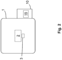
- Figure 1 is a method according to the invention for determining a synchronous speed n0 of an electrical machine 2, specifically and by way of example in the form of a speed-controlled asynchronous machine 2, at a speed generated by the asynchronous machine 2 driven machine 1 is schematically visualized with the associated process steps.
- a control device 3 can be provided for controlling the speed of the asynchronous machine 2.
- the control device 3 can be part of a system according to the invention together with the work machine 1 and/or the processing device 10 according to the invention.
- the asynchronous machine 2 and the control device 3 can be part of the work machine 1, whereas the processing device 10 can be designed as a mobile device separate from the work machine 1.
- a computer program according to the invention can be stored in a non-volatile manner in a memory 15 of the processing device 10 in order to be executed by a processor (not explicitly shown) of the processing device 10 to carry out the method steps of a method according to the invention.
- the aim of determining the synchronous speed n0 can be to determine an operating point of the working machine 1.
- the current synchronous speed n0 of the electrical machine 2 is required in a first step.
- an examination of a frequency spectrum in the case of a noise of the working machine 1 and/or electrical machine 2 can lead to the determination of the current synchronous speed.
- the magnetically excited acoustic noises in electrical machines 2 can have different causes, such as stator and rotor usage, stator and rotor saturation, a coupling between fundamental wave air gap fields, which is caused by the converter-related fundamental current and current harmonics supply, the type of converter supply, etc.
- stator and rotor usage it can be a problem that the electrical machine 2 is unknown, and therefore both the stator and rotor usage and the stator and rotor saturation are unknown. It is therefore advantageous to evaluate the vibration forces in order to determine the synchronous speed n0, which arise in the air gap as a result of the coupling between the fundamental wave rotating fields, which are generated by the converter-related fundamental current and current harmonics.
- the current harmonics can be determined by a type of converter supply.
- the method according to the invention can be suitable for determining the synchronous speed n0 in an electrical machine 2, which the asynchronous pulse width modulation (PWM) undershoot method with symmetrical triangle carrier signal is used.
- PWM pulse width modulation
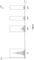
- FIG 5 is an exemplary frequency spectrum of a stator voltage of the electric machine 2 for an exemplary clock frequency fT of 4 kHz.
- the frequencies relevant for the method according to the invention are highlighted by a dashed rectangle, and in Figure 6 shown enlarged.
- the dashed rectangles around the clock frequency fT or the multiples thereof can also indicate possible windows for windowing.
- the amplitudes of the respective frequency bands also depend on the level of control (modulation index).
- n 1 is an odd integer
- n 2 is an even integer
- n 1 is an even integer
- n 2 is an odd integer
- f k f T ⁇ 2 ⁇ f S ; f T ⁇ 4 ⁇ f S ; ... 2 ⁇ f T ⁇ f s ; 2 ⁇ f T ⁇ 3 ⁇ f S ; 2 ⁇ f T ⁇ 5 ⁇ f s ; ... 3 ⁇ f T ⁇ 2 ⁇ f s ; 3 ⁇ f T ⁇ 4 ⁇ f S ; 3 ⁇ f T ⁇ 6 ⁇ f S ; ... etc.
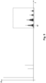
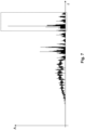
- FIG 7 A frequency spectrum 210 of a noise of the working machine 1 operated on a speed-controlled asynchronous machine 2 is shown as an example.
- the dashed rectangle indicates the frequencies relevant to the method according to the invention, which are excited by the harmonics of the frequency converter.
- An enlarged representation of these frequencies is shown schematically in Figure 8 shown.
- f k f T ⁇ f S ; f T ⁇ 3 ⁇ f S ; ...2 ⁇ f T ⁇ 2 ⁇ f S ; 2 ⁇ f T ⁇ 4 ⁇ fs; 2 ⁇ f T ⁇ 6 ⁇ f S ; ...3 ⁇ f T ⁇ 5 ⁇ f S ; 3 ⁇ f T ⁇ 7 ⁇ f S ; 3 ⁇ f T ⁇ 9 ⁇ f S ; ...etc .
- n0 f S p
- the method described in the document EP 2 433 010 B1 can be further applied to determine the operating point of the working machine 1.
- the accuracy can be further increased by analyzing or comparing the frequencies in several frequency windows.
- the Figures 7 and 8 The frequency spectrum shown can be evaluated using windowing and peak detection.
- the selection 103 may optionally include the implementation of a windowing of the frequency spectrum 210.
- a - in Figure 4 marked - window width fb can be determined based on a predefined expected synchronous speed n0.
- the minimum window width, which must be considered around the clock frequency and/or a multiple of the clock frequency of the control device 3, in particular a frequency converter 3, can be determined by ⁇ 2 ⁇ maximum expected fundamental frequency determine.
- the window position can then be determined based on the clock frequency fT.
- the window position corresponds to the clock frequency fT, so that the clock frequency can be understood as the center frequency of the frequency range 220.
- at least one windowing can be carried out, in which the window position corresponds to a multiple of the clock frequency fT, so that the multiple of the clock frequency fT can be understood as the center frequency of the frequency range 220.
- This area can then be cut out, ie a windowing of the frequency spectrum 210 can be carried out to select 103 the frequency range 220 as a range around the clock frequency fT with the specified window width fb and window position.
- the window width fb and the window position for the windowing can be determined (e.g.
- the subsequent detection 104 of the at least one peak value 230 or at least or exactly two peak values 230 in the frequency range 220 only detects such frequencies f1, f2 of the frequency range 220, which are specific to the synchronous speed n0 (see Figure 4 ).
- the amplitudes of the frequencies in the frequency range 220 can be compared with a threshold value in order to select the frequencies that exceed this threshold value as frequencies f1, f2 specific to the synchronous speed n0.
- the amplitudes A can be understood as peak values 230 that exceed the threshold value.
- the current synchronous speed n0 of the electric machine 2 can thus be determined by examining the frequency spectrum 210 in ranges around the multiple of the clock frequency fT.
- Possible clock frequencies can be, for example, 2 kHz, 4 kHz, 6 kHz, 8 kHz, 10 kHz, 12 kHz, 14 kHz or 16 kHz.
- the synchronous speed n0 can then be determined using a frequency difference between the determined frequencies f1, f2, for example as described above.
- the method can be EP 2 433 010 B1 can be further applied to determine the operating point of the driven machine.
- the current rotational speed n can be determined by means of conventional methods from the frequency spectrum of the detection information 200, in particular of a noise, shown in Figure 3.
- the working machine 1 can be reliably characterized using the nM characteristic curve, wherein the synchronous speed required for this purpose is determined by means of the method according to the invention.
Landscapes
- Engineering & Computer Science (AREA)
- Mechanical Engineering (AREA)
- General Engineering & Computer Science (AREA)
- Physics & Mathematics (AREA)
- General Physics & Mathematics (AREA)
- Power Engineering (AREA)
- Acoustics & Sound (AREA)
- Multimedia (AREA)
- Control Of Ac Motors In General (AREA)
- Control Of Electric Motors In General (AREA)
Priority Applications (1)
| Application Number | Priority Date | Filing Date | Title |
|---|---|---|---|
| RS20250262A RS66615B1 (sr) | 2020-08-18 | 2021-08-12 | Postupak za određivanje sinhrone brzine |
Applications Claiming Priority (2)
| Application Number | Priority Date | Filing Date | Title |
|---|---|---|---|
| DE102020005050.6A DE102020005050A1 (de) | 2020-08-18 | 2020-08-18 | Verfahren zur Bestimmung einer Synchrondrehzahl |
| PCT/EP2021/072446 WO2022038026A1 (de) | 2020-08-18 | 2021-08-12 | Verfahren zur bestimmung einer synchrondrehzahl |
Publications (3)
| Publication Number | Publication Date |
|---|---|
| EP4200971A1 EP4200971A1 (de) | 2023-06-28 |
| EP4200971C0 EP4200971C0 (de) | 2025-01-15 |
| EP4200971B1 true EP4200971B1 (de) | 2025-01-15 |
Family
ID=77520734
Family Applications (1)
| Application Number | Title | Priority Date | Filing Date |
|---|---|---|---|
| EP21762434.5A Active EP4200971B1 (de) | 2020-08-18 | 2021-08-12 | Verfahren zur bestimmung einer synchrondrehzahl |
Country Status (9)
| Country | Link |
|---|---|
| US (1) | US20240275320A1 (pl) |
| EP (1) | EP4200971B1 (pl) |
| CN (1) | CN115956268A (pl) |
| DE (1) | DE102020005050A1 (pl) |
| ES (1) | ES3019614T3 (pl) |
| HU (1) | HUE070753T2 (pl) |
| PL (1) | PL4200971T4 (pl) |
| RS (1) | RS66615B1 (pl) |
| WO (1) | WO2022038026A1 (pl) |
Families Citing this family (5)
| Publication number | Priority date | Publication date | Assignee | Title |
|---|---|---|---|---|
| DE102019125590A1 (de) * | 2019-09-24 | 2021-03-25 | Wirtgen Gmbh | Überwachungsvorrichtung für einen Gleitschalungsfertiger zur Überwachung der Verdichtung von Beton und Verfahren zur Überwachung der Verdichtung von Beton während des Betriebs eines Gleitschalungsfertigers |
| EP4361582B1 (de) * | 2022-10-24 | 2025-02-26 | Wilo Se | Verfahren zur zustandsuntersuchung bei einem pumpenaggregat sowie softwareapplikation, speichermedium und untersuchungsgerät zur ausführung des verfahrens |
| DE102022128744A1 (de) | 2022-10-28 | 2024-05-08 | KSB SE & Co. KGaA | Verfahren zum Informationsaustausch zwischen einem externen Empfänger und einer Pumpe |
| DE102024112831A1 (de) | 2023-06-13 | 2024-12-19 | Sew-Eurodrive Gmbh & Co Kg | System, aufweisend einen Elektromotor und einen Körperschallsensor |
| DE102023117624A1 (de) * | 2023-07-04 | 2025-01-09 | Danfoss Power Electronics A/S | Verfahren zur Berechnung der mechanischen Drehzahl einer elektrischen Rotationsmaschine |
Citations (1)
| Publication number | Priority date | Publication date | Assignee | Title |
|---|---|---|---|---|
| EP2433010B1 (de) * | 2009-05-20 | 2015-09-23 | KSB Aktiengesellschaft | Verfahren und vorrichtung zur betriebspunktbestimmung einer arbeitsmaschine |
Family Cites Families (4)
| Publication number | Priority date | Publication date | Assignee | Title |
|---|---|---|---|---|
| JP4650022B2 (ja) * | 2005-02-22 | 2011-03-16 | 株式会社デンソー | 回転速度検出装置 |
| CN104601074B (zh) * | 2015-02-25 | 2017-04-26 | 珠海派诺科技股份有限公司 | 一种基于均方根解调的电机转速测算方法 |
| DE102017213131A1 (de) * | 2017-07-31 | 2019-01-31 | Robert Bosch Gmbh | Verfahren und Steuergerät zum Steuern eines Aktuators eines Systems sowie derartiges System |
| JP7201413B2 (ja) * | 2018-11-30 | 2023-01-10 | 東芝産業機器システム株式会社 | 分析装置および分析プログラム |
-
2020
- 2020-08-18 DE DE102020005050.6A patent/DE102020005050A1/de active Pending
-
2021
- 2021-08-12 US US18/021,877 patent/US20240275320A1/en active Pending
- 2021-08-12 ES ES21762434T patent/ES3019614T3/es active Active
- 2021-08-12 CN CN202180050181.7A patent/CN115956268A/zh active Pending
- 2021-08-12 PL PL21762434.5T patent/PL4200971T4/pl unknown
- 2021-08-12 HU HUE21762434A patent/HUE070753T2/hu unknown
- 2021-08-12 EP EP21762434.5A patent/EP4200971B1/de active Active
- 2021-08-12 WO PCT/EP2021/072446 patent/WO2022038026A1/de not_active Ceased
- 2021-08-12 RS RS20250262A patent/RS66615B1/sr unknown
Patent Citations (1)
| Publication number | Priority date | Publication date | Assignee | Title |
|---|---|---|---|---|
| EP2433010B1 (de) * | 2009-05-20 | 2015-09-23 | KSB Aktiengesellschaft | Verfahren und vorrichtung zur betriebspunktbestimmung einer arbeitsmaschine |
Also Published As
| Publication number | Publication date |
|---|---|
| RS66615B1 (sr) | 2025-04-30 |
| US20240275320A1 (en) | 2024-08-15 |
| WO2022038026A1 (de) | 2022-02-24 |
| PL4200971T3 (pl) | 2025-05-26 |
| HUE070753T2 (hu) | 2025-07-28 |
| EP4200971A1 (de) | 2023-06-28 |
| CN115956268A (zh) | 2023-04-11 |
| EP4200971C0 (de) | 2025-01-15 |
| PL4200971T4 (pl) | 2025-05-26 |
| DE102020005050A1 (de) | 2022-02-24 |
| ES3019614T3 (en) | 2025-05-20 |
Similar Documents
| Publication | Publication Date | Title |
|---|---|---|
| EP4200971B1 (de) | Verfahren zur bestimmung einer synchrondrehzahl | |
| EP2433010B1 (de) | Verfahren und vorrichtung zur betriebspunktbestimmung einer arbeitsmaschine | |
| EP1109034B1 (de) | Verfahren und Einrichtung zur Untersuchung und Identifizierung der Art eines Untergrundes | |
| EP3370046B1 (de) | Verfahren und vorrichtung zur bestimmung von maschinendrehzahlen | |
| DE102014000477A1 (de) | Vorrichtung und Verfahren zum Messen von Befestigungskräften | |
| WO2020249313A1 (de) | Verfahren zur ermittlung des winkels des rotors eines elektromotors, steuergerät sowie fahrzeug | |
| EP2067249B1 (de) | Verfahren zum betreiben eines elektronisch kommutierenden elektromotors | |
| EP4172579B1 (de) | Verfahren für eine überwachung wenigstens einer durch eine rotierende maschine angetriebenen arbeitsmaschine | |
| DE102015105007A1 (de) | Verfahren zur sensorlosen Lagebestimmung des Rotors von elektronisch kommutierten Synchronmaschinen | |
| DE102005017073A1 (de) | Steuerverfahren für magnetisch bedingte Geräusche von rotierenden Wechselstrommaschinen | |
| DE102006008048B4 (de) | Motordrehzahlerfassungsvorrichtung | |
| EP3651347B1 (de) | Verfahren zum regeln eines permanentmagnetsynchronmotors, steuervorrichtung und vakuumgerät | |
| EP3729634B1 (de) | Verfahren zur drehgeberlosen rotorlagebestimmung einer drehfeldmaschine und vorrichtung zur drehgeberlosen regelung eines drehstrommotors | |
| EP2903153A1 (de) | Schwingungs- und Geräuschanalyse einer umrichtergespeisten elektrischen Maschine | |
| DE102006004034A1 (de) | Verfahren zum geberlosen Betrieb einer stromrichtergespeisten, permanenterregten Synchronmaschine mit einem Testsignal | |
| DE102016102635A1 (de) | Verfahren und Vorrichtung zum Bestimmen mindestens eines Maschinenparameters | |
| EP2982035B1 (de) | Verfahren zum anlaufen eines drehzahlveränderlichen elektromotors | |
| WO2023094352A1 (de) | Verfahren zur geräuschreduktion im betrieb eines elektromotors, sowie motorsteuervorrichtung zur steuerung des betriebs eines elektromotors mit geräuschreduktion | |
| DE102008022621A1 (de) | Verfahren zur Bestimmung der Position und/oder des Drehwinkels und/oder der Drehzahl eines elektrischen Antriebs | |
| EP1856792B2 (de) | Rotorlagendetektion | |
| EP3175545B1 (de) | Verfahren zur motorsteuerung eines synchron-reluktanzmotors für eine pumpe und pumpe mit synchron-reluktanzmotor | |
| EP3794724A1 (de) | Verfahren zum betreiben eines stromrichters, stromrichter für eine permanenterregte elektrische maschine, fahrzeug und computerprogrammprodukt | |
| EP3618266A1 (de) | Ermittlung einer drehzahl eines rotors durch schwingungsanalyse | |
| DE102023107259A1 (de) | Verfahren und Vorrichtung zur Überwachung von Phasenstromsensoren | |
| DE102022127452A1 (de) | Verfahren und system, um tonale geräusche über einen grossen drehzahlbereich in elektrischen wechselstrommaschinen zu unterdrücken |
Legal Events
| Date | Code | Title | Description |
|---|---|---|---|
| STAA | Information on the status of an ep patent application or granted ep patent |
Free format text: STATUS: UNKNOWN |
|
| STAA | Information on the status of an ep patent application or granted ep patent |
Free format text: STATUS: THE INTERNATIONAL PUBLICATION HAS BEEN MADE |
|
| PUAI | Public reference made under article 153(3) epc to a published international application that has entered the european phase |
Free format text: ORIGINAL CODE: 0009012 |
|
| STAA | Information on the status of an ep patent application or granted ep patent |
Free format text: STATUS: REQUEST FOR EXAMINATION WAS MADE |
|
| 17P | Request for examination filed |
Effective date: 20230127 |
|
| AK | Designated contracting states |
Kind code of ref document: A1 Designated state(s): AL AT BE BG CH CY CZ DE DK EE ES FI FR GB GR HR HU IE IS IT LI LT LU LV MC MK MT NL NO PL PT RO RS SE SI SK SM TR |
|
| DAV | Request for validation of the european patent (deleted) | ||
| DAX | Request for extension of the european patent (deleted) | ||
| REG | Reference to a national code |
Ref country code: DE Ref legal event code: R079 Free format text: PREVIOUS MAIN CLASS: H02P0023140000 Ipc: F04D0013060000 Ref country code: DE Ref legal event code: R079 Ref document number: 502021006449 Country of ref document: DE Free format text: PREVIOUS MAIN CLASS: H02P0023140000 Ipc: F04D0013060000 |
|
| RIC1 | Information provided on ipc code assigned before grant |
Ipc: H02P 23/14 20060101ALI20240311BHEP Ipc: G10K 11/16 20060101ALI20240311BHEP Ipc: F04D 15/00 20060101ALI20240311BHEP Ipc: G01H 3/08 20060101ALI20240311BHEP Ipc: G01H 1/00 20060101ALI20240311BHEP Ipc: F04D 13/06 20060101AFI20240311BHEP |
|
| GRAP | Despatch of communication of intention to grant a patent |
Free format text: ORIGINAL CODE: EPIDOSNIGR1 |
|
| STAA | Information on the status of an ep patent application or granted ep patent |
Free format text: STATUS: GRANT OF PATENT IS INTENDED |
|
| INTG | Intention to grant announced |
Effective date: 20240424 |
|
| GRAS | Grant fee paid |
Free format text: ORIGINAL CODE: EPIDOSNIGR3 |
|
| GRAJ | Information related to disapproval of communication of intention to grant by the applicant or resumption of examination proceedings by the epo deleted |
Free format text: ORIGINAL CODE: EPIDOSDIGR1 |
|
| GRAL | Information related to payment of fee for publishing/printing deleted |
Free format text: ORIGINAL CODE: EPIDOSDIGR3 |
|
| STAA | Information on the status of an ep patent application or granted ep patent |
Free format text: STATUS: REQUEST FOR EXAMINATION WAS MADE |
|
| GRAP | Despatch of communication of intention to grant a patent |
Free format text: ORIGINAL CODE: EPIDOSNIGR1 |
|
| STAA | Information on the status of an ep patent application or granted ep patent |
Free format text: STATUS: GRANT OF PATENT IS INTENDED |
|
| INTC | Intention to grant announced (deleted) | ||
| INTG | Intention to grant announced |
Effective date: 20240912 |
|
| GRAA | (expected) grant |
Free format text: ORIGINAL CODE: 0009210 |
|
| STAA | Information on the status of an ep patent application or granted ep patent |
Free format text: STATUS: THE PATENT HAS BEEN GRANTED |
|
| AK | Designated contracting states |
Kind code of ref document: B1 Designated state(s): AL AT BE BG CH CY CZ DE DK EE ES FI FR GB GR HR HU IE IS IT LI LT LU LV MC MK MT NL NO PL PT RO RS SE SI SK SM TR |
|
| REG | Reference to a national code |
Ref country code: CH Ref legal event code: EP Ref country code: GB Ref legal event code: FG4D Free format text: NOT ENGLISH |
|
| REG | Reference to a national code |
Ref country code: DE Ref legal event code: R096 Ref document number: 502021006449 Country of ref document: DE |
|
| REG | Reference to a national code |
Ref country code: IE Ref legal event code: FG4D Free format text: LANGUAGE OF EP DOCUMENT: GERMAN |
|
| U01 | Request for unitary effect filed |
Effective date: 20250131 |
|
| U07 | Unitary effect registered |
Designated state(s): AT BE BG DE DK EE FI FR IT LT LU LV MT NL PT RO SE SI Effective date: 20250207 |
|
| REG | Reference to a national code |
Ref country code: ES Ref legal event code: FG2A Ref document number: 3019614 Country of ref document: ES Kind code of ref document: T3 Effective date: 20250520 |
|
| PG25 | Lapsed in a contracting state [announced via postgrant information from national office to epo] |
Ref country code: IS Free format text: LAPSE BECAUSE OF FAILURE TO SUBMIT A TRANSLATION OF THE DESCRIPTION OR TO PAY THE FEE WITHIN THE PRESCRIBED TIME-LIMIT Effective date: 20250515 |
|
| PG25 | Lapsed in a contracting state [announced via postgrant information from national office to epo] |
Ref country code: HR Free format text: LAPSE BECAUSE OF FAILURE TO SUBMIT A TRANSLATION OF THE DESCRIPTION OR TO PAY THE FEE WITHIN THE PRESCRIBED TIME-LIMIT Effective date: 20250115 |
|
| PG25 | Lapsed in a contracting state [announced via postgrant information from national office to epo] |
Ref country code: GR Free format text: LAPSE BECAUSE OF FAILURE TO SUBMIT A TRANSLATION OF THE DESCRIPTION OR TO PAY THE FEE WITHIN THE PRESCRIBED TIME-LIMIT Effective date: 20250416 |
|
| REG | Reference to a national code |
Ref country code: HU Ref legal event code: AG4A Ref document number: E070753 Country of ref document: HU |
|
| PGFP | Annual fee paid to national office [announced via postgrant information from national office to epo] |
Ref country code: HU Payment date: 20250725 Year of fee payment: 5 |
|
| U20 | Renewal fee for the european patent with unitary effect paid |
Year of fee payment: 5 Effective date: 20250826 |
|
| PG25 | Lapsed in a contracting state [announced via postgrant information from national office to epo] |
Ref country code: SM Free format text: LAPSE BECAUSE OF FAILURE TO SUBMIT A TRANSLATION OF THE DESCRIPTION OR TO PAY THE FEE WITHIN THE PRESCRIBED TIME-LIMIT Effective date: 20250115 |
|
| PGFP | Annual fee paid to national office [announced via postgrant information from national office to epo] |
Ref country code: ES Payment date: 20250902 Year of fee payment: 5 |
|
| PGFP | Annual fee paid to national office [announced via postgrant information from national office to epo] |
Ref country code: NO Payment date: 20250829 Year of fee payment: 5 |
|
| PGFP | Annual fee paid to national office [announced via postgrant information from national office to epo] |
Ref country code: TR Payment date: 20250729 Year of fee payment: 5 Ref country code: PL Payment date: 20250721 Year of fee payment: 5 |
|
| PGFP | Annual fee paid to national office [announced via postgrant information from national office to epo] |
Ref country code: GB Payment date: 20250827 Year of fee payment: 5 |
|
| PGFP | Annual fee paid to national office [announced via postgrant information from national office to epo] |
Ref country code: CH Payment date: 20250901 Year of fee payment: 5 |
|
| PGFP | Annual fee paid to national office [announced via postgrant information from national office to epo] |
Ref country code: IE Payment date: 20250824 Year of fee payment: 5 Ref country code: RS Payment date: 20250718 Year of fee payment: 5 Ref country code: CZ Payment date: 20250718 Year of fee payment: 5 |
|
| PG25 | Lapsed in a contracting state [announced via postgrant information from national office to epo] |
Ref country code: SK Free format text: LAPSE BECAUSE OF FAILURE TO SUBMIT A TRANSLATION OF THE DESCRIPTION OR TO PAY THE FEE WITHIN THE PRESCRIBED TIME-LIMIT Effective date: 20250115 |
|
| PLBE | No opposition filed within time limit |
Free format text: ORIGINAL CODE: 0009261 |
|
| STAA | Information on the status of an ep patent application or granted ep patent |
Free format text: STATUS: NO OPPOSITION FILED WITHIN TIME LIMIT |