EP4200535B1 - Unité et procédé de direction de dispositif de rétroaction tactile de tambour - Google Patents
Unité et procédé de direction de dispositif de rétroaction tactile de tambour Download PDFInfo
- Publication number
- EP4200535B1 EP4200535B1 EP21881156.0A EP21881156A EP4200535B1 EP 4200535 B1 EP4200535 B1 EP 4200535B1 EP 21881156 A EP21881156 A EP 21881156A EP 4200535 B1 EP4200535 B1 EP 4200535B1
- Authority
- EP
- European Patent Office
- Prior art keywords
- drum
- gap
- brake
- tfd
- housing
- Prior art date
- Legal status (The legal status is an assumption and is not a legal conclusion. Google has not performed a legal analysis and makes no representation as to the accuracy of the status listed.)
- Active
Links
Images


Classifications
-
- B—PERFORMING OPERATIONS; TRANSPORTING
- B62—LAND VEHICLES FOR TRAVELLING OTHERWISE THAN ON RAILS
- B62D—MOTOR VEHICLES; TRAILERS
- B62D5/00—Power-assisted or power-driven steering
- B62D5/001—Mechanical components or aspects of steer-by-wire systems, not otherwise provided for in this maingroup
- B62D5/005—Mechanical components or aspects of steer-by-wire systems, not otherwise provided for in this maingroup means for generating torque on steering wheel or input member, e.g. feedback
-
- F—MECHANICAL ENGINEERING; LIGHTING; HEATING; WEAPONS; BLASTING
- F16—ENGINEERING ELEMENTS AND UNITS; GENERAL MEASURES FOR PRODUCING AND MAINTAINING EFFECTIVE FUNCTIONING OF MACHINES OR INSTALLATIONS; THERMAL INSULATION IN GENERAL
- F16D—COUPLINGS FOR TRANSMITTING ROTATION; CLUTCHES; BRAKES
- F16D57/00—Liquid-resistance brakes; Brakes using the internal friction of fluids or fluid-like media, e.g. powders
- F16D57/002—Liquid-resistance brakes; Brakes using the internal friction of fluids or fluid-like media, e.g. powders comprising a medium with electrically or magnetically controlled internal friction, e.g. electrorheological fluid, magnetic powder
-
- F—MECHANICAL ENGINEERING; LIGHTING; HEATING; WEAPONS; BLASTING
- F16—ENGINEERING ELEMENTS AND UNITS; GENERAL MEASURES FOR PRODUCING AND MAINTAINING EFFECTIVE FUNCTIONING OF MACHINES OR INSTALLATIONS; THERMAL INSULATION IN GENERAL
- F16D—COUPLINGS FOR TRANSMITTING ROTATION; CLUTCHES; BRAKES
- F16D57/00—Liquid-resistance brakes; Brakes using the internal friction of fluids or fluid-like media, e.g. powders
- F16D57/02—Liquid-resistance brakes; Brakes using the internal friction of fluids or fluid-like media, e.g. powders with blades or like members braked by the fluid
-
- F—MECHANICAL ENGINEERING; LIGHTING; HEATING; WEAPONS; BLASTING
- F16—ENGINEERING ELEMENTS AND UNITS; GENERAL MEASURES FOR PRODUCING AND MAINTAINING EFFECTIVE FUNCTIONING OF MACHINES OR INSTALLATIONS; THERMAL INSULATION IN GENERAL
- F16F—SPRINGS; SHOCK-ABSORBERS; MEANS FOR DAMPING VIBRATION
- F16F15/00—Suppression of vibrations in systems; Means or arrangements for avoiding or reducing out-of-balance forces, e.g. due to motion
- F16F15/005—Suppression of vibrations in systems; Means or arrangements for avoiding or reducing out-of-balance forces, e.g. due to motion using electro- or magnetostrictive actuation means
-
- F—MECHANICAL ENGINEERING; LIGHTING; HEATING; WEAPONS; BLASTING
- F16—ENGINEERING ELEMENTS AND UNITS; GENERAL MEASURES FOR PRODUCING AND MAINTAINING EFFECTIVE FUNCTIONING OF MACHINES OR INSTALLATIONS; THERMAL INSULATION IN GENERAL
- F16F—SPRINGS; SHOCK-ABSORBERS; MEANS FOR DAMPING VIBRATION
- F16F9/00—Springs, vibration-dampers, shock-absorbers, or similarly-constructed movement-dampers using a fluid or the equivalent as damping medium
- F16F9/006—Springs, vibration-dampers, shock-absorbers, or similarly-constructed movement-dampers using a fluid or the equivalent as damping medium characterised by the nature of the damping medium, e.g. biodegradable
-
- F—MECHANICAL ENGINEERING; LIGHTING; HEATING; WEAPONS; BLASTING
- F16—ENGINEERING ELEMENTS AND UNITS; GENERAL MEASURES FOR PRODUCING AND MAINTAINING EFFECTIVE FUNCTIONING OF MACHINES OR INSTALLATIONS; THERMAL INSULATION IN GENERAL
- F16F—SPRINGS; SHOCK-ABSORBERS; MEANS FOR DAMPING VIBRATION
- F16F9/00—Springs, vibration-dampers, shock-absorbers, or similarly-constructed movement-dampers using a fluid or the equivalent as damping medium
- F16F9/30—Springs, vibration-dampers, shock-absorbers, or similarly-constructed movement-dampers using a fluid or the equivalent as damping medium with solid or semi-solid material, e.g. pasty masses, as damping medium
-
- F—MECHANICAL ENGINEERING; LIGHTING; HEATING; WEAPONS; BLASTING
- F16—ENGINEERING ELEMENTS AND UNITS; GENERAL MEASURES FOR PRODUCING AND MAINTAINING EFFECTIVE FUNCTIONING OF MACHINES OR INSTALLATIONS; THERMAL INSULATION IN GENERAL
- F16F—SPRINGS; SHOCK-ABSORBERS; MEANS FOR DAMPING VIBRATION
- F16F9/00—Springs, vibration-dampers, shock-absorbers, or similarly-constructed movement-dampers using a fluid or the equivalent as damping medium
- F16F9/32—Details
- F16F9/53—Means for adjusting damping characteristics by varying fluid viscosity, e.g. electromagnetically
- F16F9/535—Magnetorheological [MR] fluid dampers
-
- G—PHYSICS
- G05—CONTROLLING; REGULATING
- G05G—CONTROL DEVICES OR SYSTEMS INSOFAR AS CHARACTERISED BY MECHANICAL FEATURES ONLY
- G05G5/00—Means for preventing, limiting or returning the movements of parts of a control mechanism, e.g. locking controlling member
- G05G5/03—Means for enhancing the operator's awareness of arrival of the controlling member at a command or datum position; Providing feel, e.g. means for creating a counterforce
-
- H—ELECTRICITY
- H02—GENERATION; CONVERSION OR DISTRIBUTION OF ELECTRIC POWER
- H02K—DYNAMO-ELECTRIC MACHINES
- H02K1/00—Details of the magnetic circuit
- H02K1/06—Details of the magnetic circuit characterised by the shape, form or construction
- H02K1/22—Rotating parts of the magnetic circuit
-
- H—ELECTRICITY
- H02—GENERATION; CONVERSION OR DISTRIBUTION OF ELECTRIC POWER
- H02K—DYNAMO-ELECTRIC MACHINES
- H02K11/00—Structural association of dynamo-electric machines with electric components or with devices for shielding, monitoring or protection
- H02K11/20—Structural association of dynamo-electric machines with electric components or with devices for shielding, monitoring or protection for measuring, monitoring, testing, protecting or switching
- H02K11/21—Devices for sensing speed or position, or actuated thereby
-
- H—ELECTRICITY
- H02—GENERATION; CONVERSION OR DISTRIBUTION OF ELECTRIC POWER
- H02K—DYNAMO-ELECTRIC MACHINES
- H02K7/00—Arrangements for handling mechanical energy structurally associated with dynamo-electric machines, e.g. structural association with mechanical driving motors or auxiliary dynamo-electric machines
- H02K7/003—Couplings; Details of shafts
-
- H—ELECTRICITY
- H02—GENERATION; CONVERSION OR DISTRIBUTION OF ELECTRIC POWER
- H02K—DYNAMO-ELECTRIC MACHINES
- H02K7/00—Arrangements for handling mechanical energy structurally associated with dynamo-electric machines, e.g. structural association with mechanical driving motors or auxiliary dynamo-electric machines
- H02K7/10—Structural association with clutches, brakes, gears, pulleys or mechanical starters
-
- B—PERFORMING OPERATIONS; TRANSPORTING
- B62—LAND VEHICLES FOR TRAVELLING OTHERWISE THAN ON RAILS
- B62D—MOTOR VEHICLES; TRAILERS
- B62D5/00—Power-assisted or power-driven steering
- B62D5/001—Mechanical components or aspects of steer-by-wire systems, not otherwise provided for in this maingroup
- B62D5/005—Mechanical components or aspects of steer-by-wire systems, not otherwise provided for in this maingroup means for generating torque on steering wheel or input member, e.g. feedback
- B62D5/006—Mechanical components or aspects of steer-by-wire systems, not otherwise provided for in this maingroup means for generating torque on steering wheel or input member, e.g. feedback power actuated
-
- F—MECHANICAL ENGINEERING; LIGHTING; HEATING; WEAPONS; BLASTING
- F16—ENGINEERING ELEMENTS AND UNITS; GENERAL MEASURES FOR PRODUCING AND MAINTAINING EFFECTIVE FUNCTIONING OF MACHINES OR INSTALLATIONS; THERMAL INSULATION IN GENERAL
- F16D—COUPLINGS FOR TRANSMITTING ROTATION; CLUTCHES; BRAKES
- F16D2121/00—Type of actuator operation force
- F16D2121/18—Electric or magnetic
- F16D2121/20—Electric or magnetic using electromagnets
-
- F—MECHANICAL ENGINEERING; LIGHTING; HEATING; WEAPONS; BLASTING
- F16—ENGINEERING ELEMENTS AND UNITS; GENERAL MEASURES FOR PRODUCING AND MAINTAINING EFFECTIVE FUNCTIONING OF MACHINES OR INSTALLATIONS; THERMAL INSULATION IN GENERAL
- F16D—COUPLINGS FOR TRANSMITTING ROTATION; CLUTCHES; BRAKES
- F16D2129/00—Type of operation source for auxiliary mechanisms
- F16D2129/06—Electric or magnetic
- F16D2129/08—Electromagnets
-
- F—MECHANICAL ENGINEERING; LIGHTING; HEATING; WEAPONS; BLASTING
- F16—ENGINEERING ELEMENTS AND UNITS; GENERAL MEASURES FOR PRODUCING AND MAINTAINING EFFECTIVE FUNCTIONING OF MACHINES OR INSTALLATIONS; THERMAL INSULATION IN GENERAL
- F16D—COUPLINGS FOR TRANSMITTING ROTATION; CLUTCHES; BRAKES
- F16D2200/00—Materials; Production methods therefor
- F16D2200/0034—Materials; Production methods therefor non-metallic
-
- F—MECHANICAL ENGINEERING; LIGHTING; HEATING; WEAPONS; BLASTING
- F16—ENGINEERING ELEMENTS AND UNITS; GENERAL MEASURES FOR PRODUCING AND MAINTAINING EFFECTIVE FUNCTIONING OF MACHINES OR INSTALLATIONS; THERMAL INSULATION IN GENERAL
- F16D—COUPLINGS FOR TRANSMITTING ROTATION; CLUTCHES; BRAKES
- F16D63/00—Brakes not otherwise provided for; Brakes combining more than one of the types of groups F16D49/00 - F16D61/00
- F16D63/002—Brakes with direct electrical or electro-magnetic actuation
-
- F—MECHANICAL ENGINEERING; LIGHTING; HEATING; WEAPONS; BLASTING
- F16—ENGINEERING ELEMENTS AND UNITS; GENERAL MEASURES FOR PRODUCING AND MAINTAINING EFFECTIVE FUNCTIONING OF MACHINES OR INSTALLATIONS; THERMAL INSULATION IN GENERAL
- F16F—SPRINGS; SHOCK-ABSORBERS; MEANS FOR DAMPING VIBRATION
- F16F2224/00—Materials; Material properties
- F16F2224/02—Materials; Material properties solids
-
- F—MECHANICAL ENGINEERING; LIGHTING; HEATING; WEAPONS; BLASTING
- F16—ENGINEERING ELEMENTS AND UNITS; GENERAL MEASURES FOR PRODUCING AND MAINTAINING EFFECTIVE FUNCTIONING OF MACHINES OR INSTALLATIONS; THERMAL INSULATION IN GENERAL
- F16F—SPRINGS; SHOCK-ABSORBERS; MEANS FOR DAMPING VIBRATION
- F16F2232/00—Nature of movement
- F16F2232/02—Rotary
-
- F—MECHANICAL ENGINEERING; LIGHTING; HEATING; WEAPONS; BLASTING
- F16—ENGINEERING ELEMENTS AND UNITS; GENERAL MEASURES FOR PRODUCING AND MAINTAINING EFFECTIVE FUNCTIONING OF MACHINES OR INSTALLATIONS; THERMAL INSULATION IN GENERAL
- F16F—SPRINGS; SHOCK-ABSORBERS; MEANS FOR DAMPING VIBRATION
- F16F9/00—Springs, vibration-dampers, shock-absorbers, or similarly-constructed movement-dampers using a fluid or the equivalent as damping medium
- F16F9/32—Details
- F16F9/53—Means for adjusting damping characteristics by varying fluid viscosity, e.g. electromagnetically
-
- G—PHYSICS
- G05—CONTROLLING; REGULATING
- G05G—CONTROL DEVICES OR SYSTEMS INSOFAR AS CHARACTERISED BY MECHANICAL FEATURES ONLY
- G05G2505/00—Means for preventing, limiting or returning the movements of parts of a control mechanism, e.g. locking controlling member
Definitions
- the subject matter herein generally relates to the field of resistive torque-generating devices and systems (e.g., brakes, locks, clutches, tactile feedback devices, resistance-generating devices, motion control devices, and the like). More particularly, the subject matter herein relates to tactile feedback device (TFD) drum brakes using magnetically responsive (MR) material to generate resistive torque.
- resistive torque-generating devices and systems e.g., brakes, locks, clutches, tactile feedback devices, resistance-generating devices, motion control devices, and the like. More particularly, the subject matter herein relates to tactile feedback device (TFD) drum brakes using magnetically responsive (MR) material to generate resistive torque.
- MR magnetically responsive
- MR magnetically responsive
- a tactile feedback device drum brake comprising a shaft having a rotation disk rotatably connected thereto a drum rotor connected to the rotation disk, a core (5) having an integrated coil positioned radially inward from the drum rotor forming a first gap therebetween, a pole ring fixedly positioned radially outward from the drum rotor forming a second gap therebetween and a magnetically responsive material disposed within the first gap and the second gap.
- a tactile feedback device (TFD) drum brake comprises a shaft, a drum rotor, a core, a pole ring, a magnetically responsive (MR) material, an upper magnetic seal, a lower magnetic seal, at least one sensor, and a housing enclosing the foregoing.
- the shaft has a rotation disk rotatably connected thereto.
- the drum rotor is connected to the rotation disk.
- the core has an integrated coil positioned radially inward from the drum rotor and forms a first gap therebetween.
- the pole ring is fixedly positioned radially outward from the drum rotor and forms a second gap therebetween.
- the MR material is disposed within the first gap and the second gap.
- the upper magnetic seal is positioned to block MR material from moving from the second gap.
- the lower magnetic seal is positioned to block MR material from moving from the first gap.
- the housing encloses the shaft, the drum rotor, the core, the upper magnetic seal, and the lower magnetic seal.
- the housing has a housing cap and a sensor housing secured thereto. The at least one sensor is capable of detecting rotation of the shaft.
- the drum rotor has a first brake shear surface and a second brake shear surface, wherein the first brake shear surface is on a rotor inner surface (RIS) of the drum rotor and the second brake shear surface is on a rotor outer surface (ROS) of the drum rotor.
- the pole ring has a pole ring shear surface on a pole ring inner surface (PRIS) fixedly and oppositely positioned from the ROS, wherein a second gap is positioned between the PRIS and the ROS.
- the core has an integrated coil.
- the core has a core shear surface on a core outer surface (COS) oppositely positioned from the RIS, wherein a first gap is positioned between the COS and the RIS.
- COS core outer surface
- the rotation disk has an end, wherein the drum rotor is connected to the end and the rotation disk is rotatably connected to a shaft.
- the MR material is disposed within the first gap and the second gap.
- the housing includes a housing cap secured to a housing wall at housing top edge of the housing wall.
- the housing also includes a sensor housing secured to the housing wall at a housing bottom edge of the housing wall.
- the upper magnetic seal is positioned to block movement of the MR material from the first gap past an upper void between the upper magnetic seal and the housing cap.
- the lower magnetic seal is positioned to block movement of the MR material from the second gap past a lower void between lower magnetic seal and the core.
- a method according to claim 15 of providing tactile feedback using TFD drum brake according to claim 1 comprises generating torque with TFD drum brake, energizing an integrated coil by applying current to the integrated coil, magnetically saturating a drum rotor, and generating a resistive torque.
- the drum brake includes a housing which encloses a shaft, a drum rotor, a pole ring, a core, a rotation disk, an upper magnetic seal, a lower magnetic seal, a MR material, and at least one sensor.
- the drum rotor has a first brake shear surface and a second brake shear surface.
- the first brake shear surface is on a rotor inner surface (RIS) of the drum rotor and the second brake shear surface is on a rotor outer surface (ROS) of the drum rotor.
- the pole ring has a pole ring shear surface on the pole ring inner surface (PRIS) fixedly and oppositely positioned from the ROS.
- the second gap is positioned between the PRIS and the ROS.
- the core has the integrated coil and a core shear surface on core outer surface (COS) that is oppositely positioned from RIS.
- the first gap is positioned between the COS and RIS.
- the rotation disk has an end.
- the drum rotor is connected to the end and the rotation disk is rotatably connected to the shaft.
- the MR material is disposed within the first gap and the second gap.
- the housing includes a housing cap secured to the housing wall at a housing top edge of the housing wall.
- the housing also includes a sensor housing secured to the housing wall at a housing bottom edge
- the upper magnetic seal is positioned to block movement of MR material from the first gap past an upper void between the upper magnetic seal and the housing cap.
- the lower magnetic seal is positioned to block movement of the MR material from the second gap past lower void between the lower magnetic seal and the core.
- the TFD drum brake is controlled by a controller.
- the controller is in electronic communication with the at least one sensor.
- a power source generates a current.
- the power source is in electrical communication with the integrated coil.
- the controller is capable of controlling the current from the power source and the magnetic flux is generated as a result of the current being communicated to the integrated coil.
- a circuit is provided that is capable of saturating the drum rotor with the magnetic flux.
- the circuit includes the core, the first gap with the MR material disposed therein, the drum rotor, the second gap with the MR material disposed therein, and the pole ring.
- the drum rotor saturates when the magnetic flux passes through the circuit and when the magnetic flux reaches a threshold of about 1.3 Tesla (T).
- the method step of energizing the integrated coil by applying current to the integrated coil generates the magnetic flux.
- the method step of magnetically saturating the drum rotor occurs with the generation of the magnetic flux.
- the step of magnetically saturating the drum rotor causes the first brake shear surface and the second brake shear surface of the drum rotor to shear against the MR material and each of the pole ring shear surface and the core shear surface.
- the method step of generating the resistive torque includes the shearing of the MR material against the first brake shear surface, the second brake shear surface, the pole ring shear surface, and the core shear surface to create the resistive torque.
- TFD tactile feedback device
- a typical magnetically responsive (MR) disk brake or a typical drum brake do not provide for radial compactness.
- a TFD drum brake as disclosed herein provides the benefits of a drum brake, but also adds a substantially increased torque provided by the MR material disposed within the TFD drum brake.
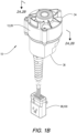
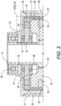
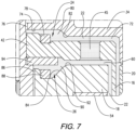
- Shaft 14 is rotatably disposed within housing 12. Shaft 14 is rotatably supported by upper bearings 38 and lower bearings 40. Shaft 14 has rotation disk 42 attached thereto and extending radially outward therefrom. Drum rotor 16 is connected to rotation disk 42 at end 44 of rotation disk 42 and rotates with shaft 14. As illustrated in FIGS. 1-3 drum rotor 16 extends radially outward from end 44 and is perpendicular to shaft 14 before it bends parallel to shaft 14 and perpendicular to rotation disk 42. It is understood that rotation disk 42 can extend radially outward and drum rotor 16 can only be parallel to shaft 14. Additionally, drum rotor 16 and rotational disk 42 can be a single component directly affixed to shaft 14. In one embodiment, drum rotor 16 has a thickness between about 0.5 millimeters to about 5 millimeters. In another embodiment, drum rotor 16 has a thickness of about 0.5 millimeters to about 1.5 millimeters.
- First brake shear surface 46 is on rotor inner surface (RIS) 48 of drum rotor 16, and second brake shear surface 50 that is on rotor outer surface (ROS) 52 on drum rotor 16.
- RIS 48 faces radially inward and ROS 52 faces radially outward.
- Core 18 is disposed about shaft 14 and is not rotatable relative to shaft 14. Core 18 is positioned radially inward from drum rotor 16. Core 18 includes integrated coil 54. Core 18 has core shear surface 56 on core outer surface (COS) 58 that is radially inward and oppositely positioned from RIS 48. The space between COS 58 and RIS 48 forms first gap 60 therebetween. MR material 22 is disposed within first gap 60.
- COS core outer surface
- Pole ring 20 is positioned and secured radially outward from drum rotor 16 and is secured between cap lower edge 62, lower seat 64 of housing wall 28, and wall inner surface 66. Pole ring 20 is fixedly positioned radially outward from drum rotor 16. Pole ring 20 has pole ring shear surface 68 on pole ring inner surface (PRIS) 70. PRIS 70 is radially outward and oppositely positioned from ROS 52. The space between ROS 52 and PRIS 70 forms second gap 72 therebetween. MR material 22 is also disposed within second gap 72. Flow hole 45 is positioned proximate end 44 and is part of rotation disk 42. Flow hole 45 allows for MR material 22 to flow between first gap 60 and second gap 72.
- PRIS pole ring inner surface
- first gap 60 and second gap 72 each have a width of about 0.5 millimeters to about 2.0 millimeters. In another embodiment, first gap 60 and second gap 72 each have a width of about 0.5 millimeters to about 1.0 millimeters.
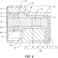
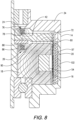
- upper magnetic seal 24 is positioned between second gap 72, rotation disk 42, and lower edge 74 of housing cap 34, where upper void 76 is formed therebetween. Upper magnetic seal 24 is positioned to prevent or block MR material 22 from moving from second gap 72. Upper magnetic seal 24 includes permanent magnet 78. Permanent magnet 78 is affixed to and rotates with rotation disk 42. Upper opening 80 is positioned between upper void edge 82 of second gap 72 and permanent magnet 78. Upper magnetic seal 24 prevents MR material 22 from entering upper void 76 through upper opening 80 and contaminating upper bearings 38.
- Lower magnetic seal 26 is positioned between first gap 60, rotation disk 42, and upper edge 84 of core 18, where lower void 86 is formed therebetween.
- Lower magnetic seal 26 includes second permanent magnet 88.
- Lower magnetic seal 26 is positioned to prevent or block MR material 22 from moving from first gap 60.
- Second permanent magnet 88 is affixed to and rotates with rotation disk 42.
- Lower opening 90 is positioned between lower void edge 92 of first gap 60 and second permanent magnet 88.
- Lower magnetic seal 26 prevents MR material 22 from entering lower void 86 and contaminating lower bearings 40.
- lower magnetic seal 26 is positioned affixed adjacent core 18 with second permanent magnet 88 affixed to core 18.
- Lower void 86 is positioned between non-magnetic washer 94 and lower opening 90.
- Non-magnetic washer 94 is positioned affixed to and rotates with rotation disk 42.
- polarity 95 of lower magnetic seal 26 in all embodiments is opposite of polarity 97 of pole ring 20.
- Rotation disk 42 provides the magnetic flux path for both upper magnetic seal 24 and lower magnetic seal 26.
- MR material 22 is a dry magnetically responsive powder including magnetizable particles that are not dispersed within a liquid or oil carrier.
- the magnetizable particles of material may include carbonyl iron, stainless steel, and/or any other magnetic material having various shapes, not limited to a spherical shape.
- MR material 22 is configured to provide smooth torque that is proportional to current, and it is independent of temperature.
- controller 98 and power source 100 are included with TFD drum brake 10.
- Power source 100 is capable of generating a current (not shown) and directly or indirectly electrically communicates the current to integrated coil 54.
- Power source 100 is externally positioned from TFD drum brake 10.
- Controller 98 is at least in electronic communication with at least one sensor 96, integrated coil 54, and power source 100.
- Controller may include a current amplifier (not shown) and at least one temperature sensor (not shown).
- Controller 98 is capable of controlling the current from power source 100 used to energize integrated coil 54 and generate magnetic flux 102.
- the control is provided by using algorithms related to end-stop torque to simulate the end of travel or to torque for creating the tactile feedback based upon inputs such as steering effort, vehicle speed, and other operating functions.
- the control also includes processing data at least from sensor 96 related to the rotation of shaft 14.
- Controller 98 increases or decreases the current from power source 100 that is electrically communicated to integrated coil 54.
- the current is controlled by the current amplifier, and it is capable of increasing or decreasing the current electrically communicated to integrated coil 54.
- the current amplifier is used when controller 98 is integrally positioned within sensor housing 36 of TFD drum brake 10.
- the current amplifier may be used when controller 98 is externally positioned from sensor housing 36 of TFD drum brake 10.
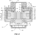
- magnetic flux 102 is generated when integrated coil 54 is energized with the current.
- Circuit 104 includes core 18, first gap 60 with MR material 22 disposed therein, drum rotor 16, second gap 72 with MR material 22 disposed therein, and pole ring 20.
- Magnetic flux 102 passes through circuit 104 and saturates drum rotor 16.
- controller 98 is capable of saturating drum rotor 16 with magnetic flux 102 generated by applying the current to integrated coil 54.
- Magnetic flux 102 causes the MR material 22 to create shear between the core shear surface 56 and the first brake shear surface 46, and between second brake shear surface 50 and pole ring shear surface 68. The effect of shearing due to is the creation of torque in TFD drum brake 10.
- TFD drum brake 10 may be used on a vehicle (not shown).
- Vehicles typically have a steering column (not shown) and a steering wheel (not shown) to enable steering the vehicle.
- TFD drum brake 10 enclosed therein.
- Shaft 15 of TFD drum brake 10 is capable of transmitting a feedback force to the operator through the steering wheel.
- a method of providing tactile feedback using TFD drum brake 10 comprises generating torque with TFD drum brake 10 described above, energizing integrated coil 54 by applying current to integrated coil 54, magnetically saturating drum rotor 16, and generating a resistive torque.
- the drum brake is described above and includes housing 12 which encloses shaft 14, drum rotor 16, pole ring 20, core 18, rotation disk 42, upper magnetic seal 24, lower magnetic seal 26, MR material 22, and at least one sensor 96.
- Drum rotor 16 has first brake shear surface 46 and second brake shear surface 50.
- First brake shear surface 46 is on rotor inner surface (RIS) 48 of drum rotor 16 and second brake shear surface 50 is on rotor outer surface (ROS) 52 of drum rotor 16.
- Pole ring 20 has pole ring shear surface 68 on pole ring inner surface (PRIS) 70 fixedly and oppositely positioned from ROS 52.
- Second gap 72 is positioned between PRIS 70 and ROS 52.
- Core 18 has integrated coil 54 and core shear surface 56 on core outer surface (COS) 58 oppositely positioned from RIS 48.
- First gap 60 is positioned between the COS (58) and RIS 48.
- Rotation disk 42 has end 44.
- Drum rotor 16 is connected to end 44 and rotation disk 42 is rotatably connected to shaft 14.
- MR material 22 is disposed within first gap 60 and second gap 72.
- Housing 12 includes housing cap 34 secured to housing wall 28 at housing top edge 30 of housing wall 28. Housing 12 also includes sensor housing 36 secured to housing wall 28 at housing bottom edge 32 of housing wall 28.
- Upper magnetic seal 24 is positioned to trap MR material in upper void 76 and to block movement of MR material 22 from first gap 60 past upper void 76 between upper magnetic seal 24 and housing cap 34.
- Lower magnetic seal 26 is positioned to trap MR material in lower void 86 and to block movement of MR material 22 from second gap 72 past lower void 86 between lower magnetic seal 26 and core 18.
- TFD drum brake 10 also includes at least one sensor 96.
- TFD drum brake 10 is controlled by controller 98.
- Controller 98 is in electronic communication with at least one sensor.
- Power source 100 generates a current.
- Power source 100 is in electrical communication with integrated coil 54.
- Controller 98 is capable of controlling the current from power source 100 and magnetic flux 102 generated as a result of current being communicated to integrated coil 54.
- Circuit 104 is capable of saturating drum rotor 16 with magnetic flux 102.
- Circuit 104 includes core 18, first gap 60 with MR material 22 disposed therein, drum rotor 16, second gap 72 with MR material 22 disposed therein, and pole ring 20.
- Drum rotor 16 saturates when magnetic flux 102 passes through circuit 104.
- the method step of magnetically saturating drum rotor 16 occurs with the generation of magnetic flux 102.
- the step of magnetically saturating drum rotor 16 causes first brake shear surface 46 and second brake shear surface 50 of drum rotor 16 to shear against MR material 22 and each of pole ring shear surface 68 and core shear surface 56.
- the method step of generating the resistive torque includes the shearing of the MR material 22 against first brake shear surface 46, second brake shear surface 50, pole ring shear surface 68, and the core shear surface 56 to create the resistive torque.
Landscapes
- Engineering & Computer Science (AREA)
- General Engineering & Computer Science (AREA)
- Mechanical Engineering (AREA)
- Physics & Mathematics (AREA)
- Power Engineering (AREA)
- General Physics & Mathematics (AREA)
- Automation & Control Theory (AREA)
- Combustion & Propulsion (AREA)
- Chemical & Material Sciences (AREA)
- Transportation (AREA)
- Aviation & Aerospace Engineering (AREA)
- Acoustics & Sound (AREA)
- Microelectronics & Electronic Packaging (AREA)
- Electromagnetism (AREA)
- Braking Arrangements (AREA)
- Steering Controls (AREA)
Claims (15)
- Un frein à tambour de dispositif de retour tactile, (TFD) (10) comprenant :un arbre (14) ayant un disque de rotation (42) connecté à celui-ci de manière à être capable de tourner ;un rotor à tambour (16) connecté au disque de rotation (42) ;un noyau (18) ayant une bobine intégrée (54) positionnée radialement vers l'intérieur du rotor à tambour (16) en formant un premier espace (60) entre eux ;un anneau de pôle (20) positionné de façon fixe radialement vers l'extérieur du rotor à tambour (16) en formant un deuxième espace (72) entre eux ;un matériau magnétiquement sensible (MR) (22) situé au sein du premier espace (60) et du deuxième espace (72) ; caractérisé parun joint magnétique supérieur (24) positionné pour bloquer le fait que le matériau MR (22) se déplace depuis le deuxième espace (72) ;un joint magnétique inférieur (26) positionné pour bloquer le fait que le matériau MR (22) se déplace depuis le premier espace (60) ;un boîtier (12) renfermant l'arbre (14), le rotor à tambour (16), le noyau (18), le joint magnétique supérieur (24), et le joint magnétique inférieur (26), le boîtier (12) ayant un couvercle de boîtier (34) et un boîtier de capteur (36) fixés à celui-ci ; etau moins un capteur (96) capable de détecter une rotation de l'arbre (14).
- Le frein à tambour de TFD (10) de la revendication 1, comprenant en outre un organe de commande (98) et une source d'alimentation externe (100), où l'organe de commande (98) est en communication électronique avec l'au moins un capteur (96), la bobine intégrée (54), et la source d'alimentation externe (100), et la source d'alimentation externe (100) est capable de générer un courant, où la source d'alimentation externe (100) est en communication électrique avec la bobine intégrée (54), où l'organe de commande (98) est capable de commander le courant provenant de la source d'alimentation externe (100) et un flux magnétique (102) généré par la bobine intégrée (54).
- Le frein à tambour de TFD (10) de la revendication 2, comprenant en outre un circuit (104) capable de saturer le rotor à tambour (16) avec le flux magnétique (102), où le circuit (104) inclut le noyau (18), le premier espace (60) avec le matériau MR (22) situé dans celui-ci, le rotor à tambour (16), le deuxième espace (72) avec le matériau MR (22) situé dans celui-ci, et l'anneau de pôle (20), où le rotor à tambour (16) sature lorsque le flux magnétique (102) passe dans le circuit (104).
- Le frein à tambour de TFD (10) de la revendication 2, où l'organe de commande (98) est positionné intégralement au sein du boîtier de capteur (36) du frein à tambour de TFD (10).
- Le frein à tambour de TFD (10) de la revendication 2, où l'organe de commande (98) inclut un amplificateur de courant et est capable d'augmenter ou de diminuer le courant communiqué électriquement à la bobine intégrée (54).
- Le frein à tambour de TFD (10) de la revendication 2, où l'organe de commande (98) inclut en outre au moins un capteur de température.
- Le frein à tambour de TFD (10) de la revendication 1, où le joint magnétique supérieur (24) inclut un aimant permanent (78) positionné adjacent à une ouverture supérieure (80), l'ouverture supérieure (80) étant entre l'aimant permanent (78) et le couvercle de boîtier (34), et où le joint magnétique inférieur (26) inclut un deuxième aimant permanent (88) positionné adjacent à une ouverture inférieure (90), l'ouverture inférieure (90) étant entre le deuxième aimant permanent (88) et le noyau (18).
- Le frein à tambour de TFD (10) de la revendication 1, où une polarité (95) du joint magnétique inférieur (26) est opposée à une polarité (97) d'un flux magnétique (102).
- Le frein à tambour de TFD (10) de la revendication 1, où un organe de commande (98) est capable de saturer le rotor à tambour (16) avec un flux magnétique (102) généré par application d'un courant à la bobine intégrée (54).
- Le frein à tambour de TFD (10) de la revendication 1, comprenant en outre :une première surface de cisaillement de frein (46) sur le rotor à tambour (16) et une deuxième surface de cisaillement de frein (50) sur le rotor à tambour (16), où la première surface de cisaillement de frein (46) est sur une surface interne de rotor (RIS) (48) du rotor à tambour (16) et la deuxième surface de cisaillement de frein (50) est sur une surface externe de rotor (ROS) (52) du rotor à tambour (16) ;une surface de cisaillement d'anneau de pôle (68) sur une surface interne d'anneau de pôle (PRIS) (70) de l'anneau de pôle (20), la PRIS (70) étant positionnée en opposition par rapport à la ROS (52), où le premier espace (60) est positionné entre la PRIS (70) et la ROS (52) ; etune surface de cisaillement de noyau (56) sur une surface externe de noyau (COS) (58) du noyau (18), la COS (58) étant positionnée en opposition par rapport à la RIS (48), où le deuxième espace (72) est positionné entre la COS (58) et la RIS (48).
- Le frein à tambour de TFD (10) de la revendication 1, où le premier espace (60) et le deuxième espace (72) ont chacun une largeur d'environ 0,5 millimètre à environ 2,0 millimètres.
- Le frein à tambour de TFD (10) de la revendication 1, comprenant en outre une colonne de direction avec le frein à tambour de TFD (10) renfermé dans celle-ci.
- Le frein à tambour de TFD (10) de la revendication 1 ou de la revendication 10, où le boîtier (12) renferme l'anneau de pôle (20) et le disque de rotation (42) et le matériau MR (22), et où le couvercle de boîtier (34) est fixé à une paroi de boîtier (28) au niveau d'un bord de dessus de boîtier (30) de la paroi de boîtier (28) et le boîtier de capteur (36) est fixé à la paroi de boîtier (28) au niveau d'un bord de dessous de boîtier (32) de la paroi de boîtier (28).
- Le frein à tambour de TFD (10) de n'importe laquelle des revendications 1, 10 ou 13, où le joint magnétique supérieur (24) est positionné pour enfermer du matériau MR dans un vide supérieur (76) et pour bloquer le déplacement du matériau MR (22) depuis le premier espace (60) au-delà du vide supérieur (76) entre le joint magnétique supérieur (24) et le couvercle de boîtier (34), et le joint magnétique inférieur (26) est positionné pour enfermer le matériau MR dans un vide inférieur (86) et pour bloquer le déplacement du matériau MR (22) depuis le deuxième espace (72) au-delà du vide inférieur (86) entre le joint magnétique inférieur (26) et le noyau (18).
- Un procédé de fourniture de retour tactile au moyen d'un frein à tambour de dispositif de retour tactile (TFD) (10), le procédé comprenant :la génération d'un couple avec le frein à tambour de TFD (10), le frein à tambour de TFD incluant :un rotor à tambour (16) ayant une première surface de cisaillement de frein (46) et une deuxième surface de cisaillement de frein (50), où la première surface de cisaillement de frein (46) est sur une surface interne de rotor (RIS) (48) du rotor à tambour (16) et la deuxième surface de cisaillement de frein (50) est sur une surface externe de rotor (ROS) (52) du rotor à tambour (16) ;un anneau de pôle (20) ayant une surface de cisaillement d'anneau de pôle (68) sur une surface inteme d'anneau de pôle (PRIS) (70) positionnée de façon fixe et en opposition par rapport à la ROS (52), où un deuxième espace (72) est positionné entre la PRIS (70) et la ROS (52) ;un noyau (18) ayant une bobine intégrée (54), le noyau (18) ayant une surface de cisaillement de noyau (56) sur une surface externe de noyau (COS) (58) positionnée en opposition par rapport à la RIS (48), où un premier espace (60) est positionné entre la COS (58) et la RIS (48) ;un disque de rotation (42) ayant une extrémité (44), où le rotor à tambour (16) est connecté à l'extrémité (44) et le disque de rotation (42) est connecté à un arbre (14) de manière à être captable de tourner ;un joint magnétique supérieur (24) ;un joint magnétique inférieur (26) ;un matériau magnétiquement sensible (MR) (22) situé au sein du premier espace (60) et du deuxième espace (72) ;un boîtier (12) renfermant l'arbre (14), le rotor à tambour (16), l'anneau de pôle (20), le noyau (18), le disque de rotation (42), le joint magnétique supérieur (24), et le joint magnétique inférieur (26), le boîtier (12) incluant un couvercle de boîtier (34) fixé à une paroi de boîtier (28) au niveau d'un bord de dessus de boîtier (30) de la paroi de boîtier (28), et un boîtier de capteur (36) fixé à la paroi de boîtier (28) au niveau d'un bord de dessous de boîtier (32) de la paroi de boîtier (28) ;où le joint magnétique supérieur (24) est positionné pour bloquer le déplacement du matériau MR (22) depuis le premier espace (60) au-delà d'un vide supérieur (76) entre le joint magnétique supérieur (24) et le couvercle de boîtier (34), et le joint magnétique inférieur (26) est positionné pour bloquer le déplacement du matériau MR (22) depuis le deuxième espace (72) au-delà d'un vide inférieur (86) entre le joint magnétique inférieur (26) et le noyau (18) ;au moins un capteur (96) ;un organe de commande (98) en communication électronique avec l'au moins un capteur (96) ;une source d'alimentation (100) générant un courant, la source d'alimentation (100) étant en communication électrique avec la bobine intégrée (54), où l'organe de commande (98) est capable de commander le courant provenant de la source d'alimentation (100) et un flux magnétique (102) généré en résultat du fait que le courant est communiqué à la bobine intégrée (54) ;un circuit (104) capable de saturer le rotor à tambour (16) avec le flux magnétique (102), où le circuit (104) inclut le noyau (18), le premier espace (60) avec le matériau MR (22) situé dans celui-ci, le rotor à tambour (16), le deuxième espace (72) avec le matériau MR (22) situé dans celui-ci, et l'anneau de pôle (20), où le rotor à tambour (16) sature lorsque le flux magnétique (102) passe dans le circuit (104) ;l'excitation de la bobine intégrée (54) par application du courant à la bobine intégrée (54), l'excitation générant le flux magnétique (102) ;la saturation magnétique du rotor à tambour (16) avec le flux magnétique (102), où la saturation magnétique amène la première surface de cisaillement de frein (46) et la deuxième surface de cisaillement de frein (50) du rotor à tambour (16) à travailler en cisaillement contre le matériau MR (22) et chacune de la surface de cisaillement d'anneau de pôle (68), et de la surface de cisaillement de noyau (56) ; etla génération d'un couple résistant, où le cisaillement du matériau MR (22) contre la première surface de cisaillement de frein (46), la deuxième surface de cisaillement de frein (50), la surface de cisaillement d'anneau de pôle (68), et la surface de cisaillement de noyau (56) crée le couple résistant.
Applications Claiming Priority (2)
| Application Number | Priority Date | Filing Date | Title |
|---|---|---|---|
| US202063092046P | 2020-10-15 | 2020-10-15 | |
| PCT/US2021/055136 WO2022081946A1 (fr) | 2020-10-15 | 2021-10-15 | Unité et procédé de direction de dispositif de rétroaction tactile de tambour |
Publications (3)
| Publication Number | Publication Date |
|---|---|
| EP4200535A1 EP4200535A1 (fr) | 2023-06-28 |
| EP4200535A4 EP4200535A4 (fr) | 2024-08-28 |
| EP4200535B1 true EP4200535B1 (fr) | 2025-04-23 |
Family
ID=81208634
Family Applications (1)
| Application Number | Title | Priority Date | Filing Date |
|---|---|---|---|
| EP21881156.0A Active EP4200535B1 (fr) | 2020-10-15 | 2021-10-15 | Unité et procédé de direction de dispositif de rétroaction tactile de tambour |
Country Status (7)
| Country | Link |
|---|---|
| US (1) | US20230359237A1 (fr) |
| EP (1) | EP4200535B1 (fr) |
| JP (1) | JP2023546556A (fr) |
| KR (1) | KR20230088708A (fr) |
| CN (1) | CN116507823B (fr) |
| DK (1) | DK4200535T3 (fr) |
| WO (1) | WO2022081946A1 (fr) |
Families Citing this family (4)
| Publication number | Priority date | Publication date | Assignee | Title |
|---|---|---|---|---|
| GB2632621A (en) * | 2023-02-14 | 2025-02-19 | Zf Automotive Uk Ltd | Steering assembly for a vehicle |
| GB2627207A (en) * | 2023-02-14 | 2024-08-21 | Zf Automotive Uk Ltd | A steering assembly for a vehicle |
| WO2025117781A1 (fr) * | 2023-11-29 | 2025-06-05 | Lord Corporation | Dispositif de détection de position d'arbre creux pour rétroaction de couple |
| DE102024117436A1 (de) * | 2024-06-20 | 2025-12-24 | Inventus Engineering Gmbh | Verfahren zum Befüllen eines Bauelements |
Family Cites Families (31)
| Publication number | Priority date | Publication date | Assignee | Title |
|---|---|---|---|---|
| US2996162A (en) * | 1958-04-07 | 1961-08-15 | Henry C Lehde | Devices for excluding magnetic particles from seals and bearings |
| US4575103A (en) * | 1984-04-09 | 1986-03-11 | Pedu Alexander A | Magnetic seal for magnetic particle clutches and brakes |
| US4681197A (en) * | 1984-09-19 | 1987-07-21 | Placid Industries, Inc. | Electromagnetic clutches and brakes |
| JP2594840Y2 (ja) * | 1990-05-30 | 1999-05-10 | 神鋼電機株式会社 | 電磁パウダーブレーキ |
| US5842547A (en) * | 1996-07-02 | 1998-12-01 | Lord Corporation | Controllable brake |
| US6186290B1 (en) * | 1997-10-29 | 2001-02-13 | Lord Corporation | Magnetorheological brake with integrated flywheel |
| US6378671B1 (en) * | 2000-03-29 | 2002-04-30 | Lord Corporation | Magnetically actuated motion control device |
| US6854573B2 (en) * | 2001-10-25 | 2005-02-15 | Lord Corporation | Brake with field responsive material |
| US7232016B2 (en) * | 2003-12-08 | 2007-06-19 | General Motors Corporation | Fluid damper having continuously variable damping response |
| US7764268B2 (en) * | 2004-09-24 | 2010-07-27 | Immersion Corporation | Systems and methods for providing a haptic device |
| AT8549U1 (de) * | 2005-05-31 | 2006-09-15 | Magna Drivetrain Ag & Co Kg | Magnetorheologische kupplung mit topflamellen |
| US7624850B2 (en) * | 2005-08-24 | 2009-12-01 | Gm Global Technology Operations, Inc. | Damping device having controllable resistive force |
| WO2008052799A1 (fr) * | 2006-11-03 | 2008-05-08 | Magna Powertrain Ag & Co. Kg | Dispositif de retenue pour une porte d'automobile |
| DE102008033156A1 (de) * | 2007-07-16 | 2009-01-29 | Magna Powertrain Ag & Co Kg | Magnetorheologische Kupplung |
| WO2009032014A1 (fr) * | 2007-09-07 | 2009-03-12 | Otis Elevator Company | Frein d'ascenseur comprenant un fluide magnéto-rhéologique |
| FR2930654B1 (fr) * | 2008-04-29 | 2013-02-08 | Commissariat Energie Atomique | Interface haptique a effort de freinage augmente |
| FR2930655B1 (fr) * | 2008-04-29 | 2013-02-08 | Commissariat Energie Atomique | Interface a retour d'effort a sensation amelioree |
| FI123568B (fi) * | 2011-03-24 | 2013-07-15 | Kone Corp | Sähkömagneettinen jarru |
| JP2013024172A (ja) * | 2011-07-23 | 2013-02-04 | Nippon Soken Inc | 流体ブレーキ装置及びバルブタイミング調整装置 |
| JP6014367B2 (ja) * | 2012-05-22 | 2016-10-25 | 株式会社ソミック石川 | 制動装置 |
| JP2013242014A (ja) * | 2012-05-22 | 2013-12-05 | Somic Ishikawa Inc | 制動装置 |
| JP5907131B2 (ja) * | 2013-08-27 | 2016-04-20 | 株式会社デンソー | トルク調整装置及びバルブタイミング調整装置 |
| FR3026553B1 (fr) * | 2014-09-29 | 2021-03-19 | Commissariat Energie Atomique | Interface haptique prenant en compte l'intention d'action de l'utilisateur |
| FR3026551B1 (fr) * | 2014-09-29 | 2017-12-22 | Commissariat Energie Atomique | Interface haptique offrant une maitrise du ressenti haptique amelioree |
| FR3029308B1 (fr) * | 2014-12-02 | 2017-12-22 | Commissariat Energie Atomique | Interface haptique a rendu haptique ameliore, notamment dans la reproduction d'une butee |
| CA2979227C (fr) * | 2015-03-12 | 2023-08-29 | Lord Corporation | Dispositifs, systemes, et procedes de generation de couple a double rotor |
| FR3040927B1 (fr) * | 2015-09-14 | 2018-08-17 | Valeo Comfort And Driving Assistance | Selecteur d'une boite de vitesse automatique de vehicule automobile et procede de selection du mode de conduite autonome |
| FR3042046B1 (fr) * | 2015-10-06 | 2017-10-20 | Commissariat Energie Atomique | Interface haptique hybride a rendu haptique ameliore |
| KR101713109B1 (ko) * | 2016-04-12 | 2017-03-07 | 한국기계연구원 | Mr유체를 이용한 브레이크 |
| JP6634166B2 (ja) * | 2016-12-21 | 2020-01-22 | アルプスアルパイン株式会社 | 操作装置 |
| CN108407887B (zh) * | 2018-05-02 | 2019-11-26 | 吉林大学 | 磁流变液双转子制得的力感反馈装置及使用方法 |
-
2021
- 2021-10-15 DK DK21881156.0T patent/DK4200535T3/da active
- 2021-10-15 JP JP2023521325A patent/JP2023546556A/ja active Pending
- 2021-10-15 KR KR1020237012289A patent/KR20230088708A/ko active Pending
- 2021-10-15 CN CN202180070538.8A patent/CN116507823B/zh active Active
- 2021-10-15 WO PCT/US2021/055136 patent/WO2022081946A1/fr not_active Ceased
- 2021-10-15 US US18/029,800 patent/US20230359237A1/en active Pending
- 2021-10-15 EP EP21881156.0A patent/EP4200535B1/fr active Active
Also Published As
| Publication number | Publication date |
|---|---|
| EP4200535A4 (fr) | 2024-08-28 |
| US20230359237A1 (en) | 2023-11-09 |
| KR20230088708A (ko) | 2023-06-20 |
| CN116507823B (zh) | 2025-12-26 |
| DK4200535T3 (da) | 2025-06-30 |
| JP2023546556A (ja) | 2023-11-06 |
| CN116507823A (zh) | 2023-07-28 |
| EP4200535A1 (fr) | 2023-06-28 |
| WO2022081946A1 (fr) | 2022-04-21 |
Similar Documents
| Publication | Publication Date | Title |
|---|---|---|
| EP4200535B1 (fr) | Unité et procédé de direction de dispositif de rétroaction tactile de tambour | |
| US7198140B2 (en) | Brake with field responsive material | |
| JP5603856B2 (ja) | 制動力を増大させた触覚インタフェース | |
| JP5523444B2 (ja) | 操作感覚を向上させたフォースフィードバック・インタフェース | |
| US10725492B2 (en) | Operation device | |
| JP6568616B2 (ja) | 入力装置及び入力装置の制御方法 | |
| CN117203115A (zh) | 主动/半主动线控转向系统和方法 | |
| US20070181391A1 (en) | Brake with field responsive material | |
| US10663020B2 (en) | Dual rotor torque generating devices, systems, and methods | |
| WO2017141834A1 (fr) | Dispositif d'actionnement | |
| US20170363159A1 (en) | Integrated device for resistive torque generation | |
| JPH10184758A (ja) | 回転制御装置 | |
| JP2011202745A (ja) | 磁気粘性流体を用いた回転制動装置 | |
| JP6684606B2 (ja) | 操作装置 | |
| JP2011202746A (ja) | 磁気粘性流体を用いた回転制動装置 | |
| US12013716B2 (en) | Operating device | |
| JP2020109701A (ja) | 操作装置 | |
| JPWO2022081946A5 (fr) | ||
| JPS61189318A (ja) | 動圧軸受 |
Legal Events
| Date | Code | Title | Description |
|---|---|---|---|
| STAA | Information on the status of an ep patent application or granted ep patent |
Free format text: STATUS: THE INTERNATIONAL PUBLICATION HAS BEEN MADE |
|
| PUAI | Public reference made under article 153(3) epc to a published international application that has entered the european phase |
Free format text: ORIGINAL CODE: 0009012 |
|
| STAA | Information on the status of an ep patent application or granted ep patent |
Free format text: STATUS: REQUEST FOR EXAMINATION WAS MADE |
|
| 17P | Request for examination filed |
Effective date: 20230322 |
|
| AK | Designated contracting states |
Kind code of ref document: A1 Designated state(s): AL AT BE BG CH CY CZ DE DK EE ES FI FR GB GR HR HU IE IS IT LI LT LU LV MC MK MT NL NO PL PT RO RS SE SI SK SM TR |
|
| RAP3 | Party data changed (applicant data changed or rights of an application transferred) |
Owner name: LORD CORPORATION |
|
| DAV | Request for validation of the european patent (deleted) | ||
| DAX | Request for extension of the european patent (deleted) | ||
| P01 | Opt-out of the competence of the unified patent court (upc) registered |
Effective date: 20240408 |
|
| A4 | Supplementary search report drawn up and despatched |
Effective date: 20240729 |
|
| RIC1 | Information provided on ipc code assigned before grant |
Ipc: F16D 57/02 20060101ALI20240723BHEP Ipc: B62D 5/00 20060101ALI20240723BHEP Ipc: F16F 15/02 20060101ALI20240723BHEP Ipc: F16D 57/06 20060101ALI20240723BHEP Ipc: F16D 57/00 20060101AFI20240723BHEP |
|
| GRAP | Despatch of communication of intention to grant a patent |
Free format text: ORIGINAL CODE: EPIDOSNIGR1 |
|
| STAA | Information on the status of an ep patent application or granted ep patent |
Free format text: STATUS: GRANT OF PATENT IS INTENDED |
|
| INTG | Intention to grant announced |
Effective date: 20241118 |
|
| GRAS | Grant fee paid |
Free format text: ORIGINAL CODE: EPIDOSNIGR3 |
|
| GRAA | (expected) grant |
Free format text: ORIGINAL CODE: 0009210 |
|
| STAA | Information on the status of an ep patent application or granted ep patent |
Free format text: STATUS: THE PATENT HAS BEEN GRANTED |
|
| AK | Designated contracting states |
Kind code of ref document: B1 Designated state(s): AL AT BE BG CH CY CZ DE DK EE ES FI FR GB GR HR HU IE IS IT LI LT LU LV MC MK MT NL NO PL PT RO RS SE SI SK SM TR |
|
| REG | Reference to a national code |
Ref country code: GB Ref legal event code: FG4D |
|
| REG | Reference to a national code |
Ref country code: CH Ref legal event code: EP |
|
| REG | Reference to a national code |
Ref country code: DE Ref legal event code: R096 Ref document number: 602021029791 Country of ref document: DE |
|
| REG | Reference to a national code |
Ref country code: IE Ref legal event code: FG4D |
|
| REG | Reference to a national code |
Ref country code: DK Ref legal event code: T3 Effective date: 20250627 |
|
| REG | Reference to a national code |
Ref country code: SE Ref legal event code: TRGR |
|
| REG | Reference to a national code |
Ref country code: NL Ref legal event code: MP Effective date: 20250423 |
|
| PG25 | Lapsed in a contracting state [announced via postgrant information from national office to epo] |
Ref country code: NL Free format text: LAPSE BECAUSE OF FAILURE TO SUBMIT A TRANSLATION OF THE DESCRIPTION OR TO PAY THE FEE WITHIN THE PRESCRIBED TIME-LIMIT Effective date: 20250423 |
|
| REG | Reference to a national code |
Ref country code: AT Ref legal event code: MK05 Ref document number: 1788007 Country of ref document: AT Kind code of ref document: T Effective date: 20250423 |
|
| PG25 | Lapsed in a contracting state [announced via postgrant information from national office to epo] |
Ref country code: FI Free format text: LAPSE BECAUSE OF FAILURE TO SUBMIT A TRANSLATION OF THE DESCRIPTION OR TO PAY THE FEE WITHIN THE PRESCRIBED TIME-LIMIT Effective date: 20250423 Ref country code: PT Free format text: LAPSE BECAUSE OF FAILURE TO SUBMIT A TRANSLATION OF THE DESCRIPTION OR TO PAY THE FEE WITHIN THE PRESCRIBED TIME-LIMIT Effective date: 20250825 Ref country code: ES Free format text: LAPSE BECAUSE OF FAILURE TO SUBMIT A TRANSLATION OF THE DESCRIPTION OR TO PAY THE FEE WITHIN THE PRESCRIBED TIME-LIMIT Effective date: 20250423 |
|
| REG | Reference to a national code |
Ref country code: LT Ref legal event code: MG9D |
|
| PG25 | Lapsed in a contracting state [announced via postgrant information from national office to epo] |
Ref country code: GR Free format text: LAPSE BECAUSE OF FAILURE TO SUBMIT A TRANSLATION OF THE DESCRIPTION OR TO PAY THE FEE WITHIN THE PRESCRIBED TIME-LIMIT Effective date: 20250724 Ref country code: NO Free format text: LAPSE BECAUSE OF FAILURE TO SUBMIT A TRANSLATION OF THE DESCRIPTION OR TO PAY THE FEE WITHIN THE PRESCRIBED TIME-LIMIT Effective date: 20250723 |
|
| PG25 | Lapsed in a contracting state [announced via postgrant information from national office to epo] |
Ref country code: PL Free format text: LAPSE BECAUSE OF FAILURE TO SUBMIT A TRANSLATION OF THE DESCRIPTION OR TO PAY THE FEE WITHIN THE PRESCRIBED TIME-LIMIT Effective date: 20250423 |
|
| PG25 | Lapsed in a contracting state [announced via postgrant information from national office to epo] |
Ref country code: BG Free format text: LAPSE BECAUSE OF FAILURE TO SUBMIT A TRANSLATION OF THE DESCRIPTION OR TO PAY THE FEE WITHIN THE PRESCRIBED TIME-LIMIT Effective date: 20250423 |
|
| PG25 | Lapsed in a contracting state [announced via postgrant information from national office to epo] |
Ref country code: HR Free format text: LAPSE BECAUSE OF FAILURE TO SUBMIT A TRANSLATION OF THE DESCRIPTION OR TO PAY THE FEE WITHIN THE PRESCRIBED TIME-LIMIT Effective date: 20250423 |
|
| PG25 | Lapsed in a contracting state [announced via postgrant information from national office to epo] |
Ref country code: AT Free format text: LAPSE BECAUSE OF FAILURE TO SUBMIT A TRANSLATION OF THE DESCRIPTION OR TO PAY THE FEE WITHIN THE PRESCRIBED TIME-LIMIT Effective date: 20250423 |
|
| PG25 | Lapsed in a contracting state [announced via postgrant information from national office to epo] |
Ref country code: RS Free format text: LAPSE BECAUSE OF FAILURE TO SUBMIT A TRANSLATION OF THE DESCRIPTION OR TO PAY THE FEE WITHIN THE PRESCRIBED TIME-LIMIT Effective date: 20250723 |
|
| PG25 | Lapsed in a contracting state [announced via postgrant information from national office to epo] |
Ref country code: IS Free format text: LAPSE BECAUSE OF FAILURE TO SUBMIT A TRANSLATION OF THE DESCRIPTION OR TO PAY THE FEE WITHIN THE PRESCRIBED TIME-LIMIT Effective date: 20250823 |
|
| PG25 | Lapsed in a contracting state [announced via postgrant information from national office to epo] |
Ref country code: LV Free format text: LAPSE BECAUSE OF FAILURE TO SUBMIT A TRANSLATION OF THE DESCRIPTION OR TO PAY THE FEE WITHIN THE PRESCRIBED TIME-LIMIT Effective date: 20250423 |
|
| PGFP | Annual fee paid to national office [announced via postgrant information from national office to epo] |
Ref country code: DE Payment date: 20251029 Year of fee payment: 5 |
|
| PGFP | Annual fee paid to national office [announced via postgrant information from national office to epo] |
Ref country code: GB Payment date: 20251027 Year of fee payment: 5 |
|
| PG25 | Lapsed in a contracting state [announced via postgrant information from national office to epo] |
Ref country code: SM Free format text: LAPSE BECAUSE OF FAILURE TO SUBMIT A TRANSLATION OF THE DESCRIPTION OR TO PAY THE FEE WITHIN THE PRESCRIBED TIME-LIMIT Effective date: 20250423 |
|
| PGFP | Annual fee paid to national office [announced via postgrant information from national office to epo] |
Ref country code: DK Payment date: 20251027 Year of fee payment: 5 Ref country code: IT Payment date: 20251021 Year of fee payment: 5 |
|
| PGFP | Annual fee paid to national office [announced via postgrant information from national office to epo] |
Ref country code: FR Payment date: 20251027 Year of fee payment: 5 |
|
| PGFP | Annual fee paid to national office [announced via postgrant information from national office to epo] |
Ref country code: SE Payment date: 20251027 Year of fee payment: 5 |
|
| PG25 | Lapsed in a contracting state [announced via postgrant information from national office to epo] |
Ref country code: CZ Free format text: LAPSE BECAUSE OF FAILURE TO SUBMIT A TRANSLATION OF THE DESCRIPTION OR TO PAY THE FEE WITHIN THE PRESCRIBED TIME-LIMIT Effective date: 20250423 |
|
| PG25 | Lapsed in a contracting state [announced via postgrant information from national office to epo] |
Ref country code: EE Free format text: LAPSE BECAUSE OF FAILURE TO SUBMIT A TRANSLATION OF THE DESCRIPTION OR TO PAY THE FEE WITHIN THE PRESCRIBED TIME-LIMIT Effective date: 20250423 |
|
| REG | Reference to a national code |
Ref country code: DE Ref legal event code: R097 Ref document number: 602021029791 Country of ref document: DE |
|
| PG25 | Lapsed in a contracting state [announced via postgrant information from national office to epo] |
Ref country code: SK Free format text: LAPSE BECAUSE OF FAILURE TO SUBMIT A TRANSLATION OF THE DESCRIPTION OR TO PAY THE FEE WITHIN THE PRESCRIBED TIME-LIMIT Effective date: 20250423 |
|
| PLBE | No opposition filed within time limit |
Free format text: ORIGINAL CODE: 0009261 |
|
| STAA | Information on the status of an ep patent application or granted ep patent |
Free format text: STATUS: NO OPPOSITION FILED WITHIN TIME LIMIT |
|
| REG | Reference to a national code |
Ref country code: CH Ref legal event code: L10 Free format text: ST27 STATUS EVENT CODE: U-0-0-L10-L00 (AS PROVIDED BY THE NATIONAL OFFICE) Effective date: 20260304 |
|
| PG25 | Lapsed in a contracting state [announced via postgrant information from national office to epo] |
Ref country code: RO Free format text: LAPSE BECAUSE OF FAILURE TO SUBMIT A TRANSLATION OF THE DESCRIPTION OR TO PAY THE FEE WITHIN THE PRESCRIBED TIME-LIMIT Effective date: 20250423 |
|
| 26N | No opposition filed |
Effective date: 20260126 |