EP4200212B1 - Strukturelle verkleidungsanordnung für einen passagiersitz - Google Patents
Strukturelle verkleidungsanordnung für einen passagiersitz Download PDFInfo
- Publication number
- EP4200212B1 EP4200212B1 EP20764891.6A EP20764891A EP4200212B1 EP 4200212 B1 EP4200212 B1 EP 4200212B1 EP 20764891 A EP20764891 A EP 20764891A EP 4200212 B1 EP4200212 B1 EP 4200212B1
- Authority
- EP
- European Patent Office
- Prior art keywords
- spreader
- shroud
- assembly
- passenger seat
- structural
- Prior art date
- Legal status (The legal status is an assumption and is not a legal conclusion. Google has not performed a legal analysis and makes no representation as to the accuracy of the status listed.)
- Active
Links
Images

Classifications
-
- B—PERFORMING OPERATIONS; TRANSPORTING
- B64—AIRCRAFT; AVIATION; COSMONAUTICS
- B64D—EQUIPMENT FOR FITTING IN OR TO AIRCRAFT; FLIGHT SUITS; PARACHUTES; ARRANGEMENT OR MOUNTING OF POWER PLANTS OR PROPULSION TRANSMISSIONS IN AIRCRAFT
- B64D11/00—Passenger or crew accommodation; Flight-deck installations not otherwise provided for
- B64D11/06—Arrangements of seats, or adaptations or details specially adapted for aircraft seats
- B64D11/0639—Arrangements of seats, or adaptations or details specially adapted for aircraft seats with features for adjustment or converting of seats
- B64D11/0644—Adjustable arm rests
-
- B—PERFORMING OPERATIONS; TRANSPORTING
- B60—VEHICLES IN GENERAL
- B60N—SEATS SPECIALLY ADAPTED FOR VEHICLES; VEHICLE PASSENGER ACCOMMODATION NOT OTHERWISE PROVIDED FOR
- B60N2/00—Seats specially adapted for vehicles; Arrangement or mounting of seats in vehicles
- B60N2/68—Seat frames
- B60N2/682—Joining means
-
- B—PERFORMING OPERATIONS; TRANSPORTING
- B60—VEHICLES IN GENERAL
- B60N—SEATS SPECIALLY ADAPTED FOR VEHICLES; VEHICLE PASSENGER ACCOMMODATION NOT OTHERWISE PROVIDED FOR
- B60N2/00—Seats specially adapted for vehicles; Arrangement or mounting of seats in vehicles
- B60N2/68—Seat frames
-
- B—PERFORMING OPERATIONS; TRANSPORTING
- B60—VEHICLES IN GENERAL
- B60N—SEATS SPECIALLY ADAPTED FOR VEHICLES; VEHICLE PASSENGER ACCOMMODATION NOT OTHERWISE PROVIDED FOR
- B60N2/00—Seats specially adapted for vehicles; Arrangement or mounting of seats in vehicles
- B60N2/75—Arm-rests
- B60N2/753—Arm-rests movable to an inoperative position
-
- B—PERFORMING OPERATIONS; TRANSPORTING
- B60—VEHICLES IN GENERAL
- B60N—SEATS SPECIALLY ADAPTED FOR VEHICLES; VEHICLE PASSENGER ACCOMMODATION NOT OTHERWISE PROVIDED FOR
- B60N3/00—Arrangements or adaptations of other passenger fittings, not otherwise provided for
- B60N3/001—Arrangements or adaptations of other passenger fittings, not otherwise provided for of tables or trays
- B60N3/002—Arrangements or adaptations of other passenger fittings, not otherwise provided for of tables or trays of trays
- B60N3/004—Arrangements or adaptations of other passenger fittings, not otherwise provided for of tables or trays of trays of foldable trays mounted on the back-rest
-
- B—PERFORMING OPERATIONS; TRANSPORTING
- B64—AIRCRAFT; AVIATION; COSMONAUTICS
- B64D—EQUIPMENT FOR FITTING IN OR TO AIRCRAFT; FLIGHT SUITS; PARACHUTES; ARRANGEMENT OR MOUNTING OF POWER PLANTS OR PROPULSION TRANSMISSIONS IN AIRCRAFT
- B64D11/00—Passenger or crew accommodation; Flight-deck installations not otherwise provided for
- B64D11/06—Arrangements of seats, or adaptations or details specially adapted for aircraft seats
- B64D11/0624—Arrangements of electrical connectors, e.g. for earphone, internet or electric supply
-
- B—PERFORMING OPERATIONS; TRANSPORTING
- B64—AIRCRAFT; AVIATION; COSMONAUTICS
- B64D—EQUIPMENT FOR FITTING IN OR TO AIRCRAFT; FLIGHT SUITS; PARACHUTES; ARRANGEMENT OR MOUNTING OF POWER PLANTS OR PROPULSION TRANSMISSIONS IN AIRCRAFT
- B64D11/00—Passenger or crew accommodation; Flight-deck installations not otherwise provided for
- B64D11/06—Arrangements of seats, or adaptations or details specially adapted for aircraft seats
- B64D11/0638—Arrangements of seats, or adaptations or details specially adapted for aircraft seats with foldable tables, trays or cup holders
-
- B—PERFORMING OPERATIONS; TRANSPORTING
- B64—AIRCRAFT; AVIATION; COSMONAUTICS
- B64D—EQUIPMENT FOR FITTING IN OR TO AIRCRAFT; FLIGHT SUITS; PARACHUTES; ARRANGEMENT OR MOUNTING OF POWER PLANTS OR PROPULSION TRANSMISSIONS IN AIRCRAFT
- B64D11/00—Passenger or crew accommodation; Flight-deck installations not otherwise provided for
- B64D11/06—Arrangements of seats, or adaptations or details specially adapted for aircraft seats
- B64D11/0648—Lower frame constructions
-
- B—PERFORMING OPERATIONS; TRANSPORTING
- B64—AIRCRAFT; AVIATION; COSMONAUTICS
- B64D—EQUIPMENT FOR FITTING IN OR TO AIRCRAFT; FLIGHT SUITS; PARACHUTES; ARRANGEMENT OR MOUNTING OF POWER PLANTS OR PROPULSION TRANSMISSIONS IN AIRCRAFT
- B64D11/00—Passenger or crew accommodation; Flight-deck installations not otherwise provided for
- B64D11/06—Arrangements of seats, or adaptations or details specially adapted for aircraft seats
- B64D11/0649—Seats characterised by special features for reducing weight
-
- B—PERFORMING OPERATIONS; TRANSPORTING
- B60—VEHICLES IN GENERAL
- B60N—SEATS SPECIALLY ADAPTED FOR VEHICLES; VEHICLE PASSENGER ACCOMMODATION NOT OTHERWISE PROVIDED FOR
- B60N2/00—Seats specially adapted for vehicles; Arrangement or mounting of seats in vehicles
- B60N2/68—Seat frames
- B60N2/682—Joining means
- B60N2002/684—Joining means the back rest being mounted or joined with an easy attachment system to the seat
-
- Y—GENERAL TAGGING OF NEW TECHNOLOGICAL DEVELOPMENTS; GENERAL TAGGING OF CROSS-SECTIONAL TECHNOLOGIES SPANNING OVER SEVERAL SECTIONS OF THE IPC; TECHNICAL SUBJECTS COVERED BY FORMER USPC CROSS-REFERENCE ART COLLECTIONS [XRACs] AND DIGESTS
- Y02—TECHNOLOGIES OR APPLICATIONS FOR MITIGATION OR ADAPTATION AGAINST CLIMATE CHANGE
- Y02T—CLIMATE CHANGE MITIGATION TECHNOLOGIES RELATED TO TRANSPORTATION
- Y02T50/00—Aeronautics or air transport
- Y02T50/40—Weight reduction
Definitions
- the field of the invention relates to seats for passenger vehicles, and more particularly to structural assemblies for various components of such seats.
- Passenger vehicles such as aircraft, buses, trains, ships, and automobiles, include passenger seats in which passengers can be seated and otherwise use during travel
- Existing passenger seats include a number of structural components at various locations on the passenger seats.
- spreaders may serve as an interface at which various components of the passenger seat such as an armrest, seat back, table, leg assembly, etc. can be connected.
- This typical/traditional construction imposes limitations such as a higher part count, material waste, and compromises between optimization and manufacturability.
- Document US2019/070989 describes a passenger seat assembly with a lower frame configured to support a seat bottom of the passenger seat and a backrest frame attached to the lower frame and configured to support a backrest assembly.
- Document US2010/187894 describes a seat with one or more lightweight composite support legs, a lightweight composite seat pan. and a lightweight composite seat back structure. The support legs are coupled to the seat pan. which is in turn coupled to the seat back structure. The support legs utilize composite frame elements that are formed as continuous compression molded composite extrusions.
- the seat pan includes composite fore and aft cross beams that are also formed as continuous compression molded composite extrusions.
- the aft cross beam includes a rear flange that serves as a flexible "hinge" for the seat back structure.
- Document US6179381 describes a seating structure with a pair of spaced side supports, a seat pivotably mounted between the side supports, a back fixed to the side supports, an electrical outlet positioned on one of the side supports, and at least one data outlet positioned on one of the side supports.
- Each of the side supports includes an outlet housing affixed to the lower surface of an arm rest contained on the side support. The outlet housing extends inwardly toward the seat surface and provides the seat occupant with an electrical outlet and at least one data outlet.
- the electrical wiring and data line for each seat assembly pass through a wireway contained in the seat back.
- Document US6505890 describes a seat structure of the aircraft to store a source of pressurized gas or solid fuel necessary to expand the passive restraint is disclosed.
- the seat structure of the aircraft comprises multiple hollow tubes, and these hollow tubes can be utilized to either store pressurized gas or solid fuel directly, or to house a vessel that stores pressurized gas or solid fuel.
- Document EP3181450 describes an arm rest, a mounting bosshead defining a curved slot and comprising a curved boss, and a pin received by the curved slot and defining a groove, the pin configured for receipt by the curved slot in a selected first or second position, the first position having the curved boss aligned with the groove so as to permit travel of the pin within the curved slot and pivoting of the arm rest relative to the mounting bosshead and the second position having the curved boss misaligned with the groove so as to prevent pivoting of the arm rest relative to the mounting bosshead.
- WO 82/03366 A1 discloses a seat back attachment post which is a carbon fibre/Kelvar shell structure mechanically interlocking with the back end of a seat support to which it is secured by a fixing bolt.
- a passenger seat assembly is provided, according to claim 1.
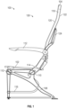
- a passenger seat assembly 100 may include a seat base 102 and one or more seat backs 104 supported relative to the seat base 102.
- the number of seat backs 104 should not be considered limiting on the disclosure.
- the number of seat backs 104 correspond with the number of passengers that the passenger seat is capable of carrying, and each seat back 104 and the corresponding portion of the seat base 102 define a particular passenger seat 126.
- the passenger seat assembly 100 is capable of carrying one passenger, and accordingly has one seat back 104 and one passenger seat 126.
- the passenger seat assembly 100 may be capable of carrying any desired number of passengers, such as one passenger, two passengers, three passengers, four passengers, or any other desired number of passengers.
- the passenger seat assembly 100 can likewise have any desired number of corresponding seat backs 104.
- the seat base 102 of the passenger seat assembly 100 generally includes a leg assembly 108 and at least one base frame tube 110.
- the seat base 102 may also include a support frame 106, an armrest 112, a spreader 114, a luggage bar 116, or other components. Cushioning (not illustrated) may be provided on any of the components of the seat base 102.
- the seat back 104 is connected to the seat base 102, and is often pivotable relative to the seat base 102 such that the seat back 104 can be positioned in various positions such as a taxi-takeoff-landing (TTL) position, a reclined position, etc.
- the seat back 104 is connected to the seat base 102 via the spreader 114.
- the seat back 104 includes a frame component 118 having a forward side 120 and an aft side 122.
- other components of the passenger seat assembly 100 such as a tray table 124, an in-flight entertainment monitor, or various other components may be supported on and/or relative to the seat back 104.
- tray table 124 may be pivotably connected to the spreader 114, and the tray table 124 may be movable relative to the aft side 122 of the seat back 104 between a stowed position and a deployed position.
- Cushioning (not illustrated) may be provided on any of the components of the seat back 104.
- Various structural assemblies of the seat base 102 and/or the seat back 104 may be subjected to different types of loads or forces when used.
- a lower portion of the spreader 114 e.g., the portion that engages the base frame tube(s) 110
- an upper portion of the spreader 114 e.g., the portion that connects with the seat back 104
- Other structural assemblies of the seat base 102 and/or the seat back 104 include, but are not limited to armrests and in-flight entertainment shrouds.
- one or more of the structural assemblies may include a structural shroud.
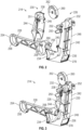
- FIGS. 2 and 3 illustrate an example of a spreader assembly 214 having an upper spreader 226 and a lower spreader 228. Similar to the spreader 114, the spreader assembly 214 is configured to connect a seat back with the seat base as well as support various other components such as a tray table. In various embodiments, and as discussed below, the upper spreader 226 is configured to engage with and/or support a seat back of the passenger seat and/or other components such as a tray table and may be subject to pushing loads during use, and the lower spreader 228 is configured to engage with the base frame tube(s) 110 and may be subject to pulling loads during use.
- the upper spreader 226 is a structural shroud 230 having a first end 232 and a second end 234 opposite from the first end 232.
- the structural shroud 230 also has an inner surface 246 and an outer surface 248 extending from the first end 232 to the second end 234.
- the inner surface 246 defines a central cavity 236 such that the structural shroud 230 is hollow along a length of the structural shroud 230.
- a cross-sectional shape of the structural shroud 230 may have a hollow center due to the central cavity 236.
- at least one of the first end 232 or the second end 234 defines an opening providing access to the central cavity 236. In the embodiment of FIGS.
- the first end 232 includes a first opening 238 providing access to the central cavity 236 and the second end 234 includes a second opening 240 providing access to the central cavity 236.
- a component of the passenger seat assembly including but not limited to a power outlet, USB outlet, or other amenity or component of the passenger seat may be provided in the intermediate opening 278.
- the first end 232 may be a top-most portion of the assembled upper spreader 226 and lower spreader 228.
- a stiffener or reinforcing component 251 may optionally be provided on the structural shroud 230.
- the stiffener or reinforcing component 251 may be provided on the inner surface 246 and/or the outer surface 248 as desired, and may stiffen the structural shroud 230. In various embodiments, the stiffener or reinforcing component 251 may be a separate component attached to the structural shroud or may be integrally formed with the structural shroud.
- the structural shroud 230 includes a first shroud 242 and a second shroud 244 connected to the first shroud 242.
- the first shroud 242 may be connected to the second shroud 244 via various suitable devices or mechanisms as desired such that the second shroud 244 may be selectively removed from the first shroud 242 (e.g., to allow greater access to the central cavity 236.
- the second shroud 244 may be removably connected to the first shroud 242 via mechanical fasteners such that cabling or wiring or other features within the central cavity 236 may be accessed as desired.
- the structural shroud 230 may be constructed from various suitable materials, including but not limited to aluminum, stainless steel, aramid fibers, polycarbonate, polypropylene, other metallic materials, composite materials, or other similar materials.
- the structural shroud 230 is constructed from a reinforced plastic such as a sheet molding compound.
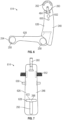
- the lower spreader 228 includes a forward end 254 and an aft end 256 opposite of the forward end 254.
- the lower spreader 228 does not include an inner surface extending along a length of the lower spreader and/or a central cavity.
- a cross-sectional shape of the lower spreader 228 may be different from that of the upper spreader 226.
- a center of the cross-sectional shape of the lower spreader 228 may be solid other than locations with apertures for the base frame tube(s) (discussed below).
- the forward end 254 may be a forward-most portion of the spreader assembly 214.
- the aft end 256 may be an aft-most portion and/or a lowermost portion of the spreader assembly 214, although it need not be the aft-most and/or the lowermost portion.
- a portion of the upper spreader 226 extends aft of the aft end 256.
- the lower spreader 228 may be a structural shroud similar to the structural shroud 230 and may define a central cavity such that the lower spreader 228 is hollow.
- the lower spreader 228 is a separate component that is connected to the upper spreader 226 via various suitable connectors or connecting mechanisms as desired, or in an unclaimed example, the lower spreader 228 and the upper spreader 226 may be formed as a monolithic or integral component.
- the lower spreader 228 includes one or more apertures 258 defined through a thickness of the lower spreader 228 between the forward end 254 and the aft end 256 that receive and engage base frame tube(s) of the passenger seat assembly.
- the lower spreader 228 includes two apertures 258.
- the lower spreader 228 may also include interfacing for other components of the seat base of the passenger seat assembly as desired.
- the lower spreader 228 may be constructed from various materials as desired suitable for engaging the base frame tube(s) and the upper spreader 226.
- the upper spreader 226 may be connected to the lower spreader 228 proximate to the second end 234.
- the lower spreader 228 may include an interface 266 that may be used to connect the upper spreader 226 with the lower spreader 228.
- the interface 266 includes a ridge 268 having a securing aperture 270.
- Various other types of interfaces 266 may be utilized as desired, and the ridge 268 and/or securing aperture 270 need not be included.
- the lower spreader 228 may be partially received within the central cavity 236, although it need not in other examples (see, e.g., FIG. 4 ).
- the upper spreader 226 may be connected to the lower spreader 228 via various suitable devices or mechanisms as desired, including but not limited to mechanical fasteners.
- Connectors and/or other components that engage with features of the seat back are provided on the structural shroud 230 and extend outwards from the outer surface 248. Such connectors and/or other components may be connected to the structural shroud 230 via various suitable mechanisms or devices as desired, or they may be integrally or monolithically formed with the structural shroud 230.
- the structural shroud 230 includes a table pivot 250 and a table stop 252 integrally formed with the structural shroud 230.
- the spreader assembly 214 includes an armrest pivot 260 supported proximate to the first end 232 of the upper spreader 226.
- the armrest pivot 260 may connected to the upper spreader 226 via various suitable devices or mechanisms as desired.
- the armrest pivot 260 includes one or more pivot grooves 262 that may interface with an armrest such that the armrest is pivotable relative to the spreader assembly 214.
- the spreader assembly 214 which may be referred to as a "split" spreader assembly, may be advantageous over traditional spreaders.
- the split spreader assembly 214 may maximize the inertia of the upper spreader 226 and reduce the mass needed to achieve the required stiffness to withstand forces from the armrest, seat back, etc.
- the split spreader assembly 214 may also optionally reduce the number of parts required for a spreader by embedding one or more of the components (e.g., stiffener, table stops, pivots, etc.), into the structural shroud. In some cases, the split spreader assembly 214 may reduce the amount of material waste that is caused by the typical crescent shape of traditional spreaders.
- the split spreader assembly 214 may also optimize stiffness and strength requirements for portion that engages the armrest, seat back, etc. independently from the stiffness and strength requirements for the portion that engages the base frame tube(s) and needing to withstand 16G loads.
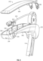
- FIGS. 4 and 5 illustrate an unclaimed example of a spreader assembly 414 that is substantially similar to the spreader assembly 214 and includes an upper spreader 426 and a lower spreader 428.
- the upper spreader 426 is similar to the upper spreader 226 and includes a structural shroud 430.
- the structural shroud 430 of the upper spreader 426 has a different shape than the structural shroud 230, and the structural shroud 430 is a monolithic and does not include the first shroud 242 and the second shroud 244.
- an interface component 464 may connect the armrest pivot 260 with the upper spreader 426.
- the lower spreader 428 is substantially similar to the lower spreader 428 except that the interface 266 includes a ridge 468 having two securing apertures 270.
- FIGS. 6 and 7 illustrate an unclaimed example of a spreader assembly 614 that is substantially similar to the spreader assembly 214 and includes an upper spreader 626 and a lower spreader 628.
- the upper spreader 626 is similar to the upper spreader 226 and includes a structural shroud 630.
- the structural shroud 630 of the upper spreader 626 has a different shape than the structural shroud 230, and the structural shroud 630 is a monolithic and does not include the first shroud 242 and the second shroud 244.
- the lower spreader 428 is substantially similar to the lower spreader 428 except that the interface 266 includes a ledge 672 that engages the upper spreader 626 and secures the lower spreader 628 to the upper spreader 626 without requiring separate fasteners or other joining devices.
- a table pivot 650 and a table stop 652 are separate components from the structural shroud 630 that are supported on the structural shroud 630.
- FIG. 8 illustrates an example of an armrest 812 having a structural shroud 830. Similar to the structural shroud 230, the structural shroud 830 includes a first shroud 842 and a second shroud 844. Compared to the structural shroud 230, the second end 234 of the structural shroud 830 does not include second opening 240. In the embodiment of FIG. 8 , the intermediate opening 278 is configured to receive an actuator 874 of the armrest 812, and cabling 876 for the actuator 874 may be housed within the central cavity 236.
Landscapes
- Engineering & Computer Science (AREA)
- Aviation & Aerospace Engineering (AREA)
- Transportation (AREA)
- Mechanical Engineering (AREA)
- Seats For Vehicles (AREA)
- Body Structure For Vehicles (AREA)
Claims (7)
- Passagiersitzanordnung (100) mit einer Spreizeranordnung (214), wobei die Spreizeranordnung (214) umfasst:einen unteren Spreizer (228), der sich in einer Vorwärtsrichtung erstreckt und einen vordersten Abschnitt der Spreizeranordnung (214) definiert; wobei der untere Spreizer (228) ein vorderes Ende (254) und ein hinteres, dem vorderen Ende (254) gegenüberliegendes Ende (256) umfasst, wobei der untere Spreizer (228) eine oder mehrere Öffnungen (258) umfasst, die durch eine Dicke des unteren Spreizers (228) hindurch zwischen dem vorderen Ende (254) und dem hinteren Ende (256) vorgesehen sind und dazu ausgelegt, ein oder mehrere Grundrahmenrohre aufzunehmen und die Passagiersitzanordnung (100) in Eingriff zu bringen, undeinen oberen Spreizer (226), der am unteren Spreizer (228) befestigt ist und sich in einer vertikalen Richtung relativ zum unteren Spreizer (228) erstreckt, wobei der obere Spreizer (226) eine strukturelle Abdeckung (230) mit einem ersten Ende (232) und einem zweiten, dem ersten Ende (232) gegenüberliegenden Ende (234), wobei der obere Spreizer (226) einen obersten Teil der Spreizeranordnung (214) definiert, wobei der obere Spreizer (226) dafür ausgelegt ist, eine Sitzlehne der Passagiersitzanordnung zu stützen, sodass auf der strukturellen Abdeckung Anschlüsse und/oder andere Komponenten für den Eingriff mit charakteristischen Elementen der Sitzlehne (230) vorgesehen sind und sich von einer Außenfläche (248) der strukturellen Abdeckung (230) nach außen erstrecken,dadurch gekennzeichnet, dass die strukturelle Abdeckung (230) eine erste Abdeckung (242) und eine zweite, an der ersten Abdeckung (242) befestigte Abdeckung (244) umfasst, und wobei die erste Abdeckung (242) und die zweite Abdeckung (244) gemeinsam einen zentralen Hohlraum definieren, so dass der obere Spreizer (226) hohl ist.
- Passagiersitzanordnung nach Anspruch 1, wobei sich eine Querschnittsform des oberen Spreizers (226) von einer Querschnittsform des unteren Spreizers (228) unterscheidet.
- Passagiersitzanordnung nach Anspruch 1 oder 2, außerdem mit der durch den oberen Spreizer (226) gestützten Sitzlehne und wobei der untere Spreizer (228) dafür ausgelegt ist, an mindestens einem Sitzrohr befestigt zu werden.
- Passagiersitzanordnung nach einem der Ansprüche 1 bis 3, wobei der obere Spreizer (226) an einem hinteren Abschnitt des unteren Spreizers (228) befestigt ist.
- Passagiersitzanordnung nach Anspruch 4, wobei der obere Spreizer ein hinterster Abschnitt der Spreizeranordnung (214) ist.
- Passagiersitzanordnung nach einem der Ansprüche 1 bis 5, außerdem mit einem Armlehnendrehzapfen, der an einem Ende des oberen, dem unteren Spreizer (228) gegenüberliegenden Spreizers (226) gestützt ist.
- Passagiersitzanordnung nach einem der Ansprüche 1 bis 6, außerdem mit einem Tischanschlag, der integral mit dem oberen Spreizer (226) ausgebildet ist.
Applications Claiming Priority (1)
| Application Number | Priority Date | Filing Date | Title |
|---|---|---|---|
| PCT/US2020/047006 WO2022039735A1 (en) | 2020-08-19 | 2020-08-19 | Structural shroud assembly for passenger seat |
Publications (2)
| Publication Number | Publication Date |
|---|---|
| EP4200212A1 EP4200212A1 (de) | 2023-06-28 |
| EP4200212B1 true EP4200212B1 (de) | 2025-01-29 |
Family
ID=72292687
Family Applications (2)
| Application Number | Title | Priority Date | Filing Date |
|---|---|---|---|
| EP20764891.6A Active EP4200212B1 (de) | 2020-08-19 | 2020-08-19 | Strukturelle verkleidungsanordnung für einen passagiersitz |
| EP21712931.1A Active EP4200213B1 (de) | 2020-08-19 | 2021-03-05 | Strukturelle anordnung für passagiersitz und zugehörige verfahren |
Family Applications After (1)
| Application Number | Title | Priority Date | Filing Date |
|---|---|---|---|
| EP21712931.1A Active EP4200213B1 (de) | 2020-08-19 | 2021-03-05 | Strukturelle anordnung für passagiersitz und zugehörige verfahren |
Country Status (4)
| Country | Link |
|---|---|
| US (2) | US12280698B2 (de) |
| EP (2) | EP4200212B1 (de) |
| CN (2) | CN115956050B (de) |
| WO (2) | WO2022039735A1 (de) |
Families Citing this family (5)
| Publication number | Priority date | Publication date | Assignee | Title |
|---|---|---|---|---|
| FR3088899B1 (fr) * | 2018-11-26 | 2022-03-18 | Zodiac Seats France | Procede d'assemblage entre une poutre et un element structurel d'un siege d'avion |
| DE102020106037A1 (de) * | 2020-03-05 | 2021-09-09 | Zim Flugsitz Gmbh | Fluggastsitz und Sitzreihe |
| WO2022039735A1 (en) * | 2020-08-19 | 2022-02-24 | Safran Seats Usa Llc | Structural shroud assembly for passenger seat |
| DE202022104164U1 (de) * | 2022-07-22 | 2022-07-28 | Bruns Holding Gmbh & Co. Kg | Rahmen für einen Fahrzeugsitz und Fahrzeugsitz mit einem selbigen |
| DE102023107192A1 (de) * | 2023-03-22 | 2024-09-26 | Recaro Aircraft Seating Gmbh & Co. Kg | Flugzeugsitzvorrichtung |
Citations (1)
| Publication number | Priority date | Publication date | Assignee | Title |
|---|---|---|---|---|
| WO1982003366A1 (en) * | 1981-03-30 | 1982-10-14 | Ian Cecil Toll | Improvements in aircraft seating |
Family Cites Families (39)
| Publication number | Priority date | Publication date | Assignee | Title |
|---|---|---|---|---|
| US4511178A (en) | 1982-12-16 | 1985-04-16 | Ptc Aerospace Inc. | Quick release mounting for seat back tray table |
| DE3903303A1 (de) * | 1989-02-04 | 1990-08-09 | Wilfried Wunderatzke | Sitz, insbesondere fahrzeugsitz |
| US5133587A (en) | 1989-11-20 | 1992-07-28 | Hadden Jr James R | Seat |
| US5575533A (en) * | 1994-02-25 | 1996-11-19 | Concept Analysis Corp. | Blow molded seat frame with integral reinforcement |
| US5746476A (en) * | 1995-06-02 | 1998-05-05 | Aluminum Company Of America | Load bearing automotive bench seat assembly |
| US6179381B1 (en) * | 1998-01-15 | 2001-01-30 | Krueger International, Inc. | Stationarily-mounted seating structure having electrical and data outlets |
| JP4348808B2 (ja) | 1999-12-27 | 2009-10-21 | トヨタ紡織株式会社 | 枠体に対する機能性部材の取付構造 |
| US6505890B2 (en) * | 2001-02-07 | 2003-01-14 | Am-Safe, Inc. | Aircraft seat structure |
| US6799805B2 (en) * | 2002-11-27 | 2004-10-05 | Be Aerospace, Inc. | Single beam aircraft passenger seat |
| DE102004026023A1 (de) * | 2004-05-27 | 2005-12-22 | Recaro Aircraft Seating Gmbh & Co. Kg | Sitz, insbesondere Fluggastsitz |
| US7716797B2 (en) * | 2006-12-22 | 2010-05-18 | The Boeing Company | Composite seat pan structure for a lightweight aircraft seat assembly |
| US8931847B2 (en) | 2010-10-18 | 2015-01-13 | Zodiac Seats France | Passenger seating assemblies and aspects thereof |
| WO2013109751A1 (en) * | 2012-01-17 | 2013-07-25 | Zodiac Seats Us Llc | Passenger seat |
| DE102012108119A1 (de) | 2012-08-31 | 2014-03-06 | Recaro Aircraft Seating Gmbh & Co. Kg | Sitzteilervorrichtung |
| CN203753407U (zh) * | 2014-04-01 | 2014-08-06 | 湖北航宇嘉泰飞机设备有限公司 | 带有机载娱乐设备的航空座椅椅盆 |
| DE102014212635A1 (de) * | 2014-06-30 | 2015-12-31 | Airbus Operations Gmbh | Fahrzeugsitz mit integrierter Halterung für elektronische Geräte |
| WO2016003982A1 (en) | 2014-07-02 | 2016-01-07 | Divergent Technologies, Inc. | Systems and methods for fabricating joint members |
| US11014676B2 (en) * | 2015-02-11 | 2021-05-25 | MIRUS Aircraft Seating Ltd. | Lightweight aircraft passenger seat assembly |
| US10850356B2 (en) | 2015-02-25 | 2020-12-01 | Hobart Brothers Llc | Aluminum metal-cored welding wire |
| US11370068B2 (en) | 2015-02-25 | 2022-06-28 | Hobart Brothers Llc | Systems and methods for additive manufacturing using aluminum metal-cored wire |
| US10227023B2 (en) * | 2015-03-31 | 2019-03-12 | Safran Seats Usa Llc | Energy absorbing brackets for passenger seats |
| EP3362358B1 (de) * | 2015-10-14 | 2021-04-28 | Safran Seats USA LLC | Passagiersitz einschliesslich eines rückennetz |
| US10493705B2 (en) | 2015-11-13 | 2019-12-03 | GM Global Technology Operations LLC | Additive manufacturing of a body component on a tube frame |
| US10557464B2 (en) | 2015-12-23 | 2020-02-11 | Emerson Climate Technologies, Inc. | Lattice-cored additive manufactured compressor components with fluid delivery features |
| EP3481721B1 (de) * | 2016-07-07 | 2024-04-10 | Safran Seats USA LLC | Sitzkomponenten aus verbundwerkstoff |
| WO2018191695A1 (en) | 2017-04-13 | 2018-10-18 | Arconic Inc. | Aluminum alloys having iron and rare earth elements |
| CN111386225B (zh) * | 2017-10-11 | 2024-02-13 | 赛峰座椅美国有限责任公司 | 两件式中心框架组件 |
| CN108583390A (zh) | 2018-01-04 | 2018-09-28 | 无锡全盛安仁机械有限公司 | 一种广泛采用铝合金铸件的汽车座椅骨架 |
| CZ309456B6 (cs) | 2018-08-02 | 2023-02-01 | DEA AIR s.r.o. | Příčný nosník pro použití v rámu leteckých sedadel a letecké sedadlo s alespoň dvěma těmito příčnými nosníky |
| WO2020050818A1 (en) * | 2018-09-04 | 2020-03-12 | Safran Seats Usa Llc | Light weight metal back with extra living space |
| US12115583B2 (en) | 2018-11-08 | 2024-10-15 | Divergent Technologies, Inc. | Systems and methods for adhesive-based part retention features in additively manufactured structures |
| US11279488B2 (en) * | 2020-02-20 | 2022-03-22 | B/E Aerospace, Inc. | Seat assembly with sacrificial backrest breakover feature |
| CN111349809B (zh) | 2020-03-27 | 2022-07-05 | 哈尔滨工业大学 | 一种含三维网络石墨烯的镁合金增材制造丝材的制备方法和应用 |
| WO2022039735A1 (en) * | 2020-08-19 | 2022-02-24 | Safran Seats Usa Llc | Structural shroud assembly for passenger seat |
| US11584274B1 (en) * | 2021-09-03 | 2023-02-21 | Safran Seats USA LL C | Modular leg assembly for passenger seat |
| US12054264B2 (en) * | 2022-02-07 | 2024-08-06 | B/E Aerospace, Inc. | Armrest assembly with hidden pivot shaft and discreet retention |
| US11999278B2 (en) | 2022-03-18 | 2024-06-04 | Seats Incorporated | Systems and methods for securing a fabric cover to an armrest |
| US20240058862A1 (en) | 2022-08-17 | 2024-02-22 | Honeywell International Inc. | Build materials having a powder mixture comprising graphene, methods of producing articles therefrom, and articles produced therewith |
| US20240140607A1 (en) * | 2022-10-26 | 2024-05-02 | Safran Seats Usa Llc | Integrated spreader assembly |
-
2020
- 2020-08-19 WO PCT/US2020/047006 patent/WO2022039735A1/en not_active Ceased
- 2020-08-19 CN CN202080103265.8A patent/CN115956050B/zh active Active
- 2020-08-19 US US18/021,354 patent/US12280698B2/en active Active
- 2020-08-19 EP EP20764891.6A patent/EP4200212B1/de active Active
-
2021
- 2021-03-05 US US18/021,383 patent/US12187174B2/en active Active
- 2021-03-05 WO PCT/US2021/021155 patent/WO2022039788A1/en not_active Ceased
- 2021-03-05 CN CN202180066050.8A patent/CN116234750A/zh active Pending
- 2021-03-05 EP EP21712931.1A patent/EP4200213B1/de active Active
Patent Citations (1)
| Publication number | Priority date | Publication date | Assignee | Title |
|---|---|---|---|---|
| WO1982003366A1 (en) * | 1981-03-30 | 1982-10-14 | Ian Cecil Toll | Improvements in aircraft seating |
Also Published As
| Publication number | Publication date |
|---|---|
| EP4200213B1 (de) | 2025-12-24 |
| WO2022039788A1 (en) | 2022-02-24 |
| US20230322138A1 (en) | 2023-10-12 |
| EP4200213A1 (de) | 2023-06-28 |
| US12280698B2 (en) | 2025-04-22 |
| EP4200212A1 (de) | 2023-06-28 |
| CN116234750A (zh) | 2023-06-06 |
| CN115956050A (zh) | 2023-04-11 |
| US20240034210A1 (en) | 2024-02-01 |
| US12187174B2 (en) | 2025-01-07 |
| WO2022039735A1 (en) | 2022-02-24 |
| CN115956050B (zh) | 2025-03-14 |
Similar Documents
| Publication | Publication Date | Title |
|---|---|---|
| EP4200212B1 (de) | Strukturelle verkleidungsanordnung für einen passagiersitz | |
| EP3181450B1 (de) | Eine armlehnenanordnung | |
| US10953987B2 (en) | Aircraft interior configuration with flexible use space | |
| EP2528473B1 (de) | Sitzlehnenanordnung | |
| US10730628B2 (en) | Aircraft seat back with non-tubular perimeter flange | |
| US6802568B1 (en) | Segmented beam aircraft passenger seat | |
| EP3939886B1 (de) | Konturierter klassenteiler | |
| EP3718894B1 (de) | Sitzlehne | |
| CN113165747B (zh) | 用于客运交通工具的商务舱座椅 | |
| CN112429242A (zh) | 可配置的机舱乘务人员座椅 | |
| EP3847053B1 (de) | Leichtgewichtige metallrückwand mit zusätzlichem wohnraum | |
| US20240198862A1 (en) | Multi-part leg assembly for a passenger seat | |
| EP3546339B1 (de) | Trennwand auslegung und entsprechende sitzanordnung | |
| EP4015385B1 (de) | Flugzeugpassagiersitzreihe mit flugbegleitersitz |
Legal Events
| Date | Code | Title | Description |
|---|---|---|---|
| STAA | Information on the status of an ep patent application or granted ep patent |
Free format text: STATUS: UNKNOWN |
|
| STAA | Information on the status of an ep patent application or granted ep patent |
Free format text: STATUS: THE INTERNATIONAL PUBLICATION HAS BEEN MADE |
|
| PUAI | Public reference made under article 153(3) epc to a published international application that has entered the european phase |
Free format text: ORIGINAL CODE: 0009012 |
|
| STAA | Information on the status of an ep patent application or granted ep patent |
Free format text: STATUS: REQUEST FOR EXAMINATION WAS MADE |
|
| 17P | Request for examination filed |
Effective date: 20230207 |
|
| AK | Designated contracting states |
Kind code of ref document: A1 Designated state(s): AL AT BE BG CH CY CZ DE DK EE ES FI FR GB GR HR HU IE IS IT LI LT LU LV MC MK MT NL NO PL PT RO RS SE SI SK SM TR |
|
| DAV | Request for validation of the european patent (deleted) | ||
| DAX | Request for extension of the european patent (deleted) | ||
| GRAP | Despatch of communication of intention to grant a patent |
Free format text: ORIGINAL CODE: EPIDOSNIGR1 |
|
| STAA | Information on the status of an ep patent application or granted ep patent |
Free format text: STATUS: GRANT OF PATENT IS INTENDED |
|
| INTG | Intention to grant announced |
Effective date: 20240830 |
|
| GRAS | Grant fee paid |
Free format text: ORIGINAL CODE: EPIDOSNIGR3 |
|
| GRAA | (expected) grant |
Free format text: ORIGINAL CODE: 0009210 |
|
| STAA | Information on the status of an ep patent application or granted ep patent |
Free format text: STATUS: THE PATENT HAS BEEN GRANTED |
|
| AK | Designated contracting states |
Kind code of ref document: B1 Designated state(s): AL AT BE BG CH CY CZ DE DK EE ES FI FR GB GR HR HU IE IS IT LI LT LU LV MC MK MT NL NO PL PT RO RS SE SI SK SM TR |
|
| REG | Reference to a national code |
Ref country code: GB Ref legal event code: FG4D |
|
| REG | Reference to a national code |
Ref country code: CH Ref legal event code: EP |
|
| REG | Reference to a national code |
Ref country code: DE Ref legal event code: R096 Ref document number: 602020045526 Country of ref document: DE |
|
| REG | Reference to a national code |
Ref country code: IE Ref legal event code: FG4D |
|
| REG | Reference to a national code |
Ref country code: NL Ref legal event code: MP Effective date: 20250129 |
|
| PG25 | Lapsed in a contracting state [announced via postgrant information from national office to epo] |
Ref country code: NL Free format text: LAPSE BECAUSE OF FAILURE TO SUBMIT A TRANSLATION OF THE DESCRIPTION OR TO PAY THE FEE WITHIN THE PRESCRIBED TIME-LIMIT Effective date: 20250129 |
|
| PG25 | Lapsed in a contracting state [announced via postgrant information from national office to epo] |
Ref country code: RS Free format text: LAPSE BECAUSE OF FAILURE TO SUBMIT A TRANSLATION OF THE DESCRIPTION OR TO PAY THE FEE WITHIN THE PRESCRIBED TIME-LIMIT Effective date: 20250429 |
|
| PG25 | Lapsed in a contracting state [announced via postgrant information from national office to epo] |
Ref country code: FI Free format text: LAPSE BECAUSE OF FAILURE TO SUBMIT A TRANSLATION OF THE DESCRIPTION OR TO PAY THE FEE WITHIN THE PRESCRIBED TIME-LIMIT Effective date: 20250129 |
|
| PG25 | Lapsed in a contracting state [announced via postgrant information from national office to epo] |
Ref country code: PL Free format text: LAPSE BECAUSE OF FAILURE TO SUBMIT A TRANSLATION OF THE DESCRIPTION OR TO PAY THE FEE WITHIN THE PRESCRIBED TIME-LIMIT Effective date: 20250129 |
|
| PG25 | Lapsed in a contracting state [announced via postgrant information from national office to epo] |
Ref country code: ES Free format text: LAPSE BECAUSE OF FAILURE TO SUBMIT A TRANSLATION OF THE DESCRIPTION OR TO PAY THE FEE WITHIN THE PRESCRIBED TIME-LIMIT Effective date: 20250129 |
|
| REG | Reference to a national code |
Ref country code: LT Ref legal event code: MG9D |
|
| PG25 | Lapsed in a contracting state [announced via postgrant information from national office to epo] |
Ref country code: IS Free format text: LAPSE BECAUSE OF FAILURE TO SUBMIT A TRANSLATION OF THE DESCRIPTION OR TO PAY THE FEE WITHIN THE PRESCRIBED TIME-LIMIT Effective date: 20250529 Ref country code: NO Free format text: LAPSE BECAUSE OF FAILURE TO SUBMIT A TRANSLATION OF THE DESCRIPTION OR TO PAY THE FEE WITHIN THE PRESCRIBED TIME-LIMIT Effective date: 20250429 |
|
| REG | Reference to a national code |
Ref country code: AT Ref legal event code: MK05 Ref document number: 1763235 Country of ref document: AT Kind code of ref document: T Effective date: 20250129 |
|
| PG25 | Lapsed in a contracting state [announced via postgrant information from national office to epo] |
Ref country code: HR Free format text: LAPSE BECAUSE OF FAILURE TO SUBMIT A TRANSLATION OF THE DESCRIPTION OR TO PAY THE FEE WITHIN THE PRESCRIBED TIME-LIMIT Effective date: 20250129 |
|
| PG25 | Lapsed in a contracting state [announced via postgrant information from national office to epo] |
Ref country code: LV Free format text: LAPSE BECAUSE OF FAILURE TO SUBMIT A TRANSLATION OF THE DESCRIPTION OR TO PAY THE FEE WITHIN THE PRESCRIBED TIME-LIMIT Effective date: 20250129 Ref country code: PT Free format text: LAPSE BECAUSE OF FAILURE TO SUBMIT A TRANSLATION OF THE DESCRIPTION OR TO PAY THE FEE WITHIN THE PRESCRIBED TIME-LIMIT Effective date: 20250529 |
|
| PG25 | Lapsed in a contracting state [announced via postgrant information from national office to epo] |
Ref country code: BG Free format text: LAPSE BECAUSE OF FAILURE TO SUBMIT A TRANSLATION OF THE DESCRIPTION OR TO PAY THE FEE WITHIN THE PRESCRIBED TIME-LIMIT Effective date: 20250129 Ref country code: GR Free format text: LAPSE BECAUSE OF FAILURE TO SUBMIT A TRANSLATION OF THE DESCRIPTION OR TO PAY THE FEE WITHIN THE PRESCRIBED TIME-LIMIT Effective date: 20250430 |
|
| PG25 | Lapsed in a contracting state [announced via postgrant information from national office to epo] |
Ref country code: AT Free format text: LAPSE BECAUSE OF FAILURE TO SUBMIT A TRANSLATION OF THE DESCRIPTION OR TO PAY THE FEE WITHIN THE PRESCRIBED TIME-LIMIT Effective date: 20250129 |
|
| PG25 | Lapsed in a contracting state [announced via postgrant information from national office to epo] |
Ref country code: SE Free format text: LAPSE BECAUSE OF FAILURE TO SUBMIT A TRANSLATION OF THE DESCRIPTION OR TO PAY THE FEE WITHIN THE PRESCRIBED TIME-LIMIT Effective date: 20250129 |
|
| PG25 | Lapsed in a contracting state [announced via postgrant information from national office to epo] |
Ref country code: SM Free format text: LAPSE BECAUSE OF FAILURE TO SUBMIT A TRANSLATION OF THE DESCRIPTION OR TO PAY THE FEE WITHIN THE PRESCRIBED TIME-LIMIT Effective date: 20250129 |
|
| PG25 | Lapsed in a contracting state [announced via postgrant information from national office to epo] |
Ref country code: DK Free format text: LAPSE BECAUSE OF FAILURE TO SUBMIT A TRANSLATION OF THE DESCRIPTION OR TO PAY THE FEE WITHIN THE PRESCRIBED TIME-LIMIT Effective date: 20250129 |
|
| PGFP | Annual fee paid to national office [announced via postgrant information from national office to epo] |
Ref country code: DE Payment date: 20250819 Year of fee payment: 6 |
|
| PG25 | Lapsed in a contracting state [announced via postgrant information from national office to epo] |
Ref country code: IT Free format text: LAPSE BECAUSE OF FAILURE TO SUBMIT A TRANSLATION OF THE DESCRIPTION OR TO PAY THE FEE WITHIN THE PRESCRIBED TIME-LIMIT Effective date: 20250129 |
|
| PGFP | Annual fee paid to national office [announced via postgrant information from national office to epo] |
Ref country code: GB Payment date: 20250825 Year of fee payment: 6 |
|
| PGFP | Annual fee paid to national office [announced via postgrant information from national office to epo] |
Ref country code: FR Payment date: 20250827 Year of fee payment: 6 |
|
| PG25 | Lapsed in a contracting state [announced via postgrant information from national office to epo] |
Ref country code: CZ Free format text: LAPSE BECAUSE OF FAILURE TO SUBMIT A TRANSLATION OF THE DESCRIPTION OR TO PAY THE FEE WITHIN THE PRESCRIBED TIME-LIMIT Effective date: 20250129 Ref country code: EE Free format text: LAPSE BECAUSE OF FAILURE TO SUBMIT A TRANSLATION OF THE DESCRIPTION OR TO PAY THE FEE WITHIN THE PRESCRIBED TIME-LIMIT Effective date: 20250129 |
|
| PG25 | Lapsed in a contracting state [announced via postgrant information from national office to epo] |
Ref country code: RO Free format text: LAPSE BECAUSE OF FAILURE TO SUBMIT A TRANSLATION OF THE DESCRIPTION OR TO PAY THE FEE WITHIN THE PRESCRIBED TIME-LIMIT Effective date: 20250129 |
|
| PG25 | Lapsed in a contracting state [announced via postgrant information from national office to epo] |
Ref country code: SK Free format text: LAPSE BECAUSE OF FAILURE TO SUBMIT A TRANSLATION OF THE DESCRIPTION OR TO PAY THE FEE WITHIN THE PRESCRIBED TIME-LIMIT Effective date: 20250129 |
|
| REG | Reference to a national code |
Ref country code: DE Ref legal event code: R097 Ref document number: 602020045526 Country of ref document: DE |
|
| PLBE | No opposition filed within time limit |
Free format text: ORIGINAL CODE: 0009261 |
|
| STAA | Information on the status of an ep patent application or granted ep patent |
Free format text: STATUS: NO OPPOSITION FILED WITHIN TIME LIMIT |
|
| 26N | No opposition filed |
Effective date: 20251030 |