EP4199271A1 - Haltevorrichtung für kontaktierungsvorrichtungen - Google Patents
Haltevorrichtung für kontaktierungsvorrichtungen Download PDFInfo
- Publication number
- EP4199271A1 EP4199271A1 EP22214585.6A EP22214585A EP4199271A1 EP 4199271 A1 EP4199271 A1 EP 4199271A1 EP 22214585 A EP22214585 A EP 22214585A EP 4199271 A1 EP4199271 A1 EP 4199271A1
- Authority
- EP
- European Patent Office
- Prior art keywords
- contacting
- blocking
- blocking element
- contacting device
- support profile
- Prior art date
- Legal status (The legal status is an assumption and is not a legal conclusion. Google has not performed a legal analysis and makes no representation as to the accuracy of the status listed.)
- Granted
Links
Images


Classifications
-
- H—ELECTRICITY
- H01—ELECTRIC ELEMENTS
- H01R—ELECTRICALLY-CONDUCTIVE CONNECTIONS; STRUCTURAL ASSOCIATIONS OF A PLURALITY OF MUTUALLY-INSULATED ELECTRICAL CONNECTING ELEMENTS; COUPLING DEVICES; CURRENT COLLECTORS
- H01R13/00—Details of coupling devices of the kinds covered by groups H01R12/70 or H01R24/00 - H01R33/00
- H01R13/62—Means for facilitating engagement or disengagement of coupling parts or for holding them in engagement
- H01R13/639—Additional means for holding or locking coupling parts together, after engagement, e.g. separate keylock, retainer strap
-
- H—ELECTRICITY
- H01—ELECTRIC ELEMENTS
- H01R—ELECTRICALLY-CONDUCTIVE CONNECTIONS; STRUCTURAL ASSOCIATIONS OF A PLURALITY OF MUTUALLY-INSULATED ELECTRICAL CONNECTING ELEMENTS; COUPLING DEVICES; CURRENT COLLECTORS
- H01R13/00—Details of coupling devices of the kinds covered by groups H01R12/70 or H01R24/00 - H01R33/00
- H01R13/62—Means for facilitating engagement or disengagement of coupling parts or for holding them in engagement
- H01R13/627—Snap or like fastening
- H01R13/6275—Latching arms not integral with the housing
-
- H—ELECTRICITY
- H01—ELECTRIC ELEMENTS
- H01R—ELECTRICALLY-CONDUCTIVE CONNECTIONS; STRUCTURAL ASSOCIATIONS OF A PLURALITY OF MUTUALLY-INSULATED ELECTRICAL CONNECTING ELEMENTS; COUPLING DEVICES; CURRENT COLLECTORS
- H01R25/00—Coupling parts adapted for simultaneous co-operation with two or more identical counterparts, e.g. for distributing energy to two or more circuits
- H01R25/14—Rails or bus-bars constructed so that the counterparts can be connected thereto at any point along their length
- H01R25/142—Their counterparts
Definitions
- the invention relates to a method for fastening a contacting device in a support profile and a contacting device for use in a support profile, the contacting device having a holding device with a number of retaining clips which engage behind an undercut of the support profile.
- Such systems generally relate to linear current distribution arrangements which are used in particular for lighting systems in buildings in order to lay lines for supplying devices with energy and/or signals in a cost-effective and visually appealing manner.
- Signals are understood to mean both the transmission of general signals, such as control signals, and the transmission of data, such as measurement or information data.
- the installation location of the devices can be chosen flexibly along a housing body of the power distribution arrangement and easily varied.
- the devices can thus be electrically conductively contacted with the conductors of a linear supply unit at a variably definable installation location using a contacting element.
- Such current distribution arrangements have the advantage that the devices are carried on the housing body both in an electrically contacting manner and also mechanically at the same time.
- the contacting devices within the meaning of these applications include both feeders, i.e. assemblies that feed corresponding signals and/or energy into the conductors to be contacted, but also taps that tap the corresponding signals and/or energy from the contacting conductors and feed them to external terminals.
- Linear power supply units which are mounted in a housing body, are usually used in the linear current distribution arrangements for distributing or forwarding the energy or signals.
- These supply units can, for example, be in the form of current-carrying profiles, but also in the form of ribbon cables.
- the current-carrying profiles are formed from a base body which extends in the longitudinal direction and has a number of chambers in which individual conductors are arranged.
- These current-carrying profiles are generally rigid and have a limited length due to the manufacturing process.
- For longer current distribution arrangements such as those used in larger factory buildings or warehouses, for example, several current-carrying profiles are usually required, which are then connected to one another both mechanically and electrically via a connecting element. Also at the When using ribbon cables, depending on the length of the ribbon cable, connecting elements can be used.
- Rigid round conductors are usually used as conductors, which are used or inserted into the chambers.
- a contacting device with a number of contact elements which acts as a tap, then engages in these chambers and contacts the contact elements with the corresponding conductors, as a result of which the signals or energy can be routed from the conductors to the terminal devices via the taps. Conversely, this also applies to corresponding feeders.
- the contacting device For reliable, permanent and sufficient contacting of the conductors by the contact elements, it is important that the contacting device is held firmly in the support profiles. It must be taken into account that the contacting devices are sometimes only installed directly on site, i.e. at the end customer's site, in the support profiles and may have to be relocated or replaced later.
- Fastening device for contacting devices in linear current distribution arrangements are in particular from the publications DE 10 2013 216 275 A1 , DE 10 2019 109 676 A1 , DE 20 2008 001 961 U1 , DE 20 2018 100 522 U1 known.
- the object of the invention is therefore to specify a particularly secure holder for contacting devices so that they can be easily assembled and, if necessary, disassembled again.
- the task is based on the consideration that common holding devices, which only engage in an undercut of a support profile, do not guarantee sufficient support, since the holding clamps can become detached from the undercuts on their own as a result of tensile forces on the connected conductors or the weight of the components themselves. which would lead to an interruption of the electrical contact.
- the holding elements are locked in position in such a way that they can no longer be independently pushed or pushed out of the undercuts.
- a blocking element is provided, which engages or grips behind the retaining clips, so that a movement of the retaining clips in the transverse direction, ie out of the undercuts, is prevented.
- the blocking element is also designed to be able to be moved between an open and a blocked position in the contacting direction, the movement of the retaining clips in the transverse direction in the area of the undercut being blocked only in the blocked position.
- the blocking element advantageously latches behind a projection of the support profile after it has been moved into the blocking position.
- the holding device in a preferred embodiment comprises two holding elements on two opposite sides of the contacting device, with a blocking element being arranged between the two holding elements on each side.
- the blocking element is designed in an advantageous embodiment with a number of blocking wings which protrude laterally from the blocking element and engage behind the retaining clips. When the blocking element is displaced, these blocking wings are thus guided along behind the retaining clips and, in the blocking position, lie behind the retaining clips in the region of the undercut.
- the blocking element For the dismantling it is necessary that the blocking element can be brought back into the open position. To do this, however, the latching of the blocking element must be released behind the second projection of the support profile. In order to make this particularly easy, the blocking element has a release device which releases this latching and then moves the blocking element into the open position.
- the blocking element achieves double securing of the contacting device in a support profile.
- the supporting profile in its blocked position ensures that the retaining clips do not fall out of the undercuts and, on the other hand, the blocking element itself is fixed in the supporting profile in the blocked position, so that an undesired displacement of the blocking element into the open position is avoided.
- the contacting device 1 comprises a contacting housing 2, in which a number of contact assemblies 4 are arranged.
- the contact assemblies 4 are arranged one behind the other in the transverse direction Q and can be mounted in the contact housing 2 both individually and in combination.
- the contact assemblies 4 include contact elements 6, which protrude from the contacting housing 2 of the contacting device 1 in the contacting direction K, and can be contacted with conductors 8, for example a linear power supply device.
- the contact assemblies 4 include connection devices provided on both sides for external conductors, which can be electrically connected to the conductors 8 of the linear power supply device via the contact assemblies 4 .
- the connection devices comprise insertion openings 10 formed in the longitudinal direction for receiving the external conductors.
- the contacting device 1 also includes a holding device 12, which in the exemplary embodiment shown here is arranged laterally, i.e. in front of and behind the contact assemblies 4 in the transverse direction Q, and enables the contacting device 1 to be fixed in a corresponding receptacle, for example in a support profile 14 .
- the holding device 12 according to the embodiment of figure 1 comprises two spaced-apart retaining clips 16 on each side.
- Each of the retaining clips 16 includes a base section 18, which grips under the contacting device 1 and thus supports the contacting device 1, a middle section 20, which runs along the lateral surface of the contacting housing 1 from the bottom to the top of the contacting housing 2 and together with the opposite retaining clip 16 on the other opposite lateral surface, the contacting device 1 is fixed in the transverse direction Q and a fixing section 22, which extends from the middle section and above the contacting housing essentially in the contacting direction K extends.
- This fixing section 22 is designed to engage and latch in an undercut 24 of the receiving device, in particular of a support profile 14 .
- it has a holding platform 26 which extends in the transverse direction Q and thus bends approximately perpendicularly from the extension of the middle section 20 .
- the fixing section 22 also has an insertion bevel 28, which protrudes from the holding platform 26 at an angle of less than 90°, preferably in the range of about 45°.
- This insertion bevel 28 allows the holding platform 26 to be guided past a corresponding projection 30 of the support profile 14 when the contacting device 1 is inserted and then to snap into the undercut 24 of the support profile 14 behind the projection 30 .
- the retaining clip 16 is individually in figure 3 enlarged again.
- the holding device 12 according to the embodiment according to the Figure 1 and Figure 2 also has a blocking element 32 on each side, which is arranged in the longitudinal direction L between the two retaining clips 16 in the embodiment shown there.
- the blocking element 32 is designed in such a way that it can be displaced in the contacting direction K between a first open position and a second blocking position. In the embodiment after Figure 1 and Figure 2 the blocking element 32 is shown in the open position.
- the blocking element 32 comprises a base body 34, which runs essentially in the contacting direction K, but is designed to taper slightly in the transverse direction Q in the contacting direction K.
- the thickness of the base body 34 in the transverse direction Q is thus thinner at the upper end, that is to say the end which in the installed state faces the conductors 12 to be contacted, than at the lower end. This leads to a supporting edge 36 being formed at the lower end of the base body.
- a release device 38 also extends in the transverse direction Q at the lower end of the base body 34 and is oriented in such a way that it runs under the contacting housing 2 .
- the base body 34 comprises two blocking wings 40, which protrude laterally on both sides in the longitudinal direction L from the base body 34. Depending on their position, these blocking wings 40 engage behind the fixing section 22 of the retaining clips 16.
- the blocking element 32 is shown individually in FIG figure 4 shown again.
- a curvature of the base body 34 can be clearly seen in the lower area, which provides the change in the thickness of the base body 34 described above.
- the base body 34 is hollow on the inside in this area, which means that the base body 34 acts like a leaf spring in the lower area, which is compressed when it is moved from the open to the closed position, as will be described in more detail below.
- the guide slot 42 of the blocking element 32 can be seen, which allows a guided displacement of the blocking element 32 within the limits set by the guide slot 42, ie from the open to the blocking position.
- FIG. 5 An exemplary inclusion of a contacting device in a support profile 14 is shown in figure 5 shown in front view.
- the support profile 14 comprises a linear current guide, which consists of a comb-like current guide profile 44, with a conductor 8 being inserted in each chamber.
- the contact assemblies 4 in the contacting device 1 are arranged next to one another at a distance from one another in such a way that each contact assembly 4 is assigned a conductor 8 and thus each contact assembly 4 can contact a conductor 8 .
- the contacting device 1 after figure 5 is not yet fixed in the support profile 14, but is just about to be pushed into the support profile 14.
- the holding platform 26 of the fixing section 22 of the holding clamps 16 has been guided past the projections 30 due to the insertion bevel 28 and is thereby deflected in the transverse direction Q to the center of the contacting device 1 .
- the blocking element is pushed from the open position into the blocking position, as is shown in figure 7 is shown. This is done by pushing the blocking element 32 upwards in the contacting direction K in the direction of the conductor 8 .
- the blocking effect is created in two ways. First, the blocking wings 40 in the fixing section 22 are pushed into the area of the holding platform 26, so that the holding platform 26 can no longer shift in the transverse direction Q, even under the action of force, since the blocking wings 40 block this path.
- the area of the lower base body 34 has the form and function of a leaf spring, which is compressed when the blocking element 32 is moved past the second projection 48 of the support profile 14 and then returns to its arched configuration in order to form a supporting edge 36 for the blocking element 32 .
- the flexibility required for snapping is ensured in part by the support profile 14 and the blocking element 32 itself.
- the contacting element 1 is thus now doubly fixed, namely at the top and bottom in the support profile 14 .
- a contacting element 1 with a blocking element 32 in the blocking position is in the exemplary embodiment according to FIG figure 8 shown again without the support profile 14.
- the blocking wings 40 which engage behind the retaining clips 16 in the area of the retaining platform 26 and prevent a transverse movement in the direction of the center of the contacting device 1, can be clearly seen.
- the contacting element 1 is shown with a blocking element 32 in the blocking position from below in order to clarify the release device 38 .
- the release device 38 includes a release eyelet 50 and, with an external tool that engages in the release eyelet 50 , enables the release device 38 to be pushed in the transverse direction Q towards the center of the contacting device 1 .
- the release device 38 is arranged centrally in the longitudinal direction L, so that it engages directly on the lower area of the base body 34, which is designed as a leaf spring, and can guide the leaf spring and thus the entire base body 34 past the second projection 48 of the support profile.
- the blocking element 32 is pulled out of the projection 48 of the support profile 14 in the region of the support edge 36 and freed, so that in the next step the blocking element 32 can be transferred from the blocked position to the open position. This also releases the holding platforms 26 again. This enables the contacting device 1 to be detached from the support profile 14.
Landscapes
- Connector Housings Or Holding Contact Members (AREA)
Abstract
Description
- Die Erfindung betrifft ein Verfahren zur Befestigung einer Kontaktierungsvorrichtung in einem Tragprofil und eine Kontaktierungsvorrichtung zum Einsatz in einem Tragprofil, wobei die Kontaktierungsvorrichtung eine Haltevorrichtung mit einer Anzahl von Halteklammern aufweist, die einen Hinterschnitt des Tragprofils hintergreifen.
- Derartige System betreffen in der Regel lineare Stromverteileranordnungen, die insbesondere für Beleuchtungssysteme in Gebäuden eingesetzt werden, um Leitungen zur Versorgung von Geräten mit Energie und/oder Signalen kostengünstig und optisch ansprechend zu verlegen. Unter Signalen wird dabei sowohl die Übertragung von allgemeinen Signalen, wie beispielsweise Steuersignalen, als auch die Übertragung von Daten, wie beispielsweise Mess- oder Informationsdaten, verstanden. Der Einbauort der Geräte kann flexibel entlang eines Gehäusekörpers der Stromverteileranordnung gewählt und leicht variiert werden. Die Geräte können damit auf einfache Weise mit einem Kontaktierungselement elektrisch leitend mit den Leitern einer linearen Versorgungseinheit an einem variabel festlegbaren Einbauort kontaktiert werden. Solche Stromverteileranordnungen haben den Vorteil, dass die Geräte sowohl elektrisch kontaktierend und auch zu gleich mechanisch an dem Gehäusekörper getragen werden.
- Die Kontaktierungsvorrichtungen im Sinne dieser Anmeldungen umfassen dabei sowohl Einspeiser, also Baugruppen, die entsprechende Signale und/oder Energie in die zu kontaktierenden Leiter einspeisen, aber ebenso Abgriffe, die die entsprechenden Signale und/oder Energie aus den kontaktierenden Leitern abgreifen und externen Endgeräten zuführen.
- Zur Verteilung bzw. Weiterleitung der Energie oder Signale werden in den linearen Stromverteileranordnungen meist lineare Versorgungseinheiten verwendet, die in einem Gehäusekörper gelagert werden. Diese Versorgungseinheiten können dabei beispielsweise als Stromführungsprofile aber auch als Flachbandkabel ausgebildet sein. Die Stromführungsprofile sind aus einem sich in Längsrichtung erstreckenden Grundkörper ausgebildet, der eine Anzahl von Kammern aufweist, in denen einzelne Leiter angeordnet sind. Diese Stromführungsprofile sind in der Regel starr ausgebildet und weisen herstellungsbedingt eine begrenzte Länge auf. Für längere Stromverteileranordnungen, wie sie beispielsweise in größeren Werks- oder Lagerhallen eingesetzt werden, sind daher üblicherweise mehrere Stromführungsprofile nötig, die dann über ein Verbindungselement sowohl mechanisch als auch elektrisch miteinander verbunden werden. Auch bei der Verwendung von Flachbandkabeln können je nach Länge des Flachbandkabels Verbindungselemente eingesetzt werden.
- Als Leiter werden üblicherweise starre Rundleiter verwendet, die in die Kammern eingesetzt oder eingelegt werden. Eine Kontaktierungsvorrichtung mit einer Anzahl von Kontaktelementen, die als Abgriff fungiert, greift dann in diese Kammern ein und kontaktiert die Kontaktelemente mit den entsprechenden Leitern, wodurch die Signale oder die Energie von den Leitern über die Abgriffe an die Endgeräte geleitet werden können. Umgekehrt ist dies auch für entsprechende Einspeiser gültig.
- Für eine zuverlässige, dauerhafte und ausreichende Kontaktierung der Leiter durch die Kontaktelemente ist eine feste Halterung der Kontaktierungsvorrichtung in den Tragprofilen wichtig. Dabei muss berücksichtigt werden, dass die Kontaktierungsvorrichtungen teilweise erst direkt vor Ort, also beim Endkunden in die Tragprofile eingesetzt werden und gegebenenfalls nachträglich umgesetzt oder ausgetauscht werden müssen.
- Befestigungsvorrichtung für Kontaktierungsvorrichtungen in linearen Stromverteileranordnungen sind insbesondere aus den Druckschriften
DE 10 2013 216 275 A1 ,DE 10 2019 109 676 A1 ,DE 20 2008 001 961 U1 ,DE 20 2018 100 522 U1 bekannt. - Die Aufgabe der Erfindung ist es daher eine besonders sichere Halterung für Kontaktierungsvorrichtungen anzugeben, damit diese einfach montiert und im Bedarfsfall auch wieder demontiert werden können.
- Die Aufgabe wird erfindungsgemäß durch die kennzeichnenden Merkmale der unabhängigen Ansprüche gelöst.
- Die Aufgabe geht von der Überlegung aus, dass gängige Haltevorrichtung, die lediglich in einen Hinterschnitt eines Tragprofils eingreifen keinen ausreichenden Halt gewährleisten, da durch Zugkräfte an den angeschlossenen Leitern oder durch das Eigengewicht der Komponenten, die Halteklammern sich gegebenenfalls eigenständig aus den Hinterschnitten lösen können, was zu einer Unterbrechung des elektrischen Kontaktes führen würde. Um dies zu verhindern, wird erfindungsgemäß vorgeschlagen, dass die Halteelemente in der Position derart gesperrt werden, dass sie nicht mehr eigenständig aus den Hinterschnitten herausgedrückt oder -geschoben werden können. Dazu ist ein Sperrelement vorgesehen, dass die Halteklammern hintergreift bzw. hinterfasst, damit eine Bewegung der Halteklammern in Querrichtung, also aus den Hinterschnitten heraus, unterbunden wird. Um eine einfache Montage und Demontage zu ermöglichen ist das Sperrelement darüber hinaus dazu ausgebildet zwischen einer Offen- und einer Sperrstellung in Kontaktierungsrichtung verschoben werden zu können, wobei nur in der Sperrstellung die Bewegung der Halteklammern in Querrichtung im Bereich des Hinterschnitts gesperrt ist.
- Um zusätzlich eine ungewollte bzw. eigenständige Bewegung des Sperrelements von der Sperrstellung in die Offenstellung zu verhindern, verrastet das Sperrelement nach der Verschiebung in die Sperrstellung in vorteilhafter Weise hinter einem Vorsprung des Tragprofils.
- Für eine symmetrische Anordnung und Verteilung der Haltekräfte umfasst die Haltevorrichtung in bevorzugter Ausgestaltung jeweils zwei Halteelemente an zwei gegenüberliegenden Seiten der Kontaktierungsvorrichtung, wobei auf jeder Seite jeweils ein Sperrelement zwischen beiden Halteelementen angeordnet ist. Um die Halteelemente besonders leicht zu hintergreifen und trotzdem eine Verschiebung zu ermöglichen, ist das Sperrelement in vorteilhafter Ausgestaltung mit einer Anzahl von Sperrflügeln ausgestaltet, die seitlich vom Sperrelement abstehen und die Halteklammern hintergreifen. Beim Verschieben des Sperrelements werden diese Sperrflügel somit hinter den Halteklammern entlanggeführt und liegen in der Sperrstellung im Bereich des Hinterschnittes hinter den Halteklammern.
- Für die Demontage ist es notwendig, dass das Sperrelement wieder in die Offenstellung gebracht werden kann. Dazu muss aber die Verrastung des Sperrelements hinter dem zweiten Vorsprung des Tragprofils gelöst werden. Um dies besonders leicht zu gestalten, weist das Sperrelement eine Lösevorrichtung auf, die diese Verrastung löst und das Sperrelement anschließend in die Offenstellung verschiebt.
- Die mit der Erfindung erzielten Vorteile bestehen insbesondere darin, dass durch das Sperrelement eine doppelte Sicherung der Kontaktierungsvorrichtung in einem Tragprofil erreicht wird. Einerseits sichert das Tragprofil in seiner Sperrstellung ein Herausfallen der Halteklammern aus den Hinterschnitten und andererseits wird das Sperrelement in der Sperrstellung selbst im Tragprofil fixiert, sodass ein unerwünschtes Verschieben des Sperrelements in die Offenstellung vermieden wird.
- Die Erfindung wird nachfolgend anhand einer Zeichnung näher erläutert. Dabei zeigen:
- Fig. 1
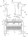
- eine Kontaktierungsvorrichtung im demontierten Zustand in isometrischer Ansicht,
- Fig. 2
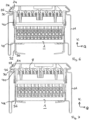
- eine Kontaktierungsvorrichtung im demontierten Zustand in Frontansicht,
- Fig. 3
- ein Halteelement,
- Fig. 4
- ein Sperrelement,
- Fig. 5
- eine Kontaktierungsvorrichtung in einem ersten Schritt beim Einsetzen in ein Tragprofil,
- Fig. 6
- eine Kontaktierungsvorrichtung in einem zweiten Schritt beim Einsetzen in ein Tragprofil,
- Fig. 7
- eine Kontaktierungsvorrichtung in einem dritten Schritt beim Einsetzen in ein Tragprofil,
- Fig. 8
- eine Kontaktierungsvorrichtung in der Sperrstellung in isometrischer Ansicht,
- Fig. 9
- eine fixierte Kontaktierungsvorrichtung in einem Tragprofil.
- Gleiche Merkmale sind in allen Figuren mit denselben Bezugszeichen versehen.
- Ein Ausführungsbeispiel einer Kontaktierungsvorrichtung 1 ist in
Figur 1 und in Frontansicht inFigur 2 dargestellt. Die Kontaktierungsvorrichtung 1 umfasst ein Kontaktierungsgehäuse 2, in das eine Anzahl von Kontaktbaugruppen 4 angeordnet sind. Die Kontaktbaugruppen 4 sind dabei in Querrichtung Q hintereinander angeordnet und können sowohl einzeln als auch im Verbund im Kontaktgehäuse 2 gelagert sein. Die Kontaktbaugruppen 4 umfassen Kontaktelemente 6, die in Kontaktierungsrichtung K aus dem Kontaktierungsgehäuse 2 der Kontaktierungsvorrichtung 1 hervorstehen, und mit Leitern 8, beispielsweise einer linearen Stromversorgungseinrichtung kontaktiert werden können. Weiterhin umfassen die Kontaktbaugruppen 4 über beidseitig vorgesehene Anschlussvorrichtungen für externe Leiter, die mit den Leitern 8 der linearen Stromversorgungseinrichtung elektrisch über die Kontaktbaugruppen 4 verbunden werden können. Dazu umfassen die Anschlussvorrichtungen in Längsrichtung ausgebildete Einführöffnungen 10, zur Aufnahme der externen Leiter. - Die Kontaktierungsvorrichtung 1 umfasst neben dem Kontaktierungsgehäuse 2 auch eine Haltevorrichtung 12, die im hier dargestellten Ausführungsbeispiel seitlich, in Querrichtung Q also vor und hinter den Kontaktbaugruppen 4 angeordnet sind und eine Fixierung der Kontaktierungsvorrichtung 1 in einer entsprechenden Aufnahme, beispielsweise in einem Tragprofil 14, ermöglicht. Die Haltevorrichtung 12 nach dem Ausführungsbeispiel der
Figur 1 umfasst dabei auf jeder Seite zwei beabstandet zueinander angeordnete Halteklammern 16. Jede der Halteklammern 16 umfasst dabei einen Bodenabschnitt 18, der unter die Kontaktierungsvorrichtung 1 greift und somit die Kontaktierungsvorrichtung 1 trägt, einen Mittelabschnitt 20, der entlang der seitlichen Fläche des Kontaktierungsgehäuses 1 von der Unterseite bis zur Oberseite des Kontaktierungsgehäuses 2 verläuft und zusammen mit der gegenüberliegenden Halteklammer 16 auf der anderen gegenüberliegenden seitlichen Fläche die Kontaktierungsvorrichtung 1 in Querrichtung Q fixiert und einen Fixierungsabschnitt 22, der sich von dem Mittelabschnitt aus erstreckt und sich oberhalb des Kontaktierungsgehäuses im Wesentlichen in Kontaktierungsrichtung K erstreckt. - Dieser Fixierungsabschnitt 22 ist dazu ausgebildet in einen Hinterschnitt 24 der Aufnahmevorrichtung, insbesondere eines Tragprofils 14, einzugreifen und darin zu verrasten. Dazu weist er eine Halteplattform 26 auf, die sich in Querrichtung Q erstreckt und somit in etwa senkrecht von der Verlängerung des Mittelabschnittes 20 abknickt. Zur besseren und leichteren Montage der Kontaktierungsvorrichtung 1 weist der Fixierungsabschnitt 22 darüber hinaus eine Einführschräge 28 auf, die im Winkel von unter 90°, bevorzugt im Bereich von etwa 45°, von der Halteplattform 26 absteht. Durch diese Einführschräge 28 kann die Halteplattform 26 beim Einsetzen der Kontaktierungsvorrichtung 1 an einem entsprechenden Vorsprung 30 des Tragprofils 14 vorbeigeführt werden und anschließend hinter dem Vorsprung 30 in den Hinterschnitt 24 des Tragprofils 14 einrasten. Die Halteklammer 16 ist einzeln in
Figur 3 nochmal vergrößert dargestellt. - Die Haltevorrichtung 12 nach dem Ausführungsbeispiel nach der
Figur 1 und Figur 2 weist darüber hinaus ebenfalls auf jeder Seite ein Sperrelement 32 auf, welches in der dort dargestellten Ausführung in Längsrichtung L zwischen den beiden Halteklammern 16 angeordnet ist. Das Sperrelement 32 ist so ausgebildet, dass es in Kontaktierungsrichtung K zwischen einer ersten Offenstellung und einer zweiten Sperrstellung verschoben werden kann. Im Ausführungsbeispiel nachFigur 1 und Figur 2 ist das Sperrelement 32 in Offenstellung gezeigt. Das Sperrelement 32 umfasst einen Grundkörper 34, der in im Wesentlichen in Kontaktierungsrichtung K verläuft, in Querrichtung Q aber in Kontaktierungsrichtung K leicht verjüngend ausgebildet ist. Die Dicke des Grundkörpers 34 in Querrichtung Q ist somit am oberen Ende, das heißt dem Ende, welches im eingebauten Zustand den zu kontaktierenden Leitern 12 zugewandt ist, dünner ausgebildet als am unteren Ende. Dies führt dazu, dass am unteren Ende des Grundkörpers eine Abstützkante 36 ausgebildet ist. Ebenfalls am unteren Ende des Grundkörpers 34 erstreckt sich in Querrichtung Q eine Lösevorrichtung 38, die so orientiert ist, dass sie unter das Kontaktierungsgehäuse 2 verläuft. Im oberen Bereich des Grundkörpers 34 umfasst der Grundkörper 34 zwei Sperrflügel 40, die seitlich zu beiden Seiten in Längsrichtung L von dem Grundkörper 34 abstehen. Diese Sperrflügel 40 hintergreifen je nach Stellung den Fixierungsabschnitt 22 der Halteklammern 16. - Das Sperrelement 32 ist in einer Einzeldarstellung in
Figur 4 nochmal dargestellt. Dabei ist deutlich eine Wölbung des Grundkörpers 34 im unteren Bereich zu erkennen, die die oben beschriebene Änderung der Dicke des Grundkörpers 34 liefert. Der Grundkörper 34 ist in diesem Bereich innen hohl ausgebildet, was dazu führt, dass der Grundkörper 34 im unteren Bereich wie eine Blattfeder wirkt, die beim Verschieben von der Offen- in die Sperrstellung zusammengedrückt wird, wie dies weiter unten näher beschrieben wird. Ebenfalls inFigur 4 ersichtlich ist der Führungsschlitz 42 des Sperrelements 32 der eine geführte Verschiebung des Sperrelements 32 innerhalb der durch den Führungsschlitz 42 gesetzten Grenzen, also von der Offen- in die Sperrstellung, ermöglicht. - Eine beispielhafte Aufnahme einer Kontaktierungsvorrichtung in einem Tragprofil 14 ist in
Figur 5 in Frontansicht dargestellt. Das Tragprofil 14 umfasst dabei eine lineare Stromführung, die aus einem kammartigen Stromführungsprofil 44 besteht, wobei in jeder Kammer ein Leiter 8 eingelegt ist. Die Kontaktbaugruppen 4 in der Kontaktierungsvorrichtung 1 sind dabei derart beabstandet nebeneinander angeordnet, dass jeder Kontaktbaugruppe 4 ein Leiter 8 zugeordnet ist und somit jede Kontaktbaugruppe 4 einen Leiter 8 kontaktieren kann. Die Kontaktierungsvorrichtung 1 nachFigur 5 ist dabei noch nicht im Tragprofil 14 fixiert, sondern befindet sich gerade dabei in das Tragprofil 14 eingeschoben zu werden. Die Halteplattform 26 des Fixierungsabschnittes 22 der Halteklammern 16 ist aufgrund der Einführschräge 28 an den Vorsprüngen 30 vorbei geführt worden und dadurch in Querrichtung Q zur Mitte der Kontaktierungsvorrichtung 1 ausgelenkt. - In der Darstellung der
Figur 6 , ist der Fixierungsabschnitt 22 nun vollständig an dem Vorsprung 30 vorbei geführt worden und die Halteplattform 26 schnappt in den Hinterschnitt 24 des Tragprofils 14 ein. Bereits hier wird die Kontaktierungsvorrichtung 1 vollständig von der Haltevorrichtung 12 gehalten, da die Halteplattform 26 auf dem Vorsprung 30 aufliegt. Das Sperrelement 32 befindet sich weiter in der Offenstellung. - Um ein unabsichtliches Lösen der Kontaktierungsvorrichtung 1 zu verhindern, insbesondere zu verhindern, dass die Halteplattform 26 durch Krafteinwirkung aus dem Hinterschnitt 24 des Tragprofils 14 herausgezogen wird, wird das Sperrelement von der Offenstellung in die Sperrstellung geschoben, wie dies in
Figur 7 dargestellt ist. Dies geschieht, indem das Sperrelement 32 in Kontaktierungsrichtung K in Richtung der Leiter 8 nach oben geschoben wird. Die Sperrwirkung entsteht dabei auf doppelte Weise. Zunächst werden die Sperrflügel 40 im Fixierungsabschnitt 22 in den Bereich der Halteplattform 26 geschoben, sodass sich die Halteplattform 26 auch unter Krafteinwirkung nicht mehr in Querrichtung Q verschieben kann, da die Sperrflügel 40 diesen Weg blockieren. Weiterhin schnappt das leicht gewölbt ausgeführte Sperrelement 32 hinter einen zweiten Vorsprung 48 des Tragprofils 14, sodass die Abstützkante 36 des Sperrelements 32 hinter diesem Vorsprung 48 liegt und sich auf diesem abstützt. Dabei hat der Bereich des unteren Grundkörpers 34 die Form und Funktion einer Blattfeder, die beim Vorbeiführen des Sperrelements 32 an dem zweiten Vorsprung 48 des Tragprofils 14 gestaucht wird und anschließend wieder in die gewölbte Ausbildung zurückkehrt, um eine Abstützkante 36 für das Sperrelement 32 zu bilden. Die für das Schnappen notwendige Flexibilität wird anteilig durch das Tragprofil 14 und das Sperrelement 32 selbst gewährleistet. Das Kontaktierungselement 1 ist somit nunmehr doppelt, nämlich oben und unten im Tragprofil 14 fixiert. - Ein Kontaktierungselement 1 mit einem Sperrelement 32 in Sperrstellung ist im Ausführungsbeispiel nach der
Figur 8 noch einmal ohne das Tragprofil 14 gezeigt. Deutlich zu erkennen sind die Sperrflügel 40, die im Bereich der Halteplattform 26 die Halteklammern 16 hintergreifen und eine Querbewegung in Richtung der Mitte der Kontaktierungsvorrichtung 1 verhindern. - Im Ausführungsbeispiel nach der
Figur 9 , ist das Kontaktierungselement 1 mit einem Sperrelement 32 in Sperrstellung von unten gezeigt, um die Lösevorrichtung 38 zu verdeutlichen. Die Lösevorrichtung 38 umfasst dabei eine Löseöse 50 und ermöglicht mit einem externen Werkzeug, welches in die Löseöse 50 eingreift, dass die Lösevorrichtung 38 in Querrichtung Q in Richtung der Mitte der Kontaktierungsvorrichtung 1 geschoben werden kann. Die Lösevorrichtung 38 ist dabei in Längsrichtung L mittig angeordnet, sodass sie direkt auf den unteren Bereich des Grundkörpers 34, der als Blattfeder ausgebildet ist eingreift und die Blattfeder und damit den gesamten Grundkörper 34 an dem zweiten Vorsprung 48 des Tragprofils vorbeiführen kann. Dadurch wird das Sperrelement 32 im Bereich der Abstützkante 36 aus dem Vorsprung 48 des Tragprofils 14 hervorgezogen und befreit, sodass im nächsten Schritt das Sperrelement 32 aus der Sperrstellung in die Offenstellung überführt werden kann. Dadurch werden auch die Halteplattformen 26 wieder freigegeben. Dies ermöglicht ein Lösen der Kontaktierungsvorrichtung 1 aus dem Tragprofil 14. -
- 1
- Kontaktierungsvorrichtung
- 2
- Kontaktierungsgehäuse
- 4
- Kontaktbaugruppen
- 6
- Kontaktelement
- 8
- Leiter
- 10
- Einführöffnung
- 12
- Haltevorrichtung
- 14
- Tragprofil
- 16
- Halteklammer
- 18
- Bodenabschnitt
- 20
- Mittelabschnitt
- 22
- Fixierungsabschnitt
- 24
- Hinterschnitt
- 26
- Halteplattform
- 28
- Einführschräge
- 30
- erster Vorsprung
- 32
- Sperrelement
- 34
- Grundkörper
- 36
- Abstützkante
- 38
- Lösevorrichtung
- 40
- Sperrflügel
- 42
- Führungsschlitz
- 44
- Stromführungsprofil
- 48
- zweiter Vorsprung
- 50
- Löseöse
- Q
- Querrichtung
- L
- Längsrichtung
- K
- Kontaktierungsrichtung
Claims (6)
- Verfahren zur Befestigung einer Kontaktierungsvorrichtung (1) in einem Tragprofil (14), wobei die Kontaktierungsvorrichtung (1) eine Haltevorrichtung (12) umfasst, die eine Anzahl von Halteklammern (16) aufweist, wobei die Halteklammern (16) beim Einsetzen der Kontaktierungsvorrichtung (1) an vorgesehenen Hinterschnitten (24) des Tragprofils (14) vorbeigeführt werden und diese anschließend hintergreifen, dadurch gekennzeichnet, dass die Haltevorrichtung (12) zumindest ein Sperrelement (32) aufweist, welches zwischen einer Offen- und einer Sperrstellung verschoben werden kann, und wobei das Sperrelement (32) beim Einsetzen der Kontaktierungsvorrichtung (1) in der Offenstellung liegt und nach dem Einsetzen in die Sperrstellung geschoben wird, um ein lösen der Halteklammern (16) aus dem Hinterschnitt (24) zu verhindern.
- Verfahren nach Anspruch 1, dadurch gekennzeichnet, dass das Sperrelement (32) beim Verschieben in die Sperrstellung hinter einem Vorsprung des Tragprofils (14) verrastet, sodass es in der Sperrstellung fixiert ist.
- Kontaktierungsvorrichtung (1) zum Einsatz in einem Tragprofil (14), wobei die Kontaktierungsvorrichtung (1) eine Haltevorrichtung (12) mit einer Anzahl von Halteklammern (16) aufweist, die einen Hinterschnitt (24) des Tragprofils (14) hintergreifen, dadurch gekennzeichnet, dass die Haltevorrichtung (12) ein Sperrelement (32) umfasst, welches zwischen einer Offen- und einer Sperrstellung verschiebbar angeordnet ist und wobei das Sperrelement (32) in der Sperrstellung die Halteklammern (16) im Bereich des Hinterschnitts (24) hinterfasst.
- Kontaktierungsvorrichtung (1) nach Anspruch 3, dadurch gekennzeichnet, dass die Haltevorrichtung (12) an zwei gegenüberliegenden Seiten der Kontaktierungsvorrichtung (1) angeordnet ist und pro Seite jeweils zwei Halteklammern (16) mit einem zwischen diesem angeordneten Sperrelement (32) aufweist.
- Kontaktierungsvorrichtung (1) nach Anspruch 3 oder 4, dadurch kennzeichnet, dass das Sperrelement (32) eine Anzahl von Sperrflügeln (40) umfasst, die seitlich vom Sperrelement (32) abstehen und die Halteklammern (32) in der Sperrstellung hinterfassen.
- Kontaktierungsvorrichtung (1) nach einem der Ansprüche 3 bis 5, dadurch gekennzeichnet, dass die Sperrelement (32) eine Lösevorrichtung (38) aufweist, durch die das Sperrelement (32) in Zusammenwirkung mit einem externen Werkzeug aus der Sperrstellung in die Offenstellung verschoben werden kann.
Applications Claiming Priority (1)
| Application Number | Priority Date | Filing Date | Title |
|---|---|---|---|
| DE102021133754.2A DE102021133754A1 (de) | 2021-12-17 | 2021-12-17 | Haltevorrichtung für Kontaktierungsvorrichtungen |
Publications (3)
| Publication Number | Publication Date |
|---|---|
| EP4199271A1 true EP4199271A1 (de) | 2023-06-21 |
| EP4199271C0 EP4199271C0 (de) | 2025-10-29 |
| EP4199271B1 EP4199271B1 (de) | 2025-10-29 |
Family
ID=84537999
Family Applications (1)
| Application Number | Title | Priority Date | Filing Date |
|---|---|---|---|
| EP22214585.6A Active EP4199271B1 (de) | 2021-12-17 | 2022-12-19 | Haltevorrichtung für kontaktierungsvorrichtungen |
Country Status (3)
| Country | Link |
|---|---|
| EP (1) | EP4199271B1 (de) |
| DE (1) | DE102021133754A1 (de) |
| PL (1) | PL4199271T3 (de) |
Citations (6)
| Publication number | Priority date | Publication date | Assignee | Title |
|---|---|---|---|---|
| DE202008001961U1 (de) | 2008-02-13 | 2008-04-17 | Ridi Leuchten Gmbh | Kontaktierungssystem für Lichtbänder oder Leuchten |
| EP2105658A1 (de) * | 2008-03-28 | 2009-09-30 | Etap N.V. | Leuchtmodul und Rahmen |
| DE102013216275A1 (de) | 2013-07-15 | 2015-03-19 | Ridi Leuchten Gmbh | Leuchte |
| DE202018100522U1 (de) | 2018-01-31 | 2019-05-03 | Zumtobel Lighting Gmbh | Lichtbandsystem |
| DE102019109676A1 (de) | 2018-08-09 | 2020-02-13 | Trilux Gmbh & Co. Kg | Haltefeder für Leuchte |
| EP3653925A1 (de) * | 2018-11-15 | 2020-05-20 | TRILUX GmbH & Co. KG | Abgedichtete leuchte |
-
2021
- 2021-12-17 DE DE102021133754.2A patent/DE102021133754A1/de active Pending
-
2022
- 2022-12-19 EP EP22214585.6A patent/EP4199271B1/de active Active
- 2022-12-19 PL PL22214585.6T patent/PL4199271T3/pl unknown
Patent Citations (6)
| Publication number | Priority date | Publication date | Assignee | Title |
|---|---|---|---|---|
| DE202008001961U1 (de) | 2008-02-13 | 2008-04-17 | Ridi Leuchten Gmbh | Kontaktierungssystem für Lichtbänder oder Leuchten |
| EP2105658A1 (de) * | 2008-03-28 | 2009-09-30 | Etap N.V. | Leuchtmodul und Rahmen |
| DE102013216275A1 (de) | 2013-07-15 | 2015-03-19 | Ridi Leuchten Gmbh | Leuchte |
| DE202018100522U1 (de) | 2018-01-31 | 2019-05-03 | Zumtobel Lighting Gmbh | Lichtbandsystem |
| DE102019109676A1 (de) | 2018-08-09 | 2020-02-13 | Trilux Gmbh & Co. Kg | Haltefeder für Leuchte |
| EP3653925A1 (de) * | 2018-11-15 | 2020-05-20 | TRILUX GmbH & Co. KG | Abgedichtete leuchte |
Also Published As
| Publication number | Publication date |
|---|---|
| DE102021133754A1 (de) | 2023-06-22 |
| PL4199271T3 (pl) | 2026-03-23 |
| EP4199271C0 (de) | 2025-10-29 |
| EP4199271B1 (de) | 2025-10-29 |
Similar Documents
| Publication | Publication Date | Title |
|---|---|---|
| EP3369138B1 (de) | Kontaktierungsvorrichtung zum kontaktieren eines elektrischen leiters an eine elektrische leiterbahn | |
| EP3507866B1 (de) | Leiteranschlussklemme | |
| DE102019127232B3 (de) | Anschlusseinrichtung zum Anschließen einer elektrischen Leitung | |
| EP3276757B1 (de) | Stromschienenverbinder und set aus zwei komplementären stromschienenverbindern und metalltrögen mit jeweils darin aufgenommenem stromführungsprofil | |
| DE102017125275B4 (de) | Stromführungsprofil-Verbinder und Stromführungsanordnung | |
| DE102012011676B4 (de) | Befestigungsklemme und Baueinheit mit zwei Befestigungsklemmen und mehreren nebeneinander angeordneten Reihenklemmen | |
| DE102013110477B4 (de) | Durchführungsklemme und elektrische Baueinrichtung | |
| DE102010055789B4 (de) | Stromschienenverbinder und Stromschienensystem mit mindestens zwei benachbarten Stromschienen und einem Stromschienenverbinder | |
| EP2018684B1 (de) | Modul mit anschlüssen für aktoren und/oder sensoren | |
| EP3954007B1 (de) | Stromsammelschienensystem mit mindestens einer in einem berührungsschutzgehäuse gehaltenen stromsammelschiene | |
| EP3701606A1 (de) | Leitungshaltersystem, verbindungsteil, stromschienenelement, stromschienensystem, mechanisches verbindungselement, verfahren zur herstellung eines stromschienenelements und verfahren zur herstellung eines stromschienensystems | |
| DE102010040322A1 (de) | Schiebevorrichtung zur Befestigung eines Gehäuses | |
| EP3050166A1 (de) | Durchführungsklemme | |
| EP3856568B1 (de) | Dehnverbinder für eine schleifleitung und schleifleitung | |
| EP3772607B1 (de) | Leuchte mit gedämpftem abgriff | |
| EP4199271B1 (de) | Haltevorrichtung für kontaktierungsvorrichtungen | |
| DE102021126225B4 (de) | Federkäfig für ein verbindungselement und verbindungselement | |
| DE102008019763B4 (de) | Baueinheit mit einer Befestigungsvorrichtung zur lösbaren rastenden Halterung eines elektrischen Verteilers | |
| EP3183779B1 (de) | Kontaktelement und steckverbinder | |
| EP4449563A1 (de) | Modulare leuchte mit kontakteinrichtung | |
| DE102005050778B4 (de) | Kontaktgehäuse sowie elektrische Kontaktvorrichtung | |
| EP1505701A1 (de) | Auf Stromschienen anzuordnendes elektrischesTeil | |
| DE3122611C2 (de) | Verschlußkappe für elektrische Kontaktsysteme | |
| EP1616371B1 (de) | Anschlussleiste für eine klemmenanordnung für einen kleinverteiler und/oder ein verteilerfeld einer elektrischen niederspannungsschaltanlage | |
| DE102021111100B4 (de) | Anschlussvorrichtung und Verfahren zum Montieren einer solchen Anschlussvorrichtung |
Legal Events
| Date | Code | Title | Description |
|---|---|---|---|
| STAA | Information on the status of an ep patent application or granted ep patent |
Free format text: STATUS: UNKNOWN |
|
| PUAI | Public reference made under article 153(3) epc to a published international application that has entered the european phase |
Free format text: ORIGINAL CODE: 0009012 |
|
| STAA | Information on the status of an ep patent application or granted ep patent |
Free format text: STATUS: THE APPLICATION HAS BEEN PUBLISHED |
|
| AK | Designated contracting states |
Kind code of ref document: A1 Designated state(s): AL AT BE BG CH CY CZ DE DK EE ES FI FR GB GR HR HU IE IS IT LI LT LU LV MC ME MK MT NL NO PL PT RO RS SE SI SK SM TR |
|
| STAA | Information on the status of an ep patent application or granted ep patent |
Free format text: STATUS: REQUEST FOR EXAMINATION WAS MADE |
|
| 17P | Request for examination filed |
Effective date: 20231220 |
|
| RBV | Designated contracting states (corrected) |
Designated state(s): AL AT BE BG CH CY CZ DE DK EE ES FI FR GB GR HR HU IE IS IT LI LT LU LV MC ME MK MT NL NO PL PT RO RS SE SI SK SM TR |
|
| GRAP | Despatch of communication of intention to grant a patent |
Free format text: ORIGINAL CODE: EPIDOSNIGR1 |
|
| STAA | Information on the status of an ep patent application or granted ep patent |
Free format text: STATUS: GRANT OF PATENT IS INTENDED |
|
| INTG | Intention to grant announced |
Effective date: 20250522 |
|
| GRAS | Grant fee paid |
Free format text: ORIGINAL CODE: EPIDOSNIGR3 |
|
| GRAA | (expected) grant |
Free format text: ORIGINAL CODE: 0009210 |
|
| STAA | Information on the status of an ep patent application or granted ep patent |
Free format text: STATUS: THE PATENT HAS BEEN GRANTED |
|
| AK | Designated contracting states |
Kind code of ref document: B1 Designated state(s): AL AT BE BG CH CY CZ DE DK EE ES FI FR GB GR HR HU IE IS IT LI LT LU LV MC ME MK MT NL NO PL PT RO RS SE SI SK SM TR |
|
| REG | Reference to a national code |
Ref country code: CH Ref legal event code: F10 Free format text: ST27 STATUS EVENT CODE: U-0-0-F10-F00 (AS PROVIDED BY THE NATIONAL OFFICE) Effective date: 20251029 Ref country code: GB Ref legal event code: FG4D Free format text: NOT ENGLISH |
|
| REG | Reference to a national code |
Ref country code: DE Ref legal event code: R096 Ref document number: 502022005928 Country of ref document: DE |
|
| REG | Reference to a national code |
Ref country code: IE Ref legal event code: FG4D Free format text: LANGUAGE OF EP DOCUMENT: GERMAN |
|
| U01 | Request for unitary effect filed |
Effective date: 20251125 |
|
| U07 | Unitary effect registered |
Designated state(s): AT BE BG DE DK EE FI FR IT LT LU LV MT NL PT RO SE SI Effective date: 20251128 |
|
| PGFP | Annual fee paid to national office [announced via postgrant information from national office to epo] |
Ref country code: AT Payment date: 20260113 Year of fee payment: 4 |
|
| PGFP | Annual fee paid to national office [announced via postgrant information from national office to epo] |
Ref country code: TR Payment date: 20251231 Year of fee payment: 4 |
|
| U20 | Renewal fee for the european patent with unitary effect paid |
Year of fee payment: 4 Effective date: 20251231 |
|
| PG25 | Lapsed in a contracting state [announced via postgrant information from national office to epo] |
Ref country code: ES Free format text: LAPSE BECAUSE OF FAILURE TO SUBMIT A TRANSLATION OF THE DESCRIPTION OR TO PAY THE FEE WITHIN THE PRESCRIBED TIME-LIMIT Effective date: 20251029 |
|
| PG25 | Lapsed in a contracting state [announced via postgrant information from national office to epo] |
Ref country code: NO Free format text: LAPSE BECAUSE OF FAILURE TO SUBMIT A TRANSLATION OF THE DESCRIPTION OR TO PAY THE FEE WITHIN THE PRESCRIBED TIME-LIMIT Effective date: 20260129 |
|
| PG25 | Lapsed in a contracting state [announced via postgrant information from national office to epo] |
Ref country code: HR Free format text: LAPSE BECAUSE OF FAILURE TO SUBMIT A TRANSLATION OF THE DESCRIPTION OR TO PAY THE FEE WITHIN THE PRESCRIBED TIME-LIMIT Effective date: 20251029 |
|
| PG25 | Lapsed in a contracting state [announced via postgrant information from national office to epo] |
Ref country code: RS Free format text: LAPSE BECAUSE OF FAILURE TO SUBMIT A TRANSLATION OF THE DESCRIPTION OR TO PAY THE FEE WITHIN THE PRESCRIBED TIME-LIMIT Effective date: 20260129 |
|
| PG25 | Lapsed in a contracting state [announced via postgrant information from national office to epo] |
Ref country code: IS Free format text: LAPSE BECAUSE OF FAILURE TO SUBMIT A TRANSLATION OF THE DESCRIPTION OR TO PAY THE FEE WITHIN THE PRESCRIBED TIME-LIMIT Effective date: 20260228 |
|
| PG25 | Lapsed in a contracting state [announced via postgrant information from national office to epo] |
Ref country code: SM Free format text: LAPSE BECAUSE OF FAILURE TO SUBMIT A TRANSLATION OF THE DESCRIPTION OR TO PAY THE FEE WITHIN THE PRESCRIBED TIME-LIMIT Effective date: 20251029 |
|
| PG25 | Lapsed in a contracting state [announced via postgrant information from national office to epo] |
Ref country code: MC Free format text: LAPSE BECAUSE OF FAILURE TO SUBMIT A TRANSLATION OF THE DESCRIPTION OR TO PAY THE FEE WITHIN THE PRESCRIBED TIME-LIMIT Effective date: 20251029 |
|
| PG25 | Lapsed in a contracting state [announced via postgrant information from national office to epo] |
Ref country code: CZ Free format text: LAPSE BECAUSE OF FAILURE TO SUBMIT A TRANSLATION OF THE DESCRIPTION OR TO PAY THE FEE WITHIN THE PRESCRIBED TIME-LIMIT Effective date: 20251029 |
|
| REG | Reference to a national code |
Ref country code: CH Ref legal event code: H13 Free format text: ST27 STATUS EVENT CODE: U-0-0-H10-H13 (AS PROVIDED BY THE NATIONAL OFFICE) Effective date: 20260723 |
|
| PG25 | Lapsed in a contracting state [announced via postgrant information from national office to epo] |
Ref country code: SK Free format text: LAPSE BECAUSE OF FAILURE TO SUBMIT A TRANSLATION OF THE DESCRIPTION OR TO PAY THE FEE WITHIN THE PRESCRIBED TIME-LIMIT Effective date: 20251029 |