EP4198530B1 - Relais- und messprüfgerät - Google Patents
Relais- und messprüfgerät Download PDFInfo
- Publication number
- EP4198530B1 EP4198530B1 EP22213639.2A EP22213639A EP4198530B1 EP 4198530 B1 EP4198530 B1 EP 4198530B1 EP 22213639 A EP22213639 A EP 22213639A EP 4198530 B1 EP4198530 B1 EP 4198530B1
- Authority
- EP
- European Patent Office
- Prior art keywords
- test
- processor circuitry
- circuitry
- relay
- routine
- Prior art date
- Legal status (The legal status is an assumption and is not a legal conclusion. Google has not performed a legal analysis and makes no representation as to the accuracy of the status listed.)
- Active
Links
Images


Classifications
-
- G—PHYSICS
- G01—MEASURING; TESTING
- G01R—MEASURING ELECTRIC VARIABLES; MEASURING MAGNETIC VARIABLES
- G01R31/00—Arrangements for testing electric properties; Arrangements for locating electric faults; Arrangements for electrical testing characterised by what is being tested not provided for elsewhere
- G01R31/327—Testing of circuit interrupters, switches or circuit-breakers
- G01R31/3271—Testing of circuit interrupters, switches or circuit-breakers of high voltage or medium voltage devices
- G01R31/3272—Apparatus, systems or circuits therefor
- G01R31/3274—Details related to measuring, e.g. sensing, displaying or computing; Measuring of variables related to the contact pieces, e.g. wear, position or resistance
-
- G—PHYSICS
- G06—COMPUTING OR CALCULATING; COUNTING
- G06F—ELECTRIC DIGITAL DATA PROCESSING
- G06F11/00—Error detection; Error correction; Monitoring
- G06F11/36—Prevention of errors by analysis, debugging or testing of software
- G06F11/3698—Environments for analysis, debugging or testing of software
-
- G—PHYSICS
- G06—COMPUTING OR CALCULATING; COUNTING
- G06F—ELECTRIC DIGITAL DATA PROCESSING
- G06F11/00—Error detection; Error correction; Monitoring
- G06F11/36—Prevention of errors by analysis, debugging or testing of software
- G06F11/3668—Testing of software
- G06F11/3672—Test management
- G06F11/368—Test management for test version control, e.g. updating test cases to a new software version
-
- G—PHYSICS
- G06—COMPUTING OR CALCULATING; COUNTING
- G06F—ELECTRIC DIGITAL DATA PROCESSING
- G06F11/00—Error detection; Error correction; Monitoring
- G06F11/36—Prevention of errors by analysis, debugging or testing of software
- G06F11/3668—Testing of software
- G06F11/3672—Test management
- G06F11/3688—Test management for test execution, e.g. scheduling of test suites
Definitions
- This disclosure relates to test instruments and more particularly to relay and metering test instruments.
- Relays and metering are an important part of power generation, power transmission, and power consumption in electric power systems and the power grid. Relays provide monitoring and protection of equipment and personnel. Metering not only provides tracking of generation, consumption and performance, but also provides signals used for control and relaying. Accurate, repeatable and reliable relaying and metering is important. Testing to confirm accuracy, operation, health and functionality of relays, metering and power equipment may be accomplished by simulating different power system conditions. Effective and versatile test equipment is needed to minimize downtime, minimize damage to equipment, and maintain fully accurate and correct operation of power equipment.
- the discussion below makes reference to a relay and metering test instrument for testing equipment such as protective relays and metering in power systems.
- the instrument performs this testing by providing real-time control and adjustment of the parameters that define sample waveforms being generated by the instrument for application to the equipment under test.
- the parameters, for each waveform output may be: Amplitude (volts or amperes); Phase angle, relative to a reference; and frequency.
- Amplitude volts or amperes
- Phase angle relative to a reference
- frequency For complex waveforms, such as those involving harmonics, multiple sets of amplitude, phase and frequency may be used to generate multiple waveforms, which may be summed by the instrument to produce a combined waveform.
- a relay and metering test instrument according to the invention is defined by claim 1.
- a method of testing with a relay and metering test instrument according to the invention is defined by claim 10.
- a non-transitory computer readable medium according to the invention is defined by claim 15.
- Testing with the relay and metering test instrument involves operating the relay test instrument with an application processor circuitry that receives a source code state program and an operational parameter via a user interface as inputs by a user.
- the instrument may compile, with the application processor circuitry, the source code state program and the operational parameter into a test routine.
- the test routine may be stored in a memory circuitry with a plurality of other test routines.
- the instrument may independently execute, with a real time processor circuitry, the plurality of other test routines stored in the memory circuitry, and also independently execute, with the real time processor circuitry, the test routine stored in the memory circuitry to perform a plurality of respective testing stages.
- the instrument may generate, with an input/output processor circuitry, a waveform for equipment under test as directed by execution of the test routine.
- An interesting feature of the instrument relates to directing, with the input/output processor circuitry, the real time processor circuitry to execute different respective test routines, where the different test routines are identified to the input/output processor circuitry by the application processor circuitry when the source code state program and the operational parameter(s) for a respective test routine are compiled.
- Another interesting feature relates to the application processor circuitry, when storing the test routine in the memory circuitry, identifying respective memory locations in the memory circuitry of each of the respective test routines, and generating and storing respective pointers to the respective memory locations in the memory circuitry.
- the respective pointers may be accessed by the input/output processor circuitry to direct the real time processor circuitry to execute different respective test routines.
- a further interesting feature of the instrument is that it provides the capability to dynamically alter the parameters in various ways during a test. For example, smoothly ramping a parameter by generating a sample waveform that "ramps" from a first voltage, such as 50 Volts to second voltage, such as 100V smoothly at a constant rate of change, such as 10V per second, until the equipment under test operates.
- a first voltage such as 50 Volts
- second voltage such as 100V smoothly at a constant rate of change, such as 10V per second
- Another interesting feature relates the capability of stepping a parameter. For example, a frequency might be adjusted to 50 Hz, 50.1, 50.2 and so on, with each frequency persisting for 1/10 th of a second.
- Yet another interesting feature of the instructions relates to the capability to provide pulsing, which is similar to ramping except that the parameter goes to some fixed value (such as zero amplitude) for a defined period of time between values, rather than stepping directly from one value to the next. Still another interesting feature relates to the capability to perform complex operations, such as non-linear ramps and binary searches.
- Another interesting feature relates to the instrument having the capability to alter parameters with the following desirable characteristics: Precise timing of the generated waveform adjustments; Accommodation of complex parameter-alteration algorithms; Flexibility to allow a wide variety of algorithms to be employed without changing the firmware loaded on the instrument. Conception, implementation and deployment of a new algorithm may be accomplished without requiring users to update the firmware in the test instrument.
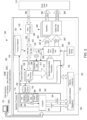
- FIG. 1 is a block diagram of an example of a relay and metering test instrument in communication with a testing computer and one or more pieces of power equipment under test.
- the relay and metering test instrument 100 is in communication with a testing computer 102 executing testing software 104 stored in a memory circuitry 106.
- the testing software 104 may be executed by processor circuitry 108 on the testing computer 102 to provide a test technician with a user interface to the relay and metering test instrument.
- the testing computer 102 may be, for example, a laptop personal computer, a tablet, a mobile phone, or any other device or system having a user interface, such as a keyboard, display screen, and the like, which is configured for bi-direction wireless or wired communication with the relay and metering test instrument 100.
- the relay and metering test instrument 100 may provide diagnostic testing of equipment under test 112, which may be protective equipment such as relays, transformers, meters and any other equipment within an electric power system used to monitor and safeguard operation.
- protective equipment such as relays, transformers, meters and any other equipment within an electric power system used to monitor and safeguard operation.
- Protective equipment of the type tested with the relay and metering test instrument 100 is referred to herein as "protective relaying equipment” or “protective relay(s).”
- Diagnostic testing with the relay and metering test instrument 100 is not limited to digital, mechanical and/or electromechanical protective relays, since other monitoring devices and systems including instrument transformers, such as current/potential transformers, power system disturbance detection and/or analysis devices, and other types of systems/devices may detect and/or take appropriate action when abnormal and/or intolerable power system conditions are present.
- the diagnostic testing performed by the relay and metering test instrument 100 may include viability/assessment testing such as relay scheme verification, digital logic testing, detection of predetermined conditions, confirmation of operation, accuracy assessment, timing, and functionality testing.
- the relay and metering test instrument 100 may be used by power utilities and others to protect equipment and facilities related to the transmission, distribution and usage of AC or DC electrical power.
- protective relaying equipment may monitor current and voltage waveforms being generated, conducted and/or used by the equipment or facilities being protected.
- such protective relaying equipment may extract characteristics from the monitored waveforms, such as the amplitude, phase angle and frequency of those waveforms' AC components.
- Such protective relaying equipment may interpret the extracted characteristics to trigger actions such as opening switches or circuit breakers to isolate protected equipment or facilities from electrical power, in order to avoid or minimize damage or undesirable conditions.
- actions may be referred to herein as "operation" of a relay output, such that an action triggered by a protective relay, may be described as a circumstance where the relay has "operated” or "operates.”
- the relay and metering test instrument 100 may test aspects of protective relaying equipment by generation of current and voltage waveforms simulating conditions that could be experienced/observed by the protective relaying equipment in various scenarios. Such scenarios, may include, for example, fault conditions that occur due to short circuits, broken conductors or damaged equipment.
- Current and voltage waveforms may be emitted by the relay and metering test instrument 100 in the form of electrical current and voltage (using voltage amplifiers and current amplifiers), or as digital data such as IEC 61850 Sampled Values for receipt by the protective relaying equipment under test.
- the relay and metering test instrument 100 may monitor one or more outputs of the protective relaying equipment to, for example, determine whether the equipment under test triggered an event, such as the opening of a breaker in a correct and timely manner.
- "Outputs" of a protective relay(s) may include physical outputs, such as a contact closure(s) or change in an output voltage or current, or may be a digital output such as setting one or more bits in a data stream, or otherwise digitally communicating to trigger an event.
- Generation of current and voltage waveforms by the relay and metering test instrument 100 may include real-time control and adjustment of dynamic parameters used to define each of the waveforms being generated. Parameters for each waveform output may include: amplitude (volts or amperes); phase angle, relative to a reference; and frequency. For complex waveforms generated by the relay and metering test instrument 100, such as those involving harmonics, multiple sets of amplitude, phase and frequency can be used by the relay and metering test instrument 100 to generate multiple waveforms. The relay and metering test instrument 100 may sum the multiple waveforms generated to produce a combined waveform for output to, for example, protective relay(s).
- the parameters may be altered by the relay and metering test instrument 100 in various ways during a test.
- the relay and metering test instrument 100 may generate a test waveform having a smoothly ramping parameter, such as a voltage.
- a waveform may be generated during testing that "ramps" from 50 Volts to 100 Volts smoothly, where smoothly, in this example is a constant and linear rise in voltage at a rate of 10V per second until the protective relay operates.
- the relay and metering test instrument 100 may generate a waveform having a stepping a parameter.
- a parameter such as frequency might be adjusted to 50 Hz, 50.1 Hz, 50.2 Hz, and so on, with each frequency persisting for defined time, such as 1/10 th of a second.
- the relay and metering test instrument 100 may generate a waveform having a pulsing parameter.
- the pulsing may be similar to ramping except that the parameter goes to some fixed predetermined value (such as zero amplitude) for a defined period of time between values, rather than stepping directly from one value to the next.
- the relay and metering test instrument 100 may vary parameters using complex algorithms, such as non-linear ramps and binary searches to generate the test waveforms.
- the relay and metering test instrument 100 may evaluate the timing accuracy of the protective relay's operation during such testing. Accordingly, the relay and metering test instrument 100 performs parameter-adjustment in a way that results in precisely-timed changes to the generated waveforms.
- the example relay and metering test instrument 100 in FIG. 1 includes application processor circuitry 116, real-time processor circuitry 118, memory circuitry 120, and input/output processor circuitry 122.
- the application processor circuitry 116 may manage and control the functional operation of the relay and metering test instrument 100.
- the application processor circuitry 116 may include executable firmware that provides a communication interface with the testing computer 102.
- the executable firmware may provide an interface with the memory circuitry 120.
- the memory circuitry 120 may be a shared or arbitrated memory that is accessible by the real-time processor circuitry 118 and the input/output processor circuitry 122.
- the real-time processor circuitry 118 may be in communication with the input/output processor circuitry 122 via one or more communication busses 124.
- the application processor circuitry 116, real-time processor circuitry 118, and input/output processor circuitry 122 may be separate, distinct, and independently operational processor circuitry.
- the application processor circuitry 116 may be a quad core ARM
- the real-time processor circuitry 118 may be a dual core ARM
- the memory circuitry 120 may be a DRAM
- input/output processor circuitry 122 may include an FPGA.
- the real-time processor circuitry 118 administers the diagnostic tests performed by the relay and metering test instrument 100 by, among other things, coordinating with the input/output processor circuitry 122 over the communication bus 124 to generate test waveforms during a test state. Operation of the real-time processor circuitry 118 to perform a test routine 130 in a test state may be based on execution of any of a number of different and independent test routines 130 stored in the memory circuitry 120. Each of the test routines 130 may include one or more different testing stages 132 that together represent at least part of a respective test state.
- an overcurrent protective relay may be cycled through the test states of pre-fault condition where balanced current conditions are simulated, a fault condition where a three-phase or single-phase fault current conditions are simulated, and a post-fault condition where balanced current conditions are again simulated after an event, such as opening a circuit breaker to eliminate the fault.
- one or more test routines 130 may be executed.
- the relay and metering test instrument 100 may include any number of test routines. Accordingly, any number of test routines 130 may be stored in the memory circuitry 120, with each of the test routines 130 having any number of respective testing stages 132. Pointers 136 may be stored in the memory circuitry 120. The pointers 136 may identify a location of a respective test routine 130. The test routines 130 may be generated and stored in the memory circuitry 120 in an overlay database 140 by the application processor circuitry 116. The application processor circuitry 116 may also generate and store the pointers 136 in the memory circuitry 120 in a pointer database 142.
- the memory circuitry 120 may be a shared memory, such as a random-access memory (RAM) that is accessible by the application processor circuitry 116, the real-time processor circuitry 118 and the input output processor circuitry 122. Execution, by the real-time processor circuitry 118, of testing stages 132 in a respective overlay 130 may be coordinated with operation of the input output processor 122.
- RAM random-access memory
- the application processor circuitry 116 may receive, from the testing computer 102, a source code state program selected by a user, and operational parameters received as inputs from the user.
- the application processor circuitry 116 may compile the source code state program and the operational parameters into a test routine 130.
- the test routine 130 may be stored in the overlay database 140 in the memory circuitry 120 with a number of other test routines 130, which are accessible by the real-time processor circuitry 118.
- the application processor circuitry 116 may generate pointers 136 identifying locations of respective test routines 130.
- the pointers 136 may be stored in the pointers database 142 in the memory 120 to be accessible by the input/output processor circuitry 122.
- the real time processor circuitry 118 may selectively execute test routines 130 according to pointers 136 provided by the input/output processor circuitry 122.
- the pointers 136 may be provided by the input/output processor circuitry 122 at the time input/output processor circuitry 122 instructs the real time processor circuitry 118 to transition to another test routine 130.
- the input/output processor circuitry 122 may generate waveforms for output to the equipment under test 112.
- the waveforms may be sinusoidal waveforms generated by the input/output processor circuitry 122 from waveform generation parameters calculated by the real-time processor circuitry 118.
- the input/output processor circuitry 122 may receive and process input triggers received from the equipment under test 112. The input triggers may be used by the input/output processor circuitry 122 to control the respective test routines 130.
- the equipment under test may be, for example, one or more protective relays that sense voltage and/or current and output an output signal.
- an overvoltage or overcurrent relay may output an over voltage/overcurrent indication, such as a digital output, a contact closure, or an analog output.
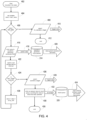
- FIG. 2 is an example of an operational flow diagram for a relay and metering test instrument 100.
- the operation starts with the application processor circuitry 116 controlling functional operation of the relay and metering test instrument 100 (202) to perform a test routine in a test state.
- Control of functional operation may be performed with firmware executed by the application processor circuitry 116 to, for example, manage communication, control the user interface, compile source code and operational parameters(s), manage operational parameters, manage database(s), manage data storage in the memory circuitry 120, and the like.
- the application processor circuitry 116 may receive a source code state program selected by a user, and operational parameters received as inputs from the user as part of a complete state sequence (204).
- the complete state sequence may include state definitions for each state or test state.
- the test states may be a series of states in the state sequence of a complete test. Each of the states may include transitions between states.
- the source code state program may be one of a number of different source code files, such as a C-language source code files, representative of a portion of a respective state definition in a state.
- the state definitions of the respective states in a state sequence may also include, for example, waveform generation parameters such as amplitude, phase angle, frequency, for test state functionality, which is not part of the test routines being controlled by the real-time processor 118.
- Other example test functionality that may be included in the state definitions includes maximum duration for the state; index(s) providing transition to another state if a maximum duration is reached; other state index values that may become active under pre-specified conditions; an "inherit" Boolean value, which if true causes any value not defined for a given state to remain as it was in the previous state rather than changing to a default value; definition(s) of outputs such as binary/logic/contact outputs that may be set to a particular state during the particular state; sets of waveform sample data that may be played back, for cases where, for example, simple sinusoidal waveforms aren't appropriate; trigger definitions, indicating which inputs and other events will be processed into numbered trigger events; definition(s) of state transitions that may occur if
- the source code state program may be waveform parameter-alteration algorithms, such as smooth ramp, stepped ramp, pulsed ramp, binary search and multiple-parameter ramp source code used to generate waveform parameters.
- Operational parameters received as inputs from the user with the source code state program may be static operational parameters corresponding to the selected source code state program.
- the static operational parameters may include, for example, start and end parameters such as thresholds, setpoints, time periods and other variables that configure aspects of the respective test routine.
- the static operational parameters may also include "trigger" selections, which, as further described elsewhere, are related to the way events are communicated between the input/output processor circuitry 122 and the real-time processor circuitry 118 over the communication bus 124.
- any of the number of different source code state program files may be available and selectable by a user via the user interface provided on the testing computer 102.
- one or more of the static operational parameters for a selected source code state program may be input via the user interface in the testing computer 102.
- the application processor circuitry 116 may compile the source code state program and the static operational parameters into a test routine 130 (206).
- the test routine 130 may be, for example an object file having a header that includes the static operational parameters. In other examples, other types of file structures may be used.
- the test routine 130 may be created by the application processor circuitry 116 firmware in response to commands from the user's testing software executed on the test computer 102.
- the testing software executed on the test computer 102 may provide a message containing operational parameter names and values.
- the application processor circuitry 116 may package the parameter names and values in a predetermined format. For each operational parameter, the application processor circuitry 116 may generate an "undef" macro, to undefine a default value that's defined in the test routine 130. In this way, any static parameters the user's test software and the test computer 102 provides may be used, and any parameters not provided may have default values.
- the application processor 116 may then "re-define" each parameter to set the value of the static parameter according to the value provided in the test routine 130.
- Values may be presented in the test routine 130 as static parameters in an appropriate form to initialize a variable of the appropriate type for the particular parameter (integer, double value, boolean, etc.). Conversion functions may be defined in a header to scale values according to a type of the parameter. That way parameter initializers such as amps(10) or Hz(60) result in values that may be typed and scaled correctly.
- test routines may expect voltages to be in fixed-point integer format with 16 fractional bits, the conversion function may multiply the given voltage value by 65536 and retain only the integer portion of the result. If the user's test software sends an incorrect parameter name, that parameter may still get generated as undef/define static parameter, but those parameters may be ignored by the test routine processor circuitry 118.
- specific static operational parameters such as in the example shown below: arrays in the test routines code may be sized to allow simultaneous ramping of up to four separate parameters.
- input trigger 5 may be used to sense the operation of an equipment under test, such as a relay being tested.
- the application processor circuitry 116 may compile the source code and static parameters to generate an object file.
- the object file may then be stored the test routine 130 in the memory circuitry 120 (208).
- the test routine 130 may be stored with any number of other test routines 130 in the memory circuitry 120.
- a memory location in the memory circuitry 120 of the test routine may be accessible by the real-time processor circuitry 118.
- the real-time processor circuitry 118 may selectively and independently execute the test routine 130 or one of the other test routines 130 to perform a plurality of respective testing stages 132 when directed by the input/output processor circuitry 122.
- Writing of the test routine 130 to the memory circuitry 120 may be executed by the application processor circuitry 116 while the real-time processor circuitry 118 is executing one of the other test routines 130.
- the just compiled object file may be loaded as the test routine 130 into a RAM area in the memory circuitry 120 that's always accessible to the application processor circuitry 116 and the real-time processor circuitry 118.
- the specific RAM area where the just compiled object file is stored as the test routine 130 may only get modified while the real-time processor circuitry 118 is not accessing that specific RAM area (between tests, or while generating another test routine other than the one that's being updated with the just compiled object file).
- the real-time application processor 118 may update its function pointer when a new pointer 136 is provided by a state sequencer included in the input/output processor circuitry 122.
- the state sequencer may obtain the pointers 136 for all the test routines from another shared RAM area of the memory circuitry 120.
- the application processor circuitry 116 may generate a pointer 136 to the memory location in the memory circuitry 120 where the test routine is stored (210).
- the pointer 136 may be stored in the memory circuitry 120 by the application processor circuitry 116. Different pointers 136 may also be stored in the memory circuitry 120 for each of the other test routines stored in different memory locations in the memory circuitry 120.
- the input/output processor circuitry 122 and/or the real-time processor circuitry 120 may dictate whether the test state being performed by execution of the test routine 130 is complete (216). Completion of the test state may be based on, for example, a predetermined input signal received by the input/output circuitry 122, an elapsed period of time determined by the real-time processor circuitry 120, or some other criteria. If the test state is not complete, execution of the test routine 130 in one or more testing stages 132 may continue. If the test state is determined to be completed, the transition between test routines 130 may be directed by the input/output processor circuitry 122 by providing commands to the real-time processor circuitry 118 that include a pointer 136 to the next test routine 130 (218).
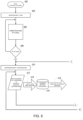
- FIG. 3 is a block diagram of an example relay and metering test instrument 300 in communication with a test computer 102 and an equipment under test 112.
- the relay and metering test instrument 300 includes the application processor circuitry 116, the real-time processor circuitry 118, the memory circuitry 120, and input/output processor circuitry 122 similar to the relay and metering test instrument 100 discussed with reference to FIGs. 1 and 2 .
- the features and functionality of the relay and metering test instrument 100 are similar.
- the application processor circuitry 116 includes a compiler 302 for compiling the source code state programs and operational parameters received as selections included in a state sequence 303 from the test computer 102.
- the state sequence 303 may be prepared by a user of the relay and metering test instrument 300 using the test computer 102 and provided to the relay and metering test instrument 300.
- the user may create a test sequence 303 that includes a series of states as one or more test states 303A having state definitions 303B.
- Each of the state definitions 303B may include, among other things, one or more source code state programs 303C.
- the source code state programs 303C may be compiled as object code, which is stored as a test routine 130 executable within a test state 303A of a state sequence 303.
- the compiled object code of a test routine 130 may be stored in the test routine database 316 as illustrated by the compiled code line 301.
- the application processor circuitry 116 also includes a communication interface circuitry 304, a user interface circuitry 306 and a memory manager circuitry 308.
- the communication interface 304 may include functionality providing wired or wireless communication with the test computer 102.
- communication with the real-time processor circuitry 118 and the input/output processor circuitry 122 may be handled via the communication interface 304.
- the user interface 306 may provide functionality to drive visual indicators, such as lights, readouts, and/or displays and the like, and receive user input signals such as button press signals, touch screen signals, images, and the like which may be initiated by a user from hardware such as buttons, switches, a touch screen, a camera, a sensor or any other mechanical user interface included on the relay and metering test instrument 300.
- the memory manager circuitry 308 may manage arbitration of the shared memory circuitry 120, and may include database management capability, multi-level secure access management for authorized users and the like.
- the real-time processor circuitry 118 may include executive code 312 to manage execution of the test routines 130.
- the real-time processor circuitry 118 includes a waveform generation parameters buffer 314 for waveform generation parameters generated and altered by a test routine being executed during a test state 303A.
- Waveform generation parameters may be dynamically calculated by a respective test routine 130 in one or more testing stages 132 of the test routine 130.
- the waveform generation parameters are phasor values (amplitude, phase angle, frequency, and the like).
- the waveform generation parameters may be dynamically changed or adjusted by the real-time processor circuitry 118 during a test state 303A, during a testing stage 132, when transitioning between testing stages 132 or when transitioning between test routines 132.
- the waveform generation parameters 314 may be dynamically changed as the relay and metering system proceeds through the test routine 130 based on predetermined times, logic conditions and/or events occurring during the test routine 130 and/or during the test state 303A.
- the waveform generation parameters 314 may be dynamically changed by receipt of dynamic operational parameters that are input by a user, such as in the test computer 102.
- the executive code 312 may be a firmware program executable with the real-time processor circuitry 118 to manage activation, deactivation control and execution of the test routines 130.
- Each test routine 130 may reside an overlay, which becomes active when appropriate based on the sequencing of test states 303A in a respective test sequence 303 during a test. Sequencing of the test states 303A in a test sequence 303 may be controlled by the input/output processor circuitry 122 based on, for example, triggers and timers to transition between the test states 303A and/or between the test routines 130 within a test sequence 303 using pointers 136 stored in the memory circuitry 120.
- the memory circuitry 120 may include a test routines database 316, a pointers database 318 and a report queue 320.
- the test routines database 316 may store the test routines 130 in association with one or more memory locations 322.
- the source code state programs, which are selectable by a user as part of one or more test states 303A in a state sequence 303, and compiled to generate the test routines 130 may also be stored in the test routine database 316.
- the stored source code state programs may be provided to the test computer 102 for selection by a user when creating a state sequence 303.
- the source code state programs may be stored in the test routine database 316 at the time the firmware executable with the application processor circuitry 116 was developed, tested and released. Alternatively, or in addition, at least some of the source code state programs may be stored in the test computer 102 or accessed with the test computer 102 for selection for inclusion in a test state 303A of a state sequence 303.
- the pointers database 318 may include the pointers 136 providing a memory location 322 of each of the test routines 130 in the test routine database 316.
- the input/output processor circuitry 122 may access the pointers database 318 according to a respective test state 303A to extract corresponding pointers and direct the real-time processor circuitry 118 to execute different test routines 130 as dictated by operation of the test sequence 303 when running through a series of test states 303A during a test. For example, to transition between first and second test states, the input/output processor circuitry 122 may retrieve and provide, to the real-time processor circuitry 118, a respective pointer to a memory location 322 of a test routine 130 in order to direct execution by the real-time processor circuitry 118.
- the report queue 320 may store real-time test result values as each test routine 130 is executing testing stages 132 in a particular test state 303A for equipment under test. For example, in a test routine 130 for a double ramp, in which a waveform ramps down until a protective relay drops out and then ramps back up again until the protective relay picks up, the parameter values of the waveform at the time the relay dropped out may be stored and the parameter values of the waveform at the time the relay picks up may be stored as testing stage result values of the respective testing stages 132.
- the testing stage result values may be calculated, reported, interpreted and stored by the real-time processor circuitry 118. Calculation, reporting and interpretation of the testing stage result values may include analysis of differences in expected operation of the equipment under test vs.
- the real-time processor circuitry 118 may capture, calculate, report, interpret and store time-based situational aspects in the report queue 320 as a test state 303A unfolds, as illustrated in FIG. 3 by a test report values line 325.
- the time-based situational aspects may be captured, calculated and stored while testing stages 132 of a particular test routine 130 is executed and input(s) and output(s) of the input/output processor circuitry 122 are occurring.
- dynamic operational parameters may also be conveyed by the application processor 116 and stored in memory circuitry 120, such as in registers in the test routine database 316.
- the registers containing dynamic operational parameters may be updated based on new operation parameters input by a user during a test in which a test routine 130 is executing.
- the user interface of the testing computer 102 may allow a user to manually adjust a ramp rate of a waveform during ramping of the waveform by a ramping test routine 130 by changing dynamic operational parameters using push buttons.
- the application processor circuitry 116 may update the storage location of the dynamic operational parameters of the ramping test routine 130 with a new operational parameter input by the user during execution of the ramping test routine 130 as illustrated with the dynamic line 324.
- the real-time processor circuitry 118 may retrieve the newly stored operational parameter from the memory circuitry 120 during execution of a testing stage 132 included in the ramping test routine 130.
- the dynamic operational parameter may be retrieved from one or more register(s) 326 in the memory circuitry 120, by the real time processor circuitry 118 while executing one or more testing stages 132 of the ramping testing routine 130.
- the registers 326 may be one or more predetermined blocks of memory storage location(s) that are writeable by the application processor circuitry 116 and readable by the real-time processor circuitry 118 during execution of the ramping test routine 130 by the real-time processor circuitry 118.
- the input/output processor circuitry 122 may include a state sequencer 332, a waveform sample generator 334, and a sample timing generator 336.
- the state sequencer 332 may control progression through a series of the test states 303A in a state sequence 303.
- the state sequencer 332 may also identify the respective pointer 136 in the pointers database 318 for a respective test routine 130 included in the test state 303A that should be executed as part of the test.
- the state sequencer 332 may extract and pass the pointer 136 to the real-time processor circuitry 118. In the example of FIG.
- the pointer 136 for the test routine 130 in the current test state 303A is passed to the real-time processor circuitry 118 via a function pointer line 338, and a test state number of the current test state 303A is passed to the real-time processor circuitry 118 via the state transition line 339.
- the function pointer line 338 carries the pointer for a test routine 130 in the second test state 303A, and the state transition line changes from the first test state 303A to the second test state 303B, such as from #1 to #2.
- the state sequencer 332 also includes a trigger manager 333 to manage incoming and outgoing triggers 344 as illustrated by arrows in FIG. 3 .
- Outgoing triggers 344 from the state sequencer 332 may be provided to a respective test routine 130 to, for example, initiate some action or change in the testing stages 132 of a test routine 130.
- a waveform may be ramping in a first direction through one or more testing stages 132 until the test routine 130 receives an output trigger from the state sequencer 332 to execute one or more testing stages 132 to reverse the direction of the ramp to a second direction.
- Incoming triggers to the trigger manager 333 may be provided from input devices 346 upon receiving events 348 from equipment under test 112.
- Input devices 346 may be opto-isolators, A/D converters, dry contacts, wet contacts and/or any other signal conversion or conditioning device or system receiving signals from an equipment under test 112.
- Events 348 may be a predefined condition, such as, for example, a contact closure in a protective relay, or a voltage reaching a predetermined threshold, or the like.
- Example events include an overcurrent protective relay closing a contact when an overcurrent condition is reached, or a frequency protective relay sensing a frequency and providing a representative signal outside a predetermined acceptable range.
- Incoming triggers 344 may also be provided to the state sequencer 332 by testing stages 132 in the test routines 130. For example, a test routine 130 executing in a testing stage 132 may generate one or more incoming triggers 344 related to the progress of the testing stage 132. For example, one or more incoming triggers 344 may be generated when a protective relay fails to sense an event when a generated waveform reaches a predetermined condition.
- Each of the incoming triggers 344 may be identified by a unique identifier known to the state sequencer 332.
- each of the outgoing triggers provided to the real-time processor circuitry 118 may be identified by a unique identifier so that the respective test routines 130 may receive, process and react appropriately to outgoing triggers received from the state sequencer 332.
- triggers 344 to and from the test routines 130 may be stored in the registers 326 or other predetermined storage locations in the memory circuitry 120 that are accessible by both the real-time processor 118 and the input/output processor 122.
- the interface between the trigger manager 333 and the test routine 130 may remain intact and fully operational.
- pre-determined indexing and predetermined assigned storage locations indexed to the triggers may be used such that changes to the functionality of the state sequencer 332 and/or the trigger manager 333 may be avoided. Accordingly, more extensive updates to the firmware supporting the state sequencer 332 and the trigger manager 333 as well as the other functionality outside the test routines 130 may be avoided when one or more of the test routines 130 are updated.
- Determination by the state sequencer 332 of a beginning and an end of respective testing stages 132 and/or respective test routines 130 and or test state 303A may be rules-based determination using predetermined rules that align with the triggers 344 and trigger conditions.
- the trigger conditions may be a current status of incoming triggers 344 received by the state sequencer 332 and outgoing triggers 344 generated by the state sequencer 332.
- the state sequencer 332 may receive triggers 344 from any number of input devices 346 and testing routines 130.
- each of the input devices 346 may generate one or more separate and distinct incoming triggers 344 according to event(s) 348.
- the waveform sample generator 334 may receive waveform generation parameters 314 from a particular testing routine 130 and generate waveforms therefrom. For example, the waveform sample generator 334 may receive phasor values for one or more waveforms, which may be summed to generate more complex waveforms, such as waveforms with superimposed harmonics, or other complex features.
- the waveform generation parameters 314 may be dynamically changed by the testing stages 132 of the test routine 130 during a test as part of the test state. In addition, the waveform generation parameters 314 may be dynamically changed during testing stages 132 by receipt of dynamic operational parameters that are input by a user and stored in the registers 326.
- the waveform generators may be receiving changing phasor values, such as amplitudes, phase angles, frequency and the like that coincide with the particular testing stage 132 of the test routine 130. Since the real-time processor circuitry 118 is also receiving triggers, pointers, and state transitions, time synchronization of waveform changes may be precisely controlled. Parallel processing of the generation of waveform generation parameters and processing of triggers, pointers, and state transitions in the testing stages 132 avoids sequential processing and related lag time and delays, and allows for precise timing of dynamic adjustments of the generated waveform samples.
- the waveform sample generators 334 may output waveform sample values 352 to any number of different amplifiers 340 included in the input/output processor circuitry 122 as illustrated by arrows.
- the amplifiers 340 may be current amplifiers, voltage amplifiers or both.
- the waveform sample values 352 may be used to drive the amplifiers 340 to output desired current and voltage sine waves 356 to simulate desired test conditions for equipment under test 112.
- the waveform sample values 352 may be provided to a digital data generator 342.
- the digital data generator 342 may convert the waveform sample values 352 to digital information.
- the digital information representing the waveform sample values 352 may be organized in data packets 358 for transmission over a network to the equipment under test 112.
- Amplifiers 340 and digital data generator 342 and transmission via a network are representative ways of conveying the waveform sample values. Other conveyance platforms may be used to provide the equipment under test 112 with simulation of different waveforms for purposes of testing.
- the sample timing generator 336 may be a time source to coordinate operation of the real-time processor circuitry 118 and the input/output processor circuitry 122.
- the operation of the test routines 130 may be based on receipt of the interrupts.
- the test routine 130 may enter a different testing stage 132 each time an interrupt is received.
- the test routine 132 may, for example, remain in a testing stage 132 for a predetermined number of interrupts, until either a trigger is received or a determined number of interrupts are received, or any other timing/logic to provide the desired test situation/scenario for a test state 303A.
- Desired test situation/scenarios may include, for example, the correct waveform generation parameters 314, generation of trigger(s) 344 in synchronism with the other processor circuitry, and the like.
- the interrupts not only do the interrupts cause the test routine 130 to execute test stages 132, or take no action, the interrupts also provide synchronization with operations related to the application processor circuitry 116 and the input/output processor 122. For example, execution of a respective different testing stages 132 of a test routine 130 to generate waveform generator parameters may be synchronized with the waveform sample generators 334 using the interrupts.
- sample pulses may be output as a pulse train on a sample pulses interrupt line 354 to operate as an interrupt for the test routine 130.
- the interrupts received by the real-time processor 118 may cause a presently executing test routine 130 to transition to another testing stage 132, poll registers 126, check for triggers 344 from the state sequencer 332, pause and take no action, and the like.
- the interrupts may cause the real-time processor 118 to initiate execution of the test routine 130 to dynamically generate waveform sample values with the waveform sample generator 334.
- the sample timing generator 336 may generate a 48 kHz pulse train.
- the sample timing generator 336 may be synchronized or disciplined to a time source.
- a test routine 130 may respond to an interrupt that occurs at the waveform sample generation rate (for example 48 kHz), by performing calculations based on a count of the interrupts received from the sample timing generator on the sample pulses line 354.
- the real-time processor circuitry 118 may execute the test routine 130 to dynamically calculate waveform generator parameters, such as amplitude, phase angle and frequency parameters, according to the testing stage 132 and/or the phase of a test state being executed and/or dynamic operational parameters received as inputs from a user.
- the waveform generator parameters may be written into the waveform generation parameter buffer 314 and stored in, for example, registers in the input/output processor circuitry 122.
- the input/output processor circuitry 122 may include sample generation logic in the waveform sample generator 334, which may use the parameters to generate waveforms as waveform sample values 352.
- the test routines 130 may respond to changes in the states of outgoing triggers or incoming triggers.
- Triggers 344 may, for example, be in the form of trigger bits, which may be a single bit that toggles to indicate a change, or more than one bit that provides a trigger message indicative of the change.
- the outgoing triggers may be provided by the state sequencer 332 of the input/output processor circuitry 122.
- the outgoing triggers may be bits that responsively change state during a test state 303A, such as, for example, in response to a relay operation.
- Each test routine 130 may use the outgoing triggers in any desired fashion. For example, a binary-search test routine 130 may decide whether a given waveform pulse or waveform stop threshold should be higher or lower than the previous one, based on whether the equipment under test 112 operated during the previous pulse or step, and what was the nature of the operation.
- the real-time processor circuitry 118 may also produce triggers, such as "trigger" bits, by writing triggers 344 to registers accessible to state sequencer 332 in the input/output processor circuitry 122.
- triggers such as "trigger” bits
- Such input triggers from the real-time processor circuitry 118 may indicate, for example "relay operated at the correct time”, “relay operated at an inappropriate time”, or "relay did not operate within the allowed time limit”.
- the state sequencer 332 may, for example, use the incoming triggers from the real-time processor circuitry 118 to decide whether to direct the real-time processor circuitry 118 to make a transition from one test state 303A to another test state 303A during a state sequence 303 or change testing stages 132 within the test routine 130 of the present test state 303A.
- the real-time processor circuitry 118 may also write report values to the report queue buffer 120, which is accessible to application processor circuitry 116.
- the application processor circuitry 116 may provide the report values to the test computer 102 as result data. For example, if a phase angle of a simulated waveform is ramped from 90 to 120 degrees, and a phase angle protective relay operates at a test stage 132 when the phase angle is 100 degrees, the test routine 130 may write 100 degrees as a result value in the report queue buffer 120 to that test stage 132 and/or for the test routine 130.
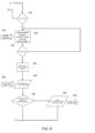
- FIG. 4 is an operational block diagram of an example of execution of a test routine.
- the test routine 130 is a ramped test routine executed by the real-time processor circuitry 118 to provide a ramped waveform via the waveform sample generator 334.
- the ramped test routine 130 sets a waveform amplitude to a start value, then enters one or more different test stages 132 and ramps the amplitude of the waveform up at a defined rate until either the connected equipment under test, such as a relay, operates or the ramp reaches a defined end value.
- the example operation begins when the ramped test routine is executed by the executive code 312 operating as firmware in the real-time processor circuitry 118.
- the real-time processor circuitry 118 is directed to transition to a test state 303A that includes the ramped test routine 130 by the input/output processor circuitry 122 providing a current state on the current state line 338 and a state transition number on the state transition line 339 (402).
- the controlled waveform generation parameter values are set equal to the static operational parameter values (start_ value) included in the header of the object file when the source code state program 303C representing the ramp test routine 130 was compiled by the application processor circuitry 116 (404).
- the start ramp value may be a waveform amplitude, such as 50 Vac having a ramp of, for example, 1 volt/second, to an end ramp value, such as 80 Vac.
- the real-time processor circuitry 118 determines if the ramp value is greater than a value (end _value) at which the equipment under test is expected to operate (406). If yes, the real-time processor circuitry 118 executes the ramp test routine 130 to assert that the equipment under test did not operate (no_operation_trigger) (408), sends a trigger output from the real-time processor circuitry 118 for receipt as a trigger input to the state sequencer 332 (410), and ends execution of the ramp test routine 130.
- the real-time processor 118 may generate waveform generator parameter(s) (416), and provide to the input/output processor circuitry 122 via the waveform generation parameters buffer 314 (418).
- the input/output processor circuitry 116 may, for example, extract the waveform generation parameters from a memory location, and provide the parameters to the waveform sample generator 334, which provides waveforms or waveform samples to the equipment under test (420).
- the real-time processor circuitry 118 may then wait for the next sample-interval interrupt from the sample timing generator 336 (422).
- the real-time processor circuitry 118 may determine if the event has occurred upon receipt of the sample interrupt by checking if an output trigger from the state sequencer 332 has been provided as an input trigger to the real-time processor (424). If yes, the real-time processor circuitry 118 executes the ramp test routine 130 to assert that the equipment under test did operate (operation_trigger) (426), and sends a trigger output from the real-time processor circuitry 118 for receipt as a trigger input to the state sequencer 332 (428). In addition, the real-time processor circuitry 118 calculates and records test result values including the as-ramped waveform value and the amplitude value at which the equipment under test, such as a protective relay operated (430).
- the test result values including the as-ramped value may be provided to the report queue 320 (432).
- the testing computer 102 may read test results from the report queue 320 (434). Alternatively, or in addition, the test results may be pushed to the testing computer 102. Execution of the ramp test routine 130 may cease (436).
- the real-time processor 118 may increment the amplitude value of the waveform by the ramp rate (438) by providing waveform generation parameters to the waveform sample generator 334.
- the real-time processor 118 may determine if the increment caused the amplitude value to exceed the expected amplitude that should cause the equipment under test to actuate and the operation may proceed to repeat some of the previously discussed steps.
- FIG. 5 is a block diagram of another example operation of a test routine for a piece of equipment under test.
- the equipment under test is described as a relay, however, in other examples, other equipment may be tested.
- the test routine 130 of this example when executed by the real-time processor circuitry 118, is a multi-ramp test routine that may execute in parallel a number of waveforms, such as simple ramps, smoothly increasing or decreasing a value for each ramp. The multiple ramp waveforms may be executed in parallel until either the equipment under test, such as a relay being tested, operates, or the user's testing software on the testing computer 102 requests a transition out of the current state.
- test result value(s) may be enqueued in the report queue 320 for each ramp, namely the as-ramped value at the time when the relay operated is enqueued in the report queue 320. If the relay does not operate, no result values are enqueued.
- Each ramp optionally includes a trigger index, which may be asserted when the relay operates. In this way the test state may be structured so that a state transition occurs at the time the relay operates for any one of the ramps.
- the source code state program which is compiled into the test routine 130 may include one or more header files that are parameter definition files generated by the application processor circuitry 116.
- the header files included in the test routine 130 may include conversion functions, such as a voltage conversion function, and the like.
- the test routine 130 may also include standardized library headers, to make use of standardized library functions and classes.
- the headers of the test routine 130 may define one or more special trigger index values, such as a special trigger index value to monitor for relay operation.
- the header file(s) may define default values for some or all static operational parameters. These default values may be used for any static operational parameter that is not defined in the header file.
- Each ramp may also operate with a set of dynamic parameters, which may be dynamically adjusted by a user during a test while the test routine is executing.
- Static operational parameters are set to fixed values from the header file(s) before the test routine is executed.
- each of the ramps may include as dynamic operational parameters a start value, an end value and a ramp rate for a value, such as amplitude, being ramped.
- the ramp rate may be positive or negative, for upward or downward ramps.
- the respective ramp may stop when it hits either the start value or the end value such that the value of the respective ramp no longer changes.
- the ramp may be re-started at that new start value.
- example operation begins when the multi-ramp test routine is executed by the executive code 312 operating as firmware in the real-time processor circuitry 118.
- the real-time processor circuitry 118 is directed to transition to a test state of the multi-ramp test routine 130 by the input/output processor circuitry 118 by providing a current state on the current state line 338 and a state transition number on the state transition line 339 (502).
- the real-time processor circuitry 118 sets a flag indicative of operation of the equipment under test, such as a relay, to false (504).
- the real-time processor circuitry 118 may then identify the number of ramps (N) from static operational parameters included in the header file, and initialize a ramp state of the N ramp states using initial dynamic parameters (506).
- the initial dynamic operational parameters may be extracted from registers 326 in the test routine database 316.
- the dynamic operational parameters may be stored in other ways in memory circuitry 120.
- the dynamic operational parameters for each ramp N are upper limit, lower limit, and ramp value, where the ramp value may initially be equal to the lower limit.
- the real-time processor circuitry 118 may determine if all N of the ramps identified by the static operational parameter are initialized (508), and if not, initialize the remaining ramp states for the N ramps (506).
- the state information of each N ramp may be retained in a structure, such as an array, that is updated and monitored by the multi-ramp test routine 130.
- the array ramp state may be initialized as state information for each of the "N" ramps.
- maximum_ramp_count structures each containing: An “outputValue” which may be a parameter value written to a waveform generation parameter.
- the “outputValue” may be calculated according to the ramp parameters "mostRecentLowerLimit,” and “mostRecentUpperLimit,” where copies of lowerLimit and upperLimit dynamic parameters may be used to detect when those parameters change.
- the dynamic parameters used may be a Dynamic Parameter RAM block, which is an array with one structure per simultaneous ramp (maximum_ramp_count elements). Values may be dynamically changed by the application processor circuitry 116 while this test routine is executing.
- Each structure may include: waveformIndex (identifies the waveform for which a generation parameter is to be ramped), destination (which parameter to ramp: amplitude, frequency or phase), lowerLimit, upperLimit, rampRate (ramping limits and rate).
- the real-time processor circuitry 118 may set a flag indicating whether the relay operated in the previous sample interval (in order to later determine whether the input state changed) (510). The real-time processor 118 may then generate waveform generator parameters (512) for each of the respective N ramps using a ramp index and destination.
- the ramp index may be an identifier of a respective ramp N
- the destination may be a waveform generator 334, which will output the respective waveform sample values 352 ( FIG. 3 ).
- the waveform generator parameters may be provided to the input/output processor circuitry 122 (according to the index and destination) via the waveform generation parameters buffer 314 (514).
- the waveform generator parameters such as amplitude, phase or frequency, for each index may be retained in the buffer 314 between sample intervals, so the real-time processor circuitry 118 may detect when these parameters are changed by a user by changing the dynamic operational parameters for one of the N ramps.
- the input/output processor circuitry 116 may, for example, extract the waveform generation parameters from a memory location for a respective ramp N, and provide the parameters to the waveform sample generator 334, which provides waveforms or waveform samples to the equipment under test (516).
- FIG. 6 is a second part of the block diagram of FIG. 5 .
- the real-time processor circuitry 118 may confirm that waveform generation parameters have been written for all N of the ramps (518) and if not, complete the remaining N ramps (512) ( FIG. 5 ). Once all the N ramped waveform generation parameters have been written, the real-time processor circuitry 118 may await a next interrupt from the sample timing 336. Upon receipt of an interrupt, the real-time processor circuitry 118 may check to see if any of the dynamic operational parameters stored in the registers 326 have been updated. The application processor circuitry 116 may update the storage location of the dynamic operational parameters with a new dynamic operational parameter 519 received as an input by the user for a respective ramp N during a test.
- the real-time processor circuitry 118 may calculate new respective waveform generation parameters, for provision with the corresponding index and destination to the input/output processor circuitry 122 for the next sample interval (520). The real-time processor circuitry 118 may then determine if the generation parameters have been calculated for all the respective N ramps (522). If not, the real-time processor circuitry 118 may calculate waveform generation parameters for the next one of the N ramps
- the real-time processor circuitry 118 may wait for the next sample interval interrupt from the sample timing 336 (524).
- the real-time processor circuitry 118 may also enforce limits, such as the high and low limits when, for example, the value parameter, such as an amplitude, is updated. In the case where a new user entered dynamic value parameter 519 is outside the limits, the real-time processor circuitry 118 may force the output value into range. In addition, for those ramps N where no updated dynamic operational parameters were detected, the real-time processor circuitry 118 may continuing ramping for the next sample interval according to the existing dynamic operational parameters.
- the real-time processor circuitry 118 may determine if the relay operated (526) by reading a trigger value indexed by input_trigger, and may place the trigger value in a variable, such as a Boolean variable.
- a trigger state 528 may indicate a source of the trigger bit which caused the relay to operate.
- the real-time processor circuitry 118 may determine if the relay operated in the current sample interval due to one of the N ramps (530). If yes, the trigger for the respective ramp N may be asserted (532), and a trigger output from the real-time processor circuitry 118 may be provided as a trigger input to the state sequencer 332 (534). In response to the trigger, the real-time processor circuitry 118 may calculate and record test result values, including the as-ramped value, and the other dynamic operational values, for each of the N ramps. The test result values may be provided to the report queue 320.
- the method of testing with a relay and metering test instrument comprises generating, with the input/output processor circuitry (122), the sample waveform for the equipment under test as directed by execution of the test routine (130), said method further comprising calculating an amplitude, phase angle and frequency parameters of the sample waveform with the real time processor circuitry (118) in the respective test state; storing the amplitude, phase angle and frequency parameters of the sample waveform in registers in the memory circuitry (120); and executing the input/output processor circuitry (122) to extract the amplitude, the phase angle and the frequency parameters from the registers and generate the sample waveform.
- the non-transitory computer readable medium stores the instructions executable with the processor circuitry (108), said instructions executable with the processor circuitry (108) to selectively execute the test routine (130) further comprises instructions executable with the processor circuitry (108) during a plurality of testing stages (132) of the test routine (130) to generate waveform generation parameters according to the operational parameters during the respective test state, the waveform generation parameters comprising phasor values used by a waveform sample generator to generate different sample waveforms during the plurality of testing stages (132).
- said instructions executable with the processor circuitry (108) during the plurality of testing stages (132) of the test routine (130) to generate the waveform generation parameters according to the operational parameters further comprises instructions executable with the processor circuitry (108) to receive dynamic operational parameters input by the user during the respective test state while the sample waveforms are being generated and instructions executable with the processor circuitry (108) to update the waveform generation parameters based on the dynamic operational parameters to generate dynamically adjusted sample waveforms during the respective test state.
- the computer readable medium further comprises instructions executable with the processor circuitry (108) to select the test routine or one or more of the plurality of test routines (130) for execution using a respective one of the pointers.
- the computer readable medium further comprises instructions executable with the processor circuitry (108) to store the test routine as an update of one of the plurality of test routines (130) stored in the memory circuitry (106).
- circuitry that includes an instruction processor, such as a Central Processing Unit (CPU), microcontroller, or a microprocessor; or as an Application Specific Integrated Circuit (ASIC), Programmable Logic Device (PLD), or Field Programmable Gate Array (FPGA); or as circuitry that includes discrete logic or other circuit components, including analog circuit components, digital circuit components or both; or any combination thereof.
- instruction processor such as a Central Processing Unit (CPU), microcontroller, or a microprocessor
- ASIC Application Specific Integrated Circuit
- PLD Programmable Logic Device
- FPGA Field Programmable Gate Array
- the circuitry may include discrete interconnected hardware components or may be combined on a single integrated circuit die, distributed among multiple integrated circuit dies, or implemented in a Multiple Chip Module (MCM) of multiple integrated circuit dies in a common package, as examples.
- MCM Multiple Chip Module
- the circuitry may store or access instructions for execution, or may implement its functionality in hardware alone.
- the instructions may be stored in a tangible storage medium that is other than a transitory signal, such as a flash memory, a Random Access Memory (RAM), a Read Only Memory (ROM), an Erasable Programmable Read Only Memory (EPROM); or on a magnetic or optical disc, such as a Compact Disc Read Only Memory (CDROM), Hard Disk Drive (HDD), or other magnetic or optical disk; or in or on another machine-readable medium.
- a product such as a computer program product, may include a storage medium and instructions stored in or on the medium, and the instructions when executed by the circuitry in a device may cause the device to implement any of the processing described above or illustrated in the drawings.
- the circuitry may include multiple distinct system components, such as multiple processors and memories, and may span multiple distributed processing systems.
- Parameters, databases, and other data structures may be separately stored and managed, may be incorporated into a single memory or database, may be logically and physically organized in many different ways, and may be implemented in many different ways.
- Example implementations include linked lists, program variables, hash tables, arrays, records (e.g., database records), objects, and implicit storage mechanisms. Instructions may form parts (e.g., subroutines or other code sections) of a single program, may form multiple separate programs, may be distributed across multiple memories and processors, and may be implemented in many different ways.
- Example implementations include stand-alone programs, and as part of a library, such as a shared library like a Dynamic Link Library (DLL).
- the library may contain shared data and one or more shared programs that include instructions that perform any of the processing described above or illustrated in the drawings, when executed by the circuitry.
- each unit, subunit, and/or module of the system may include a logical component.
- Each logical component may be hardware or a combination of hardware and software.
- each logical component may include an application specific integrated circuit (ASIC), a Field Programmable Gate Array (FPGA), a digital logic circuit, an analog circuit, a combination of discrete circuits, gates, or any other type of hardware or combination thereof.
- ASIC application specific integrated circuit
- FPGA Field Programmable Gate Array
- each logical component may include memory hardware, such as a portion of the memory, for example, that comprises instructions executable with the processor or other processors to implement one or more of the features of the logical components.
- the logical component may or may not include the processor.
- each logical components may just be the portion of the memory or other physical memory that comprises instructions executable with the processor or other processor to implement the features of the corresponding logical component without the logical component including any other hardware. Because each logical component includes at least some hardware even when the included hardware comprises software, each logical component may be interchangeably referred to as a hardware logical component.
- a second action may be said to be "in response to" a first action independent of whether the second action results directly or indirectly from the first action.
- the second action may occur at a substantially later time than the first action and still be in response to the first action.
- the second action may be said to be in response to the first action even if intervening actions take place between the first action and the second action, and even if one or more of the intervening actions directly cause the second action to be performed.
- a second action may be in response to a first action if the first action sets a flag and a third action later initiates the second action whenever the flag is set.
- the phrases "at least one of ⁇ A>, ⁇ B>, ... and ⁇ N>” or “at least one of ⁇ A>, ⁇ B>, ... ⁇ N>, or combinations thereof" or " ⁇ A>, ⁇ B>, ... and/or ⁇ N>” are defined by the Applicant in the broadest sense, superseding any other implied definitions hereinbefore or hereinafter unless expressly asserted by the Applicant to the contrary, to mean one or more elements selected from the group comprising A, B, ... and N.
- the phrases mean any combination of one or more of the elements A, B, ... or N including any one element alone or the one element in combination with one or more of the other elements which may also include, in combination, additional elements not listed.
Landscapes
- Engineering & Computer Science (AREA)
- Theoretical Computer Science (AREA)
- Physics & Mathematics (AREA)
- General Physics & Mathematics (AREA)
- Computer Hardware Design (AREA)
- Quality & Reliability (AREA)
- General Engineering & Computer Science (AREA)
- Tests Of Electronic Circuits (AREA)
Claims (15)
- Testinstrument für Relais und Messgeräte (100, 300), umfassend:einen Anwendungsprozessor-Schaltkreis (116), der konfiguriert ist, den funktionalen Betrieb des Testinstruments für Relais und Messgeräte zu steuern, wobei der Anwendungsprozessor-Schaltkreis (116) ferner konfiguriert ist, ein von einem Benutzer ausgewähltes Quellcode-Zustandsprogramm und Betriebsparameter zu empfangen, die als Eingaben vom Benutzer empfangen werden, wobei der Anwendungsprozessor-Schaltkreis konfiguriert ist, das Quellcode-Zustandsprogramm und die Betriebsparameter in eine Testroutine (130) zu kompilieren;einen Speicher-Schaltkreis (120), in Kommunikation mit dem Anwendungsprozessor-Schaltkreis, wobei der Anwendungsprozessor-Schaltkreis (116) konfiguriert ist, mehrere andere Testroutinen (130) und die Testroutine (130) im Speicher-Schaltkreis (120) zu speichern;einen Echtzeitprozessor-Schaltkreis (118), in Kommunikation mit dem Speicher-Schaltkreis (120), wobei der Echtzeitprozessor-Schaltkreis (118) konfiguriert ist, selektiv und unabhängig die Testroutine (130) oder eine der mehreren anderen Testroutinen (130) auszuführen, um mehrere entsprechende Testzustände durchzuführen;einen Eingangs-/Ausgangsprozessor-Schaltkreis (122), in Kommunikation mit dem Echtzeitprozessor-Schaltkreis (118) und dem Speicher-Schaltkreis (120), wobei der Eingangs-/Ausgangsprozessor-Schaltkreis (122) mit dem Echtzeitprozessor-Schaltkreis (118) zusammenwirkt, um Testsignale auszugeben und den Empfang von Eingangstestsignalen entsprechend der Ausführung der Testroutine zu überwachen; dadurch gekennzeichnet,dass das Testinstrument für Relais und Messgeräte (100, 300) konfiguriert ist, einen Algorithmus zur Änderung der Parameter einzusetzen, ohne dass eine Aktualisierung der Firmware im Testinstrument für Relais und Messgeräte erforderlich ist;dass der Echtzeitprozessor-Schaltkreis für die Ausführung des Algorithmus zur Änderung der Parameter während der Ausführung der Testroutine betreibbar ist, unddass der Anwendungsprozessor-Schaltkreis für die Ausführung der Firmware im Testinstrument für Relais und Messgeräte betreibbar ist, um den funktionalen Betrieb des Testinstruments für Relais und Messgeräte zu steuern
- Testinstrument für Relais und Messgeräte (100, 300) nach Anspruch 1, wobei der Anwendungsprozessor-Schaltkreis (116) konfiguriert ist, im Speicher-Schaltkreis (120), die Testroutine (130) und einen Zeiger auf eine Speicherstelle wo die Testroutine (130) im Speicher-Schaltkreis (120) gespeichert ist, zu speichern, wobei jede der mehreren anderen Testroutinen (130) an unterschiedlichen Speicherstellen im Speicher-Schaltkreis (120) mit einem unterschiedlichen Zeiger gespeichert ist.
- Testinstrument für Relais und Messgeräte (100, 300) nach Anspruch 2, wobei der Eingangs-/Ausgangsprozessor-Schaltkreis (122) konfiguriert ist, den Zeiger aus dem Speicher-Schaltkreis (106) abzurufen und den Echtzeitprozessor-Schaltkreis (118) anzuweisen, die mit dem Zeiger identifizierte Testroutine (130) auszuführen.
- Testinstrument für Relais und Messgeräte (100, 300) nach einem der vorhergehenden Ansprüche, wobei der Echtzeitprozessor-Schaltkreis (118) konfiguriert ist, selektiv eine der mehreren anderen Testroutinen (130) zu einem Zeitpunkt auszuführen, zu dem eine Aktualisierung der Testroutine (130) im Speicher-Schaltkreis (120) gespeichert wird.
- Testinstrument für Relais und Messgeräte (100, 300) nach einem der vorhergehenden Ansprüche, wobei die Betriebsparameter einen statischen Betriebsparameter und einen dynamischen Betriebsparameter umfassen, wobei der statische Betriebsparameter mit dem Quellcode-Zustandsprogramm in die im Speicher-Schaltkreis (120) gespeicherte Testroutine (130) kompiliert ist und der dynamische Betriebsparameter in einem Register im Speicher-Schaltkreis (120) gespeichert ist, wobei das Register konfiguriert ist mit einem neuen Betriebsparameter, der durch den Benutzer während eines Tests eingegeben wird aktualisiert zu werden, wobei der dynamische Betriebsparameter durch den Echtzeitprozessor-Schaltkreis (118) während der Ausführung einer Teststufe (132) die in der Testroutine (130) enthalten ist, aus dem Register abrufbar ist.
- Testinstrument für Relais und Messgeräte (100, 300) nach einem der vorhergehenden Ansprüche, wobei die Betriebsparameter in der Testroutine (130) enthaltene statische Parameter und als Benutzereingaben während des Testens bereitgestellte dynamische Parameter umfassen, wobei der Anwendungsprozessor-Schaltkreis (116) konfiguriert ist, die dynamischen Parameter im Speicher-Schaltkreis (120) in Speicherstellen für den Zugriff durch den Echtzeitprozessor-Schaltkreis (118) während der Ausführung einer Teststufe (132) in der Testroutine (130) zu schreiben.
- Testinstrument für Relais und Messgeräte (100, 300) nach Anspruch 6, wobei die statischen Parameter in einem Header einer Objektdatei kompiliert sind, die die Testroutine (130) enthält.
- Testinstrument für Relais und Messgeräte (100, 300) nach einem der vorhergehenden Ansprüche, wobei das Quellcode-Zustandsprogramm und die Betriebsparameter von einem Computer-Gerät als Antwort auf eine Benutzereingabe an das Computer-Gerät empfangen werden, wobei das Computer-Gerät außerhalb des Testinstruments für Relais und Messgeräte (100) durch den Benutzer gesteuert wird.
- Testinstrument für Relais und Messgeräte (100, 300) nach einem der vorhergehenden Ansprüche, wobei der Echtzeitprozessor-Schaltkreis (118) konfiguriert ist, während unterschiedlicher Teststufen (132) der Testroutine (130) unterschiedliche Wellenformerzeugungsparameter zu erzeugen, und der Eingangs-/Ausgangsprozessor-Schaltkreis (122) konfiguriert ist, in Reaktion auf die unterschiedlichen Wellenformerzeugungsparameter unterschiedliche Wellenformen als Ausgangstestsignale auszugeben.
- Verfahren zum Testen mit einem Testinstrument für Relais und Messgeräte (100, 300), wobei das Testinstrument für Relais und Messgeräte (100, 300) einen Algorithmus zur Änderung der Parameter einsetzt, ohne dass eine Aktualisierung der Firmware im Testinstrument für Relais und Messgeräte erforderlich ist, umfassend:das Betreiben des Testinstruments für Relais und Messgeräte (100, 300) mit einem Anwendungsprozessor-Schaltkreis (116), wobei der Anwendungsprozessor-Schaltkreis die Firmware im Testinstrument für Relais und Messgeräte ausführt, um den funktionalen Betrieb des Testinstruments für Relais und Messgeräte zu steuern;das Empfangen eines Quellcode-Zustandsprogramms und eines Betriebsparameters mit dem Anwendungsprozessor-Schaltkreis (116), wobei das Quellcode-Zustandsprogramm und der Betriebsparameter über eine Benutzerschnittstelle als Eingaben von einem Benutzer empfangen werden;das Kompilieren des Quellcode-Zustandsprogramms und des Betriebsparameters in eine Testroutine (130) mit dem Anwendungsprozessor-Schaltkreis (116);Speichern der Testroutine in einen Speicher-Schaltkreis (120) mit mehreren anderen Testroutinen (130);mit einem Echtzeitprozessor-Schaltkreis (118), unabhängiges Ausführen der im Speicher-Schaltkreis (120) gespeicherten mehreren anderen Testroutinen (130), um mehrere jeweiliger Testzustände durchzuführen, wobei der Echtzeitprozessor-Schaltkreis den Algorithmus zur Änderung der Parameter ausführt;mit dem Echtzeitprozessor-Schaltkreis (118), unabhängiges Ausführen der im Speicher-Schaltkreis (120) gespeicherten Testroutine (130), um einen jeweiligen Testzustand durchzuführen, wobei sich der jeweilige Testzustand von mehreren jeweiligen Testzuständen unterscheidet;das Erzeugen, mit einem Eingangs-/Ausgangsprozessor-Schaltkreis (122), einer Musterwellenform für die zu testende Ausrüstung, wie es durch die Ausführung der Testroutine (130) angewiesen ist.
- Verfahren nach Anspruch 10, ferner umfassend, das Anweisen des Echtzeitprozessor-Schaltkreis (118) über den Eingangs-/Ausgangsprozessor-Schaltkreis (122), die Testroutine (130) an einer vom Eingangs-/Ausgangsprozessor-Schaltkreis (122) bereitgestellten Speicherstelle auszuführen, wobei die Speicherstelle der Testroutine (130) im Eingangs-/Ausgangsprozessor-Schaltkreis (122) durch den Anwendungsprozessor-Schaltkreis (116) identifiziert wird.
- Verfahren nach Anspruch 10 oder 11, wobei das Speichern der Testroutine (130) im Speicher-Schaltkreis ferner folgendes umfasst: die Identifizierung mit dem Anwendungsprozessor-Schaltkreis (116) eine jeweilige Speicherstelle im Speicher-Schaltkreis (120), an der die Testroutine (130) gespeichert ist; und die Erzeugung und Speicherung eines jeweiligen Zeigers an der jeweiligen Speicherstelle im Speicher-Schaltkreis (120), wobei auf den jeweiligen Zeiger durch den Eingangs-/Ausgangsprozessor-Schaltkreis (122) zugegriffen wird, um den Echtzeitprozessor-Schaltkreis (118) anzuweisen, die an der Speicherstelle gespeicherten Testroutine (130) auszuführen.
- Verfahren nach Anspruch 11, ferner umfassend den Übergang von der Ausführung der Testroutine (130) im jeweiligen Testzustand zur Ausführung einer anderen Testroutine (130) in einem anderen Testzustand, durch die Führung des Schaltkreises des Echtzeitprozessors (118) zu einer Speicherstelle der anderen Testroutine (130) über den Eingangs-/Ausgangsprozessor-Schaltkreis (122), wobei der andere Testzustand mindestens einer aus den mehreren jeweiligen Testzuständen ist.
- Verfahren nach Anspruch 10, wobei der Betriebsparameter einen statischen Betriebsparameter und einen dynamischen Betriebsparameter umfasst, und das Kompilieren mit dem Anwendungsprozessor-Schaltkreis (116) das Kompilieren des Quellcode-Zustandsprogramms und des statischen Betriebsparameters in eine Objektdatei zur Speicherung als Testroutine (130) im Speicher-Schaltkreis (120) umfasst, und das Erzeugen mit dem Eingangs-/Ausgangsprozessor-Schaltkreis (122) die Musterwellenform für die zu testende Ausrüstung, das Erzeugen der Musterwellenform entsprechend der Ausführung der Testroutine (130) für einen Test der Ausrüstung und das dynamische Einstellen der Musterwellenform während der Ausführung der Testroutine (130) bei Empfang des dynamischen Betriebsparameters vom Benutzer umfasst.
- Nicht-transitorisches computerlesbares Medium (120), das Befehle speichert, um das Testinstrument für Relais und Messgeräte (100, 300) nach einem der Ansprüche 1-9 zu veranlassen, die Schritte des Verfahrens einem der Ansprüche 10-14 auszuführen.
Applications Claiming Priority (1)
| Application Number | Priority Date | Filing Date | Title |
|---|---|---|---|
| US17/554,698 US11886324B2 (en) | 2021-12-17 | 2021-12-17 | Relay and metering test instrument |
Publications (3)
| Publication Number | Publication Date |
|---|---|
| EP4198530A1 EP4198530A1 (de) | 2023-06-21 |
| EP4198530B1 true EP4198530B1 (de) | 2025-04-23 |
| EP4198530C0 EP4198530C0 (de) | 2025-04-23 |
Family
ID=84537346
Family Applications (1)
| Application Number | Title | Priority Date | Filing Date |
|---|---|---|---|
| EP22213639.2A Active EP4198530B1 (de) | 2021-12-17 | 2022-12-14 | Relais- und messprüfgerät |
Country Status (2)
| Country | Link |
|---|---|
| US (2) | US11886324B2 (de) |
| EP (1) | EP4198530B1 (de) |
Families Citing this family (3)
| Publication number | Priority date | Publication date | Assignee | Title |
|---|---|---|---|---|
| US11886324B2 (en) * | 2021-12-17 | 2024-01-30 | Doble Engineering Company | Relay and metering test instrument |
| US11989121B2 (en) * | 2022-01-21 | 2024-05-21 | Dell Products L.P. | Feature interaction continuity testing |
| KR102778608B1 (ko) * | 2023-11-30 | 2025-03-12 | 한국전력기술 주식회사 | 비접지 고압전력계통의 보호계전기의 성능평가 방법 |
Family Cites Families (13)
| Publication number | Priority date | Publication date | Assignee | Title |
|---|---|---|---|---|
| US5761440A (en) * | 1994-09-15 | 1998-06-02 | International Business Machines Corporation | System and method utilizing multiple search trees to route data within a data processing network |
| US5606568A (en) * | 1995-11-30 | 1997-02-25 | Megatest Corporation | Method and apparatus for performing serial and parallel scan testing on an integrated circuit |
| US7155362B2 (en) * | 2004-06-23 | 2006-12-26 | Avo Multi-Amp Corporation | Test device for signaling and waveform generation and monitoring |
| US7248986B2 (en) | 2004-06-23 | 2007-07-24 | Avo Multi-Amp Corporation | Programmable system for device testing and control |
| US20070016829A1 (en) * | 2005-07-14 | 2007-01-18 | Microsoft Corporation | Test case generator |
| US8548996B2 (en) * | 2007-06-29 | 2013-10-01 | Pulsepoint, Inc. | Ranking content items related to an event |
| US8217677B2 (en) * | 2007-07-30 | 2012-07-10 | Manta Test Systems Inc. | System and method for modulating a power supply in a relay test system |
| US8108165B2 (en) * | 2008-04-04 | 2012-01-31 | Schweitzer Engineering Laboratories, Inc. | Acquiring phasors outside the frequency tracking range for power protective relays |
| US8838406B2 (en) | 2008-11-11 | 2014-09-16 | Advantest (Singapore) Pte Ltd | Re-configurable test circuit, method for operating an automated test equipment, apparatus, method and computer program for setting up an automated test equipment |
| JP5466092B2 (ja) * | 2010-06-16 | 2014-04-09 | 株式会社日立製作所 | 多端子送電線保護継電システム |
| US20130107400A1 (en) * | 2011-10-31 | 2013-05-02 | General Electric Company | System for monitoring a machine using a digital protective relay |
| CN102647026B (zh) * | 2012-04-24 | 2014-04-09 | 上海毅昊自动化有限公司 | 继电保护运行状态可视化动态监测系统 |
| US11886324B2 (en) * | 2021-12-17 | 2024-01-30 | Doble Engineering Company | Relay and metering test instrument |
-
2021
- 2021-12-17 US US17/554,698 patent/US11886324B2/en active Active
-
2022
- 2022-12-14 EP EP22213639.2A patent/EP4198530B1/de active Active
-
2024
- 2024-01-12 US US18/412,061 patent/US12210441B2/en active Active
Also Published As
| Publication number | Publication date |
|---|---|
| US20230195602A1 (en) | 2023-06-22 |
| EP4198530A1 (de) | 2023-06-21 |
| EP4198530C0 (de) | 2025-04-23 |
| US12210441B2 (en) | 2025-01-28 |
| US11886324B2 (en) | 2024-01-30 |
| US20240152445A1 (en) | 2024-05-09 |
Similar Documents
| Publication | Publication Date | Title |
|---|---|---|
| EP4198530B1 (de) | Relais- und messprüfgerät | |
| AU632045B2 (en) | Monitoring conductor currents in high voltage switchyards | |
| CN105849573A (zh) | 具有事件检测能力的自动测试系统 | |
| CN104345193A (zh) | 测试和测量仪器中的开关损耗测量和绘图 | |
| Kaufhold et al. | Comparison of solvers for time-domain simulations of single-phase photovoltaic systems | |
| US20190220051A1 (en) | System operation decision-making assistance device and method | |
| WO2015041670A1 (en) | Systems and methods for verification and deployment of applications to programmable devices | |
| Goh et al. | Evaluation of DSP based numerical relay for overcurrent protection | |
| TWI426287B (zh) | 複雜時間量測的方法與裝置 | |
| US11125832B2 (en) | Multi-phase simulation environment | |
| CN116522685B (zh) | 一种基于实测vfto波形驱动的vfto全过程模拟计算方法和系统 | |
| Keene et al. | A means for tuning primary frequency event detection algorithms | |
| Castello et al. | Experimental characterization of dynamic methods for synchrophasor measurements | |
| KR102694392B1 (ko) | 보호 계전 장치 | |
| Webb et al. | Automated testing of power system protection relays | |
| Ruhe et al. | Modelling and simulation of electrical phenomena in a real time test bench | |
| Pullman et al. | Instrumentation for testing and control of laboratory model turbogenerator | |
| CN112562878A (zh) | 核电厂反应堆保护和监测系统响应时间测量装置及方法 | |
| Sowa | Representation of power system for electromagnetic transient calculation | |
| Diao et al. | A Modular Dynamic Probabilistic Risk Assessment Framework for Electric Grid Cybersecurity | |
| Clarkson et al. | The calibration of IEC standard flickermeters using complex modulated signals | |
| Dahal | Methods of Handling Missing Data in One Shot Response Based Power System Control | |
| Araujo et al. | A comparison of line relay system testing methods | |
| Montanari | EMI measurements for aging control and fault diagnosis in active devices | |
| Sun | A New Power Swing Detector |
Legal Events
| Date | Code | Title | Description |
|---|---|---|---|
| PUAI | Public reference made under article 153(3) epc to a published international application that has entered the european phase |
Free format text: ORIGINAL CODE: 0009012 |
|
| STAA | Information on the status of an ep patent application or granted ep patent |
Free format text: STATUS: THE APPLICATION HAS BEEN PUBLISHED |
|
| AK | Designated contracting states |
Kind code of ref document: A1 Designated state(s): AL AT BE BG CH CY CZ DE DK EE ES FI FR GB GR HR HU IE IS IT LI LT LU LV MC ME MK MT NL NO PL PT RO RS SE SI SK SM TR |
|
| STAA | Information on the status of an ep patent application or granted ep patent |
Free format text: STATUS: REQUEST FOR EXAMINATION WAS MADE |
|
| 17P | Request for examination filed |
Effective date: 20231214 |
|
| RBV | Designated contracting states (corrected) |
Designated state(s): AL AT BE BG CH CY CZ DE DK EE ES FI FR GB GR HR HU IE IS IT LI LT LU LV MC ME MK MT NL NO PL PT RO RS SE SI SK SM TR |
|
| GRAP | Despatch of communication of intention to grant a patent |
Free format text: ORIGINAL CODE: EPIDOSNIGR1 |
|
| STAA | Information on the status of an ep patent application or granted ep patent |
Free format text: STATUS: GRANT OF PATENT IS INTENDED |
|
| GRAS | Grant fee paid |
Free format text: ORIGINAL CODE: EPIDOSNIGR3 |
|
| GRAA | (expected) grant |
Free format text: ORIGINAL CODE: 0009210 |
|
| STAA | Information on the status of an ep patent application or granted ep patent |
Free format text: STATUS: THE PATENT HAS BEEN GRANTED |
|
| INTG | Intention to grant announced |
Effective date: 20250225 |
|
| AK | Designated contracting states |
Kind code of ref document: B1 Designated state(s): AL AT BE BG CH CY CZ DE DK EE ES FI FR GB GR HR HU IE IS IT LI LT LU LV MC ME MK MT NL NO PL PT RO RS SE SI SK SM TR |
|
| REG | Reference to a national code |
Ref country code: GB Ref legal event code: FG4D |
|
| REG | Reference to a national code |
Ref country code: CH Ref legal event code: EP |
|
| REG | Reference to a national code |
Ref country code: DE Ref legal event code: R096 Ref document number: 602022013505 Country of ref document: DE |
|
| REG | Reference to a national code |
Ref country code: IE Ref legal event code: FG4D |
|
| U01 | Request for unitary effect filed |
Effective date: 20250521 |
|
| U07 | Unitary effect registered |
Designated state(s): AT BE BG DE DK EE FI FR IT LT LU LV MT NL PT RO SE SI Effective date: 20250613 |
|
| PG25 | Lapsed in a contracting state [announced via postgrant information from national office to epo] |
Ref country code: ES Free format text: LAPSE BECAUSE OF FAILURE TO SUBMIT A TRANSLATION OF THE DESCRIPTION OR TO PAY THE FEE WITHIN THE PRESCRIBED TIME-LIMIT Effective date: 20250423 |
|
| PG25 | Lapsed in a contracting state [announced via postgrant information from national office to epo] |
Ref country code: GR Free format text: LAPSE BECAUSE OF FAILURE TO SUBMIT A TRANSLATION OF THE DESCRIPTION OR TO PAY THE FEE WITHIN THE PRESCRIBED TIME-LIMIT Effective date: 20250724 |
|
| PG25 | Lapsed in a contracting state [announced via postgrant information from national office to epo] |
Ref country code: PL Free format text: LAPSE BECAUSE OF FAILURE TO SUBMIT A TRANSLATION OF THE DESCRIPTION OR TO PAY THE FEE WITHIN THE PRESCRIBED TIME-LIMIT Effective date: 20250423 |
|
| PG25 | Lapsed in a contracting state [announced via postgrant information from national office to epo] |
Ref country code: HR Free format text: LAPSE BECAUSE OF FAILURE TO SUBMIT A TRANSLATION OF THE DESCRIPTION OR TO PAY THE FEE WITHIN THE PRESCRIBED TIME-LIMIT Effective date: 20250423 |
|
| PG25 | Lapsed in a contracting state [announced via postgrant information from national office to epo] |
Ref country code: RS Free format text: LAPSE BECAUSE OF FAILURE TO SUBMIT A TRANSLATION OF THE DESCRIPTION OR TO PAY THE FEE WITHIN THE PRESCRIBED TIME-LIMIT Effective date: 20250723 |
|
| PG25 | Lapsed in a contracting state [announced via postgrant information from national office to epo] |
Ref country code: IS Free format text: LAPSE BECAUSE OF FAILURE TO SUBMIT A TRANSLATION OF THE DESCRIPTION OR TO PAY THE FEE WITHIN THE PRESCRIBED TIME-LIMIT Effective date: 20250823 |