EP4198375B1 - Installation de stockage d'un gaz liquefie comportant une cuve et une structure de dome - Google Patents
Installation de stockage d'un gaz liquefie comportant une cuve et une structure de dome Download PDFInfo
- Publication number
- EP4198375B1 EP4198375B1 EP22211708.7A EP22211708A EP4198375B1 EP 4198375 B1 EP4198375 B1 EP 4198375B1 EP 22211708 A EP22211708 A EP 22211708A EP 4198375 B1 EP4198375 B1 EP 4198375B1
- Authority
- EP
- European Patent Office
- Prior art keywords
- liquefied gas
- tank
- facility
- storing
- barrel
- Prior art date
- Legal status (The legal status is an assumption and is not a legal conclusion. Google has not performed a legal analysis and makes no representation as to the accuracy of the status listed.)
- Active
Links
Images


Classifications
-
- B—PERFORMING OPERATIONS; TRANSPORTING
- B63—SHIPS OR OTHER WATERBORNE VESSELS; RELATED EQUIPMENT
- B63B—SHIPS OR OTHER WATERBORNE VESSELS; EQUIPMENT FOR SHIPPING
- B63B25/00—Load-accommodating arrangements, e.g. stowing, trimming; Vessels characterised thereby
- B63B25/02—Load-accommodating arrangements, e.g. stowing, trimming; Vessels characterised thereby for bulk goods
- B63B25/08—Load-accommodating arrangements, e.g. stowing, trimming; Vessels characterised thereby for bulk goods fluid
- B63B25/12—Load-accommodating arrangements, e.g. stowing, trimming; Vessels characterised thereby for bulk goods fluid closed
- B63B25/16—Load-accommodating arrangements, e.g. stowing, trimming; Vessels characterised thereby for bulk goods fluid closed heat-insulated
-
- F—MECHANICAL ENGINEERING; LIGHTING; HEATING; WEAPONS; BLASTING
- F17—STORING OR DISTRIBUTING GASES OR LIQUIDS
- F17C—VESSELS FOR CONTAINING OR STORING COMPRESSED, LIQUEFIED OR SOLIDIFIED GASES; FIXED-CAPACITY GAS-HOLDERS; FILLING VESSELS WITH, OR DISCHARGING FROM VESSELS, COMPRESSED, LIQUEFIED, OR SOLIDIFIED GASES
- F17C1/00—Pressure vessels, e.g. gas cylinder, gas tank, replaceable cartridge
- F17C1/12—Pressure vessels, e.g. gas cylinder, gas tank, replaceable cartridge with provision for thermal insulation
-
- B—PERFORMING OPERATIONS; TRANSPORTING
- B63—SHIPS OR OTHER WATERBORNE VESSELS; RELATED EQUIPMENT
- B63B—SHIPS OR OTHER WATERBORNE VESSELS; EQUIPMENT FOR SHIPPING
- B63B27/00—Arrangement of ship-based loading or unloading equipment for cargo or passengers
- B63B27/24—Arrangement of ship-based loading or unloading equipment for cargo or passengers of pipe-lines
-
- B—PERFORMING OPERATIONS; TRANSPORTING
- B63—SHIPS OR OTHER WATERBORNE VESSELS; RELATED EQUIPMENT
- B63B—SHIPS OR OTHER WATERBORNE VESSELS; EQUIPMENT FOR SHIPPING
- B63B27/00—Arrangement of ship-based loading or unloading equipment for cargo or passengers
- B63B27/30—Arrangement of ship-based loading or unloading equipment for transfer at sea between ships or between ships and off-shore structures
- B63B27/34—Arrangement of ship-based loading or unloading equipment for transfer at sea between ships or between ships and off-shore structures using pipe-lines
-
- F—MECHANICAL ENGINEERING; LIGHTING; HEATING; WEAPONS; BLASTING
- F17—STORING OR DISTRIBUTING GASES OR LIQUIDS
- F17C—VESSELS FOR CONTAINING OR STORING COMPRESSED, LIQUEFIED OR SOLIDIFIED GASES; FIXED-CAPACITY GAS-HOLDERS; FILLING VESSELS WITH, OR DISCHARGING FROM VESSELS, COMPRESSED, LIQUEFIED, OR SOLIDIFIED GASES
- F17C1/00—Pressure vessels, e.g. gas cylinder, gas tank, replaceable cartridge
-
- F—MECHANICAL ENGINEERING; LIGHTING; HEATING; WEAPONS; BLASTING
- F17—STORING OR DISTRIBUTING GASES OR LIQUIDS
- F17C—VESSELS FOR CONTAINING OR STORING COMPRESSED, LIQUEFIED OR SOLIDIFIED GASES; FIXED-CAPACITY GAS-HOLDERS; FILLING VESSELS WITH, OR DISCHARGING FROM VESSELS, COMPRESSED, LIQUEFIED, OR SOLIDIFIED GASES
- F17C13/00—Details of vessels or of the filling or discharging of vessels
- F17C13/004—Details of vessels or of the filling or discharging of vessels for large storage vessels not under pressure
-
- F—MECHANICAL ENGINEERING; LIGHTING; HEATING; WEAPONS; BLASTING
- F17—STORING OR DISTRIBUTING GASES OR LIQUIDS
- F17C—VESSELS FOR CONTAINING OR STORING COMPRESSED, LIQUEFIED OR SOLIDIFIED GASES; FIXED-CAPACITY GAS-HOLDERS; FILLING VESSELS WITH, OR DISCHARGING FROM VESSELS, COMPRESSED, LIQUEFIED, OR SOLIDIFIED GASES
- F17C2201/00—Vessel construction, in particular geometry, arrangement or size
- F17C2201/01—Shape
- F17C2201/0147—Shape complex
- F17C2201/0157—Polygonal
-
- F—MECHANICAL ENGINEERING; LIGHTING; HEATING; WEAPONS; BLASTING
- F17—STORING OR DISTRIBUTING GASES OR LIQUIDS
- F17C—VESSELS FOR CONTAINING OR STORING COMPRESSED, LIQUEFIED OR SOLIDIFIED GASES; FIXED-CAPACITY GAS-HOLDERS; FILLING VESSELS WITH, OR DISCHARGING FROM VESSELS, COMPRESSED, LIQUEFIED, OR SOLIDIFIED GASES
- F17C2201/00—Vessel construction, in particular geometry, arrangement or size
- F17C2201/05—Size
- F17C2201/052—Size large (>1000 m3)
-
- F—MECHANICAL ENGINEERING; LIGHTING; HEATING; WEAPONS; BLASTING
- F17—STORING OR DISTRIBUTING GASES OR LIQUIDS
- F17C—VESSELS FOR CONTAINING OR STORING COMPRESSED, LIQUEFIED OR SOLIDIFIED GASES; FIXED-CAPACITY GAS-HOLDERS; FILLING VESSELS WITH, OR DISCHARGING FROM VESSELS, COMPRESSED, LIQUEFIED, OR SOLIDIFIED GASES
- F17C2203/00—Vessel construction, in particular walls or details thereof
- F17C2203/03—Thermal insulations
- F17C2203/0304—Thermal insulations by solid means
- F17C2203/0358—Thermal insulations by solid means in form of panels
-
- F—MECHANICAL ENGINEERING; LIGHTING; HEATING; WEAPONS; BLASTING
- F17—STORING OR DISTRIBUTING GASES OR LIQUIDS
- F17C—VESSELS FOR CONTAINING OR STORING COMPRESSED, LIQUEFIED OR SOLIDIFIED GASES; FIXED-CAPACITY GAS-HOLDERS; FILLING VESSELS WITH, OR DISCHARGING FROM VESSELS, COMPRESSED, LIQUEFIED, OR SOLIDIFIED GASES
- F17C2205/00—Vessel construction, in particular mounting arrangements, attachments or identifications means
- F17C2205/03—Fluid connections, filters, valves, closure means or other attachments
- F17C2205/0302—Fittings, valves, filters, or components in connection with the gas storage device
- F17C2205/0305—Bosses, e.g. boss collars
-
- F—MECHANICAL ENGINEERING; LIGHTING; HEATING; WEAPONS; BLASTING
- F17—STORING OR DISTRIBUTING GASES OR LIQUIDS
- F17C—VESSELS FOR CONTAINING OR STORING COMPRESSED, LIQUEFIED OR SOLIDIFIED GASES; FIXED-CAPACITY GAS-HOLDERS; FILLING VESSELS WITH, OR DISCHARGING FROM VESSELS, COMPRESSED, LIQUEFIED, OR SOLIDIFIED GASES
- F17C2205/00—Vessel construction, in particular mounting arrangements, attachments or identifications means
- F17C2205/03—Fluid connections, filters, valves, closure means or other attachments
- F17C2205/0302—Fittings, valves, filters, or components in connection with the gas storage device
- F17C2205/0311—Closure means
-
- F—MECHANICAL ENGINEERING; LIGHTING; HEATING; WEAPONS; BLASTING
- F17—STORING OR DISTRIBUTING GASES OR LIQUIDS
- F17C—VESSELS FOR CONTAINING OR STORING COMPRESSED, LIQUEFIED OR SOLIDIFIED GASES; FIXED-CAPACITY GAS-HOLDERS; FILLING VESSELS WITH, OR DISCHARGING FROM VESSELS, COMPRESSED, LIQUEFIED, OR SOLIDIFIED GASES
- F17C2205/00—Vessel construction, in particular mounting arrangements, attachments or identifications means
- F17C2205/03—Fluid connections, filters, valves, closure means or other attachments
- F17C2205/0302—Fittings, valves, filters, or components in connection with the gas storage device
- F17C2205/0379—Manholes or access openings for human beings
-
- F—MECHANICAL ENGINEERING; LIGHTING; HEATING; WEAPONS; BLASTING
- F17—STORING OR DISTRIBUTING GASES OR LIQUIDS
- F17C—VESSELS FOR CONTAINING OR STORING COMPRESSED, LIQUEFIED OR SOLIDIFIED GASES; FIXED-CAPACITY GAS-HOLDERS; FILLING VESSELS WITH, OR DISCHARGING FROM VESSELS, COMPRESSED, LIQUEFIED, OR SOLIDIFIED GASES
- F17C2209/00—Vessel construction, in particular methods of manufacturing
- F17C2209/23—Manufacturing of particular parts or at special locations
- F17C2209/238—Filling of insulants
-
- F—MECHANICAL ENGINEERING; LIGHTING; HEATING; WEAPONS; BLASTING
- F17—STORING OR DISTRIBUTING GASES OR LIQUIDS
- F17C—VESSELS FOR CONTAINING OR STORING COMPRESSED, LIQUEFIED OR SOLIDIFIED GASES; FIXED-CAPACITY GAS-HOLDERS; FILLING VESSELS WITH, OR DISCHARGING FROM VESSELS, COMPRESSED, LIQUEFIED, OR SOLIDIFIED GASES
- F17C2221/00—Handled fluid, in particular type of fluid
- F17C2221/03—Mixtures
- F17C2221/032—Hydrocarbons
- F17C2221/033—Methane, e.g. natural gas, CNG, LNG, GNL, GNC, PLNG
-
- F—MECHANICAL ENGINEERING; LIGHTING; HEATING; WEAPONS; BLASTING
- F17—STORING OR DISTRIBUTING GASES OR LIQUIDS
- F17C—VESSELS FOR CONTAINING OR STORING COMPRESSED, LIQUEFIED OR SOLIDIFIED GASES; FIXED-CAPACITY GAS-HOLDERS; FILLING VESSELS WITH, OR DISCHARGING FROM VESSELS, COMPRESSED, LIQUEFIED, OR SOLIDIFIED GASES
- F17C2223/00—Handled fluid before transfer, i.e. state of fluid when stored in the vessel or before transfer from the vessel
- F17C2223/01—Handled fluid before transfer, i.e. state of fluid when stored in the vessel or before transfer from the vessel characterised by the phase
- F17C2223/0146—Two-phase
- F17C2223/0153—Liquefied gas, e.g. LPG, GPL
- F17C2223/0161—Liquefied gas, e.g. LPG, GPL cryogenic, e.g. LNG, GNL, PLNG
-
- F—MECHANICAL ENGINEERING; LIGHTING; HEATING; WEAPONS; BLASTING
- F17—STORING OR DISTRIBUTING GASES OR LIQUIDS
- F17C—VESSELS FOR CONTAINING OR STORING COMPRESSED, LIQUEFIED OR SOLIDIFIED GASES; FIXED-CAPACITY GAS-HOLDERS; FILLING VESSELS WITH, OR DISCHARGING FROM VESSELS, COMPRESSED, LIQUEFIED, OR SOLIDIFIED GASES
- F17C2223/00—Handled fluid before transfer, i.e. state of fluid when stored in the vessel or before transfer from the vessel
- F17C2223/03—Handled fluid before transfer, i.e. state of fluid when stored in the vessel or before transfer from the vessel characterised by the pressure level
- F17C2223/033—Small pressure, e.g. for liquefied gas
-
- F—MECHANICAL ENGINEERING; LIGHTING; HEATING; WEAPONS; BLASTING
- F17—STORING OR DISTRIBUTING GASES OR LIQUIDS
- F17C—VESSELS FOR CONTAINING OR STORING COMPRESSED, LIQUEFIED OR SOLIDIFIED GASES; FIXED-CAPACITY GAS-HOLDERS; FILLING VESSELS WITH, OR DISCHARGING FROM VESSELS, COMPRESSED, LIQUEFIED, OR SOLIDIFIED GASES
- F17C2260/00—Purposes of gas storage and gas handling
- F17C2260/01—Improving mechanical properties or manufacturing
- F17C2260/013—Reducing manufacturing time or effort
-
- F—MECHANICAL ENGINEERING; LIGHTING; HEATING; WEAPONS; BLASTING
- F17—STORING OR DISTRIBUTING GASES OR LIQUIDS
- F17C—VESSELS FOR CONTAINING OR STORING COMPRESSED, LIQUEFIED OR SOLIDIFIED GASES; FIXED-CAPACITY GAS-HOLDERS; FILLING VESSELS WITH, OR DISCHARGING FROM VESSELS, COMPRESSED, LIQUEFIED, OR SOLIDIFIED GASES
- F17C2270/00—Applications
- F17C2270/01—Applications for fluid transport or storage
- F17C2270/0102—Applications for fluid transport or storage on or in the water
- F17C2270/0105—Ships
Definitions
- the invention relates to the field of storage installations for liquefied gas comprising a sealed and thermally insulating tank for the storage and/or transport of a liquefied gas, such as tanks for the transport of Liquefied Petroleum Gas (also called LPG) having, for example, a temperature between -50°C and 0°C, or for the transport of Liquefied Natural Gas (LNG) at approximately -162°C at atmospheric pressure.
- LPG Liquefied Petroleum Gas
- LNG Liquefied Natural Gas
- installations can be installed on land or on a floating structure.
- the installation tank may be intended for the transport of liquefied gas or to receive liquefied gas used as fuel for the propulsion of the floating structure.
- the invention relates more particularly to a liquefied gas storage installation comprising a dome structure which passes through an opening made in the ceiling wall of the tank.
- WO2019215414 discloses a liquefied gas storage facility comprising a supporting structure formed by the double hull of a ship and a sealed and thermally insulating tank which is housed inside the supporting structure.
- the walls of the tank have a multi-layer structure successively comprising, from the outside to the inside, a secondary thermally insulating barrier, a secondary sealing membrane, a primary thermally insulating barrier and a primary sealing membrane intended to be in contact with the liquefied gas stored in the tank.
- the upper wall of the tank comprises, near the rear wall of the supporting structure, a space, of rectangular parallelepiped shape, projecting upwards, called a liquid dome.
- the tank includes a loading/unloading tower which has three hollow masts which pass through a cover of the liquid dome and which define either a loading or unloading line for loading or unloading fluid to or from the tank, or an emergency well allowing the descent of an emergency pump and an unloading line in the event of failure of the other pumps of unloading.
- a liquid dome is not fully satisfactory.
- the interior of the liquid dome is likely to be subjected to dynamic pressures due to the phenomenon of "sloshing", i.e. the movement of the cargo in the tank.
- thermal insulation is provided by insulating blocks fixed to the interior of the liquid dome while the sealing of the liquid dome is ensured by a sealing membrane which is fixed to the thermally insulating barrier and which is connected in a sealed manner to the primary sealing membrane of the upper wall of the tank.
- One idea behind the invention is to provide a sealed and thermally insulating tank comprising a dome structure which is protected against the movements of liquefied gas inside the tank.
- Another idea behind the invention is to propose a sealed and thermally insulating tank equipped with a dome structure which has a simple structure to manufacture.
- the invention provides a storage facility for a liquefied gas comprising a supporting structure and a sealed and thermally insulating tank arranged in the supporting structure, said sealed and thermally insulating tank having an internal space
- the supporting structure comprising an upper supporting wall and the tank comprising a ceiling wall fixed to the upper supporting wall, the ceiling wall comprising, in a thickness direction from the outside to the inside of the tank, at least one thermally insulating barrier and at least one sealing membrane supported by the thermally insulating barrier and intended to be in contact with the liquefied gas contained in the tank
- the storage facility comprising a dome structure passing through an opening made in the ceiling wall and in the upper supporting wall, the dome structure comprising a barrel which extends in the thickness direction, said barrel comprising a lower end which is directed towards the internal space of the tank and at least one closing plate which is positioned opposite the lower end of the barrel so as to cover it, the closure plate comprising at least one orifice
- the storage facility comprising at least one pipe which is intended to conduct
- the closing plate protects the dome structure against movements of the liquefied gas inside the tank.
- such a sealed and thermally insulating tank may have one or more of the following characteristics.
- the barrel is cylindrical in shape with a circular section.
- the barrel is fixed to the upper load-bearing wall.
- the barrel is welded in a watertight manner to the waterproofing membrane of the ceiling wall.
- the dome structure comprises a ceiling which is fixed, for example by welding, to an upper end of the shaft.
- the ceiling is domed, which allows the dome structure to withstand greater pressures inside the tank.
- the closure plate is fixed to the barrel and the pipe is mounted freely, in translation along the thickness direction, inside the orifice.
- the closure plate is not fixed to the pipe but to the barrel, which allows the movement of the pipe relative to the closure plate when it is subjected to thermal contraction phenomena, in particular during cooling or when loading the tank.
- the closure plate is fixed to the barrel by a plurality of fixing elements.
- the fixing elements are gussets which are each fixed, on the one hand, to an internal surface of the barrel and, on the other hand, to an upper surface of the closing plate.
- the gussets are welded to the inner surface of the barrel and welded to the upper surface of the closure plate.
- the closure plate is fixed to the pipe by means of at least two gussets.
- each gusset plate has an edge welded to the pipe and an edge welded to the closure plate, for example to the upper surface of the closure plate.
- the gussets are oriented radially relative to the axis of the pipe and are distributed regularly around the axis of the pipe.
- the conduit to which the closure plate is attached is centered relative to the shaft of the dome structure.
- the installation comprises two closing plates fixed to each other by at least two sheet metal plates forming a spacer maintaining the spacing between the two closing plates.
- the sheet metal plates also act as stiffeners.
- the dome structure includes an insulating lining that fills the interior of the barrel and rests on the closure plate.
- the insulation of the dome structure is effective and easy to install.
- a mesh is interposed between the insulating lining and the closing plate.
- the mesh thus makes it possible to retain the insulating lining in the barrel.
- the insulating filling is chosen from glass wool, rock wool and insulating foam, such as polyurethane foam.
- the insulating lining comprises one or more foam blocks. According to another embodiment, the insulating lining comprises sprayed foam.
- the dome structure includes an insulating lining that covers an exterior surface of the shaft that projects beyond the upper load-bearing wall of the load-bearing structure.
- the insulating lining also covers an exterior surface of the ceiling of the dome structure.
- the pipe is connected to a spray bar which is fixed to the closure plate and which has one or more spray nozzles. This allows for simpler installation of the spray bar than when it is fixed to the upper wall of the tank, as in the prior art.
- the spray bar has an annular shape.
- the spray nozzles are distributed around a central axis of the annular shape of the spray boom.
- the closing plate is arranged in the internal space of the sealed and thermally insulating tank. The closing plate is thus located below the lower end of the barrel.
- the closure plate is arranged in the internal space of the sealed and thermally insulating tank, at a distance from the lower end of the barrel. This makes it possible in particular to facilitate the operations of fixing the closure plate to the barrel.
- the closure plate extends in a plane which is positioned at a vertical distance from the plane of the lower end of the barrel which is less than 50 cm, advantageously greater than 5 cm and preferably between 10 and 25 cm.
- a distance makes it possible to facilitate the operations of fixing the closure plate to the barrel while positioning the closure plate above the maximum loading limit of the tank.
- the closing plate in projection in the plane of the lower end of the barrel, covers at least 80%, and preferably more than 95% of the section of the lower end of the barrel.
- the closure plate comprises a plurality of orifices and the liquefied gas storage facility comprises a plurality of conduits intended to conduct liquefied gas, each conduit passing through the dome structure and passing through one of the orifices provided in the closure plate.
- At least one of the pipes is intended for unloading liquefied gas stored in the tank, said pipe extending to the vicinity of a bottom wall of the tank and being equipped with an unloading pump.
- At least one of the pipes is intended for loading liquefied gas stored in the tank.
- the installation according to one of the aforementioned embodiments may be a land-based storage installation, for example for storing LNG or be installed in a floating, coastal or deep-water structure, in particular an ethane or methane carrier vessel, a floating storage and regasification unit (FSRU), a floating production and remote storage unit (FPSO) and others.
- FSRU floating storage and regasification unit
- FPSO floating production and remote storage unit
- the tank of the installation may be intended to receive liquefied natural gas used as fuel for the propulsion of the floating structure.
- a vessel for transporting a fluid comprises a hull, such as a double hull, and a storage facility for a liquefied gas mentioned above, the hull of the vessel forming the supporting structure.
- the invention also provides a method of loading or unloading such a vessel, in which a fluid is conveyed through insulated pipes from or to a floating or land-based storage facility to or from the vessel's tank.
- the invention also provides a transfer system for a fluid, the system comprising the aforementioned vessel, insulated pipes arranged to connect the tank installed in the hull of the vessel to a floating or land-based storage facility and a pump for driving a flow of fluid through the insulated pipes from or to the floating or land-based storage facility to or from the tank of the vessel.
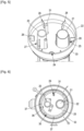
- a supporting structure 1 against which a sealed and thermally insulating tank for storing a liquefied gas is intended to be fixed.
- the supporting structure 1 is, for example, formed by the double hull of a ship.
- the supporting structure 1 has a generally polyhedral shape. It has two front and rear supporting walls 2, here octagonal in shape, of which only the rear supporting wall 2 is shown on the Figure 1 .
- the front and rear walls 2 are, for example, cofferdam walls of the ship which extend transversely to the longitudinal direction of the ship.
- the supporting structure 1 also comprises an upper supporting wall 3, a lower supporting wall 4 and side supporting walls 5, 6, 7, 8, 9, 10.
- the sealed and thermally insulating tank for storing liquefied gas comprises a plurality of tank walls which are each anchored against one of the load-bearing walls 2, 3, 5, 6, 7, 8, 9, 10 of the load-bearing structure 1 and which thus define an internal space intended to contain the liquefied gas.
- each wall of the tank successively has, from the outside to the inside, along the thickness direction of the wall, a secondary thermally insulating barrier 12 comprising insulating elements 13 fixed to the supporting structure 1, a secondary sealing membrane 14 anchored to the insulating elements 13 of the secondary thermally insulating barrier 12, a primary thermally insulating barrier 15 comprising insulating elements 16 fixed to the insulating elements 13 of the secondary thermally insulating barrier 12 or to the supporting structure 1 and resting against the secondary sealing membrane 14 and a primary sealing membrane 17 anchored to the insulating elements 16 of the primary thermally insulating barrier 15 and intended to be in contact with the liquefied gas contained in the tank.
- such membrane tanks are described in particular in the applications for patent WO14057221 , FR2691520 And FR2877638 respectively targeting the Mark V ® , Mark III ® and NO96 ® products developed by the applicant.
- the liquefied gas intended to be stored in the tank may in particular be liquefied natural gas (LNG), i.e. a gas mixture comprising mainly methane and one or more other hydrocarbons, ethane, or liquefied petroleum gas (LPG), i.e. a mixture of hydrocarbons from oil refining comprising mainly propane and butane.
- LNG liquefied natural gas
- LPG liquefied petroleum gas
- the upper load-bearing wall 3 as well as the ceiling wall 11 of the tank are interrupted locally so as to delimit an opening 18.
- the tank also comprises a dome structure 19 which projects upwards from the upper load-bearing wall 3 around the opening 18 and which defines a passage 24 which is crossed by pipes 20, 21, 31 intended respectively for loading the tank with the liquefied gas, for unloading it or for cooling it.
- the dome structure 19 comprises a shaft 22 which extends in the thickness direction of the ceiling wall 11.
- the shaft 22 is cylindrical in shape with a circular cross-section.
- the dome structure 19 also comprises a ceiling 23 which is welded to the upper end of the shaft 22.
- the ceiling 23 is advantageously curved with a downwardly directed concavity, which allows the dome structure 19 to withstand higher pressures inside the tank.
- the lower end 33 of the shaft 22 is directed towards the internal space of the tank and is sealed welded to the primary sealing membrane 17.
- the shaft 22 and the ceiling 23 are, for example, made of stainless steel.
- the shaft 22 is fixed to the upper load-bearing wall 3, for example by means of an annular fixing device 32.
- the dome structure 19 includes a closure plate 25 which is attached to the barrel 22.
- the closure plate 25 is attached to the lower end of the barrel 22 by a plurality of gussets 26, shown in the figures 4 And 5
- the gussets 26 are regularly distributed around the closing plate 25.
- the gussets 26 are, on the one hand, welded against the internal surface of the barrel 22 and, on the other hand, welded against the upper surface of the closing plate 25.
- the gussets 26 comprise here two wings perpendicular to each other and one of which is fixed to the barrel 22 and the other to the closing plate 25.
- the closing plate 25 is arranged opposite the lower end 33 of the barrel 22 so as to cover it at least partially.
- the closing plate 25 is slightly offset downwards, relative to the lower end 33 of the barrel 22.
- the vertical distance between the plane of the closing plate 25 and that of the lower end 33 of the barrel 22 is less than 50 cm and greater than 5 cm, preferably between 10 and 25 cm.
- Such a spacing between the closing plate 25 and the lower end 33 of the barrel 22 makes it possible in particular to facilitate the operations of welding the gussets 26 to the closing plate 25.
- the closing plate 25 and its orifices 27, 28, 29 cover at least 80%, advantageously at least 90% and preferably 100% of the section of the barrel 22.
- the closing plate 25 comprises a plurality of orifices 27, 28, 29 through which the pipes 20, 21, 31 pass.
- the closing plate 25 is advantageously made of stainless steel.
- an insulating lining 30 is housed in the barrel 22 so as to fill the space inside the barrel 22.
- the insulating lining 30 is chosen from glass wool and rock wool and insulating foam, such as polyurethane foam for example.
- the insulating lining comprises insulating foam, this may consist of one or more insulating blocks or be obtained by spraying an expanding foam solution inside the barrel 22.
- the insulating gasket 30 rests against the closing plate 25.
- a grid 34 shown in the Figure 3 , is interposed between the closing plate 25 and the insulating lining 30 so as to retain the insulating lining 30 inside the barrel 22.
- the closing plate 25 ensures the support of the insulating lining 30 inside the barrel 22.
- the barrel 22 and ceiling 23 of the dome structure 19 are covered with insulating lining on their outer surface projecting from the upper load-bearing wall 3 in order to form thermal continuity with the thermal insulation of the ceiling wall 11 of the tank.
- the closing plate 25 further forms a protection which protects the dome structure 19 and more particularly the barrel 22 as well as the insulating lining 30 against the phenomena of sloshing of the liquefied gas which would be likely to damage them.
- the closing plate 25 also allows the installation near the ceiling wall 11 of the tank, of a spraying device 35, shown in the figures 3 And 6 , intended to spray liquefied gas into the internal space of the tank.
- a spraying device allows in particular the cooling of the tank, prior to loading the liquefied gas inside the tank. This cooling aims to reduce the temperature inside the tank, in particular in order to avoid excessive vaporization of the liquefied gas during loading, limit the intensity of thermal stresses in certain components housed in the tank and avoid situations likely to harm the safety of the tank and/or its integrity.
- the spraying device 35 comprises the pipe 31 which successively passes through the barrel 22 or the ceiling 23 of the dome structure 19 and the insulating lining 30 which is housed in the barrel 22.
- the pipe 31 also passes through the orifice 29 made in the closing plate 25.
- the pipe 31 joins a spray ramp 36, illustrated in the Figure 6 , which is fixed against the lower surface of the closing plate 25.
- the spray bar 36 comprises a plurality of spray nozzles 37.
- the spray nozzles 37 are oriented so as to ensure a distribution of the gas spray in the internal space of the tank.
- the spray bar 36 has an annular shape and the spray nozzles 37 are regularly distributed around the central axis of said annular shape.
- the spray bar 36 can be fixed to the internal surface of the closure plate 25 by any suitable means, such as fixing collars or fixing clips, for example.
- the pipe 20 is intended for loading liquefied gas into the tank. It passes through the drum 22 and has a bent portion extended by a vertical portion which passes through the closing plate 25. The lower end of the pipe 20 therefore opens into the internal space of the tank.
- the pipe 20 is connected outside the tank to a loading pipeline which comprises a manifold intended to be connected to a maritime or port terminal or to a bunkering vessel.
- the line 21 is intended for the discharge of liquefied gas from the tank.
- the line 21 passes through the ceiling 23 of the dome structure 19 and then passes through the closure plate 25.
- the line 21 extends over substantially the entire height of the tank up to near the bottom wall of the tank.
- the line 21 is further equipped with an unloading pump, not shown.
- the dome structure 19 may also be equipped with level sensors as well as a temperature measuring device which comprises a plurality of temperature sensors which are vertically distributed in the internal space of the tank.
- the level sensors and the temperature sensors are, for example, mounted along vertical uprights which pass through one of the openings of the closing plate 25 and which each extend along one of the pipes 20, 21, 31 and are fixed thereto.
- FIGS. 7 and 8 illustrate a dome structure according to another embodiment.
- This embodiment differs from that described above in relation to the figures 3 to 6 , in particular in that the installation comprises a pipe 38 for discharging gas in the vapor phase, in that the dome structure 19 comprises a second closure plate 39 and in that the closure plate 25 as well as the second closure plate 39 are not fixed on the barrel 22 of the dome structure 19 but directly on the pipe 38.
- a pipe 38 makes it possible to evacuate the gas in the vapor phase from the internal space of the tank in order to bring it for example to the propulsion system of a ship, a reliquefaction unit or a burner.
- the closure plate 25 has an opening through which the pipe 38 passes. Furthermore, the closure plate 25 is fixed to the pipe 38 by means of gussets 40 which have an edge welded to the pipe 38 and an edge which is welded against the upper surface of the closure plate 25. In the embodiment shown, the closure plate 25 is fixed to a lower attached portion of the pipe 38 which is fixed to the rest of the pipe 38, for example by means of flanges equipped with bolts.
- the second closing plate 39 is arranged parallel to the closing plate 25, below the latter and sheet metal plates 41 are arranged between the closing plate 25 and the second closing plate 39 and welded thereto.
- the sheet metal plates 41 thus perform the function of spacer maintaining the spacing between the two closing plates 25 and 39 and the function of stiffener reinforcing the rigidity of the closing plates 25 and 39.
- the pipe 38 does not pass through the second closure plate 39 but the latter has an opening allowing the passage of gas in the vapor phase so as to allow the gas in the vapor phase stored in the internal space of the tank to reach the pipe 38.
- FIG. 9 illustrates a dome structure according to yet another embodiment.
- the barrel 22 and ceiling 23 of the dome structure 19 are covered with an insulating lining 42 on their outer surface projecting from the upper load-bearing wall 3 in order to form a thermal continuity with the thermal insulation of the ceiling wall 11 of the tank.
- the dome structure 19 comprises a gas supply pipe 43 which opens into the interior of the barrel 22 as well as a pipe 44 which passes through an opening made in the closing plate 25 and has a lower end which opens into the internal space of the tank, for example near its bottom wall.
- the pipes 43 and 44 are, for example, likely to be used during operations of putting the tank into operation or maintenance, in particular for its reheating, its inerting or its aeration.
- an inert gas when inerting the tank, an inert gas is injected into the internal space of the tank via the gas supply pipe 43.
- the inert gas thus pushes the gas making up the initial atmosphere of the tank towards the bottom of the tank, like a piston, or it is sucked in via the pipe 44.
- the insulating lining 42 it is more advantageous for the insulating lining 42 to be arranged outside and not inside the barrel 22 in order to limit pressure losses.
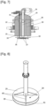
- a cutaway view of an LNG carrier 70 shows a sealed and insulated tank 71 of generally prismatic shape mounted in the double hull 72 of the ship.
- the wall of the tank 71 comprises a primary sealing membrane intended to be in contact with the LNG contained in the tank, a secondary sealing membrane arranged between the primary sealing membrane and the double hull 72 of the ship, and two thermally insulating barriers arranged respectively between the primary sealing membrane and the secondary sealing membrane and between the secondary sealing membrane and the double hull 72.
- loading/unloading pipelines 73 arranged on the upper deck of the ship can be connected, by means of appropriate connectors, to a maritime or port terminal to transfer a cargo of LNG from or to the tank 71.
- FIG. 10 also represents an example of a maritime terminal comprising a loading and unloading station 75, an underwater pipeline 76 and an onshore installation 77.
- the loading and unloading station 75 is a fixed offshore installation comprising a mobile arm 74 and a tower 78 which supports the mobile arm 74.
- the mobile arm 74 carries a bundle of insulated flexible pipes 79 which can be connected to the loading/unloading pipelines 73.
- the orientable mobile arm 74 adapts to all sizes of LNG carriers.
- a connecting pipe, not shown, extends inside the tower 78.
- the loading and unloading station 75 allows the loading and unloading of the LNG carrier 70 from or to the onshore installation 77.
- the latter comprises liquefied gas storage tanks 80 and connecting pipes 81 connected by the subsea pipe 76 to the loading or unloading station 75.
- the subsea pipe 76 allows the transfer of the liquefied gas between the loading or unloading station 75 and the onshore installation 77 over a long distance, for example 5 km, which makes it possible to keep the LNG carrier 70 at a great distance from the coast during the loading and unloading operations.
- pumps on board the ship 70 and/or pumps equipping the onshore installation 77 and/or pumps equipping the loading and unloading station 75 are used.
Landscapes
- Engineering & Computer Science (AREA)
- Mechanical Engineering (AREA)
- General Engineering & Computer Science (AREA)
- Chemical & Material Sciences (AREA)
- Combustion & Propulsion (AREA)
- Ocean & Marine Engineering (AREA)
- Filling Or Discharging Of Gas Storage Vessels (AREA)
Description
- L'invention se rapporte au domaine des installations de stockage pour gaz liquéfié comprenant une cuve étanche et thermiquement isolante pour le stockage et/ou le transport d'un gaz liquéfié, telles que des cuves pour le transport de Gaz de Pétrole Liquéfié (aussi appelé GPL) présentant, par exemple, une température comprise entre -50°C et 0°C, ou pour le transport de Gaz Naturel Liquéfié (GNL) à environ -162°C à pression atmosphérique.
- Ces installations peuvent être installées à terre ou sur un ouvrage flottant. Dans le cas d'un ouvrage flottant, la cuve de l'installation peut être destinée au transport de gaz liquéfié ou à recevoir du gaz liquéfié servant de carburant pour la propulsion de l'ouvrage flottant.
- L'invention concerne plus particulièrement une installation de stockage d'un gaz liquéfié comportant une structure de dôme qui passe au travers d'une ouverture réalisée dans la paroi de plafond de la cuve.
- Le document
WO2019215414 divulgue une installation de stockage d'un gaz liquéfié comprenant une structure porteuse formée par la double coque d'un navire et une cuve étanche et thermiquement isolante qui est logée à l'intérieur de la structure porteuse. Les parois de la cuve présentent une structure multicouche comprenant successivement, de l'extérieur vers l'intérieur, une barrière thermiquement isolante secondaire, une membrane d'étanchéité secondaire, une barrière thermiquement isolante primaire et une membrane d'étanchéité primaire destinée à être en contact avec le gaz liquéfié stocké dans la cuve. La paroi supérieure de la cuve comporte, à proximité de la paroi arrière de la structure porteuse, un espace, de forme parallélépipédique rectangle, en saillie vers le haut, appelé dôme liquide. La cuve comporte une tour de chargement/déchargement qui comporte trois mâts creux qui traversent un couvercle du dôme liquide et qui définissent soit une ligne de chargement ou de déchargement permettant de charger ou de décharger du fluide vers ou depuis la cuve, soit un puits de secours permettant la descente d'une pompe de secours et d'une ligne de déchargement en cas de défaillance des autres pompes de déchargement. Un tel dôme liquide n'est pas pleinement satisfaisant. En particulier, l'intérieur du dôme liquide est susceptible d'être soumis à des pressions dynamiques dues au phénomène de « sloshing », c'est-à-dire au mouvement de la cargaison dans la cuve. En outre, l'isolation thermique est assurée par des blocs isolants fixés à l'intérieur du dôme liquide tandis que l'étanchéité du dôme liquide est assurée par une membrane d'étanchéité qui est fixée à la barrière thermiquement isolante et qui est raccordée de manière étanche à la membrane d'étanchéité primaire de la paroi supérieure de la cuve. Ainsi, la structure d'un tel dôme liquide est relativement complexe à fabriquer. - Une idée à la base de l'invention est de proposer une cuve étanche et thermiquement isolante comportant une structure de dôme qui soit protégée contre les mouvements du gaz liquéfié à l'intérieur de la cuve.
- Une autre idée à la base de l'invention est de proposer une cuve étanche et thermiquement isolante équipée d'une structure de dôme qui présente une structure simple à fabriquer.
- Selon un mode de réalisation, l'invention fournit une installation de stockage d'un gaz liquéfié comportant une structure porteuse et une cuve étanche et thermiquement isolante agencée dans la structure porteuse, ladite cuve étanche et thermiquement isolante présentant un espace interne, la structure porteuse comprenant une paroi porteuse supérieure et la cuve comprenant une paroi de plafond fixée à la paroi porteuse supérieure, la paroi de plafond comprenant, dans une direction d'épaisseur de l'extérieur vers l'intérieur de la cuve, au moins une barrière thermiquement isolante et au moins une membrane d'étanchéité supportée par la barrière thermiquement isolante et destinée à être en contact avec le gaz liquéfié contenu dans la cuve, l'installation de stockage comprenant une structure de dôme passant au travers d'une ouverture réalisée dans la paroi de plafond et dans la paroi porteuse supérieure, la structure de dôme comportant un fût qui s'étend selon la direction d'épaisseur, ledit fût comportant une extrémité inférieure qui est dirigée vers l'espace interne de la cuve et au moins une plaque de fermeture qui est positionnée en regard de l'extrémité inférieure du fût de manière à la couvrir, la plaque de fermeture comportant un moins un orifice, l'installation de stockage comportant au moins une conduite qui est destinée à conduire du gaz liquéfié, ladite conduite traversant la structure de dôme et traversant l'orifice ménagé dans la plaque de fermeture.
- Ainsi, la plaque de fermeture permet de protéger la structure de dôme contre les mouvements du gaz liquéfié à l'intérieur de la cuve.
- Selon d'autres modes de réalisation avantageux, une telle cuve étanche et thermiquement isolante peut présenter une ou plusieurs des caractéristiques suivantes.
- Selon un mode de réalisation, le fût est de forme cylindrique à section circulaire.
- Selon un mode de réalisation, le fût est fixé à la paroi porteuse supérieure.
- Selon un mode de réalisation, le fût est soudé de manière étanche à la membrane d'étanchéité de la paroi de plafond.
- Selon un mode de réalisation, la structure de dôme comporte un plafond qui est fixé, par exemple par soudage, à une extrémité supérieure du fût.
- Selon un mode de réalisation, le plafond est bombé, ce qui permet à la structure de dôme de supporter des pressions plus importantes à l'intérieur de la cuve.
- Selon un mode de réalisation, la plaque de fermeture est fixée au fût et la conduite est montée libre, en translation selon la direction d'épaisseur, à l'intérieur de l'orifice. En d'autres termes, le plaque de fermeture n'est pas fixée à la conduite mais au fût, ce qui autorise le mouvement de la conduite par rapport à la plaque de fermeture lorsqu'elle est soumise à des phénomènes de contraction thermique, notamment lors de la mise à froid ou lors du chargement de la cuve.
- Selon un mode de réalisation, la plaque de fermeture est fixée au fût par une pluralité d'éléments de fixation.
- Selon un mode de réalisation, les éléments de fixations sont des goussets qui sont chacun fixés, d'une part, à une surface interne du fût et, d'autre part, à une surface supérieure de la plaque de fermeture.
- Selon un mode de réalisation, les goussets sont soudés à la surface interne du fût et soudés à la surface supérieure de la plaque de fermeture.
- Selon un autre mode de réalisation, la plaque de fermeture est fixée à la conduite au moyen d'au moins deux goussets.
- Selon un mode de réalisation, chaque gousset comporte un bord soudé à la conduite et un bord soudé à la plaque de fermeture, par exemple à la surface supérieure de la plaque de fermeture.
- Selon un mode de réalisation, les goussets sont orientés radialement par rapport à l'axe de la conduite et sont répartis régulièrement autour de l'axe de la conduite.
- Selon un mode de réalisation, la conduite à laquelle est fixée la plaque de fermeture est centrée par rapport au fût de la structure de dôme.
- Selon un mode de réalisation, l'installation comporte deux plaques de fermeture fixées l'une à l'autre par au moins deux plaques de tôle formant entretoise maintenant l'écartement entre les deux plaques de fermeture.
- Selon un mode de réalisation, les plaques de tôle font également office de raidisseurs.
- Selon un mode de réalisation, la structure de dôme comporte une garniture isolante qui comble l'intérieur du fût et qui repose sur la plaque de fermeture. Ainsi, l'isolation de la structure de dôme est efficace et aisée à installer.
- Selon un mode de réalisation, un grillage est interposé entre la garniture isolante et la plaque de fermeture. Le grillage permet ainsi de retenir la garniture isolante dans le fût.
- Selon un mode de réalisation, la garniture isolante est choisie parmi la laine de verre la laine de roche et la mousse isolante, telle que la mousse polyuréthane .
- Selon un mode de réalisation, la garniture isolante comporte un ou plusieurs blocs de mousse. Selon un autre mode de réalisation, la garniture isolante comporte de la mousse projetée.
- Selon un autre mode de réalisation, la structure de dôme comporte une garniture isolante qui recouvre une surface extérieure du fût qui fait saillie au-delà de la paroi porteuse supérieure de la structure porteuse.
- Selon un mode de réalisation, la garniture isolante recouvre également une surface extérieure du plafond de la structure de dôme.
- Selon un mode de réalisation, la conduite est raccordée à une rampe de pulvérisation qui est fixée à la plaque de fermeture et qui comporte une ou plusieurs buses de pulvérisation. Ceci permet une installation de la rampe de pulvérisation plus simple que lorsqu'elle est fixée à la paroi supérieure de la cuve, comme dans l'état de la technique.
- Selon un mode de réalisation, la rampe de pulvérisation présente une forme annulaire.
- Selon un mode de réalisation, les buses de pulvérisation sont réparties autour d'un axe central de la forme annulaire de la rampe de pulvérisation.
- Selon un mode de réalisation la plaque de fermeture est disposée dans l'espace interne de la cuve étanche et thermiquement isolante. La plaque de fermeture se situe ainsi en-dessous de l'extrémité inférieure du fût.
- Selon un mode de réalisation, la plaque de fermeture est disposée dans l'espace interne de la cuve étanche et thermiquement isolante, à distance, de l'extrémité inférieure du fût. Ceci permet notamment de faciliter les opérations de fixation de la plaque de fermeture au fût.
- Selon un mode de réalisation, la plaque de fermeture s'étend dans un plan qui est positionné à une distance verticale du plan de l'extrémité inférieure du fût qui est inférieure à 50 cm, avantageusement supérieure à 5 cm et de préférence comprise entre 10 et 25 cm. Ainsi, une telle distance permet de faciliter les opérations de fixation de la plaque de fermeture au fût tout en positionnant la plaque de fermeture au -dessus de la limite maximale de chargement de la cuve.
- Selon un mode de réalisation, en projection dans le plan de l'extrémité inférieure du fût, la plaque de fermeture recouvre au moins 80%, et de préférence plus de 95% de la section de l'extrémité inférieure du fût.
- Selon un mode de réalisation, la plaque de fermeture comporte une pluralité d'orifices et l'installation de stockage de gaz liquéfié comporte une pluralité de conduites destinées à conduire du gaz liquéfié, chaque conduite traversant la structure de dôme et traversant l'un des orifices ménagés dans la plaque de fermeture.
- Selon un mode de réalisation, au moins l'une des conduites est destinée au déchargement de gaz liquéfie stocké dans la cuve, ladite conduite s'étendant jusqu'à proximité d'une paroi de fond de la cuve et étant équipée d'une pompe de déchargement.
- Selon un mode de réalisation au moins l'une des conduites est destinée au chargement de gaz liquéfié stocké dans la cuve.
- L'installation selon l'un des modes de réalisation précités peut être une installation de stockage terrestre, par exemple pour stocker du GNL ou être installée dans une structure flottante, côtière ou en eau profonde, notamment un navire éthanier ou méthanier, une unité flottante de stockage et de regazéification (FSRU), une unité flottante de production et de stockage déporté (FPSO) et autres. Dans le cas d'une structure flottante, la cuve de l'installation peut être destinée à recevoir du gaz naturel liquéfié servant de carburant pour la propulsion de la structure flottante.
- Selon un mode de réalisation, un navire pour le transport d'un fluide comporte une coque, telle qu'une double coque, et une installation de stockage d'un gaz liquéfié précitée, la coque du navire formant la structure porteuse.
- Selon un mode de réalisation, l'invention fournit aussi un procédé de chargement ou déchargement d'un tel navire, dans lequel on achemine un fluide à travers des canalisations isolées depuis ou vers une installation de stockage flottante ou terrestre vers ou depuis la cuve du navire.
- Selon un mode de réalisation, l'invention fournit aussi un système de transfert pour un fluide, le système comportant le navire précité, des canalisations isolées agencées de manière à relier la cuve installée dans la coque du navire à une installation de stockage flottante ou terrestre et une pompe pour entrainer un flux de fluide à travers les canalisations isolées depuis ou vers l'installation de stockage flottante ou terrestre vers ou depuis la cuve du navire.
- L'invention sera mieux comprise, et d'autres buts, détails, caractéristiques et avantages de celle-ci apparaîtront plus clairement au cours de la description suivante de plusieurs modes de réalisation particuliers de l'invention, donnés uniquement à titre illustratif et non limitatif, en référence aux dessins annexés.
- [
fig.1 ] Lafigure 1 est vue en perspective schématique d'une structure porteuse destinée à supporter une cuve étanche et thermique isolante de stockage d'un gaz liquéfié, la structure de dôme n'étant pas représentée. - [
fig.2 ] Lafigure 2 est une vue schématique de la structure multicouche des parois de la cuve. - [
fig.3 ] Lafigure 3 est une vue schématique en coupe d'une structure de dôme d'une cuve étanche et thermiquement isolante. - [
fig.4 ] Lafigure 4 est une vue en perspective de l'extrémité inférieure de la structure de dôme de lafigure 3 dans laquelle le dispositif de pulvérisation n'est pas représenté. - [
fig.5 ] Lafigure 5 est une vue en perspective, de dessus, de l'extrémité inférieure de la structure de dôme de lafigure 3 . - [
fig.6 ] Lafigure 6 est une vue de dessous de la structure de dôme de lafigure 3 . - [
fig.7 ] Lafigure 7 est une vue en coupe d'une structure de dôme d'une cuve étanche et thermiquement isolante selon un autre mode de réalisation. - [
fig.8 ] Lafigure 8 est une vue détaillée de la conduite et des plaques de fermeture de la figure . - [
fig.9 ] Lafigure 9 une vue en coupe d'une structure de dôme d'une cuve étanche et thermiquement isolante selon encore un autre mode de réalisation. - [
fig.10 ] Lafigure 10 est une représentation schématique écorchée d'un navire comportant une cuve de stockage de gaz naturel liquéfié et d'un terminal de chargement/déchargement de cette cuve. - En relation avec la
figure 1 , l'on décrit une structure porteuse 1 contre laquelle une cuve étanche et thermiquement isolante de stockage d'un gaz liquéfié est destinée à être fixée. La structure porteuse 1 est, par exemple, formée par la double coque d'un navire. La structure porteuse 1 présente une forme générale polyédrique. Elle présente deux parois porteuses avant et arrière 2, ici de forme octogonale, dont seule la paroi porteuse arrière 2 est représentée sur lafigure 1 . Les parois avant et arrière 2 sont, par exemple, des parois de cofferdam du navire qui s'étendent transversalement à la direction longitudinale du navire. La structure porteuse 1 comporte également une paroi porteuse supérieure 3, une paroi porteuse inférieure 4 et des parois porteuses latérales 5, 6, 7, 8, 9, 10. - La cuve étanche et thermiquement isolante de stockage du gaz liquéfié comporte une pluralité de parois de cuve qui sont chacune ancrées contre l'une des parois porteuses 2, 3, 5, 6, 7, 8, 9, 10 de la structure porteuse 1 et qui définissent ainsi un espace interne destiné à contenir le gaz liquéfié.
- Comme représenté sur la
figure 2 , chaque paroi de la cuve présente successivement, de l'extérieur vers l'intérieur, selon la direction d'épaisseur de la paroi, une barrière thermiquement isolante secondaire 12 comportant des éléments isolants 13 fixés à la structure porteuse 1, une membrane d'étanchéité secondaire 14 ancrée aux éléments isolants 13 de la barrière thermiquement isolante secondaire 12, une barrière thermiquement isolante primaire 15 comportant des éléments isolants 16 fixés aux éléments isolants 13 de la barrière thermiquement isolante secondaire 12 ou à la structure porteuse 1 et reposant contre la membrane d'étanchéité secondaire 14 et une membrane d'étanchéité primaire 17 ancrée aux éléments isolants 16 de la barrière thermiquement isolante primaire 15 et destinée à être en contact avec le gaz liquéfie contenu dans la cuve. A titre d'exemple, de telles cuves à membranes sont notamment décrites dans les demandes debrevet WO14057221 FR2691520 FR2877638 - Le gaz liquéfié destiné à être stocké dans la cuve peut notamment être un gaz naturel liquéfié (GNL), c'est-à-dire un mélange gazeux comportant majoritairement du méthane ainsi qu'un ou plusieurs autres hydrocarbures, de l'éthane ou un gaz de pétrole liquéfié (GPL), c'est-à-dire un mélange d'hydrocarbures issu du raffinage du pétrole comportant essentiellement du propane et du butane.
- Comme représenté sur la
figure 3 , la paroi porteuse supérieure 3 ainsi que la paroi de plafond 11 de la cuve sont interrompues localement de manière à délimiter une ouverture 18. La cuve comporte également une structure de dôme 19 qui fait saillie vers le haut depuis la paroi porteuse supérieure 3 autour de l'ouverture 18 et qui définit un passage 24 qui est traversé par des conduites 20, 21, 31 destinées respectivement au chargement de la cuve avec le gaz liquéfié, à son déchargement ou à son refroidissement. - La structure de dôme 19 comporte un fût 22 qui s'étend selon la direction d'épaisseur de la paroi de plafond 11. Le fût 22 est de forme cylindrique à section circulaire. La structure de dôme 19 comporte également un plafond 23 qui est soudé à l'extrémité supérieure du fût 22. La plafond 23 est avantageusement bombé avec une concavité dirigée vers le bas, ce qui permet à la structure de dôme 19 de résister à des pressions plus importantes à l'intérieur de la cuve. L'extrémité inférieure 33 du fût 22 est dirigée vers l'espace interne de la cuve et est soudée de manière étanche à la membrane d'étanchéité primaire 17. Le fût 22 et le plafond 23 sont, par exemple, réalisés en acier inoxydable. Le fût 22 est fixé à la paroi porteuse supérieure 3, par exemple au moyen d'un dispositif de fixation annulaire 32.
- Par ailleurs, la structure de dôme 19 comporte une plaque de fermeture 25 qui est fixée au fût 22. La plaque de fermeture 25 est fixée à l'extrémité inférieure du fût 22 par une pluralité de goussets 26, représentés sur les
figures 4 et5 . Les goussets 26 sont régulièrement répartis autour de la plaque de fermeture 25. Les goussets 26 sont, d'une part, soudés contre la surface interne du fût 22 et, d'autre part, soudés contre la surface supérieure de la plaque de fermeture 25. Les goussets 26 comportent ici deux ailes perpendiculaires l'une à l'autre et dont l'une est fixée au fût 22 et l'autre à la plaque de fermeture 25. - La plaque de fermeture 25 est disposée en regard de l'extrémité inférieure 33 du fût 22 de manière à la couvrir au moins partiellement. Dans le mode de réalisation représenté, la plaque de fermeture 25 est légèrement décalée vers le bas, par rapport à l'extrémité inférieure 33 du fût 22. A titre d'exemple, la distance verticale entre le plan de la plaque de fermeture 25 et celui de l'extrémité inférieure 33 du fût 22 est inférieure à 50 cm et supérieure à 5 cm, de préférence comprise entre 10 et 25 cm. Un tel écartement entre la plaque de fermeture 25 et l'extrémité inférieure 33 du fût 22 permet notamment de faciliter les opérations de soudage des goussets 26 à la plaque de fermeture 25.
- De manière avantageuse, en projection selon un axe vertical dans le plan de l'extrémité inférieure 33 du fut 22, la plaque de fermeture 25 et ses orifices 27, 28, 29 recouvrent au moins 80%, avantageusement au moins 90% et de préférence 100 % de la section du fût 22. La plaque de fermeture 25 comporte une pluralité d'orifices 27, 28, 29 au travers desquels passent les conduites 20, 21, 31. La plaque de fermeture 25 est avantageusement en acier inoxydable.
- Par ailleurs, dans le mode de réalisation représenté, afin d'assurer l'isolation de la structure de dôme 19, une garniture isolante 30 est logée dans le fût 22 de manière à combler l'espace à l'intérieur du fût 22. Selon un mode de réalisation, la garniture isolante 30 est choisie parmi la laine de verre et la laine de roche et la mousse isolante, tel que de la mousse polyuréthane par exemple. Lorsque la garniture isolante comporte de la mousse isolante, celle-ci peut être constituée d'un ou de plusieurs blocs isolants ou être obtenue par projection d'une solution de mousse expansive à l'intérieur du fût 22.
- La garniture isolante 30 repose contre la plaque de fermeture 25. De manière avantageuse, un grillage 34, représenté sur la
figure 3 , est interposé entre la plaque de fermeture 25 et la garniture isolante 30 de manière à retenir la garniture isolante 30 à l'intérieur du fût 22. Ainsi, la plaque de fermeture 25 assure le support de la garniture isolante 30 à l'intérieur du fût 22. - Selon un autre mode de réalisation non représenté, de manière complémentaire ou alternative à la garniture isolante 30 qui est logée dans le fût 22, le fût 22 et plafond 23 de la structure de dôme 19 sont recouverts de garniture isolante sur leur surface extérieure faisant saillie de la paroi porteuse supérieure 3 afin de former une continuité thermique avec l'isolation thermique de de la paroi de plafond 11 de la cuve.
- La plaque de fermeture 25 forme, en outre, une protection qui protège la structure de dôme 19 et plus particulièrement le fût 22 ainsi que la garniture isolante 30 contre les phénomènes de ballottement du gaz liquéfié qui seraient susceptibles de les dégrader.
- Par ailleurs, la plaque de fermeture 25 permet également l'installation à proximité de la paroi de plafond 11 de la cuve, d'un dispositif de pulvérisation 35, représenté sur les
figures 3 et6 , destiné à pulvériser du gaz liquéfié dans l'espace interne de la cuve. Un tel dispositif de pulvérisation permet notamment la mise à froid de la cuve, préalablement au chargement du gaz liquéfié à l'intérieur de la cuve. Cette mise en froid vise à réduire la température à l'intérieur de la cuve, notamment afin d'éviter une vaporisation excessive du gaz liquéfié lors du chargement, limiter l'intensité des contraintes thermiques dans certains composants logés dans la cuve et éviter des situations susceptibles de nuire à la sécurité de la cuve et/ou à son intégrité. Le dispositif de pulvérisation 35 comporte la conduite 31 qui traverse successivement le fût 22 ou le plafond 23 de la structure de dôme 19 et la garniture isolante 30 qui est logée dans le fût 22. La conduite 31 traverse également l'orifice 29 ménagé dans la plaque de fermeture 25. La conduite 31 rejoint une rampe de pulvérisation 36, illustrée sur lafigure 6 , qui est fixée contre la surface inférieure de la plaque de fermeture 25. - La rampe de pulvérisation 36 comporte une pluralité de buses de pulvérisation 37. Les buses de pulvérisation 37 sont orientées de manière à assurer une répartition de la pulvérisation du gaz dans l'espace interne de la cuve. Selon la variante de réalisation représentée, la rampe de pulvérisation 36 présente une forme annulaire et les buses de pulvérisation 37 sont régulièrement réparties autour de l'axe central de ladite forme annulaire. La rampe de pulvérisation 36 peut être fixée à la surface interne de la plaque de fermeture 25 par tout moyen approprié, tels que des colliers de fixation ou des clips de fixation, par exemple.
- La conduite 20 est destinée au chargement de gaz liquéfié dans la cuve. Elle passe au travers du fût 22 et présente une portion coudée prolongée par une portion verticale qui passe au travers de la plaque de fermeture 25. L'extrémité inférieure de la conduite 20 débouche donc dans l'espace interne de la cuve. En outre, la conduite 20 est raccordée à l'extérieur de la cuve à une canalisation de chargement qui comporte un manifold destiné à être raccordé à un terminal maritime ou portuaire ou à un navire souteur.
- La conduite 21 est destinée au déchargement de gaz liquéfié depuis la cuve. Dans le mode de réalisation représenté, la conduite 21 passe au travers du plafond 23 de la structure de dôme 19 puis traverse la plaque de fermeture 25. La conduite 21 s'étend sur sensiblement toute la hauteur de la cuve jusqu'à proximité de la paroi de fond de la cuve. La conduite 21 est en outre équipée d'une pompe de déchargement, non représentée.
- La structure de dôme 19 peut également être équipée de capteurs de niveau ainsi que d'un dispositif de mesure de températures qui comprend une pluralité de capteurs de températures qui sont verticalement réparties dans l'espace interne de la cuve. Les capteurs de niveau et les capteurs de températures sont, par exemple, montés le long de montants verticaux qui passent au travers d'une des ouvertures de la plaque de fermeture 25 et qui s'étendent chacun le long de l'une des conduites 20, 21, 31 et sont fixés à celle-ci.
- Les
figures 7 et 8 illustrent une structure de dôme selon un autre mode de réalisation. Ce mode de réalisation diffère de celui décrit ci-dessus en relation avec lesfigures 3 à 6 , notamment en ce que l'installation comporte une conduite 38 pour évacuer du gaz en phase vapeur, en ce que la structure de dôme 19 comporte une seconde plaque de fermeture 39 et en ce que la plaque de fermeture 25 ainsi que la seconde plaque de fermeture 39 ne sont pas fixés sur le fût 22 de la structure de dôme 19 mais directement sur la conduite 38 . Une telle conduite 38 permet d'évacuer le gaz en phase vapeur de l'espace interne de la cuve afin de l'amener par exemple vers le système de propulsion d'un navire, une unité de reliquéfaction ou un brûleur. - Comme représenté sur la
figure 8 , la plaque de fermeture 25 présente une ouverture au travers de laquelle passe la conduite 38. Par ailleurs, la plaque de fermeture 25 est fixée à la conduite 38 au moyen de goussets 40 qui comportent un bord soudé à la conduite 38 et un bord qui est soudé contre la surface supérieure de la plaque de fermeture 25. Dans le mode de réalisation représenté, la plaque de fermeture 25 est fixée à une portion inférieure rapportée de la conduite 38 qui est fixée au reste de la conduite 38, par exemple au moyen de brides équipées de boulons. - Par ailleurs, la seconde plaque de fermeture 39 est disposée parallèlement à la plaque de fermeture 25, en dessous de celle-ci et des plaques de tôle 41 sont disposées entre la plaque de fermeture 25 et la seconde plaque de fermeture 39 et soudées à celles-ci. Les plaques de tôle 41 assurent ainsi la fonction d'entretoise maintenant l'écartement entre les deux plaques de fermeture 25 et 39 et la fonction de raidisseur renforçant la rigidité des plaques de fermetures 25 et 39. Dans le mode de réalisation représenté, la conduite 38 ne traverse pas la seconde plaque de fermeture 39 mais celle-ci présente une ouverture permettant le passage de gaz en phase vapeur de manière à permettre au gaz en phase vapeur stocké dans l'espace interne de la cuve de rejoindre la conduite38.
- La
figure 9 illustre une structure de dôme selon encore un autre mode de réalisation. Dans ce mode de réalisation, le fût 22 et plafond 23 de la structure de dôme 19 sont recouverts d'une garniture isolante 42 sur leur surface extérieure faisant saillie de la paroi porteuse supérieure 3 afin de former une continuité thermique avec l'isolation thermique de de la paroi de plafond 11 de la cuve. Par ailleurs, la structure de dôme 19 comporte, une conduite d'alimentation en gaz 43 qui débouche à l'intérieur du fût 22 ainsi qu'une conduite 44 qui passe au travers d'une ouverture ménagée dans la plaque de fermeture 25 et présente une extrémité inférieure qui débouche dans l'espace interne de la cuve, par exemple à proximité de sa paroi de fond. Les conduites 43 et 44 sont, par exemple, susceptibles d'être utilisés lors des opérations de mise en opération ou de maintenance de la cuve, notamment pour son réchauffage, son inertage ou son aération. Ainsi, à titre d'exemple, lors de l'inertage de la cuve, un gaz inerte est injecté dans l'espace interne de la cuve par la conduite d'alimentation en gaz 43. Le gaz inerte repousse ainsi le gaz composant l'atmosphère initial de la cuve vers le fond de la cuve, à la manière d'un piston, ou il est aspiré par l'intermédiaire de la conduite 44. On notera ainsi que pour un tel mode de réalisation dans lequel du gaz est injecté à l'intérieur de la structure de dôme 19, il est plus avantageux que la garniture isolante 42 soit disposé à l'extérieur et non à l'intérieur du fût 22 afin de limiter les pertes de charge. - En référence à la
figure 10 , une vue écorchée d'un navire méthanier 70 montre une cuve étanche et isolée 71 de forme générale prismatique montée dans la double coque 72 du navire. La paroi de la cuve 71 comporte une membrane d'étanchéité primaire destinée à être en contact avec le GNL contenu dans la cuve, une membrane d'étanchéité secondaire agencée entre la membrane d'étanchéité primaire et la double coque 72 du navire, et deux barrières thermiquement isolantes agencées respectivement entre la membrane d'étanchéité primaire et la membrane d'étanchéité secondaire et entre la membrane d'étanchéité secondaire et la double coque 72. - De manière connue en soi, des canalisations de chargement/déchargement 73 disposées sur le pont supérieur du navire peuvent être raccordées, au moyen de connecteurs appropriées, à un terminal maritime ou portuaire pour transférer une cargaison de GNL depuis ou vers la cuve 71.
- La
figure 10 représente également un exemple de terminal maritime comportant un poste de chargement et de déchargement 75, une conduite sous-marine 76 et une installation à terre 77. Le poste de chargement et de déchargement 75 est une installation fixe off-shore comportant un bras mobile 74 et une tour 78 qui supporte le bras mobile 74. Le bras mobile 74 porte un faisceau de tuyaux flexibles isolés 79 pouvant se connecter aux canalisations de chargement/déchargement 73. Le bras mobile 74 orientable s'adapte à tous les gabarits de méthaniers. Une conduite de liaison non représentée s'étend à l'intérieur de la tour 78. Le poste de chargement et de déchargement 75 permet le chargement et le déchargement du méthanier 70 depuis ou vers l'installation à terre 77. Celle-ci comporte des cuves de stockage de gaz liquéfié 80 et des conduites de liaison 81 reliées par la conduite sous-marine 76 au poste de chargement ou de déchargement 75. La conduite sous-marine 76 permet le transfert du gaz liquéfié entre le poste de chargement ou de déchargement 75 et l'installation à terre 77 sur une grande distance, par exemple 5 km, ce qui permet de garder le navire méthanier 70 à grande distance de la côte pendant les opérations de chargement et de déchargement. - Pour engendrer la pression nécessaire au transfert du gaz liquéfié, on met en oeuvre des pompes embarquées dans le navire 70 et/ou des pompes équipant l'installation à terre 77 et/ou des pompes équipant le poste de chargement et de déchargement 75.
- Bien que l'invention ait été décrite en liaison avec plusieurs modes de réalisation particuliers, il est bien évident qu'elle n'y est nullement limitée et qu'elle comprend tous les équivalents techniques des moyens décrits ainsi que leurs combinaisons si celles-ci entrent dans le cadre de l'invention, telle que définie par les revendications.
- L'usage du verbe « comporter », « comprendre » ou « inclure » et de ses formes conjuguées n'exclut pas la présence d'autres éléments ou d'autres étapes que ceux énoncés dans une revendication.
- Dans les revendications, tout signe de référence entre parenthèses ne saurait être interprété comme une limitation de la revendication.
Claims (20)
- Installation de stockage d'un gaz liquéfié comportant une structure porteuse (1) et une cuve étanche et thermiquement isolante agencée dans la structure porteuse (1), ladite cuve étanche et thermiquement isolante présentant un espace interne, la structure porteuse (1) comprenant une paroi porteuse supérieure (3) et la cuve comprenant une paroi de plafond (11) fixée à la paroi porteuse supérieure (3), la paroi de plafond (11) comprenant, dans une direction d'épaisseur de l'extérieur vers l'intérieur de la cuve, au moins une barrière thermiquement isolante (12, 15) et au moins une membrane d'étanchéité (17) supportée par la barrière thermiquement isolante (12, 15) et destinée à être en contact avec le gaz liquéfié contenu dans la cuve,l'installation de stockage comprenant une structure de dôme (19) passant au travers d'une ouverture (18) réalisée dans la paroi de plafond (11) et dans la paroi porteuse supérieure (3), la structure de dôme (19) comportant un fût (22) qui s'étend selon la direction d'épaisseur, ledit fût (22) comportant une extrémité inférieure (33) qui est dirigée vers l'espace interne de la cuve et au moins une plaque de fermeture (25, 39) qui est positionnée en regard de l'extrémité inférieure (33) du fût (22) de manière à la couvrir, la plaque de fermeture (25) comportant un moins un orifice (27, 28, 29),l'installation de stockage comportant au moins une conduite (20, 21, 31, 38, 44) qui est destinée à conduire du gaz liquéfié, ladite conduite (20, 21, 31) traversant la structure de dôme (19) et traversant l'orifice (27, 28, 29) ménagé dans la plaque de fermeture (25).
- Installation de stockage d'un gaz liquéfié selon la revendication 1, dans laquelle la plaque de fermeture (25) est fixée au fût (22) et la conduite (20, 21, 31) est montée libre, en translation selon la direction d'épaisseur, à l'intérieur de l'orifice (27, 28, 29).
- Installation de stockage d'un gaz liquéfié selon la revendication 2, dans laquelle la plaque de fermeture (25) est fixée au fût (22) par une pluralité d'éléments de fixation (26).
- Installation de stockage d'un gaz liquéfié selon la revendication 3, dans laquelle les éléments de fixation sont des goussets (26) qui sont chacun fixés, d'une part, à une surface interne du fût (22) et, d'autre part, à une surface supérieure de la plaque de fermeture (25).
- Installation de stockage d'un gaz liquéfié selon la revendication 1, dans laquelle la plaque de fermeture (25) est fixée à la conduite (38) au moyen d'au moins deux goussets (40).
- Installation de stockage d'un gaz liquéfié selon l'une quelconque des revendications 1 à 5, comportant deux plaques de fermeture (25, 39) fixées l'une à l'autre par au moins deux plaques de tôle (41) formant entretoise maintenant l'écartement entre les deux plaques de fermeture (25, 39).
- Installation de stockage d'un gaz liquéfié selon l'une quelconque des revendications 1 à 6, dans laquelle la structure de dôme (19) comporte une garniture isolante (30) qui comble l'intérieur du fût (22) et qui repose sur la plaque de fermeture (25).
- Installation de stockage d'un gaz liquéfié selon la revendication 7, dans laquelle un grillage (34) est interposé entre la garniture isolante (30) et la plaque de fermeture (25).
- Installation de stockage d'un gaz liquéfié selon la revendication 7 ou 8, dans laquelle la garniture isolante (30) est choisie parmi la laine de verre, la laine de roche et la mousse isolante.
- Installation de stockage d'un gaz liquéfié selon l'une quelconque des revendications 1 à 6, dans laquelle la structure de dôme (19) comporte une garniture isolante (42) qui recouvre une surface extérieure (30) du fût (22) qui fait saillie au-delà de la paroi porteuse supérieure (3) de la structure porteuse (1).
- Installation de stockage d'un gaz liquéfié selon l'une quelconque des revendications 1 à 10, dans laquelle la conduite est raccordée à une rampe de pulvérisation (36) qui est fixée à la plaque de fermeture (25) et qui comporte une ou plusieurs buses de pulvérisation (37).
- Installation de stockage d'un gaz liquéfié selon la revendication 11, dans laquelle la rampe de pulvérisation (36) présente une forme annulaire.
- Installation de stockage d'un gaz liquéfié selon l'une quelconque des revendications 1 à 12, dans laquelle la plaque de fermeture (25) est disposée dans l'espace interne de la cuve étanche et thermiquement isolante, à distance, de l'extrémité inférieure (33) du fût (22).
- Installation de stockage d'un gaz liquéfié selon l'une quelconque des revendications 1 à 13, dans laquelle, en projection verticale dans le plan de l'extrémité inférieure (33) du fût (22), la plaque de fermeture (25) recouvre au moins 80% de la section de l'extrémité inférieure (33) du fût (22).
- Installation de stockage d'un gaz liquéfié selon l'une quelconque des revendications 1 à 14, dans laquelle la plaque de fermeture (25) comporte une pluralité d'orifices (27, 28, 29) et l'installation de stockage de gaz liquéfié comporte une pluralité de conduites (20, 21, 31) destinées à conduire du gaz liquéfié, chaque conduite (20, 21, 31) traversant la structure de dôme (19) et traversant l'un des orifices (27, 28, 29) ménagés dans la plaque de fermeture (25).
- Installation de stockage d'un gaz liquéfié selon la revendication 15, dans laquelle au moins l'une des conduites (21) est destinée au déchargement de gaz liquéfie stocké dans la cuve, ladite conduite (21) s'étendant jusqu'à proximité d'une paroi de fond de la cuve et étant équipée d'une pompe de déchargement.
- Installation de stockage d'un gaz liquéfié selon la revendication 15 ou 16, dans laquelle au moins l'une des conduites (20) est destinée au chargement de gaz liquéfié stocké dans la cuve.
- Navire (70) pour le transport d'un fluide, le navire comportant une coque (72) et une installation de stockage d'un gaz liquéfié selon l'une quelconque des revendications 1 à 17, la coque du navire (70) formant la structure porteuse.
- Système de transfert pour un gaz liquéfié, le système comportant un navire (70) selon la revendication 18, des canalisations isolées (73, 79, 76, 81) agencées de manière à relier la cuve (71) installée dans la coque du navire à une installation de stockage flottante ou terrestre (77) et une pompe pour entrainer un fluide à travers les canalisations isolées depuis ou vers l'installation de stockage flottante ou terrestre vers ou depuis la cuve du navire.
- Procédé de chargement ou déchargement d'un navire (70) selon la revendication 18, dans lequel on achemine un fluide à travers des canalisations isolées (73, 79, 76, 81) depuis ou vers une installation de stockage flottante ou terrestre (77) vers ou depuis la cuve du navire (71).
Applications Claiming Priority (1)
| Application Number | Priority Date | Filing Date | Title |
|---|---|---|---|
| FR2113916A FR3130931B1 (fr) | 2021-12-17 | 2021-12-17 | Installation de stockage d’un gaz liquéfié comportant une cuve et une structure de dôme |
Publications (3)
| Publication Number | Publication Date |
|---|---|
| EP4198375A1 EP4198375A1 (fr) | 2023-06-21 |
| EP4198375C0 EP4198375C0 (fr) | 2025-05-21 |
| EP4198375B1 true EP4198375B1 (fr) | 2025-05-21 |
Family
ID=80736039
Family Applications (1)
| Application Number | Title | Priority Date | Filing Date |
|---|---|---|---|
| EP22211708.7A Active EP4198375B1 (fr) | 2021-12-17 | 2022-12-06 | Installation de stockage d'un gaz liquefie comportant une cuve et une structure de dome |
Country Status (5)
| Country | Link |
|---|---|
| EP (1) | EP4198375B1 (fr) |
| JP (1) | JP2023090674A (fr) |
| KR (1) | KR20230093168A (fr) |
| CN (1) | CN116265802A (fr) |
| FR (1) | FR3130931B1 (fr) |
Families Citing this family (1)
| Publication number | Priority date | Publication date | Assignee | Title |
|---|---|---|---|---|
| CN117485490A (zh) * | 2023-11-17 | 2024-02-02 | 大连船舶重工集团有限公司 | 一种新型的壳体连续c型储舱液穹 |
Family Cites Families (7)
| Publication number | Priority date | Publication date | Assignee | Title |
|---|---|---|---|---|
| FR2691520B1 (fr) | 1992-05-20 | 1994-09-02 | Technigaz Ste Nle | Structure préfabriquée de formation de parois étanches et thermiquement isolantes pour enceinte de confinement d'un fluide à très basse température. |
| FR2877638B1 (fr) | 2004-11-10 | 2007-01-19 | Gaz Transp Et Technigaz Soc Pa | Cuve etanche et thermiquement isolee a elements calorifuges resistants a la compression |
| FR2996520B1 (fr) | 2012-10-09 | 2014-10-24 | Gaztransp Et Technigaz | Cuve etanche et thermiquement isolante comportant une membrane metalique ondulee selon des plis orthogonaux |
| FR3078135B1 (fr) * | 2018-02-20 | 2021-01-15 | Gaztransport Et Technigaz | Installation de stockage et de transport d'un fluide cryogenique embarquee sur un navire |
| FR3081041B1 (fr) | 2018-05-11 | 2021-03-19 | Gaztransport Et Technigaz | Procede d'assemblage d'une cuve etanche et thermiquement isolante |
| FR3109978B1 (fr) * | 2020-05-11 | 2022-04-08 | Gaztransport Et Technigaz | Dôme liquide d’une cuve de stockage pour gaz liquéfié comportant une ouverture munie d’une trappe additionnelle |
| FR3110669B1 (fr) * | 2020-05-20 | 2024-08-02 | Gaztransport Et Technigaz | Installation de stockage pour gaz liquéfié |
-
2021
- 2021-12-17 FR FR2113916A patent/FR3130931B1/fr active Active
-
2022
- 2022-12-06 EP EP22211708.7A patent/EP4198375B1/fr active Active
- 2022-12-12 JP JP2022197854A patent/JP2023090674A/ja active Pending
- 2022-12-14 CN CN202211609353.2A patent/CN116265802A/zh active Pending
- 2022-12-14 KR KR1020220175178A patent/KR20230093168A/ko active Pending
Also Published As
| Publication number | Publication date |
|---|---|
| KR20230093168A (ko) | 2023-06-27 |
| EP4198375A1 (fr) | 2023-06-21 |
| FR3130931B1 (fr) | 2023-12-22 |
| FR3130931A1 (fr) | 2023-06-23 |
| EP4198375C0 (fr) | 2025-05-21 |
| CN116265802A (zh) | 2023-06-20 |
| JP2023090674A (ja) | 2023-06-29 |
Similar Documents
| Publication | Publication Date | Title |
|---|---|---|
| EP3250849B1 (fr) | Installation de stockage et de transport d'un fluide cryogénique embarquée sur un navire | |
| EP3472509B1 (fr) | Structure de dome gaz pour une cuve etanche et thermiquement isolante | |
| EP3948060B1 (fr) | Cuve étanche et thermiquement isolante | |
| WO2019155154A1 (fr) | Installation pour le stockage et le transport d'un gaz liquefie | |
| WO2023001678A1 (fr) | Installation de stockage pour gaz liquéfié | |
| WO2017174938A1 (fr) | Cuve étanche et thermiquement isolante | |
| WO2022106692A1 (fr) | Dôme liquide d'une cuve de stockage pour gaz liquéfié | |
| WO2021228751A1 (fr) | Dôme liquide d'une cuve de stockage pour gaz liquéfié comportant une ouverture munie d'une trappe additionnelle | |
| EP4198375B1 (fr) | Installation de stockage d'un gaz liquefie comportant une cuve et une structure de dome | |
| EP4083494A1 (fr) | Installation de stockage pour gaz liquefie | |
| WO2023025501A1 (fr) | Installation de stockage pour gaz liquéfié | |
| WO2023036769A1 (fr) | Installation de stockage pour gaz liquéfié | |
| WO2021140218A1 (fr) | Installation de stockage pour gaz liquéfié | |
| WO2021053055A1 (fr) | Cuve etanche et thermiquement isolante | |
| FR3111410A1 (fr) | Dôme liquide d’une cuve de stockage pour gaz liquéfié | |
| WO2023227379A1 (fr) | Structure de dôme pour une cuve étanche et thermiquement isolante | |
| WO2021233712A1 (fr) | Installation de stockage pour gaz liquéfié | |
| WO2019162594A2 (fr) | Installation de stockage et de transport d'un fluide cryogenique embarquee sur un navire | |
| FR3118796A1 (fr) | Installation de stockage pour gaz liquéfié | |
| FR3149949A1 (fr) | Installation de stockage d’un gaz liquéfié comportant une structure de dôme supportant une rampe de pulvérisation | |
| FR3138903A1 (fr) | Procédé d’installation d’une rampe de pulvérisation sur une cuve | |
| WO2025045663A1 (fr) | Cuve étanche et thermiquement isolante | |
| FR3148283A1 (fr) | Cuve étanche et thermiquement isolante comprenant une gaine rigide creuse pour le passage de câbles électriques | |
| FR3151073A1 (fr) | Installation de stockage d’un gaz liquéfié comportant une structure de dôme | |
| FR3145397A1 (fr) | Installation de stockage de gaz liquéfié |
Legal Events
| Date | Code | Title | Description |
|---|---|---|---|
| PUAI | Public reference made under article 153(3) epc to a published international application that has entered the european phase |
Free format text: ORIGINAL CODE: 0009012 |
|
| STAA | Information on the status of an ep patent application or granted ep patent |
Free format text: STATUS: THE APPLICATION HAS BEEN PUBLISHED |
|
| AK | Designated contracting states |
Kind code of ref document: A1 Designated state(s): AL AT BE BG CH CY CZ DE DK EE ES FI FR GB GR HR HU IE IS IT LI LT LU LV MC ME MK MT NL NO PL PT RO RS SE SI SK SM TR |
|
| STAA | Information on the status of an ep patent application or granted ep patent |
Free format text: STATUS: REQUEST FOR EXAMINATION WAS MADE |
|
| 17P | Request for examination filed |
Effective date: 20231114 |
|
| RBV | Designated contracting states (corrected) |
Designated state(s): AL AT BE BG CH CY CZ DE DK EE ES FI FR GB GR HR HU IE IS IT LI LT LU LV MC ME MK MT NL NO PL PT RO RS SE SI SK SM TR |
|
| GRAP | Despatch of communication of intention to grant a patent |
Free format text: ORIGINAL CODE: EPIDOSNIGR1 |
|
| STAA | Information on the status of an ep patent application or granted ep patent |
Free format text: STATUS: GRANT OF PATENT IS INTENDED |
|
| INTG | Intention to grant announced |
Effective date: 20250113 |
|
| GRAS | Grant fee paid |
Free format text: ORIGINAL CODE: EPIDOSNIGR3 |
|
| GRAA | (expected) grant |
Free format text: ORIGINAL CODE: 0009210 |
|
| STAA | Information on the status of an ep patent application or granted ep patent |
Free format text: STATUS: THE PATENT HAS BEEN GRANTED |
|
| AK | Designated contracting states |
Kind code of ref document: B1 Designated state(s): AL AT BE BG CH CY CZ DE DK EE ES FI FR GB GR HR HU IE IS IT LI LT LU LV MC ME MK MT NL NO PL PT RO RS SE SI SK SM TR |
|
| REG | Reference to a national code |
Ref country code: GB Ref legal event code: FG4D Free format text: NOT ENGLISH |
|
| REG | Reference to a national code |
Ref country code: CH Ref legal event code: EP |
|
| REG | Reference to a national code |
Ref country code: DE Ref legal event code: R096 Ref document number: 602022014922 Country of ref document: DE |
|
| REG | Reference to a national code |
Ref country code: IE Ref legal event code: FG4D Free format text: LANGUAGE OF EP DOCUMENT: FRENCH |
|
| U01 | Request for unitary effect filed |
Effective date: 20250612 |