EP4198301B1 - Hauptwellenbefestigung - Google Patents
Hauptwellenbefestigung Download PDFInfo
- Publication number
- EP4198301B1 EP4198301B1 EP22211827.5A EP22211827A EP4198301B1 EP 4198301 B1 EP4198301 B1 EP 4198301B1 EP 22211827 A EP22211827 A EP 22211827A EP 4198301 B1 EP4198301 B1 EP 4198301B1
- Authority
- EP
- European Patent Office
- Prior art keywords
- main shaft
- fixture
- wind turbine
- shaft fixture
- nacelle
- Prior art date
- Legal status (The legal status is an assumption and is not a legal conclusion. Google has not performed a legal analysis and makes no representation as to the accuracy of the status listed.)
- Active
Links
Images


Classifications
-
- F—MECHANICAL ENGINEERING; LIGHTING; HEATING; WEAPONS; BLASTING
- F03—MACHINES OR ENGINES FOR LIQUIDS; WIND, SPRING, OR WEIGHT MOTORS; PRODUCING MECHANICAL POWER OR A REACTIVE PROPULSIVE THRUST, NOT OTHERWISE PROVIDED FOR
- F03D—WIND MOTORS
- F03D80/00—Details, components or accessories not provided for in groups F03D1/00 - F03D17/00
- F03D80/50—Maintenance or repair
-
- B—PERFORMING OPERATIONS; TRANSPORTING
- B23—MACHINE TOOLS; METAL-WORKING NOT OTHERWISE PROVIDED FOR
- B23B—TURNING; BORING
- B23B31/00—Chucks; Expansion mandrels; Adaptations thereof for remote control
- B23B31/02—Chucks
- B23B31/10—Chucks characterised by the retaining or gripping devices or their immediate operating means
- B23B31/101—Chucks with separately-acting jaws movable radially
-
- F—MECHANICAL ENGINEERING; LIGHTING; HEATING; WEAPONS; BLASTING
- F03—MACHINES OR ENGINES FOR LIQUIDS; WIND, SPRING, OR WEIGHT MOTORS; PRODUCING MECHANICAL POWER OR A REACTIVE PROPULSIVE THRUST, NOT OTHERWISE PROVIDED FOR
- F03D—WIND MOTORS
- F03D13/00—Assembly, mounting or commissioning of wind motors; Arrangements specially adapted for transporting wind motor components
- F03D13/10—Assembly of wind motors; Arrangements for erecting wind motors
- F03D13/139—Assembling or erecting wind motors by using lifting means
-
- B—PERFORMING OPERATIONS; TRANSPORTING
- B23—MACHINE TOOLS; METAL-WORKING NOT OTHERWISE PROVIDED FOR
- B23B—TURNING; BORING
- B23B31/00—Chucks; Expansion mandrels; Adaptations thereof for remote control
- B23B31/02—Chucks
- B23B31/10—Chucks characterised by the retaining or gripping devices or their immediate operating means
- B23B31/12—Chucks with simultaneously-acting jaws, whether or not also individually adjustable
- B23B31/16—Chucks with simultaneously-acting jaws, whether or not also individually adjustable moving radially
-
- F—MECHANICAL ENGINEERING; LIGHTING; HEATING; WEAPONS; BLASTING
- F03—MACHINES OR ENGINES FOR LIQUIDS; WIND, SPRING, OR WEIGHT MOTORS; PRODUCING MECHANICAL POWER OR A REACTIVE PROPULSIVE THRUST, NOT OTHERWISE PROVIDED FOR
- F03D—WIND MOTORS
- F03D80/00—Details, components or accessories not provided for in groups F03D1/00 - F03D17/00
- F03D80/70—Bearing or lubricating arrangements
-
- F—MECHANICAL ENGINEERING; LIGHTING; HEATING; WEAPONS; BLASTING
- F05—INDEXING SCHEMES RELATING TO ENGINES OR PUMPS IN VARIOUS SUBCLASSES OF CLASSES F01-F04
- F05B—INDEXING SCHEME RELATING TO WIND, SPRING, WEIGHT, INERTIA OR LIKE MOTORS, TO MACHINES OR ENGINES FOR LIQUIDS COVERED BY SUBCLASSES F03B, F03D AND F03G
- F05B2230/00—Manufacture
- F05B2230/60—Assembly methods
- F05B2230/61—Assembly methods using auxiliary equipment for lifting or holding
-
- F—MECHANICAL ENGINEERING; LIGHTING; HEATING; WEAPONS; BLASTING
- F05—INDEXING SCHEMES RELATING TO ENGINES OR PUMPS IN VARIOUS SUBCLASSES OF CLASSES F01-F04
- F05B—INDEXING SCHEME RELATING TO WIND, SPRING, WEIGHT, INERTIA OR LIKE MOTORS, TO MACHINES OR ENGINES FOR LIQUIDS COVERED BY SUBCLASSES F03B, F03D AND F03G
- F05B2230/00—Manufacture
- F05B2230/80—Repairing, retrofitting or upgrading methods
-
- F—MECHANICAL ENGINEERING; LIGHTING; HEATING; WEAPONS; BLASTING
- F05—INDEXING SCHEMES RELATING TO ENGINES OR PUMPS IN VARIOUS SUBCLASSES OF CLASSES F01-F04
- F05B—INDEXING SCHEME RELATING TO WIND, SPRING, WEIGHT, INERTIA OR LIKE MOTORS, TO MACHINES OR ENGINES FOR LIQUIDS COVERED BY SUBCLASSES F03B, F03D AND F03G
- F05B2240/00—Components
- F05B2240/60—Shafts
-
- F—MECHANICAL ENGINEERING; LIGHTING; HEATING; WEAPONS; BLASTING
- F05—INDEXING SCHEMES RELATING TO ENGINES OR PUMPS IN VARIOUS SUBCLASSES OF CLASSES F01-F04
- F05B—INDEXING SCHEME RELATING TO WIND, SPRING, WEIGHT, INERTIA OR LIKE MOTORS, TO MACHINES OR ENGINES FOR LIQUIDS COVERED BY SUBCLASSES F03B, F03D AND F03G
- F05B2260/00—Function
- F05B2260/30—Retaining components in desired mutual position
- F05B2260/31—Locking rotor in position
-
- F—MECHANICAL ENGINEERING; LIGHTING; HEATING; WEAPONS; BLASTING
- F16—ENGINEERING ELEMENTS AND UNITS; GENERAL MEASURES FOR PRODUCING AND MAINTAINING EFFECTIVE FUNCTIONING OF MACHINES OR INSTALLATIONS; THERMAL INSULATION IN GENERAL
- F16C—SHAFTS; FLEXIBLE SHAFTS; ELEMENTS OR CRANKSHAFT MECHANISMS; ROTARY BODIES OTHER THAN GEARING ELEMENTS; BEARINGS
- F16C2360/00—Engines or pumps
- F16C2360/31—Wind motors
-
- F—MECHANICAL ENGINEERING; LIGHTING; HEATING; WEAPONS; BLASTING
- F16—ENGINEERING ELEMENTS AND UNITS; GENERAL MEASURES FOR PRODUCING AND MAINTAINING EFFECTIVE FUNCTIONING OF MACHINES OR INSTALLATIONS; THERMAL INSULATION IN GENERAL
- F16C—SHAFTS; FLEXIBLE SHAFTS; ELEMENTS OR CRANKSHAFT MECHANISMS; ROTARY BODIES OTHER THAN GEARING ELEMENTS; BEARINGS
- F16C35/00—Rigid support of bearing units; Housings, e.g. caps, covers
- F16C35/04—Rigid support of bearing units; Housings, e.g. caps, covers in the case of ball or roller bearings
- F16C35/06—Mounting or dismounting of ball or roller bearings; Fixing them onto shaft or in housing
- F16C35/062—Dismounting of ball or roller bearings
-
- Y—GENERAL TAGGING OF NEW TECHNOLOGICAL DEVELOPMENTS; GENERAL TAGGING OF CROSS-SECTIONAL TECHNOLOGIES SPANNING OVER SEVERAL SECTIONS OF THE IPC; TECHNICAL SUBJECTS COVERED BY FORMER USPC CROSS-REFERENCE ART COLLECTIONS [XRACs] AND DIGESTS
- Y02—TECHNOLOGIES OR APPLICATIONS FOR MITIGATION OR ADAPTATION AGAINST CLIMATE CHANGE
- Y02E—REDUCTION OF GREENHOUSE GAS [GHG] EMISSIONS, RELATED TO ENERGY GENERATION, TRANSMISSION OR DISTRIBUTION
- Y02E10/00—Energy generation through renewable energy sources
- Y02E10/70—Wind energy
- Y02E10/72—Wind turbines with rotation axis in wind direction
-
- Y—GENERAL TAGGING OF NEW TECHNOLOGICAL DEVELOPMENTS; GENERAL TAGGING OF CROSS-SECTIONAL TECHNOLOGIES SPANNING OVER SEVERAL SECTIONS OF THE IPC; TECHNICAL SUBJECTS COVERED BY FORMER USPC CROSS-REFERENCE ART COLLECTIONS [XRACs] AND DIGESTS
- Y02—TECHNOLOGIES OR APPLICATIONS FOR MITIGATION OR ADAPTATION AGAINST CLIMATE CHANGE
- Y02P—CLIMATE CHANGE MITIGATION TECHNOLOGIES IN THE PRODUCTION OR PROCESSING OF GOODS
- Y02P70/00—Climate change mitigation technologies in the production process for final industrial or consumer products
- Y02P70/50—Manufacturing or production processes characterised by the final manufactured product
-
- Y—GENERAL TAGGING OF NEW TECHNOLOGICAL DEVELOPMENTS; GENERAL TAGGING OF CROSS-SECTIONAL TECHNOLOGIES SPANNING OVER SEVERAL SECTIONS OF THE IPC; TECHNICAL SUBJECTS COVERED BY FORMER USPC CROSS-REFERENCE ART COLLECTIONS [XRACs] AND DIGESTS
- Y10—TECHNICAL SUBJECTS COVERED BY FORMER USPC
- Y10T—TECHNICAL SUBJECTS COVERED BY FORMER US CLASSIFICATION
- Y10T279/00—Chucks or sockets
- Y10T279/12—Chucks or sockets with fluid-pressure actuator
- Y10T279/1274—Radially reciprocating jaws
- Y10T279/1291—Fluid pressure moves jaws via mechanical connection
-
- Y—GENERAL TAGGING OF NEW TECHNOLOGICAL DEVELOPMENTS; GENERAL TAGGING OF CROSS-SECTIONAL TECHNOLOGIES SPANNING OVER SEVERAL SECTIONS OF THE IPC; TECHNICAL SUBJECTS COVERED BY FORMER USPC CROSS-REFERENCE ART COLLECTIONS [XRACs] AND DIGESTS
- Y10—TECHNICAL SUBJECTS COVERED BY FORMER USPC
- Y10T—TECHNICAL SUBJECTS COVERED BY FORMER US CLASSIFICATION
- Y10T279/00—Chucks or sockets
- Y10T279/19—Radially reciprocating jaws
- Y10T279/1986—Jaws
Definitions
- the present invention relates to a main shaft fixture for the fixing of a main shaft on a wind turbine during the execution of installation and repair work in heavy parts of a wind turbine arranged in a nacelle on wind turbines, with the fixture being divided up into a number of sections for installation on stable structural parts in a nacelle in a wind turbine, including the nacelle's bottom frame.
- DE 102006013539 A1 discloses a main shaft fixture for fixing the main shaft on a wind turbine during the execution of installation and repair work on heavy parts that are arranged in the nacelle on wind turbines, with the fixture being divided up into a number of sections for installation on stable structural parts that are found on a wind turbine's nacelle, including the nacelle's' bottom frame.
- EP 1748182 discloses a main shaft fixture for fixing the main shaft on a wind turbine during the execution of installation and repair work on heavy parts that are arranged in the nacelle on wind turbines, where cylinders acuate the fixture.
- US 2012/0141292 discloses a main shaft fixture which allows for some movement of the main shaft during use.
- main shaft fixture uses for the fixing of main shafts with different geometries on wind turbines, since solely the degree of movability of the pressure mandrels and the size of the main shaft fixture pose limiting factors for the usability of such.
- the main shaft fixture is thus both usable for fixing of cylinder-shaped shafts with different diameters and for the fixing of shafts with conical shapes.
- the main shaft fixture according to the invention is multi-part, and may be mounted on permanent structural parts, preferably the bottom frame of the nacelle, while the rotor of the wind turbine is in operation.
- a self-hoisting crane with a ground-based winch may comprise mounting facilities for a self-hoisting crane whose winch is placed on the ground surface ground near the foot of the wind turbine.
- the advance thereof is that the establishment of facilities for the fixing of the wind turbine's main shaft, as well as the establishment of mounting facilities for the self-hoisting crane with a ground-based winch, take place simultaneously, which saves work processes, and space, which are of great importance, as the space in the nacelle in a wind turbine are most often narrow, and furthermore the main shaft fixture as well as the mounting facilities for a self-hoisting crane in the nacelle normally utilise the same permanent structural parts in the nacelle for anchoring.
- the pressure mandrels may be provided with actuators for displacing and retaining the tap shoes in the passive position and the active position, respectively, alternatively in a selectable position between the passive and the active position.
- Time is thereby saved in the displacement of the tap shoes between the passive position, and the active position pressed against the main shaft's surface.
- the pressure mandrels may be comprised of threaded bolts whose free ends facing the main shaft are furnished with tap shoes, where the threaded bolts work together with threaded holes in relevant sections of the fixture.
- the pressure mandrels with the tap shoes are hereby displaced by manual turning of the threaded bolts between the passive position and the active position.
- a slide lining may exist between the opposing sides of the main shaft's surface and the tap shoes.
- the main shaft fixture may according to the invention comprise a multi-part slide plate working in conjunction with the main shaft to be mounted on the main shaft, where the multi-part slide plate in its mounted state on the main shaft cooperates with the tap shoes.
- the tap shoes on the main shaft fixture's pressure mandrel may cooperate with the multi-part slide plate on the main shaft, with or without slideway linings on the opposing sides of the tap shoes facing the main shaft.
- the main shaft fixture may comprise a multi-part needle bearing, roller bearing, ball bearing, consisting of a, multi-part inner ring, fastened on the main shaft, and a therewith cooperating multi-part outer ring consisting a number of bowed sub segments according to the number of tap shoes mounted on the opposing side of the tap shoes facing the multi-part inner ring, which in the advanced active position of the pressure mandrels form the outer ring at a distance from the external periphery of the multi-part inner ring, and where a suitable number of needle rollers, rollers or balls are placed between the inner ring and outer ring, and where means are present for retaining the needles, rollers, or balls in position between the inner ring and outer ring.
- An actual temporary bearing connection is hereby formed between the main shaft fixture and the main shaft, about which the main shaft is able to rotate.
- the main shaft fixture may comprise a rotor lock, for fixing the wind turbine's rotor.
- the rotor lock is comprised of a flange, whose bolt circle geometry corresponds to a bolt circle geometry on the rotor, said flange element being fastened at the ends to the first end of two first beam-shaped brackets extending parallel with, and on each side of the main shaft, said beam shaped brackets belonging to the main shaft fixture, and where the other end of the brackets are pivotally mounted with horizontally oriented bolt connections, on other brackets belonging to the main shaft fixture, which are anchored on the bottom frame of the nacelle.
- the rotor can be fixed by introducing a bolt through one or more of the overlapping holes in the bolt circles on the flange fastened to the bottom frame and the bolt circle on the rotor, respectively.
- the main shaft fixture may furthermore comprise at least a second actuator, between the nacelle's bottom frame and the opposing side of the first beam-shaped brackets facing such and the nearest rotor lock, where the other actuator is movable between a first passive outer position and an active outer position whereby the flange element is moved vertically.
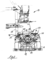
- a bottom frame 2 is seen in a nacelle (not shown) on a wind turbine (not shown), where the main shaft 4 of the turbine, with gear box 6 and the rotor 8 are shown, and where the main shaft fixture 10 according to the invention is shown in the mounted state, bearing a lightweight crane 12 and a self-hoisting crane 14 with a ground-based winch (not shown), respectively.
- the bottom frame 2 has for reasons of clarity been made transparent.
- the main shaft fixture 10 is in the shown embodiment shown anchored to the bottom frame 2 near the gear box 6 and near the rotor 8, and comprises a multi-part frame 14, which together with a cross member 16 fastened on it encloses a part of the main shaft 4 between the rotor 8 and the gear box 6.
- the multi-part frame 14 is anchored on the bottom frame 2.
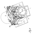
- fig. 2 is shown what are seen in fig. 1 , but as an end picture, seen from the rotor side of the shaft 4, and where the rotor 8 for reasons of clarity has been made transparent.
- the multi-part frame 14 and cross member 16 comprise in total four pressure mandrels 18 symmetrically placed around the main shaft 2, with tap shoes 20, that are engaged onto the main shaft 4 in order to fix such in place.
- the pressure mandrels 18 may be comprised of hydraulically driven pistons whose free ends comprise the tap shoes 20, but may also be executed in other manners, where they are moved manually between the active position where the tap shoes 20 are engaged with the main shaft 4 and the passive, withdrawn position.
- the main shaft fixture 10 comprises two parallel passing first beams 22 on each side of the main shaft 4, in the first ends of which, nearest to the rotor 8, a rotor lock is fastened in the form of a flange element 24, the hole circle 26 geometry of which is similar to the hole circle 28 geometry on the rotor 8 over a part of the periphery of the rotor. Locking of the rotor 8, the holes 7 in the rotor 8 and the holes 9 in the flange element 24 are brought to overlap, and subsequently bolts are inserted through the overlapping holes, which are tightened with nuts, after which the rotor 8 is fixed/locked by the flange element 24.
- the other end of the parallel passing first beams 22 are nearest to the gear box 6 are pivotally anchored on horizontally oriented bearing bolt 30, on a bracket 32, which is fastened to the bottom frame 2.
- the parallel passing first beams 22 are mutually connected with second cross members 34, on which bracket facilities 23 are seen for a self-hoisting crane 14 with a ground-based winch (not shown).
- an actuator 36 is located between the bottom frame 2 and the parallel passing first beams 22. Activation of the actuator 36 will result in a change of the distance between the bottom frame 2 and the first beams 22, in which the flange element 24 is suspended, which will cause the flange element 24 and the rotor 8 and thereby the main shaft 4 to be raised, which will result in the possibility to replace the main shaft's bearing 38 without the necessity of hoisting the main shaft 4 down to the ground, which is quite timesaving when the main shaft bearing 38 has to be repaired or replaced.
- the main shaft fixture 10 comprises mounting facilities 40 for the lightweight crane 12.
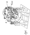
- FIG. 4 is shown an embodiment of the main shaft fixture according to the invention, which is specially suited for use for fixing the wind turbine's main shaft 4 in position on the nacelle, but where rotation of the main shaft 4 is possible, in the active position of the pressure mandrels/tap shoes (18, 20), engaged with the main shaft.
- a slideway lining 42, 44 is located between the opposing sides of the tap shoes 20 facing the surface of the main shaft 4.
- the slideway may be comprised of slide plates 42 that are fastened to the opposing free ends of the tap shoes 20 facing the main shaft 4, which in their active advanced position are engaged with the main shaft 4, but which alternatively may comprise a multi-part slide plate 44 cooperative working with the main shaft 4, for mounting on the main shaft 4, said multi-part slide plate 44 in its mounted state on the main shaft 4 cooperates with the tap shoes 20. It must be stated that the presence of the multi-part slide plate 44 on the main shaft 4 does not necessarily exclude the presence of the slide plates 42 and the tap shoes 20.
- the main shaft fixture 10 consists of a multi-part needle bearing/roller bearing/ball bearing 46, comprised of a multi-part inner ring 48 fastened on the main shaft as well as, a cooperating multi-part outer ring 50 consisting of bowed subsegments 52 of the number of tap shoes mounted on the opposing side of the tap shoes 20 facing the inner ring 48, which in the advanced position of the pressure mandrels form the outer ring 50 at a distance from the outer periphery of the multi-part inner ring 48, and where an appropriate number of needle rollers, rollers, or balls 54 (in the shown embodiment rollers 54) are arranged between the inner ring 48 and the outer ring 50, and where means (not shown) are present for retaining the needles/rollers or balls (54) in position between the inner ring 48 and outer ring 50.
- a multi-part needle bearing/roller bearing/ball bearing 46 comprised of a multi-part inner ring 48 fastened on the main shaft as well as, a cooperating multi
- the means mentioned for fastening of needle rollers/rollers/balls 54 may consist of cooperating edge delineators in opposing sides of the inner ring 48 and outer ring 50, alternatively of a means of holding between which the needle rollers/rollers/balls 54 are fastened.
- the main shaft fixture 10 can assume other embodiments than disclosed in the preceding and shown in the figures, however such do not change the inventive aspect that consists of specifying a main shaft fixture 10 of the given type that comprises adjustable pressure mandrels 18 with tap shoes 20, which causes the fixture 10 to be usable regardless of the geometry of the main shaft 4 on a wind turbine, and thus that such can be mounted without fixing the rotor 8 in place, and furthermore of combining the main shaft fixture with facilities 40 for mounting of a lightweight crane 12 and a self-hoisting crane 14 with a ground-based winch, respectively, as well as a rotor lock 24 and finally of furnishing the main shaft fixture 10 with actuators 36, enabling the main shaft 4 and the main shaft bearing 38 to be raised sufficiently from its bearing in the nacelle that it can be serviced or replaced.
- a main shaft fixture (10) for fixation of a main shaft (4) on a wind turbine during execution of installation and repair work on heavy parts of a wind turbine is disclosed, where the fixture (10) is divided up into a number of sections for mounting on stable structural parts (2) in a nacelle in a wind turbine, including the bottom frame (2) of the nacelle, where the main shaft fixture (10) comprises at least three radial displaceable pressure mandrels (18), substantially symmetrical located around the centre axis (11) of the main shaft, the ends of said pressure mandrels (18) facing the main shaft are furnished with a tap shoe (20), and said pressure mandrels (18) being displaceable between a passive, withdrawn lockable position where the tap shoes (20) are configured to be located at a distance from the surface of the main shaft (4) and an advanced lockable position where the tap shoes (20) are configured to be engaged with the main shaft (4).
Landscapes
- Engineering & Computer Science (AREA)
- Mechanical Engineering (AREA)
- General Engineering & Computer Science (AREA)
- Life Sciences & Earth Sciences (AREA)
- Sustainable Development (AREA)
- Sustainable Energy (AREA)
- Chemical & Material Sciences (AREA)
- Combustion & Propulsion (AREA)
- Wind Motors (AREA)
- Mounting Of Bearings Or Others (AREA)
- Massaging Devices (AREA)
- Orthopedics, Nursing, And Contraception (AREA)
Claims (12)
- Hauptwellenbefestigung (10) zur Befestigung einer Hauptwelle (4) an einer Windkraftanlage während der Ausführung von Installations- und Reparaturarbeiten an schweren Teilen einer Windkraftanlage, wobei die Befestigung (10) in eine Zahl von Abschnitten zum Montieren auf stabilen Strukturteilen (2) in einer Gondel einer Windkraftanlage unterteilt ist, die einen Bodenrahmen (2) der Gondel beinhalten, wobei die Hauptwellenbefestigung (10) einstellbare Druckdorne (18) mit Zapfenschuhen (20) umfasst, wobei die einstellbaren Druckdorne mit Zapfenschuhen zumindest drei radiale versetzbare Druckdorne (18) umfassen, die im Wesentlichen symmetrisch um die Mittelachse (11) der Hauptwelle liegen, die zu der Hauptwelle zeigenden Enden der Druckdorne (18) mit dem Zapfenschuh (20) ausgestattet sind und die Druckdorne (18) zwischen einer passiven Position, wo die Zapfenschuhe (20) dazu konfiguriert sind, in einem Abstand von der Oberfläche der Hauptwelle (4) zu liegen, und einer aktiven Position, wo die Zapfenschuhe (20) dazu konfiguriert sind, in die Hauptwelle (4) einzugreifen, versetzbar sind, gekennzeichnet dadurch, dass die Hauptwellenbefestigung ferner Montageeinrichtungen umfasst, die zum Verankern eines Selbsthebekrans und/oder eines Leichtkrans an/in einer Gondel einer Windkraftanlage geeignet sind.
- Hauptwellenbefestigung (10) nach Anspruch 1, gekennzeichnet dadurch, dass eine Winde des Selbsthebekrans auf der Bodenoberfläche nahe dem Fuß der Windkraftanlage liegt.
- Hauptwellenbefestigung (10) nach einem der Ansprüche 1 oder 2, gekennzeichnet dadurch, dass die Druckdorne (18) mit Aktoren zum Versetzen und Halten der Zapfenschuhe (20) in der passiven Position beziehungsweise der aktiven Position, alternativ in einer auswählbaren Position zwischen der passiven und der aktiven Position versehen sind.
- Hauptwellenbefestigung (10) nach einem der Ansprüche 1 bis 3, gekennzeichnet dadurch, dass die Druckdorne (18) aus Gewindebolzen bestehen, deren zu der Hauptwelle zeigende, entgegengesetzte freie Enden mit Zapfenschuhen (20) ausgestattet sind, und dass die Gewindebolzen mit Gewindelöchern in relevanten Abschnitten der Befestigung (10) zusammenwirken.
- Hauptwellenbefestigung (10) nach einem der Ansprüche 1-4, gekennzeichnet durch eine Gleitführungsauskleidung (42, 44), die zwischen den entgegengesetzten Seiten der Oberfläche der Hauptwelle und den Zapfenschuhen liegt
- Hauptwellenbefestigung (10) nach Anspruch 5, gekennzeichnet dadurch, dass die Gleitführungsauskleidung so konfiguriert ist, dass die zu der Hauptwelle (4) zeigenden, entgegengesetzten freien Enden der Zapfenschuhe (20) mit einer Gleitplatte (42) versehen sind, die in der aktiven Position in die Hauptwelle (4) eingreift.
- Hauptwellenbefestigung (10) nach Anspruch 5 oder 6, gekennzeichnet dadurch, dass sie eine mehrteilige Gleitplatte (44) umfasst, die mit der Hauptwelle (4) zum Montieren auf der Hauptwelle (4) zusammenwirkt, wobei die mehrteilige Gleitplatte (44) in ihrer montierten Position auf der Hauptwelle (4) mit den Zapfenschuhen (20) zusammenwirkt.
- Hauptwellenbefestigung (10) nach einem der Ansprüche 1-4, gekennzeichnet dadurch, dass sie ein mehrteiliges Nadellager, Walzenlager, Kugellager (46) umfasst, das aus einem mehrteiligen Innenring (48), der an der Hauptwelle (4) angebracht ist, und einem damit zusammenwirkenden mehrteiligen Außenring (50) besteht, der aus gebogenen Teilsegmenten (52) entsprechend der Zahl von Zapfenschuhen besteht, die an der zu dem Innenring (48) zeigenden, entgegengesetzten Seite der Zapfenschuhe (20) montiert sind, die in der aktiven Position der Druckdorne den Außenring (50) in einem Abstand von dem Außenumfang des mehrteiligen Innenrings (48) bilden, und wobei eine angemessene Zahl von Nadelwalzen, Walzen oder Kugeln (54) zwischen dem Innenring (48) und dem Außenring (50) angeordnet ist und wobei Mittel zum Halten der Nadeln, Walzen oder Kugeln (54) in Position zwischen dem Innenring (48) und dem Außenring (50) vorhanden sind.
- Hauptwellenbefestigung (10) nach einem der Ansprüche 1-8, gekennzeichnet dadurch, dass sie eine Rotorverriegelung (24) zur Befestigung des Rotors (8) der Windkraftanlage umfasst.
- Hauptwellenbefestigung (10) nach Anspruch 9, gekennzeichnet dadurch, dass die Rotorverriegelung (24) aus einem Flanschelement besteht, dessen Bolzenkreisgeometrie (26) einer Bolzenkreisgeometrie (28) an dem Rotor entspricht, wobei das Flanschelement (24) an den Enden an dem ersten Ende (21) von zwei ersten balkenförmigen Halterungen (22), die sich parallel zu und auf jeder Seite der Hauptwelle erstrecken, angebracht ist, wobei die balkenförmigen Halterungen (22) zu der Hauptwellenbefestigung gehören und wobei das andere Ende (23) der Halterungen (22) mit horizontal ausgerichteten Bolzenverbindungen (30) schwenkbar an anderen, zu der Hauptwellenbefestigung (10) gehörenden Halterungen (39) montiert ist, die angepasst sind, um an dem Bodenrahmen (2) der Gondel verankert zu sein.
- Hauptwellenbefestigung (10) nach Anspruch 10, gekennzeichnet dadurch, dass zumindest ein Aktor (36) am nächsten zur Rotorverriegelung (24) zwischen dem Bodenrahmen (2) der Gondel und der zum Bodenrahmen (2) zeigenden, angrenzenden Seite (25) der ersten balkenförmigen Halterungen (22) liegt, wobei der Aktor (36) zwischen einer ersten passiven äußeren Position und einer aktiven äußeren Position, wo das Flanschelement (24) vertikal versetzt ist, versetzbar ist.
- Baugruppe zum Installieren und Reparieren von schweren Teilen einer Windkraftanlage, die in einer Gondel einer Windkraftanlage angeordnet ist, wobei die Baugruppe eine Hauptwellenbefestigung nach einem der Ansprüche 1 bis 11 umfasst, gekennzeichnet dadurch, dass ein Selbsthebekran und/oder ein Leichtkran über die Montageeinrichtungen der Hauptwellenbefestigung an der Hauptwellenbefestigung montiert sind.
Priority Applications (1)
| Application Number | Priority Date | Filing Date | Title |
|---|---|---|---|
| EP25154572.9A EP4538530A3 (de) | 2014-10-07 | 2015-10-06 | Hauptwellenbefestigung |
Applications Claiming Priority (4)
| Application Number | Priority Date | Filing Date | Title |
|---|---|---|---|
| DKPA201400573A DK178466B1 (da) | 2014-10-07 | 2014-10-07 | Hovedaksel-fikstur til vindmøller. |
| DKPA201500527A DK201500527A1 (da) | 2014-10-07 | 2015-09-04 | Hovedakselfixstur til fiksering af hovedakslen på en vindmølle ved gennemførelse af montage- og reparationsarbejder. |
| PCT/DK2015/000040 WO2016055065A1 (en) | 2014-10-07 | 2015-10-06 | Main shaft fixture |
| EP15848694.4A EP3204639B1 (de) | 2014-10-07 | 2015-10-06 | Hauptwellenfixierung |
Related Parent Applications (1)
| Application Number | Title | Priority Date | Filing Date |
|---|---|---|---|
| EP15848694.4A Division EP3204639B1 (de) | 2014-10-07 | 2015-10-06 | Hauptwellenfixierung |
Related Child Applications (1)
| Application Number | Title | Priority Date | Filing Date |
|---|---|---|---|
| EP25154572.9A Division EP4538530A3 (de) | 2014-10-07 | 2015-10-06 | Hauptwellenbefestigung |
Publications (3)
| Publication Number | Publication Date |
|---|---|
| EP4198301A1 EP4198301A1 (de) | 2023-06-21 |
| EP4198301B1 true EP4198301B1 (de) | 2025-01-29 |
| EP4198301C0 EP4198301C0 (de) | 2025-01-29 |
Family
ID=55652612
Family Applications (3)
| Application Number | Title | Priority Date | Filing Date |
|---|---|---|---|
| EP22211827.5A Active EP4198301B1 (de) | 2014-10-07 | 2015-10-06 | Hauptwellenbefestigung |
| EP25154572.9A Pending EP4538530A3 (de) | 2014-10-07 | 2015-10-06 | Hauptwellenbefestigung |
| EP15848694.4A Active EP3204639B1 (de) | 2014-10-07 | 2015-10-06 | Hauptwellenfixierung |
Family Applications After (2)
| Application Number | Title | Priority Date | Filing Date |
|---|---|---|---|
| EP25154572.9A Pending EP4538530A3 (de) | 2014-10-07 | 2015-10-06 | Hauptwellenbefestigung |
| EP15848694.4A Active EP3204639B1 (de) | 2014-10-07 | 2015-10-06 | Hauptwellenfixierung |
Country Status (14)
| Country | Link |
|---|---|
| US (4) | US10378518B2 (de) |
| EP (3) | EP4198301B1 (de) |
| JP (1) | JP6648123B2 (de) |
| CN (1) | CN106795866B (de) |
| BR (1) | BR122022023804B1 (de) |
| CA (1) | CA2963016C (de) |
| DK (2) | DK201500527A1 (de) |
| ES (2) | ES2935584T3 (de) |
| MA (1) | MA40522A (de) |
| MX (2) | MX2017004689A (de) |
| PH (1) | PH12017500623B1 (de) |
| PL (1) | PL4198301T3 (de) |
| WO (1) | WO2016055065A1 (de) |
| ZA (1) | ZA201702109B (de) |
Families Citing this family (18)
| Publication number | Priority date | Publication date | Assignee | Title |
|---|---|---|---|---|
| DK201500527A1 (da) * | 2014-10-07 | 2016-04-18 | Liftra Ip Aps | Hovedakselfixstur til fiksering af hovedakslen på en vindmølle ved gennemførelse af montage- og reparationsarbejder. |
| DK179142B1 (da) * | 2015-12-03 | 2017-12-04 | Liftra Ip Aps | Løftebeslag |
| ES2859657T3 (es) * | 2016-08-26 | 2021-10-04 | Vestas Wind Sys As | Sistema de bloqueo de rotor para turbina eólica |
| EP3372550A1 (de) | 2017-03-10 | 2018-09-12 | LiftWerx Holdings Inc. | Hubsystem |
| US10337503B2 (en) * | 2017-04-27 | 2019-07-02 | General Electric Company | System and method for removing or installing a main shaft of a wind turbine with rigging |
| US10352305B2 (en) * | 2017-04-27 | 2019-07-16 | General Electric Company | System and method for removing or installing a main shaft of a wind turbine with a push/pull system configured at an end of the main shaft |
| US10422322B2 (en) * | 2017-04-27 | 2019-09-24 | General Electric Company | System and method for removing or installing a main shaft of a wind turbine with main shaft support elements |
| CA3012945C (en) | 2017-11-22 | 2019-05-21 | LiftWerx Holdings Inc. | Lift system mountable in a nacelle of a wind turbine |
| US10988351B2 (en) * | 2018-08-31 | 2021-04-27 | LiftWerx Holdings Inc. | Nacelle-mounted lift system for wind turbine |
| CA3151491A1 (en) * | 2019-09-12 | 2021-03-18 | LiftWerx Holdings Inc. | Support system for main shaft of wind turbine |
| CA3154176A1 (en) * | 2019-10-22 | 2022-04-29 | Glen D. Aitken | Lifting system for a rotor blade of a wind turbine |
| US12031519B2 (en) | 2020-02-17 | 2024-07-09 | Vestas Wind Systems A/S | Nacelle for a wind turbine and a method of making a wind turbine |
| WO2021168549A1 (en) | 2020-02-28 | 2021-09-02 | LiftWerx Holdings Inc. | Multiple up-tower lifting appliances on wind turbines |
| US11313356B2 (en) * | 2020-08-24 | 2022-04-26 | General Electric Company | Integrated system and method for servicing a component of a wind turbine |
| DK181017B1 (en) * | 2021-05-03 | 2022-09-26 | Liftra Ip Aps | Base for supporting a portable crane |
| EP4163491A1 (de) * | 2021-10-07 | 2023-04-12 | Liftra IP ApS | Verfahren zur durchführung von wartungsarbeiten an einer windturbine mit horizontaler achse |
| WO2024164064A1 (en) * | 2023-02-07 | 2024-08-15 | LiftWerx Holdings Inc. | Base for supporting a lift system in a nacelle of a wind turbine |
| CA3254190A1 (en) * | 2023-07-06 | 2025-07-04 | Liftwerx Solutions Inc. | Adjustable support system for main shaft of wind turbine |
Citations (17)
| Publication number | Priority date | Publication date | Assignee | Title |
|---|---|---|---|---|
| US510293A (en) | 1893-12-05 | Machine-vise | ||
| US716432A (en) | 1901-05-06 | 1902-12-23 | Albert Kingsbury | Center rest for lathes. |
| US1152271A (en) | 1913-03-15 | 1915-08-31 | Robert A Bisbee | Windmill-brake. |
| US2390888A (en) | 1943-11-01 | 1945-12-11 | Walter F Liber | Steady rest for lathes |
| US4177701A (en) | 1978-09-05 | 1979-12-11 | Dieter Christoph | Steady rest for use in apparatus for supporting and precision-turning of large rotary devices |
| JPS6154846A (ja) | 1984-08-24 | 1986-03-19 | Hitachi Ltd | 電動機のコロ軸受交換装置 |
| EP1677007A2 (de) | 2004-12-21 | 2006-07-05 | Gamesa Eolica, S.A. (Sociedad Unipersonal) | Windenergieanlage mit abnehmbarem Kran und Montageverfahren |
| EP1748182A2 (de) | 2005-07-27 | 2007-01-31 | General Electric Company | Verfahren sowie Vorrichtung zum Ersetzen von auf horizontalen Wellen in großer Höhe fixierten Objekten |
| DE102006013539A1 (de) | 2006-03-24 | 2007-09-27 | Nordex Energy Gmbh | Windenergieanlage mit einer Halteeinrichtung für eine Rotorwelle |
| US20090261594A1 (en) | 2004-12-17 | 2009-10-22 | Nordex Energy Gmbh | Wind motor with a holding device for a rotor shaft |
| US20100021278A1 (en) | 2008-07-24 | 2010-01-28 | Ge Wind Energy Gmbh | Portable crane system for wind turbine components |
| CN201483408U (zh) | 2009-10-13 | 2010-05-26 | 北京中能联创风电技术有限公司 | 单支撑主轴风力发电机组齿轮箱更换专用卡具 |
| US20110133473A1 (en) | 2010-04-21 | 2011-06-09 | Jonathan Paul Signore | Systems and methods for assembling a gearbox handling assembly for use in a wind turbine |
| US20120141292A1 (en) | 2011-09-20 | 2012-06-07 | Jonathan Paul Signore | Component handling system for use in wind turbines and methods of positioning a drive train component |
| WO2012105971A1 (en) | 2011-02-02 | 2012-08-09 | Smith Matthew K | Nacelle-mounted maintenance system for wind turbines |
| EP2784018A1 (de) | 2013-03-28 | 2014-10-01 | Mitsubishi Heavy Industries, Ltd. | Hubvorrichtung, Windturbinengenerator und Wartungsverfahren für einen Windturbinengenerator |
| US9909559B2 (en) | 2013-10-04 | 2018-03-06 | Inventus Holdings, Llc | Uptower wind turbine component replacement |
Family Cites Families (21)
| Publication number | Priority date | Publication date | Assignee | Title |
|---|---|---|---|---|
| US1853255A (en) * | 1928-03-07 | 1932-04-12 | Borden Co | Workholder |
| US3494230A (en) * | 1966-11-04 | 1970-02-10 | Star Shade Cutter Co | Automatic self-tightening chuck for shade cutting machines |
| DE3233915C2 (de) * | 1982-09-13 | 1987-02-12 | Oerlikon-Boehringer GmbH, 7320 Göppingen | Spannbacke für Aufspannvorrichtungen, insbesondere für Mehrbacken-Spannfutter von Werkzeugmaschinen |
| JPS61196072A (ja) * | 1985-02-25 | 1986-08-30 | 株式会社大林組 | 鉄塔の解体方法 |
| US4631995A (en) * | 1985-11-18 | 1986-12-30 | Vroenen John J | Tooling apparatus |
| US5015003A (en) * | 1988-08-03 | 1991-05-14 | Kennametal Inc. | Top jaw assembly with replaceable work holding pads |
| FR2771319B1 (fr) * | 1997-11-21 | 1999-12-31 | Protem Sa | Dispositif de serrage d'un organe tubulaire notamment au moyen de mors mobiles |
| DE19955516C1 (de) * | 1999-11-18 | 2001-12-20 | Tacke Windenergie Gmbh | Windkraftanlage und Verfahren zum Aus- und Einbau der Hauptkomponenten des Maschinengehäuses einer Windkraftanlage |
| JP3574377B2 (ja) * | 2000-06-05 | 2004-10-06 | 株式会社きんでん | 風力発電装置 |
| ES2320444T3 (es) | 2004-07-13 | 2009-05-22 | Eickhoff Maschinenfabrik Gmbh | Procedimiento y dispositivo para cambio de transmision en una instalacion eolica. |
| JP4885071B2 (ja) * | 2007-06-19 | 2012-02-29 | 三菱重工業株式会社 | 風車用設備の交換方法 |
| US8510943B2 (en) * | 2008-06-19 | 2013-08-20 | General Electric Company | Method for repairing a generator frame |
| CN201517466U (zh) * | 2009-08-07 | 2010-06-30 | 广东明阳风电技术有限公司 | 一种风力发电机的主轴锁定装置 |
| DK177083B1 (da) * | 2009-10-28 | 2011-06-27 | Liftra Aps | Indretning for tilvejebringelse af adgang og transport af gods til og fra en vindmøllekonstruktion over terrænniveau |
| JP5597410B2 (ja) * | 2010-02-18 | 2014-10-01 | Ntn株式会社 | 分割型保持器のセグメント及び転がり軸受 |
| WO2014103018A1 (ja) * | 2012-12-28 | 2014-07-03 | 三菱重工業株式会社 | 風力発電装置 |
| JP2014167273A (ja) * | 2013-02-28 | 2014-09-11 | Mitsubishi Heavy Ind Ltd | 風力発電装置 |
| DK201500527A1 (da) * | 2014-10-07 | 2016-04-18 | Liftra Ip Aps | Hovedakselfixstur til fiksering af hovedakslen på en vindmølle ved gennemførelse af montage- og reparationsarbejder. |
| US10422322B2 (en) * | 2017-04-27 | 2019-09-24 | General Electric Company | System and method for removing or installing a main shaft of a wind turbine with main shaft support elements |
| US10502195B2 (en) * | 2017-04-27 | 2019-12-10 | General Electric Company | Clamping apparatus for securing a main bearing of a wind turbine during an installation and/or repair procedure |
| US10781796B2 (en) * | 2017-07-11 | 2020-09-22 | General Electric Company | Clamping apparatus for positioning a main bearing of a wind turbine during an installation and/or repair procedure |
-
2015
- 2015-09-04 DK DKPA201500527A patent/DK201500527A1/da not_active Application Discontinuation
- 2015-10-06 MA MA040522A patent/MA40522A/fr unknown
- 2015-10-06 EP EP22211827.5A patent/EP4198301B1/de active Active
- 2015-10-06 CA CA2963016A patent/CA2963016C/en active Active
- 2015-10-06 ES ES15848694T patent/ES2935584T3/es active Active
- 2015-10-06 DK DK15848694.4T patent/DK3204639T3/da active
- 2015-10-06 JP JP2017518784A patent/JP6648123B2/ja active Active
- 2015-10-06 WO PCT/DK2015/000040 patent/WO2016055065A1/en not_active Ceased
- 2015-10-06 EP EP25154572.9A patent/EP4538530A3/de active Pending
- 2015-10-06 US US15/517,288 patent/US10378518B2/en active Active
- 2015-10-06 PL PL22211827.5T patent/PL4198301T3/pl unknown
- 2015-10-06 MX MX2017004689A patent/MX2017004689A/es unknown
- 2015-10-06 ES ES22211827T patent/ES3014914T3/es active Active
- 2015-10-06 CN CN201580054642.2A patent/CN106795866B/zh active Active
- 2015-10-06 EP EP15848694.4A patent/EP3204639B1/de active Active
- 2015-10-06 BR BR122022023804-1A patent/BR122022023804B1/pt active IP Right Grant
-
2017
- 2017-03-24 ZA ZA2017/02109A patent/ZA201702109B/en unknown
- 2017-04-05 PH PH12017500623A patent/PH12017500623B1/en unknown
- 2017-04-07 MX MX2023000217A patent/MX2023000217A/es unknown
-
2019
- 2019-06-26 US US16/452,617 patent/US20190316569A1/en not_active Abandoned
-
2024
- 2024-01-24 US US18/420,859 patent/US12104578B2/en active Active
- 2024-09-10 US US18/830,085 patent/US20250101958A1/en active Pending
Patent Citations (17)
| Publication number | Priority date | Publication date | Assignee | Title |
|---|---|---|---|---|
| US510293A (en) | 1893-12-05 | Machine-vise | ||
| US716432A (en) | 1901-05-06 | 1902-12-23 | Albert Kingsbury | Center rest for lathes. |
| US1152271A (en) | 1913-03-15 | 1915-08-31 | Robert A Bisbee | Windmill-brake. |
| US2390888A (en) | 1943-11-01 | 1945-12-11 | Walter F Liber | Steady rest for lathes |
| US4177701A (en) | 1978-09-05 | 1979-12-11 | Dieter Christoph | Steady rest for use in apparatus for supporting and precision-turning of large rotary devices |
| JPS6154846A (ja) | 1984-08-24 | 1986-03-19 | Hitachi Ltd | 電動機のコロ軸受交換装置 |
| US20090261594A1 (en) | 2004-12-17 | 2009-10-22 | Nordex Energy Gmbh | Wind motor with a holding device for a rotor shaft |
| EP1677007A2 (de) | 2004-12-21 | 2006-07-05 | Gamesa Eolica, S.A. (Sociedad Unipersonal) | Windenergieanlage mit abnehmbarem Kran und Montageverfahren |
| EP1748182A2 (de) | 2005-07-27 | 2007-01-31 | General Electric Company | Verfahren sowie Vorrichtung zum Ersetzen von auf horizontalen Wellen in großer Höhe fixierten Objekten |
| DE102006013539A1 (de) | 2006-03-24 | 2007-09-27 | Nordex Energy Gmbh | Windenergieanlage mit einer Halteeinrichtung für eine Rotorwelle |
| US20100021278A1 (en) | 2008-07-24 | 2010-01-28 | Ge Wind Energy Gmbh | Portable crane system for wind turbine components |
| CN201483408U (zh) | 2009-10-13 | 2010-05-26 | 北京中能联创风电技术有限公司 | 单支撑主轴风力发电机组齿轮箱更换专用卡具 |
| US20110133473A1 (en) | 2010-04-21 | 2011-06-09 | Jonathan Paul Signore | Systems and methods for assembling a gearbox handling assembly for use in a wind turbine |
| WO2012105971A1 (en) | 2011-02-02 | 2012-08-09 | Smith Matthew K | Nacelle-mounted maintenance system for wind turbines |
| US20120141292A1 (en) | 2011-09-20 | 2012-06-07 | Jonathan Paul Signore | Component handling system for use in wind turbines and methods of positioning a drive train component |
| EP2784018A1 (de) | 2013-03-28 | 2014-10-01 | Mitsubishi Heavy Industries, Ltd. | Hubvorrichtung, Windturbinengenerator und Wartungsverfahren für einen Windturbinengenerator |
| US9909559B2 (en) | 2013-10-04 | 2018-03-06 | Inventus Holdings, Llc | Uptower wind turbine component replacement |
Non-Patent Citations (3)
| Title |
|---|
| ANONYMOUS: "SELF-HOISTING CRANE - CHANGING GEARBOX, GENERATOR, ROTOR AND MAIN SHAFT", LIFTRA, 1 January 2013 (2013-01-01), XP093330203, Retrieved from the Internet <URL:https://eudp.dk/files/slutrapporter/liftra_self-hoisting-crane_screen_eng_1_21022014_1438.pdf> |
| D20 - NACELLE_DAVID BROCHURE (NO DATE) |
| DVORAK PAUL: "Power Climber Wind supplies over 1,000 nacelle davits in North America", WINDPOWERENGINEERING.COM, 24 January 2014 (2014-01-24), XP093330208, Retrieved from the Internet <URL:https://www.windpowerengineering.com/ower-climber-wind-supplies-1000-nacelle-davits-north-america/> |
Also Published As
Similar Documents
| Publication | Publication Date | Title |
|---|---|---|
| US12104578B2 (en) | Main shaft fixture | |
| JP5106619B2 (ja) | 風力発電装置及び風力発電装置のヨーベアリング交換方法 | |
| CA2960487C (en) | System and method for removing and/or installing a rotor blade of a wind turbine | |
| US20140377062A1 (en) | Device and method for rotating a rotor of a wind turbine | |
| CN102422016A (zh) | 叶片安装 | |
| EP3139058B1 (de) | Wartungssystem und verfahren zur wartung einer bremsvorrichtung eines bremssystems mit einer horizontal angeordneten bremsscheibe | |
| EP3078847B1 (de) | Wartungswerkzeug für ein planetengetriebe und wartungsverfahren | |
| MX2013012638A (es) | Instalacion de energia eolica. | |
| TWI885754B (zh) | 用於降及/或升風力渦輪機轉子葉片的方法以及用於維修風力渦輪機轉子葉片的方法 | |
| EP2607684B1 (de) | Mittel zum Drehen des Rotors einer Windturbine und Verfahren zum Drehen des Rotors | |
| CN206230223U (zh) | 用于拆卸锁定销的拆卸装置 | |
| BR112017007156B1 (pt) | Acessório de eixo principal |
Legal Events
| Date | Code | Title | Description |
|---|---|---|---|
| PUAI | Public reference made under article 153(3) epc to a published international application that has entered the european phase |
Free format text: ORIGINAL CODE: 0009012 |
|
| STAA | Information on the status of an ep patent application or granted ep patent |
Free format text: STATUS: THE APPLICATION HAS BEEN PUBLISHED |
|
| AC | Divisional application: reference to earlier application |
Ref document number: 3204639 Country of ref document: EP Kind code of ref document: P |
|
| AK | Designated contracting states |
Kind code of ref document: A1 Designated state(s): AL AT BE BG CH CY CZ DE DK EE ES FI FR GB GR HR HU IE IS IT LI LT LU LV MC MK MT NL NO PL PT RO RS SE SI SK SM TR |
|
| STAA | Information on the status of an ep patent application or granted ep patent |
Free format text: STATUS: REQUEST FOR EXAMINATION WAS MADE |
|
| 17P | Request for examination filed |
Effective date: 20231221 |
|
| RBV | Designated contracting states (corrected) |
Designated state(s): AL AT BE BG CH CY CZ DE DK EE ES FI FR GB GR HR HU IE IS IT LI LT LU LV MC MK MT NL NO PL PT RO RS SE SI SK SM TR |
|
| STAA | Information on the status of an ep patent application or granted ep patent |
Free format text: STATUS: EXAMINATION IS IN PROGRESS |
|
| 17Q | First examination report despatched |
Effective date: 20240305 |
|
| GRAP | Despatch of communication of intention to grant a patent |
Free format text: ORIGINAL CODE: EPIDOSNIGR1 |
|
| STAA | Information on the status of an ep patent application or granted ep patent |
Free format text: STATUS: GRANT OF PATENT IS INTENDED |
|
| INTG | Intention to grant announced |
Effective date: 20241106 |
|
| GRAS | Grant fee paid |
Free format text: ORIGINAL CODE: EPIDOSNIGR3 |
|
| GRAA | (expected) grant |
Free format text: ORIGINAL CODE: 0009210 |
|
| STAA | Information on the status of an ep patent application or granted ep patent |
Free format text: STATUS: THE PATENT HAS BEEN GRANTED |
|
| AC | Divisional application: reference to earlier application |
Ref document number: 3204639 Country of ref document: EP Kind code of ref document: P |
|
| AK | Designated contracting states |
Kind code of ref document: B1 Designated state(s): AL AT BE BG CH CY CZ DE DK EE ES FI FR GB GR HR HU IE IS IT LI LT LU LV MC MK MT NL NO PL PT RO RS SE SI SK SM TR |
|
| REG | Reference to a national code |
Ref country code: GB Ref legal event code: FG4D |
|
| REG | Reference to a national code |
Ref country code: CH Ref legal event code: EP |
|
| REG | Reference to a national code |
Ref country code: IE Ref legal event code: FG4D |
|
| REG | Reference to a national code |
Ref country code: DE Ref legal event code: R096 Ref document number: 602015090958 Country of ref document: DE |
|
| U01 | Request for unitary effect filed |
Effective date: 20250225 |
|
| U07 | Unitary effect registered |
Designated state(s): AT BE BG DE DK EE FI FR IT LT LU LV MT NL PT RO SE SI Effective date: 20250304 |
|
| PG25 | Lapsed in a contracting state [announced via postgrant information from national office to epo] |
Ref country code: RS Free format text: LAPSE BECAUSE OF FAILURE TO SUBMIT A TRANSLATION OF THE DESCRIPTION OR TO PAY THE FEE WITHIN THE PRESCRIBED TIME-LIMIT Effective date: 20250429 |
|
| PG25 | Lapsed in a contracting state [announced via postgrant information from national office to epo] |
Ref country code: NO Free format text: LAPSE BECAUSE OF FAILURE TO SUBMIT A TRANSLATION OF THE DESCRIPTION OR TO PAY THE FEE WITHIN THE PRESCRIBED TIME-LIMIT Effective date: 20250429 Ref country code: IS Free format text: LAPSE BECAUSE OF FAILURE TO SUBMIT A TRANSLATION OF THE DESCRIPTION OR TO PAY THE FEE WITHIN THE PRESCRIBED TIME-LIMIT Effective date: 20250529 |
|
| PG25 | Lapsed in a contracting state [announced via postgrant information from national office to epo] |
Ref country code: HR Free format text: LAPSE BECAUSE OF FAILURE TO SUBMIT A TRANSLATION OF THE DESCRIPTION OR TO PAY THE FEE WITHIN THE PRESCRIBED TIME-LIMIT Effective date: 20250129 |
|
| PG25 | Lapsed in a contracting state [announced via postgrant information from national office to epo] |
Ref country code: GR Free format text: LAPSE BECAUSE OF FAILURE TO SUBMIT A TRANSLATION OF THE DESCRIPTION OR TO PAY THE FEE WITHIN THE PRESCRIBED TIME-LIMIT Effective date: 20250430 |
|
| PG25 | Lapsed in a contracting state [announced via postgrant information from national office to epo] |
Ref country code: SM Free format text: LAPSE BECAUSE OF FAILURE TO SUBMIT A TRANSLATION OF THE DESCRIPTION OR TO PAY THE FEE WITHIN THE PRESCRIBED TIME-LIMIT Effective date: 20250129 |
|
| PGFP | Annual fee paid to national office [announced via postgrant information from national office to epo] |
Ref country code: PL Payment date: 20250925 Year of fee payment: 11 |
|
| PG25 | Lapsed in a contracting state [announced via postgrant information from national office to epo] |
Ref country code: CZ Free format text: LAPSE BECAUSE OF FAILURE TO SUBMIT A TRANSLATION OF THE DESCRIPTION OR TO PAY THE FEE WITHIN THE PRESCRIBED TIME-LIMIT Effective date: 20250129 |
|
| PLBI | Opposition filed |
Free format text: ORIGINAL CODE: 0009260 |
|
| PG25 | Lapsed in a contracting state [announced via postgrant information from national office to epo] |
Ref country code: SK Free format text: LAPSE BECAUSE OF FAILURE TO SUBMIT A TRANSLATION OF THE DESCRIPTION OR TO PAY THE FEE WITHIN THE PRESCRIBED TIME-LIMIT Effective date: 20250129 |
|
| PLAB | Opposition data, opponent's data or that of the opponent's representative modified |
Free format text: ORIGINAL CODE: 0009299OPPO |
|
| PLAX | Notice of opposition and request to file observation + time limit sent |
Free format text: ORIGINAL CODE: EPIDOSNOBS2 |
|
| 26 | Opposition filed |
Opponent name: LIFTOFF-MCE B.V. Effective date: 20251023 |
|
| R26 | Opposition filed (corrected) |
Opponent name: LIFTOFF-MCE B.V. Effective date: 20251023 |
|
| U20 | Renewal fee for the european patent with unitary effect paid |
Year of fee payment: 11 Effective date: 20251028 |
|
| PGFP | Annual fee paid to national office [announced via postgrant information from national office to epo] |
Ref country code: GB Payment date: 20251022 Year of fee payment: 11 |