EP2607684B1 - Mittel zum Drehen des Rotors einer Windturbine und Verfahren zum Drehen des Rotors - Google Patents
Mittel zum Drehen des Rotors einer Windturbine und Verfahren zum Drehen des Rotors Download PDFInfo
- Publication number
- EP2607684B1 EP2607684B1 EP11194370.0A EP11194370A EP2607684B1 EP 2607684 B1 EP2607684 B1 EP 2607684B1 EP 11194370 A EP11194370 A EP 11194370A EP 2607684 B1 EP2607684 B1 EP 2607684B1
- Authority
- EP
- European Patent Office
- Prior art keywords
- rotor
- linear actuator
- wind turbine
- generator
- brake disc
- Prior art date
- Legal status (The legal status is an assumption and is not a legal conclusion. Google has not performed a legal analysis and makes no representation as to the accuracy of the status listed.)
- Not-in-force
Links
- 238000000034 method Methods 0.000 title claims description 8
- 230000003213 activating effect Effects 0.000 claims description 2
- 238000009434 installation Methods 0.000 description 10
- 238000010276 construction Methods 0.000 description 3
- 238000012423 maintenance Methods 0.000 description 3
- 230000001419 dependent effect Effects 0.000 description 1
- 230000000694 effects Effects 0.000 description 1
- 238000011065 in-situ storage Methods 0.000 description 1
Images


Classifications
-
- F—MECHANICAL ENGINEERING; LIGHTING; HEATING; WEAPONS; BLASTING
- F03—MACHINES OR ENGINES FOR LIQUIDS; WIND, SPRING, OR WEIGHT MOTORS; PRODUCING MECHANICAL POWER OR A REACTIVE PROPULSIVE THRUST, NOT OTHERWISE PROVIDED FOR
- F03D—WIND MOTORS
- F03D1/00—Wind motors with rotation axis substantially parallel to the air flow entering the rotor
- F03D1/06—Rotors
- F03D1/065—Rotors characterised by their construction elements
- F03D1/0658—Arrangements for fixing wind-engaging parts to a hub
-
- F—MECHANICAL ENGINEERING; LIGHTING; HEATING; WEAPONS; BLASTING
- F03—MACHINES OR ENGINES FOR LIQUIDS; WIND, SPRING, OR WEIGHT MOTORS; PRODUCING MECHANICAL POWER OR A REACTIVE PROPULSIVE THRUST, NOT OTHERWISE PROVIDED FOR
- F03D—WIND MOTORS
- F03D13/00—Assembly, mounting or commissioning of wind motors; Arrangements specially adapted for transporting wind motor components
- F03D13/10—Assembly of wind motors; Arrangements for erecting wind motors
-
- F—MECHANICAL ENGINEERING; LIGHTING; HEATING; WEAPONS; BLASTING
- F05—INDEXING SCHEMES RELATING TO ENGINES OR PUMPS IN VARIOUS SUBCLASSES OF CLASSES F01-F04
- F05B—INDEXING SCHEME RELATING TO WIND, SPRING, WEIGHT, INERTIA OR LIKE MOTORS, TO MACHINES OR ENGINES FOR LIQUIDS COVERED BY SUBCLASSES F03B, F03D AND F03G
- F05B2260/00—Function
- F05B2260/30—Retaining components in desired mutual position
- F05B2260/31—Locking rotor in position
-
- Y—GENERAL TAGGING OF NEW TECHNOLOGICAL DEVELOPMENTS; GENERAL TAGGING OF CROSS-SECTIONAL TECHNOLOGIES SPANNING OVER SEVERAL SECTIONS OF THE IPC; TECHNICAL SUBJECTS COVERED BY FORMER USPC CROSS-REFERENCE ART COLLECTIONS [XRACs] AND DIGESTS
- Y02—TECHNOLOGIES OR APPLICATIONS FOR MITIGATION OR ADAPTATION AGAINST CLIMATE CHANGE
- Y02E—REDUCTION OF GREENHOUSE GAS [GHG] EMISSIONS, RELATED TO ENERGY GENERATION, TRANSMISSION OR DISTRIBUTION
- Y02E10/00—Energy generation through renewable energy sources
- Y02E10/70—Wind energy
- Y02E10/72—Wind turbines with rotation axis in wind direction
Definitions
- the invention relates to means to rotate the rotor of a wind turbine and a method to rotate the rotor.
- a wind turbine transfers the energy of the wind into electrical energy.
- the wind turbine comprises a nacelle that is connected to a tower and a rotor that is connected to the nacelle.
- the rotor comprises a hub that is rotatable mounted to the nacelle and at least one rotor blade mounted to the hub.
- the wind interacts with the rotor blade of the wind turbine in a way that the rotor rotates.
- the rotation of the rotor is transferred to an electrical generator.
- the tower When the wind turbine is erected, the tower is set up and the nacelle is mounted onto the tower.
- the hub is mounted to the nacelle and the at least one rotor blade is mounted to the hub.
- the at least one rotor blade is hoisted up by a crane and connected to the hub.
- the hub has to be in a predetermined angular rotational position around it's axis of rotation to establish the connection between the hub and the rotor blade.
- This position corresponds to the direction of the blade during the fastening of the connection.
- the position can be a horizontal or a vertical arrangement of the hub and the rotor blade for example.
- the hub has to be rotated to establish the connection between the hub and a first rotor blade. In the case of more then one rotor blade that has to be mounted, the position of the hub has to be changed.
- the hub has to be rotated form the first into a second position to establish the connection between the hub and the second rotor blade.
- US 2006/0147308 A1 describes a method of mounting rotor blades to a rotor hub which is connected to a pod of a wind turbine power installation, including the following steps: rotating the rotor hub into a predetermined first position, fitting a rotor blade, rotating the rotor hub by means of the rotor blade into a predetermined second position, and mounting a second rotor blade, wherein the rotation of the rotor hub is effected in the direction of the effect of gravitational force of the first rotor blade which is already mounted.
- a rotation of the hub is necessary for the installation of the blades, but it can also be necessary before or after the installation of the blades. This can be during the installation of at least a segment of the generator, during maintenance and service, or for the dismantling of the wind turbine.
- WO 2010/103086 A2 describes an arrangement for in situ mounting of rotor blades to a rotor of a wind power plant comprising rotor blades, a rotor hub, a disc, a means for rotation of the disc around its axis.
- the disc is in connection with the rotor hub in such a way that when the disc rotates a certain degree of angle around its axis it will cause the rotor hub to rotate the same degree of an angle around the axis of the rotor hub.
- the means for rotation comes into a desired position, the disc is secured by securing means.
- a direct driven wind turbine comprises an electrical generator with a rotor and a stator, a hub constructed to receive a rotor blade, and actuator means, whereby the hub is connected to the rotor of the electrical generator.
- the hub and the rotor of the electrical generator are rotatable mounted to the stator of the generator.
- the actuator means are constructed and arranged to rotate the rotor of the electrical generator in respect to the stator of the electrical generator, whereby the actuator means comprise a linear actuator and the linear actuator rotates the rotor of the generator.
- the linear actuator is small enough to be placed to act between the rotor and the stator.
- the linear actuator can be attached to the rotor and the stator or to constructive parts attached to the rotor and the stator. When the linear actuator is activated, it pushes or pulls the rotor in respect to the stator.
- linear actuator does not need extra space that has to be provided inside the wind turbine.
- linear actuator can be attached easily and does not need extensive additional constructive elements to act of the rotor and the stator.
- the rotor of the electrical generator including the hub can be rotated in respect to the stator of the electrical generator.
- the rotor can be positioned in respect to the stator.
- the hub can be rotated into a predetermined position to attach or detach a rotor blade to the hub.
- the linear actuator comprises a first end and a second end and an intermediate part, which is arranged between the first and the second end, while the intermediate part comprises a drive that is constructed in a way to change the distance between the first end and the second end.
- the drive in the intermediate part of the linear actuator changes the distance between the first end and the second end.
- the first end and the second end of the linear actuator are attached to or close to the rotor and the stator of the generator.
- the linear actuator can push or pull the second end in respect to the first end.
- the linear actuator can push or pull the rotor in respect to the stator of the generator of the wind turbine.
- stator of the generator is attached to a support structure and the first end of the linear actuator is detachably attached to the support structure.
- the stator of the generator is connected to the support structure.
- the support structure is connected at least indirectly to the tower.
- the support structure is rigid enough to carry the stator and the rotor including.the hub and the rotor blades of the wind turbine.
- the support structure is rigid enough to take the loads of accelerating or braking the rotor of the generator including the hub.
- the support structure is accessible in the nacelle of the wind turbine. Thus the accessibility of the support structure for personnel to attach and detach the linear actuator is good.
- the linear actuator can be mounted to the support structure without major changes in the construction of the support structure and without major changes in the construction of the wind turbine as such. Thus no or only small changes are necessary in the construction of the support structure to attach the linear actuator.
- a brake disc is connected to the rotor and the second end of the linear actuator is detachably attached to the brake disc.
- a brake disc is attached to the rotor of the wind turbine. Brakes are attached at a stationary part of the wind turbine like the support structure.
- the brake disc is constructed in a way that the rotation of the rotor including the hub and the rotor blades can be slowed down and stopped. Thus the brake disc is rigid enough to be used to move the rotor. Thus no additional attachment point at the rotor is needed.
- the accessibility for personnel to the brake disc and brakes is very good as the brakes are subject to regular service.
- the brake disc is designed in a way that it can be reached easily.
- the linear actuator can be attached and detaches to the brake disc easily by personnel in the nacelle of the wind turbine.
- the second end of the linear actuator comprises a caliper that is constructed in a way to be connected to the brake disc.
- the brake disc is designed and constructed in a way that the calipers of the brake operate on the surface of the brake disc.
- this calipers act on the brake disc like the calipers of the brake.
- no additional point of attachment is necessary at the brake disc or at the rotor of the generator to attach the linear actuator.
- the brake disc comprises cut-outs and the calipers of the linear actuator interact with at least one of the cut-outs.
- the brake disc of the rotor normally comprises cut-outs, at the rim of in the disc like holes, that are used for locking the rotor in a certain position after stopping the rotor.
- These cut-outs can be used as attachment points to connect the calipers of the linear actuator to the brake disc. Therefore the calipers can be equipped with additional bolts to interact with the cut-outs.
- the transfer of the force to accelerate or slow down the movement of the rotor can be increased.
- the connection of the calipers to the brake disc is tighter and saver.
- the calipers can be constructed smaller in size, as not the whole force is transferred by friction only.
- the linear actuator comprises a drive to activate and deactivate the caliper.
- the operation of the calipers can be motorized.
- the operation of the calipers can be automated and controlled.
- a remote control of the operation of the calipers is possible.
- the drive is a pneumatic drive, a hydraulic drive or an electric drive.
- a pneumatic, hydraulic and/or electric system is normally already present in the wind turbine and often already installed and in use when the rotor blades are mounted to the hub of the wind turbine.
- a connection to an existing and working system can be used to activate the calipers of the linear actuator.
- the drive of the intermediate part of the linear actuator comprises a pneumatic or hydraulic cylinder or an electrical drive.
- a pneumatic, hydraulic and/or electric system is normally already present in the wind turbine and often already installed and in use when the rotor blades are mounted to the hub of the wind turbine.
- a connection to an existing and working system can be used to activate the drive in the linear actuator.
- the linear actuator is constructed and controlled in a way that the distance between the first end of the linear actuator and the second end can be set to a predetermined value, so that the second end of the linear actuator and/or the brake disc of the rotor, that is connected to the second end of the linear actuator, can be positioned in respect to the first end.
- the distance between the first end and the second end can be set to a predetermined value by activating the drive in the intermediate part of the linear actuator.
- the distance between the first and the second end can be controlled.
- the distance between the point where the first end is attached to and the point where the second end is attached to can be controlled.
- the rotational position of the rotor in respect to the stator can be controlled.
- the rotational movement of the rotor of the wind turbine can be controlled.
- the rotor of a direct driven wind turbine is rotated by rotating the rotor of the generator in respect to the stator of the generator by use of the linear actuator.
- the linear actuator rotates the rotor of the generator of the wind turbine.
- the rotor of the direct driven wind turbine can be rotated by rotating the rotor of the generator of the wind turbine.
- the rotor of a direct driven wind turbine is rotated by rotating the rotor of the generator in respect to the stator of the generator in a stepwise motion.
- the rotation of the rotor is performed by the use of a linear actuator.
- the linear actuator is detached at least from one of the rotor or the actuator and is retracted to the original position. Thereafter it is connected again for another movement of the rotor. This leads to a stepwise rotation of the rotor.
- the method comprises the steps of attaching the caliper to the brake disc while the caliper is in a first position in relation to the support structure.
- the linear actuator is activated to increase or decrease the distance between the first end and the second end of the linear actuator, so that the caliper move from a first position to a second position in relation to the support structure, whereby the linear actuator pushes or pulls the rotor, and the rotor rotates in respect to the stator of the electrical generator.
- a rotation of the hub is necessary for the installation of the blades, but it can also be necessary before or after the installation of the blades. It can also be necessary during the installation of at least a segment of the generator, during maintenance and service, or for the dismantling of the wind turbine.
- FIG 1 shows a wind turbine 1 with a tower 2, an electrical generator 3 and a hub 4. At the hub 4 are receiving spots 5 where rotor blades will be connected. A rotor blade 6 is carried in a lifting device 7 that is lifted up by a crane 8.
- the rotor blade 6 is connected to one of the receiving spots 5.
- a second rotor blade 6 can be attached to the hub 4 without moving the crane to another location, after the hub 4 is rotated.
- the hub has to be rotated by 120 degree, so that the receiving spot 5 of the second rotor blade is in the same position as the receiving spot 5 of the first rotor blade was, when the first rotor blade was attached.
- FIG 2 shows a cut through a hub and a generator of a direct driven wind turbine.
- FIG 2 shows a cut through a hub 4 and a generator 3 of a direct driven wind turbine.
- the cut is along the axis of rotation of the generator 3.
- the generator comprises a rotor 9 and a stator 10.
- the stator 10 is connected to a support structure 13. Attached to the rotor 9 of the generator 3 is a brake disc 12.
- a brake 11 is attached to the support structure 13.
- the brake 11 interacts with the brake disc 12 to brake the rotation of the rotor 9 of the generator 3.
- a locking mechanism (not shown) that locks the position of the rotor 9 of the generator 3 in relation to the stator 10.
- FIG 3 shows the linear actuator
- Fig 3 shows a detail of the support structure 13 and the brake disc 12 of the generator of the wind turbine.
- the brake disc 12 is mounted to the rotor of the generator.
- the brake disc 12 shows several cut outs 14 that are used by the locking mechanism. A bolt of the locking mechanism is pushed into the cut out 14 of the brake disc 12 to lock the rotation of the rotor of the generator.
- the locking mechanism with the bolt is connected to the support structure 13 of the wind turbine.
- Fig 3 shows a linear actuator 15 that is detachably connected at a connection point 16 to the support structure 13 of the wind turbine with its first end.
- the linear actuator 15 comprises calipers 18 at its second end that are constructed to attach to the brake disc 12 and lock into the cut outs 14 present in the brake disc 12.
- the calipers 18 can be opened and closed by a drive 19.
- the linear actuator 15 comprises a hydraulic cylinder 17.
- calipers 18 are open and the hydraulic cylinder 17 is completely retracted.
- FIG 4 shows the linear actuator in a second step.
- FIG 4 shows the linear actuator 15 when the hydraulic cylinder 17 is completely retracted.
- the calipers 18 are closed by the drive 19 to attach to the brake disc 12 and lock into the cut outs 14 of the brake disc 12.
- the movement of the calipers 18 is according to the arrows.
- FIG 5 shows the linear actuator in a third step.
- FIG 5 shows the linear actuator 15 in a third step.
- the calipers 18 of the linear actuator 15 are engaged to the brake disc 12 and the cut outs 14.
- the hydraulic cylinder 17 is now extending. It is pushing the piston 22 in the direction of the arrow 20. As the calipers 18 are locked to the brake disc 12, the rotor 9 with the brake disc 12 is pushed in the direction of the arrow 21.
- the rotor 9 is pushed and rotates a predetermined part of a rotation.
- FIG 6 shows the linear actuator in a fourth step.
- FIG 6 shows the linear actuator 15 after the piston 22 is extended.
- the brake 11 is engaged to stop the rotation.
- the calipers of the brake 11 are attached to the brake disc 12 in the direction of the arrows 23 and 24.
- the locking mechanism 25 locks the rotor 9 to the support structure 13 to avoid a further movement of the rotor 9.
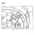
- FIG 7 shows the linear actuator in a fifth step.
- FIG 7 shows the linear actuator 15 after the rotor 9 has been locked to the support structure 13 by the locking mechanism 25.
- the calipers 18 are disengaged along the arrows 26 by help of the drive 19.
- the linear actuator is now no longer attached to the brake disc 12 and the cut outs 14.
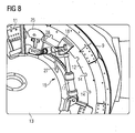
- FIG 8 shows the linear actuator in a sixth step.
- FIG 8 shows the linear actuator 15 after the calipers 18 were disengaged from the brake disc 12.
- the hydraulic cylinder 17 is retracted along the direction of arrow 27.
- the calipers 18 are disengaged from the brake disc 12 and slide along the brake disc 12 back into the original position described in FIG 3 .
- the calibers 18 can be closed again to engage with the brake disc 12 and the cut outs 14.
- the brake 11 and the locking mechanism 25 can then be disengaged and the linear actuator 15 is ready to push the rotor 9 a predetermined part of a rotation.
- FIG 9 shows the use of two linear actuators at the brake disc of the wind turbine.
- FIG 9 shows two linear actuators 15 that are attached to the support structure 13 and are acting on the brake disc 12 to push the rotor 9.
- the support structure 13 is connected to the tower 2 of the wind turbine.
Claims (9)
- Getriebelose Windenergieanlage (1),- die einen elektrischen Generator (3) mit einem Rotor (9) und einem Stator (10), eine Nabe (4), die so konstruiert ist, dass sie ein Rotorblatt (6) aufnimmt, und Stellgliedmittel umfasst,- wobei die Nabe (4) mit dem Rotor (9) des elektrischen Generators (3) verbunden ist,- wobei die Nabe (4) und der Rotor (9) des elektrischen Generators (3) drehbar an dem Stator (10) des Generators (3) angebracht sind,- wobei die Stellgliedmittel so konstruiert und angeordnet sind, dass sie den Rotor (9) des elektrischen Generators (3) in Bezug zu dem Stator (10) des elektrischen Generators (3) drehen,- wobei die Stellgliedmittel ein lineares Stellglied (15) umfassen und das lineare Stellglied (15) den Rotor (9) des Generators (3) dreht,- wobei das lineare Stellglied (15) ein erstes Ende und ein zweites Ende sowie einen Zwischenteil umfasst, der zwischen dem ersten und dem zweiten Ende angeordnet ist, während der Zwischenteil einen Antrieb (17) umfasst, der so konstruiert ist, dass er den Abstand zwischen dem ersten und dem zweiten Ende ändert,- wobei eine Bremsscheibe (12) mit dem Rotor (9) verbunden und das zweite Ende des linearen Stellglieds (15) abnehmbar an der Bremsscheibe (12) befestigt ist,- dadurch gekennzeichnet, dass das zweite Ende des linearen Stellglieds einen Sattel (18) umfasst, der so konstruiert ist, dass er mit der Bremsscheibe (12) verbunden wird.
- Getriebelose Windenergieanlage (1) nach Anspruch 1, bei der der Stator (10) des Generators (3) an einer Trägerkonstruktion (13) befestigt und das erste Ende des linearen Stellglieds (15) abnehmbar an der Trägerkonstruktion (13) befestigt ist.
- Getriebelose Windenergieanlage (1) nach einem der vorhergehenden Ansprüche, bei der die Bremsscheibe (12) Aussparungen (14) umfasst und die Sättel (18) des linearen Stellglieds (15) mit mindestens einer der Aussparungen (14) zusammenwirken.
- Getriebelose Windenergieanlage (1) nach einem der vorhergehenden Ansprüche, bei der das lineare Stellglied (15) einen Antrieb (19) zum Aktivieren und Deaktivieren des Sattels (18) umfasst.
- Getriebelose Windenergieanlage (1) nach Anspruch 4, bei der es sich bei dem Antrieb (19) um einen pneumatischen, einen hydraulischen oder einen elektrischen Antrieb handelt.
- Getriebelose Windenergieanlage (1) nach einem der vorhergehenden Ansprüche, bei der der Antrieb (17) des Zwischenteils des linearen Stellglieds (15) einen Pneumatik- oder Hydraulikzylinder oder einen elektrischen Antrieb umfasst.
- Getriebelose Windenergieanlage (1) nach einem der vorhergehenden Ansprüche, bei der das lineare Stellglied (15) so konstruiert ist und gesteuert wird, dass der Abstand zwischen dem ersten Ende des linearen Stellglieds und dem zweiten Ende auf einen vorgegebenen Wert eingestellt werden kann, so dass das zweite Ende des linearen Stellglieds (15) und/ oder die Bremsscheibe (12) des Rotors, die mit dem zweiten Ende des linearen Stellglieds (15) verbunden ist, in Bezug auf das erste Ende positioniert werden kann.
- Verfahren zum Drehen des Rotors (9) einer getriebelosen Windenergieanlage (1) nach einem der vorhergehenden Ansprüche durch- Drehen des Rotors (9) des Generators (3) in Bezug zum Stator (10) des Generators (3) unter Einsatz des linearen Stellglieds (15),- Befestigen des Sattels (18) an der Bremsscheibe (12), während er sich in einer ersten Position in Bezug zur Trägerkonstruktion (13) befindet,- Aktivieren des linearen Stellglieds (15) zum Erhöhen oder Verringern des Abstands zwischen dem ersten und dem zweiten Ende des linearen Stellglieds (15), so dass sich der Sattel (18) aus einer ersten in eine zweite Position in Bezug auf die Trägerkonstruktion (13) bewegt, wodurch das lineare Stellglied (15) den Rotor (9) schiebt oder zieht und sich der Rotor (9) in Bezug auf den Stator (10) des elektrischen Generators (3) dreht.
- Verfahren zum Drehen eines Rotors (9) einer getriebelosen Windenergieanlage (1) nach Anspruch 8, das die Schritte zum schrittweisen Drehen des Rotors (9) des Generators (3) in Bezug zum Stator (10) des Generators (3) umfasst.
Priority Applications (2)
| Application Number | Priority Date | Filing Date | Title |
|---|---|---|---|
| EP11194370.0A EP2607684B1 (de) | 2011-12-19 | 2011-12-19 | Mittel zum Drehen des Rotors einer Windturbine und Verfahren zum Drehen des Rotors |
| DK11194370T DK2607684T3 (en) | 2011-12-19 | 2011-12-19 | Means for rotation of the rotor of a wind turbine and method for the rotation of the rotor |
Applications Claiming Priority (1)
| Application Number | Priority Date | Filing Date | Title |
|---|---|---|---|
| EP11194370.0A EP2607684B1 (de) | 2011-12-19 | 2011-12-19 | Mittel zum Drehen des Rotors einer Windturbine und Verfahren zum Drehen des Rotors |
Publications (2)
| Publication Number | Publication Date |
|---|---|
| EP2607684A1 EP2607684A1 (de) | 2013-06-26 |
| EP2607684B1 true EP2607684B1 (de) | 2015-04-01 |
Family
ID=45349080
Family Applications (1)
| Application Number | Title | Priority Date | Filing Date |
|---|---|---|---|
| EP11194370.0A Not-in-force EP2607684B1 (de) | 2011-12-19 | 2011-12-19 | Mittel zum Drehen des Rotors einer Windturbine und Verfahren zum Drehen des Rotors |
Country Status (2)
| Country | Link |
|---|---|
| EP (1) | EP2607684B1 (de) |
| DK (1) | DK2607684T3 (de) |
Families Citing this family (1)
| Publication number | Priority date | Publication date | Assignee | Title |
|---|---|---|---|---|
| DE102016116945A1 (de) * | 2016-09-09 | 2018-03-15 | Wobben Properties Gmbh | Rotorarretiervorrichtung für eine Windenergieanlage und Verfahren |
Family Cites Families (4)
| Publication number | Priority date | Publication date | Assignee | Title |
|---|---|---|---|---|
| DE10305543C5 (de) | 2003-02-10 | 2011-04-28 | Aloys Wobben | Verfahren zur Montage von Rotorblättern sowie ein Rotorblatt für eine Windenergieanlage |
| DE502004007909D1 (de) * | 2004-11-18 | 2008-10-02 | Eickhoff Maschinenfabrik Gmbh | Törn-Vorrichtung zum Drehen des Antriebsstranges einer Windkraftanlage |
| SE534012C2 (sv) * | 2009-03-13 | 2011-03-29 | Ge Wind Energy Norway As | Bladmontering |
| US8646177B2 (en) * | 2010-12-07 | 2014-02-11 | General Electric Company | Method and apparatus for mounting a rotor blade on a wind turbine |
-
2011
- 2011-12-19 EP EP11194370.0A patent/EP2607684B1/de not_active Not-in-force
- 2011-12-19 DK DK11194370T patent/DK2607684T3/en active
Also Published As
| Publication number | Publication date |
|---|---|
| EP2607684A1 (de) | 2013-06-26 |
| DK2607684T3 (en) | 2015-04-27 |
Similar Documents
| Publication | Publication Date | Title |
|---|---|---|
| DK177959B1 (da) | Fremgangsmåde og indretning til montering af en rotorvinge på et vindkraftanlæg | |
| EP2406490B1 (de) | Rotorverriegelung für eine windturbine | |
| TWI576510B (zh) | 裝配一風力發電設施之一轉子之方法及裝置 | |
| EP3001029B1 (de) | Gegengewichtssysteme für eine Windturbine und Verfahren | |
| CN103502635B (zh) | 风能设备及用于安装或拆卸风能设备的转子叶片的方法 | |
| US8963361B2 (en) | Method to rotate the rotor of a wind turbine and means to use in this method | |
| US9470208B2 (en) | Wind turbine and locking method | |
| EP2767708B1 (de) | Drehvorrichtung zum Drehen des drehbaren Teils einer Windturbine | |
| US20140377062A1 (en) | Device and method for rotating a rotor of a wind turbine | |
| EP2574774B1 (de) | Verfahren zum Drehen des Rotors einer Windturbine und Mittel zur Verwendung dieses Verfahrens | |
| US9909558B2 (en) | Installing blades in a wind turbine and wind turbine lifting systems | |
| EP2607684B1 (de) | Mittel zum Drehen des Rotors einer Windturbine und Verfahren zum Drehen des Rotors | |
| EP4102065A1 (de) | Nabe-welle-schraubverbindung einer windturbine | |
| NZ617574B2 (en) | Wind turbine |
Legal Events
| Date | Code | Title | Description |
|---|---|---|---|
| AK | Designated contracting states |
Kind code of ref document: A1 Designated state(s): AL AT BE BG CH CY CZ DE DK EE ES FI FR GB GR HR HU IE IS IT LI LT LU LV MC MK MT NL NO PL PT RO RS SE SI SK SM TR |
|
| AX | Request for extension of the european patent |
Extension state: BA ME |
|
| PUAI | Public reference made under article 153(3) epc to a published international application that has entered the european phase |
Free format text: ORIGINAL CODE: 0009012 |
|
| 17P | Request for examination filed |
Effective date: 20131219 |
|
| RBV | Designated contracting states (corrected) |
Designated state(s): AL AT BE BG CH CY CZ DE DK EE ES FI FR GB GR HR HU IE IS IT LI LT LU LV MC MK MT NL NO PL PT RO RS SE SI SK SM TR |
|
| GRAP | Despatch of communication of intention to grant a patent |
Free format text: ORIGINAL CODE: EPIDOSNIGR1 |
|
| INTG | Intention to grant announced |
Effective date: 20141106 |
|
| GRAS | Grant fee paid |
Free format text: ORIGINAL CODE: EPIDOSNIGR3 |
|
| GRAA | (expected) grant |
Free format text: ORIGINAL CODE: 0009210 |
|
| AK | Designated contracting states |
Kind code of ref document: B1 Designated state(s): AL AT BE BG CH CY CZ DE DK EE ES FI FR GB GR HR HU IE IS IT LI LT LU LV MC MK MT NL NO PL PT RO RS SE SI SK SM TR |
|
| REG | Reference to a national code |
Ref country code: GB Ref legal event code: FG4D |
|
| REG | Reference to a national code |
Ref country code: CH Ref legal event code: EP |
|
| REG | Reference to a national code |
Ref country code: IE Ref legal event code: FG4D |
|
| REG | Reference to a national code |
Ref country code: DK Ref legal event code: T3 Effective date: 20150420 |
|
| REG | Reference to a national code |
Ref country code: AT Ref legal event code: REF Ref document number: 719243 Country of ref document: AT Kind code of ref document: T Effective date: 20150515 |
|
| REG | Reference to a national code |
Ref country code: DE Ref legal event code: R096 Ref document number: 602011015189 Country of ref document: DE Effective date: 20150521 |
|
| REG | Reference to a national code |
Ref country code: NL Ref legal event code: VDEP Effective date: 20150401 |
|
| REG | Reference to a national code |
Ref country code: AT Ref legal event code: MK05 Ref document number: 719243 Country of ref document: AT Kind code of ref document: T Effective date: 20150401 |
|
| REG | Reference to a national code |
Ref country code: LT Ref legal event code: MG4D |
|
| PG25 | Lapsed in a contracting state [announced via postgrant information from national office to epo] |
Ref country code: NL Free format text: LAPSE BECAUSE OF FAILURE TO SUBMIT A TRANSLATION OF THE DESCRIPTION OR TO PAY THE FEE WITHIN THE PRESCRIBED TIME-LIMIT Effective date: 20150401 |
|
| PG25 | Lapsed in a contracting state [announced via postgrant information from national office to epo] |
Ref country code: HR Free format text: LAPSE BECAUSE OF FAILURE TO SUBMIT A TRANSLATION OF THE DESCRIPTION OR TO PAY THE FEE WITHIN THE PRESCRIBED TIME-LIMIT Effective date: 20150401 Ref country code: CZ Free format text: LAPSE BECAUSE OF FAILURE TO SUBMIT A TRANSLATION OF THE DESCRIPTION OR TO PAY THE FEE WITHIN THE PRESCRIBED TIME-LIMIT Effective date: 20150401 Ref country code: NO Free format text: LAPSE BECAUSE OF FAILURE TO SUBMIT A TRANSLATION OF THE DESCRIPTION OR TO PAY THE FEE WITHIN THE PRESCRIBED TIME-LIMIT Effective date: 20150701 Ref country code: PT Free format text: LAPSE BECAUSE OF FAILURE TO SUBMIT A TRANSLATION OF THE DESCRIPTION OR TO PAY THE FEE WITHIN THE PRESCRIBED TIME-LIMIT Effective date: 20150803 Ref country code: ES Free format text: LAPSE BECAUSE OF FAILURE TO SUBMIT A TRANSLATION OF THE DESCRIPTION OR TO PAY THE FEE WITHIN THE PRESCRIBED TIME-LIMIT Effective date: 20150401 Ref country code: FI Free format text: LAPSE BECAUSE OF FAILURE TO SUBMIT A TRANSLATION OF THE DESCRIPTION OR TO PAY THE FEE WITHIN THE PRESCRIBED TIME-LIMIT Effective date: 20150401 Ref country code: LT Free format text: LAPSE BECAUSE OF FAILURE TO SUBMIT A TRANSLATION OF THE DESCRIPTION OR TO PAY THE FEE WITHIN THE PRESCRIBED TIME-LIMIT Effective date: 20150401 |
|
| PG25 | Lapsed in a contracting state [announced via postgrant information from national office to epo] |
Ref country code: GR Free format text: LAPSE BECAUSE OF FAILURE TO SUBMIT A TRANSLATION OF THE DESCRIPTION OR TO PAY THE FEE WITHIN THE PRESCRIBED TIME-LIMIT Effective date: 20150702 Ref country code: AT Free format text: LAPSE BECAUSE OF FAILURE TO SUBMIT A TRANSLATION OF THE DESCRIPTION OR TO PAY THE FEE WITHIN THE PRESCRIBED TIME-LIMIT Effective date: 20150401 Ref country code: LV Free format text: LAPSE BECAUSE OF FAILURE TO SUBMIT A TRANSLATION OF THE DESCRIPTION OR TO PAY THE FEE WITHIN THE PRESCRIBED TIME-LIMIT Effective date: 20150401 Ref country code: IS Free format text: LAPSE BECAUSE OF FAILURE TO SUBMIT A TRANSLATION OF THE DESCRIPTION OR TO PAY THE FEE WITHIN THE PRESCRIBED TIME-LIMIT Effective date: 20150801 Ref country code: RS Free format text: LAPSE BECAUSE OF FAILURE TO SUBMIT A TRANSLATION OF THE DESCRIPTION OR TO PAY THE FEE WITHIN THE PRESCRIBED TIME-LIMIT Effective date: 20150401 |
|
| REG | Reference to a national code |
Ref country code: DE Ref legal event code: R097 Ref document number: 602011015189 Country of ref document: DE |
|
| PG25 | Lapsed in a contracting state [announced via postgrant information from national office to epo] |
Ref country code: EE Free format text: LAPSE BECAUSE OF FAILURE TO SUBMIT A TRANSLATION OF THE DESCRIPTION OR TO PAY THE FEE WITHIN THE PRESCRIBED TIME-LIMIT Effective date: 20150401 |
|
| PLBE | No opposition filed within time limit |
Free format text: ORIGINAL CODE: 0009261 |
|
| STAA | Information on the status of an ep patent application or granted ep patent |
Free format text: STATUS: NO OPPOSITION FILED WITHIN TIME LIMIT |
|
| PG25 | Lapsed in a contracting state [announced via postgrant information from national office to epo] |
Ref country code: PL Free format text: LAPSE BECAUSE OF FAILURE TO SUBMIT A TRANSLATION OF THE DESCRIPTION OR TO PAY THE FEE WITHIN THE PRESCRIBED TIME-LIMIT Effective date: 20150401 Ref country code: RO Free format text: LAPSE BECAUSE OF NON-PAYMENT OF DUE FEES Effective date: 20150401 Ref country code: SK Free format text: LAPSE BECAUSE OF FAILURE TO SUBMIT A TRANSLATION OF THE DESCRIPTION OR TO PAY THE FEE WITHIN THE PRESCRIBED TIME-LIMIT Effective date: 20150401 |
|
| 26N | No opposition filed |
Effective date: 20160105 |
|
| PG25 | Lapsed in a contracting state [announced via postgrant information from national office to epo] |
Ref country code: IT Free format text: LAPSE BECAUSE OF FAILURE TO SUBMIT A TRANSLATION OF THE DESCRIPTION OR TO PAY THE FEE WITHIN THE PRESCRIBED TIME-LIMIT Effective date: 20150401 |
|
| PG25 | Lapsed in a contracting state [announced via postgrant information from national office to epo] |
Ref country code: BE Free format text: LAPSE BECAUSE OF NON-PAYMENT OF DUE FEES Effective date: 20151231 Ref country code: SI Free format text: LAPSE BECAUSE OF FAILURE TO SUBMIT A TRANSLATION OF THE DESCRIPTION OR TO PAY THE FEE WITHIN THE PRESCRIBED TIME-LIMIT Effective date: 20150401 |
|
| PG25 | Lapsed in a contracting state [announced via postgrant information from national office to epo] |
Ref country code: MC Free format text: LAPSE BECAUSE OF FAILURE TO SUBMIT A TRANSLATION OF THE DESCRIPTION OR TO PAY THE FEE WITHIN THE PRESCRIBED TIME-LIMIT Effective date: 20150401 Ref country code: LU Free format text: LAPSE BECAUSE OF FAILURE TO SUBMIT A TRANSLATION OF THE DESCRIPTION OR TO PAY THE FEE WITHIN THE PRESCRIBED TIME-LIMIT Effective date: 20151219 |
|
| REG | Reference to a national code |
Ref country code: CH Ref legal event code: PL |
|
| PG25 | Lapsed in a contracting state [announced via postgrant information from national office to epo] |
Ref country code: BE Free format text: LAPSE BECAUSE OF FAILURE TO SUBMIT A TRANSLATION OF THE DESCRIPTION OR TO PAY THE FEE WITHIN THE PRESCRIBED TIME-LIMIT Effective date: 20150401 |
|
| REG | Reference to a national code |
Ref country code: IE Ref legal event code: MM4A |
|
| REG | Reference to a national code |
Ref country code: FR Ref legal event code: ST Effective date: 20160831 |
|
| PG25 | Lapsed in a contracting state [announced via postgrant information from national office to epo] |
Ref country code: IE Free format text: LAPSE BECAUSE OF NON-PAYMENT OF DUE FEES Effective date: 20151219 Ref country code: LI Free format text: LAPSE BECAUSE OF NON-PAYMENT OF DUE FEES Effective date: 20151231 Ref country code: CH Free format text: LAPSE BECAUSE OF NON-PAYMENT OF DUE FEES Effective date: 20151231 |
|
| PG25 | Lapsed in a contracting state [announced via postgrant information from national office to epo] |
Ref country code: FR Free format text: LAPSE BECAUSE OF NON-PAYMENT OF DUE FEES Effective date: 20151231 |
|
| PG25 | Lapsed in a contracting state [announced via postgrant information from national office to epo] |
Ref country code: BG Free format text: LAPSE BECAUSE OF FAILURE TO SUBMIT A TRANSLATION OF THE DESCRIPTION OR TO PAY THE FEE WITHIN THE PRESCRIBED TIME-LIMIT Effective date: 20150401 Ref country code: SM Free format text: LAPSE BECAUSE OF FAILURE TO SUBMIT A TRANSLATION OF THE DESCRIPTION OR TO PAY THE FEE WITHIN THE PRESCRIBED TIME-LIMIT Effective date: 20150401 Ref country code: HU Free format text: LAPSE BECAUSE OF FAILURE TO SUBMIT A TRANSLATION OF THE DESCRIPTION OR TO PAY THE FEE WITHIN THE PRESCRIBED TIME-LIMIT; INVALID AB INITIO Effective date: 20111219 |
|
| PG25 | Lapsed in a contracting state [announced via postgrant information from national office to epo] |
Ref country code: CY Free format text: LAPSE BECAUSE OF FAILURE TO SUBMIT A TRANSLATION OF THE DESCRIPTION OR TO PAY THE FEE WITHIN THE PRESCRIBED TIME-LIMIT Effective date: 20150401 Ref country code: SE Free format text: LAPSE BECAUSE OF FAILURE TO SUBMIT A TRANSLATION OF THE DESCRIPTION OR TO PAY THE FEE WITHIN THE PRESCRIBED TIME-LIMIT Effective date: 20150401 |
|
| PG25 | Lapsed in a contracting state [announced via postgrant information from national office to epo] |
Ref country code: MT Free format text: LAPSE BECAUSE OF FAILURE TO SUBMIT A TRANSLATION OF THE DESCRIPTION OR TO PAY THE FEE WITHIN THE PRESCRIBED TIME-LIMIT Effective date: 20150401 |
|
| PG25 | Lapsed in a contracting state [announced via postgrant information from national office to epo] |
Ref country code: TR Free format text: LAPSE BECAUSE OF FAILURE TO SUBMIT A TRANSLATION OF THE DESCRIPTION OR TO PAY THE FEE WITHIN THE PRESCRIBED TIME-LIMIT Effective date: 20150401 Ref country code: MK Free format text: LAPSE BECAUSE OF FAILURE TO SUBMIT A TRANSLATION OF THE DESCRIPTION OR TO PAY THE FEE WITHIN THE PRESCRIBED TIME-LIMIT Effective date: 20150401 |
|
| PG25 | Lapsed in a contracting state [announced via postgrant information from national office to epo] |
Ref country code: AL Free format text: LAPSE BECAUSE OF FAILURE TO SUBMIT A TRANSLATION OF THE DESCRIPTION OR TO PAY THE FEE WITHIN THE PRESCRIBED TIME-LIMIT Effective date: 20150401 |
|
| PGFP | Annual fee paid to national office [announced via postgrant information from national office to epo] |
Ref country code: DK Payment date: 20181221 Year of fee payment: 8 |
|
| PGFP | Annual fee paid to national office [announced via postgrant information from national office to epo] |
Ref country code: GB Payment date: 20181212 Year of fee payment: 8 |
|
| PGFP | Annual fee paid to national office [announced via postgrant information from national office to epo] |
Ref country code: DE Payment date: 20190218 Year of fee payment: 8 |
|
| REG | Reference to a national code |
Ref country code: DE Ref legal event code: R081 Ref document number: 602011015189 Country of ref document: DE Owner name: SIEMENS GAMESA RENEWABLE ENERGY A/S, DK Free format text: FORMER OWNER: SIEMENS AKTIENGESELLSCHAFT, 80333 MUENCHEN, DE |
|
| REG | Reference to a national code |
Ref country code: DE Ref legal event code: R119 Ref document number: 602011015189 Country of ref document: DE |
|
| REG | Reference to a national code |
Ref country code: DK Ref legal event code: EBP Effective date: 20191231 |
|
| GBPC | Gb: european patent ceased through non-payment of renewal fee |
Effective date: 20191219 |
|
| PG25 | Lapsed in a contracting state [announced via postgrant information from national office to epo] |
Ref country code: GB Free format text: LAPSE BECAUSE OF NON-PAYMENT OF DUE FEES Effective date: 20191219 Ref country code: DE Free format text: LAPSE BECAUSE OF NON-PAYMENT OF DUE FEES Effective date: 20200701 |
|
| PG25 | Lapsed in a contracting state [announced via postgrant information from national office to epo] |
Ref country code: DK Free format text: LAPSE BECAUSE OF NON-PAYMENT OF DUE FEES Effective date: 20191231 |