EP4198253A1 - Bohrwerkzeug und verfahren zum erstellen einer bohrung im boden - Google Patents
Bohrwerkzeug und verfahren zum erstellen einer bohrung im boden Download PDFInfo
- Publication number
- EP4198253A1 EP4198253A1 EP21214859.7A EP21214859A EP4198253A1 EP 4198253 A1 EP4198253 A1 EP 4198253A1 EP 21214859 A EP21214859 A EP 21214859A EP 4198253 A1 EP4198253 A1 EP 4198253A1
- Authority
- EP
- European Patent Office
- Prior art keywords
- drilling tool
- base body
- removal element
- rotary
- tool according
- Prior art date
- Legal status (The legal status is an assumption and is not a legal conclusion. Google has not performed a legal analysis and makes no representation as to the accuracy of the status listed.)
- Granted
Links
Images


Classifications
-
- E—FIXED CONSTRUCTIONS
- E21—EARTH OR ROCK DRILLING; MINING
- E21B—EARTH OR ROCK DRILLING; OBTAINING OIL, GAS, WATER, SOLUBLE OR MELTABLE MATERIALS OR A SLURRY OF MINERALS FROM WELLS
- E21B10/00—Drill bits
- E21B10/26—Drill bits with leading portion, i.e. drill bits with a pilot cutter; Drill bits for enlarging the borehole, e.g. reamers
- E21B10/32—Drill bits with leading portion, i.e. drill bits with a pilot cutter; Drill bits for enlarging the borehole, e.g. reamers with expansible cutting tools
- E21B10/327—Drill bits with leading portion, i.e. drill bits with a pilot cutter; Drill bits for enlarging the borehole, e.g. reamers with expansible cutting tools the cutter being pivoted about a longitudinal axis
-
- E—FIXED CONSTRUCTIONS
- E02—HYDRAULIC ENGINEERING; FOUNDATIONS; SOIL SHIFTING
- E02D—FOUNDATIONS; EXCAVATIONS; EMBANKMENTS; UNDERGROUND OR UNDERWATER STRUCTURES
- E02D7/00—Methods or apparatus for placing sheet pile bulkheads, piles, mouldpipes, or other moulds
- E02D7/22—Placing by screwing down
-
- E—FIXED CONSTRUCTIONS
- E21—EARTH OR ROCK DRILLING; MINING
- E21B—EARTH OR ROCK DRILLING; OBTAINING OIL, GAS, WATER, SOLUBLE OR MELTABLE MATERIALS OR A SLURRY OF MINERALS FROM WELLS
- E21B27/00—Containers for collecting or depositing substances in boreholes or wells, e.g. bailers, baskets or buckets for collecting mud or sand; Drill bits with means for collecting substances, e.g. valve drill bits
-
- E—FIXED CONSTRUCTIONS
- E21—EARTH OR ROCK DRILLING; MINING
- E21B—EARTH OR ROCK DRILLING; OBTAINING OIL, GAS, WATER, SOLUBLE OR MELTABLE MATERIALS OR A SLURRY OF MINERALS FROM WELLS
- E21B7/00—Special methods or apparatus for drilling
- E21B7/003—Drilling with mechanical conveying means
-
- E—FIXED CONSTRUCTIONS
- E21—EARTH OR ROCK DRILLING; MINING
- E21B—EARTH OR ROCK DRILLING; OBTAINING OIL, GAS, WATER, SOLUBLE OR MELTABLE MATERIALS OR A SLURRY OF MINERALS FROM WELLS
- E21B7/00—Special methods or apparatus for drilling
- E21B7/20—Driving or forcing casings or pipes into boreholes, e.g. sinking; Simultaneously drilling and casing boreholes
Definitions
- the invention relates to a drilling tool for creating a bore in the ground, with a rotatably drivable base body, a removal device at a lower end of the base body for removing soil material and at least one adjustable removal element which can be adjusted between a radially inner retracted position and a radially outer widened position.
- the abrading element projects radially outwards with respect to the base body for expanding a bore diameter, according to the preamble of claim 1.
- the invention further relates to a method for creating a bore in the ground according to the preamble of claim 12.
- Such drilling tools are typically used for creating foundation piles in the ground.
- a support tube is often introduced together with the drilling tool, which has a slightly larger diameter than the drilling tool guided therein.
- the drilling tool In order to remove soil material directly through the support tube, it can be provided at its lower end with a so-called cutting shoe with removal elements. Depending on the planned drilling depth, these can be exposed to considerable wear.
- the support tube In contrast to a drilling tool, the support tube cannot or can hardly be withdrawn from the borehole during the ongoing process, since otherwise the borehole would lose the necessary support for the further drilling process.
- removal elements can be radially adjusted on the drilling tool to foresee.
- the radial removal elements can be extended into an area below the support tube, so that the soil material is removed directly below the support tube.
- wear and tear on the support tube is significantly reduced and easier introduction of the support tube into the ground is made possible.
- the radially adjustable removal element can be withdrawn from its expanded position via an adjustment device, so that the drilling tool can be retracted from the support tube without colliding.
- the invention is based on the object of specifying a drilling tool and a method for creating a bore in the ground, with which a radial change in diameter can be achieved in a simple and reliable manner.
- the drilling tool according to the invention is characterized in that to adjust the removal element, an adjustment mechanism is provided with a rotary member which can be rotated on the base body about the drilling axis between a first rotational position and a second rotational position, that the at least one removal element is arranged on a swivel arm which is opposite the base body between a first pivoted position, in which the at least one removal element is in its retracted position, and a second pivoted position, in which the at least one removal element is in its Expansion position is, and that on the rotary member and / or on the at least one pivot arm, an actuating cam is provided, through which a rotary movement of the rotary member can be converted into a pivoting movement of the at least one pivot arm.
- the drilling tool can be of any desired design, for example as an endless auger, an auger or as a box drill.
- a first aspect of the invention is that the at least one radially adjustable removal element is not simply linearly adjustable in a radial direction, but is mounted on a swivel arm so that it can pivot between a retracted position and an extended position.
- the adjustment mechanism for adjusting the removal element has a rotary member which can be rotated between a first rotary position and a second rotary position.
- the rotary member and the at least one swivel arm are coupled to one another via an actuating cam, so that positive control is provided. With a defined rotational position of the rotary member, a defined pivoting position of the pivoting arm can be achieved.
- the rotary member is rotatably mounted about the drilling axis of the drilling tool, so that depending on the direction of rotation of the drilling tool, a rotation of the rotary member and thus a pivoting of the swivel arm is effected.
- a forced control is thus achieved, in which the at least one removal element on the swivel arm is moved in a defined manner between the retracted position and the radially widened position.
- the actuating cam can be designed in any way.
- a particularly robust and easy-to-manufacture variant consists in that the at least one actuating cam is designed as a bolt.
- the bolt preferably extends in the longitudinal direction of the drilling tool, ie in the drilling direction and parallel to the drilling axis.
- the bolt can be attached to the swivel arm and can engage in a corresponding link guide on the rotary member.
- the actuating cam designed as a bolt to be attached to the rotary member and for a connecting link hole, in particular a slot, into which the bolt engages to be formed on the at least one swivel arm. This allows a particularly robust and simple construction of the drilling tool.
- a further robust embodiment is achieved according to the invention in that at least one pivot bolt is arranged on the base body, on which pivot bolt the at least one pivot arm is pivotably mounted.
- the pivot bolt can be stationary on the base body, while the pivot arm is mounted pivotably on the pivot bolt via a simple plain bearing.
- the pivot pin can also be fixedly attached to the pivot arm and engage in a corresponding sleeve-shaped pivot bearing on the base body.
- a particularly good functionality and force distribution is achieved in that two swivel arms with at least one removal element are provided in an opposite arrangement at the lower end of the base body.
- the swivel arms are offset from each other by about 180° around the drilling axis. This essentially symmetrical design enables an even force distribution with respect to the circumference.
- the base body is designed as a drum-shaped drill box with at least one lower receiving opening and that the rotary member is designed as a rotating base for opening and closing the at least one receiving opening.
- the drilling tool is thus designed as a box drill or drill bucket with a drum-shaped body.
- drilling buckets For opening and closing the at least one receiving opening, such drilling buckets have a rotating base, which is rotatably mounted about the drilling axis.
- a rotating floor can be used as a rotating member for the invention.
- the removal device is arranged on the rotary base.
- the removal device can be formed in particular by cutting teeth, which are arranged approximately linearly in a radial direction along the rotating floor at the receiving opening.
- a hinged bottom is arranged on a lower region of the drum-shaped drill box, on which the rotating bottom is rotatably mounted.
- the hinged floor with the rotating floor can thus be unfolded about a substantially horizontal pivoting or folding axis, which is directed approximately perpendicularly to the drilling axis. In this way, the bottom of the drill box can be opened so that soil material in it can be easily emptied.
- a particularly compact design of the drilling tool is achieved in that the at least one pivot bolt on the base body is designed as a stop for limiting the rotary movement of the rotating base.
- the swivel base can be designed with a limited range of rotation or adjustment so that it exactly releases or covers the at least one receiving opening.
- Expedient operation of the drilling tool according to the invention is further achieved in that a recess for forming a passage area for removed soil material is formed on the at least one swivel arm.
- the swivel arm can have an area with a reduced wall thickness in the direction of the drilling axis, so that there is a passage area for removed soil material in a horizontal direction. This also simplifies pivoting of the pivot arm.
- a further advantageous embodiment of the invention is that the at least one removal element is in the retracted position when the rotating base closes the at least one receiving opening on the drill box, and that the at least one removing element is in the radially protruding expanded position when the rotating base closes the receiving opening releases.
- the receiving opening is closed by rotating the rotary floor.
- the at least one removal element is reset from the radially outer widened position to the radially inner retracted position by the positive control provided. In this way, the drilling tool can be withdrawn reliably and without the risk of the removal element colliding with the support tube.
- the invention also includes a method for drilling a hole in the ground, using the drilling tool according to the invention described above. With the method according to the invention, the advantages described above can be achieved when drilling a hole in the ground.
- a particularly preferred variant of the method according to the invention consists in that the at least one removal element is radially adjusted by rotating the rotary member of the drilling tool during drilling, with a bore diameter changing. A radial enlargement of the borehole can thus be carried out by radially extending the at least one removal element. Conversely, when the at least one removal element is radially retracted into a retracted position, the drilling tool can reach a state in which the drilling tool can be pulled back through the support tube without any problems.
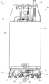
- the drilling tool 10 is designed as a drilling bucket with a base body 12 which includes a housing-like, drum-shaped drill box 14 .
- a connecting device 16 for the detachable connection of a drill rod and an unlocking device 17 are arranged in a basically known manner.
- the unlocking device 17 serves to unlock and open a folding floor 24 which is mounted on the underside of the drum-shaped drill box 14 so that it can be folded open via a folding joint 26 .
- the mechanism for unlocking and locking the folding floor 24 is known in principle and is not explained in more detail below.
- a plate-shaped rotary member 40 is mounted on the folding floor 24 on the underside of the base body 12 so that it can rotate about a central drilling axis between a first rotary position and a second rotary position.
- the plate-shaped rotary member 40 is in the first rotary position, with the adjustable removal elements 30 being in their radially retracted retracted position, as is particularly evident in FIGS figures 2 and 3 is shown.
- the removal elements 30 designed as cutting teeth are retracted radially inwards in such a way that they do not protrude radially with respect to the outer circumference of the drum-shaped drill box 14 .
- the removal elements 30 are arranged on two opposite swivel arms 50 in the drilling tool 10 .
- the swivel arms 50 are pivotably mounted at their respective radially inner end on a respective swivel bolt 28 .
- the pivot pin 28 is fixedly attached to the hinged floor 24 and extends parallel with a certain radial offset to the central drilling axis.
- the swivel arms 50 each have a connecting link hole 52 which extends approximately in the radial direction and which in the exemplary embodiment shown is essentially designed as an elongated hole.
- two removal elements 30 angled relative to one another are releasably attached.
- the slat-shaped swing arms 50 have a reinforced outer portion and a thinned inner portion, with a recess 58 formed at the inner portion of the swing arm 50. As shown in FIG. The recess 58 allows the excavated soil material to pass underneath the swivel arm 50.
- the plate-shaped rotating member 40 which is designed as a rotating floor 42, two removal devices 20 with removal teeth 22 are arranged on a holder 21 each.
- the removal teeth 22 designed as cutting teeth are used to remove existing soil material during drilling.
- a pilot cutting edge 19 for centering the drilling tool 10 during drilling is also arranged in a basically known manner.
- the two pivot arms 50 are each mounted pivotably about pivot bolts 28 which are fixedly attached to the hinged floor 24 and thus to the base body 12 of the drilling tool 10 .
- Two actuating cams 46 designed as bolts 48 are attached to the plate-shaped rotary member 40 for pivoting the pivot arms 50 .
- the bolts 48 engage in the respective associated connecting link hole 52 on the respective swivel arm 50 .
- the plate-shaped rotary member 40 with the removal devices 20 attached thereto is rotated counter to the direction of drilling rotation from the first rotational position figure 3 to a second rotational position according to figure 5 misaligned.
- this second rotational position two receiving openings 25 on the folding floor 24 are released, through which the removed soil material can enter the receiving space inside the drum-shaped drill box 14 .
- the rotary member 40 is rotatably mounted on the folding floor 24 via a central axis of rotation 44 .
- the rotary movement counter to the direction of rotation of the drill also causes the actuating cams 46 embodied as bolts 48 to be adjusted in relation to the swivel arms 50 mounted on the hinged floor 24 in the respective connecting link hole 52 .
- the swivel arms 50 with the removal elements 30 attached thereto are moved out of their radially retracted retracted position according to FIG 3 to its radially extended position according to FIG figure 5 misaligned.
- the removal elements 30 protrude radially outwards in relation to the outer circumference of the drum-shaped drill box 14, so that the removal elements 30 bring about an increase in the drilling diameter.
- the enlargement of the drilling diameter can be set in such a way that soil material is removed below a support tube, not shown, so that the support tube can be tracked into the borehole in a simplified manner.
- the receiving openings 25 are closed at the bottom, so that when the drilling tool 10 is pulled out of the borehole, no soil material can fall out of the receiving space.
- the swivel arms 50 with the removal elements 30 are moved back into their retracted position according to FIG 3 swung back. In this retracted position, the drilling tool 10 can easily be pulled axially through the support tube projecting from above.
Landscapes
- Engineering & Computer Science (AREA)
- Life Sciences & Earth Sciences (AREA)
- Mining & Mineral Resources (AREA)
- Geology (AREA)
- General Life Sciences & Earth Sciences (AREA)
- Environmental & Geological Engineering (AREA)
- Fluid Mechanics (AREA)
- Physics & Mathematics (AREA)
- Geochemistry & Mineralogy (AREA)
- Mechanical Engineering (AREA)
- Paleontology (AREA)
- Civil Engineering (AREA)
- General Engineering & Computer Science (AREA)
- Structural Engineering (AREA)
- Earth Drilling (AREA)
Abstract
Description
- Die Erfindung betrifft ein Bohrwerkzeug zum Erstellen einer Bohrung im Boden, mit einem drehbar antreibbaren Grundkörper, einer Abtragseinrichtung an einem unteren Ende der Grundkörpers zum Abtragen von Bodenmaterial und mindestens einem verstellbaren Abtragselement, welches zwischen einer radial innenliegenden Rückzugsposition und einer radial außenliegenden Erweiterungsposition verstellbar ist, in welcher das Abtragselement radial nach außen gegenüber dem Grundkörper zum Erweitern eines Bohrungsdurchmessers vorsteht, gemäß dem Oberbegriff des Anspruchs 1.
- Die Erfindung betrifft weiterhin ein Verfahren zum Erstellen einer Bohrung im Boden gemäß dem Oberbegriff des Anspruchs 12.
- Derartige Bohrwerkzeuge werden typischerweise für das Erstellen von Gründungspfählen im Boden eingesetzt. Zum Abstützen des Bodens beim Bohren wird häufig zusammen mit dem Bohrwerkzeug ein Stützrohr eingebracht, welches einen etwas größeren Durchmesser als das darin geführte Bohrwerkzeug aufweist. Zum Abtragen von Bodenmaterial unmittelbar durch das Stützrohr kann dieses an seinem unteren Ende mit einem sogenannten Schneidschuh mit Abtragselementen versehen sein. Diese können abhängig von der vorgesehenen Bohrtiefe einem erheblichen Verschleiß ausgesetzt sein. Anders als ein Bohrwerkzeug kann das Stützrohr während des laufenden Verfahrens grundsätzlich nicht oder kaum wieder aus dem Bohrloch rückgezogen werden, da ansonsten das Bohrloch seine notwendige Abstützung für den weiteren Bohrvorgang verlieren würde.
- Es ist weiterhin bekannt, bei einem gewissen Vorauseilen des Bohrwerkzeuges gegenüber dem nachfolgenden Stützrohr an dem Bohrwerkzeug radial verstellbare Abtragselemente vorzuzusehen. Die radialen Abtragselemente können in einen Bereich unterhalb des Stützrohres ausgefahren werden, so dass das Bodenmaterial unmittelbar unterhalb des Stützrohres abgetragen wird. Hierdurch werden ein Verschleiß des Stützrohres erheblich vermindert und ein erleichtertes Einbringen des Stützrohres in den Boden ermöglicht. Zum Rückziehen des Bohrwerkzeuges aus dem Stützrohr kann über eine Verstelleinrichtung das radial verstellbare Abtragselement wieder aus seiner Erweiterungsposition rückgezogen werden, so dass das Bohrwerkzeug kollisionsfrei aus dem Stützrohr rückziehbar ist.
- Zum Verstellen ist es bekannt, hydraulisch betätigte Stellzylinder am Bohrwerkzeug vorzusehen. Dies ist jedoch mechanisch aufwendig und bedarf zudem einer Drehdurchführung zum Zuführen von Hydraulikfluid von außen an das im Betrieb drehende Bohrwerkzeug. Weiterhin sind Verstelleinrichtungen bekannt, bei welchen eine axiale Stellbewegung am Bohrwerkzeug, etwa durch das axiale Bohrgestänge, in eine radiale Verstellbewegung umgesetzt wird. Das Umsetzen einer Axialbewegung in eine Radialbewegung ist mechanisch aufwendig und benötigt in dem begrenzten Bauraum eines Bohrwerkzeuges entsprechend Platz.
- Der Erfindung liegt die Aufgabe zugrunde, ein Bohrwerkzeug und ein Verfahren zum Erstellen einer Bohrung im Boden anzugeben, mit welchen in einfacher und zuverlässiger Weise eine radiale Durchmesserveränderung erreichbar sind.
- Die Aufgabe wird zum einen durch ein Bohrwerkzeug mit den Merkmalen des Anspruchs 1 und zum anderen durch ein Verfahren mit den Merkmalen des Anspruchs 12 gelöst. Bevorzugte Ausführungsformen der Erfindung sind in den abhängigen Ansprüchen angegeben.
- Das erfindungsgemäße Bohrwerkzeug ist dadurch gekennzeichnet, dass zum Verstellen des Abtragselementes ein Verstellmechanismus mit einem Drehglied vorgesehen ist, welches an dem Grundkörper drehbar um die Bohrachse zwischen einer ersten Drehposition und zweiten Drehposition ist, dass das mindestens eine Abtragselement an einem Schwenkarm angeordnet ist, welcher gegenüber dem Grundkörper zwischen einer ersten Schwenkposition, bei welcher sich das mindestens eine Abtragselement in seiner Rückzugsposition befindet, und einer zweiten Schwenkposition verschwenkbar ist, in welcher sich das mindestens eine Abtragselement in seiner Erweiterungsposition befindet, und dass an dem Drehglied und/oder an dem mindestens einen Schwenkarm ein Betätigungsnocken vorgesehen ist, durch welchen eine Drehbewegung des Drehgliedes in eine Schwenkbewegung des mindestens einen Schwenkarms umsetzbar ist.
- Das Bohrwerkzeug kann grundsätzlich beliebig ausgebildet sein, etwa als eine Endlosschnecke, eine Bohrschnecke oder als ein Kastenbohrer. Ein erster Aspekt der Erfindung besteht dabei darin, dass das mindestens eine radial verstellbare Abtragselement nicht einfach in einer radialen Richtung linear verstellbar ist, sondern an einem Schwenkarm verschwenkbar zwischen einer Rückzugsposition und einer Erweiterungsposition gelagert ist.
- Gemäß einem weiteren Aspekt der Erfindung weist der Verstellmechanismus zum Verstellen des Abtragselementes ein Drehglied auf, welches zwischen einer ersten Drehposition und einer zweiten Drehposition verdrehbar ist. Das Drehglied und der mindestens eine Schwenkarm sind dabei über einen Betätigungsnocken miteinander gekoppelt, so dass eine Zwangssteuerung gegeben ist. Bei einer definierten Drehposition des Drehgliedes kann so eine definierte Schwenkposition des Schwenkarms erreicht werden.
- Das Drehglied ist dabei drehbar um die Bohrachse des Bohrwerkzeuges gelagert, so dass abhängig von der Drehrichtung des Bohrwerkzeuges eine Verdrehung des Drehgliedes und damit ein Verschwenken des Schwenkarmes bewirkt wird. Somit wird eine Zwangssteuerung erreicht, bei welcher definiert das mindestens eine Abtragselement an dem Schwenkarm zwischen der Rückzugsposition und der radialen Erweiterungsposition bewegt wird. Insgesamt kann so ein einfacher und kompakter Verstellmechanismus und damit ein einfach aufgebautes Bohrwerkzeug mit der Möglichkeit zur radialen Durchmessererweiterung verwirklicht werden.
- Grundsätzlich kann die Betätigungsnocke in einer beliebigen Weise ausgebildet sein. Eine besonders robuste und einfach herzustellende Ausführungsvariante besteht nach der Erfindung darin, dass die mindestens eine Betätigungsnocke als ein Bolzen ausgebildet ist. Vorzugsweise erstreckt sich der Bolzen in Längsrichtung des Bohrwerkzeuges, also in Bohrrichtung und parallel zur Bohrachse.
- Der Bolzen kann dabei grundsätzlich an dem Schwenkarm angebracht sein und in eine entsprechende Kulissenführung am Drehglied eingreifen. Bevorzugt ist es nach einer Weiterbildung der Erfindung, dass die als Bolzen ausgebildete Betätigungsnocke an dem Drehglied angebracht ist und dass an dem mindestens einen Schwenkarm ein Kulissenloch, insbesondere ein Langloch, ausgebildet ist, in welches der Bolzen eingreift. Dies erlaubt einen besonders robusten und einfachen Aufbau des Bohrwerkzeuges.
- Eine weitere robuste Ausgestaltung wird nach der Erfindung dadurch erzielt, dass an dem Grundkörper mindestens ein Schwenkbolzen angeordnet ist, an welchem der mindestens eine Schwenkarm schwenkbar gelagert ist. Der Schwenkbolzen kann dabei am Grundkörper feststehend sein, während der Schwenkarm über ein einfaches Gleitlager an dem Schwenkbolzen schwenkbar gelagert ist. Grundsätzlich kann jedoch der Schwenkbolzen auch an dem Schwenkarm fest angebracht sein und in ein entsprechendes hülsenförmiges Schwenklager am Grundkörper eingreifen.
- Eine besonders gute Funktionsfähigkeit und Kraftverteilung wird nach einer weiteren Ausführungsvariante der Erfindung dadurch erzielt, dass zwei Schwenkarme mit mindestens einem Abtragselement in einer gegenüberliegenden Anordnung am unteren Ende des Grundkörpers vorgesehen sind. Die Schwenkarme sind dabei etwa um 180° zueinander um die Bohrachse versetzt angeordnet. Diese im Wesentlichen symmetrische Ausgestaltung ermöglicht eine gleichmäßige Kraftverteilung in Bezug auf den Umfang.
- Besonders zweckmäßig ist es nach einer Weiterbildung der Erfindung, dass der Grundkörper als ein trommelförmiger Bohrkasten mit mindestens einer unteren Aufnahmeöffnung ausgebildet ist und dass das Drehglied als ein Drehboden zum Öffnen und Schließen der mindestens einen Aufnahmeöffnung ausgebildet ist. Das Bohrwerkzeug ist somit als ein Kastenbohrer oder Bohreimer mit einem trommelförmigen Grundkörper ausgebildet. Derartige Bohreimer weisen zum Öffnen und Schließen der mindestens einen Aufnahmeöffnung einen Drehboden auf, welcher um die Bohrachse drehbar gelagert ist. Ein solcher Drehboden kann als ein Drehglied für die Erfindung verwendet werden.
- Dabei ist es nach einer bevorzugten Ausführungsform der Erfindung vorteilhaft, dass die Abtragseinrichtung an dem Drehboden angeordnet ist. Die Abtragseinrichtung kann dabei insbesondere durch Schneidzähne gebildet sein, welche etwa linear in einer radialen Richtung entlang des Drehbodens an der Aufnahmeöffnung angeordnet sind.
- Für ein schnelles Entleeren eines derartigen Kastenbohrers oder Bohreimers ist es nach einer weiteren Ausführungsvariante der Erfindung bevorzugt, dass an einem unteren Bereich des trommelförmigen Bohrkastens ein Klappboden aufklappbar angeordnet ist, an welchem der Drehboden drehbar gelagert ist. Der Klappboden mit dem Drehboden kann so um eine im Wesentlichen horizontale Schwenk- oder Klappachse, welche etwa senkrecht zur Bohrachse gerichtet ist, aufgeklappt werden. Auf diese Weise kann die Unterseite des Bohrkastens geöffnet werden, so dass darin befindliches Bodenmaterial einfach entleert werden kann.
- Eine besonders kompakte Bauform des Bohrwerkzeuges wird nach einer Weiterbildung der Erfindung dadurch erzielt, dass der mindestens eine Schwenkbolzen an dem Grundkörper als ein Anschlag zum Begrenzen der Drehbewegung des Drehbodens ausgebildet ist. Der Drehboden kann so mit einem begrenzten Dreh- oder Verstellbereich ausgebildet sein, so dass dieser exakt die mindestens einen Aufnahmeöffnung freigibt oder abdeckt.
- Ein zweckmäßiger Betrieb des erfindungsgemäßen Bohrwerkzeugs wird weiter dadurch erreicht, dass an dem mindestens einen Schwenkarm eine Ausnehmung zum Bilden eines Durchgangsbereiches für abgetragenes Bodenmaterial ausgebildet ist. Insbesondere kann der Schwenkarm in Richtung der Bohrachse einen Bereich mit verringerter Wandstärke aufweisen, so dass ein Durchgangsbereich für abgetragenes Bodenmaterial in einer horizontalen Richtung gegeben ist. Dies vereinfacht zudem ein Verschwenken des Schwenkarms.
- Eine weitere vorteilhafte Ausgestaltungsform der Erfindung besteht darin, dass sich das mindestens eine Abtragselement in der Rückzugsposition befindet, wenn der Drehboden die mindestens einen Aufnahmeöffnung am Bohrkasten verschließt, und dass sich das mindestens einen Abtragselement in der radial vorstehenden Erweiterungsposition befindet, wenn der Drehboden die Aufnahmeöffnung freigibt.
- Bei einem Bohrbetrieb mit geöffneter Aufnahmeöffnung kann so bei einem Voreilen des Bohrwerkzeuges eine Durchmessererweiterung unterhalb eines Stützrohres erzielt werden. Somit kann in diesem Zustand auch anstehendes Bodenmaterial unter einem radial äußeren Stützrohr zuverlässig abgetragen werden. Hierdurch wird das Einbringen des Stützrohres bei einem verrohrten Bohren erheblich vereinfacht.
- Für ein Rückziehen des Bohrwerkzeuges aus dem Bohrloch für einen Entleervorgang wird die Aufnahmeöffnung durch Verdrehen des Drehbodens geschlossen. Dabei wird durch die vorgesehene Zwangssteuerung das mindestens eine Abtragselement von der radial äußeren Erweiterungsposition in die radial innere Rückzugsposition rückgestellt. Auf diese Weise kann das Bohrwerkzeug zuverlässig und ohne Gefahr einer Kollision des Abtragselementes mit dem Stützrohr rückgezogen werden.
- Die Erfindung umfasst weiterhin ein Verfahren zum Herstellen einer Bohrung im Boden, wobei das zuvor beschriebene erfindungsgemäße Bohrwerkzeug eingesetzt wird. Mit dem erfindungsgemäßen Verfahren können die zuvor beschriebenen Vorteile beim Erstellen einer Bohrung im Boden erzielt werden.
- Eine besonders bevorzugte Verfahrensvariante besteht erfindungsgemäß darin, dass durch ein Verdrehen des Drehgliedes des Bohrwerkzeuges beim Bohren das mindestens eine Abtragselement radial verstellt wird, wobei sich ein Bohrungsdurchmesser verändert. So kann durch radiales Ausfahren des mindestens einen Abtragselementes eine radiale Bohrungserweiterung vorgenommen werden. In umgekehrter Weise kann bei einem radialen Rückziehen des mindestens einen Abtragselementes in eine Rückzugsposition ein Zustand des Bohrwerkzeuges erreicht werden, in welchem das Bohrwerkzeug problemlos durch das Stützrohr rückgezogen werden kann.
- Die Erfindung wird nachfolgend anhand eines bevorzugten Ausführungsbeispieles weiter beschrieben, welches in den Zeichnungen dargestellt ist. In den Zeichnungen zeigen:
- Fig. 1
- eine erste Seitenansicht eines erfindungsgemäßen Bohrwerkzeuges;
- Fig. 2
- eine zweite Seitenansicht, die um 90° zu der Seitenansicht von
Fig. 1 gedreht ist, zu dem Bohrwerkzeug nachFig. 1 mit Abtragselementen in Rückzugsposition; - Fig. 3
- eine Ansicht von unten des Bohrwerkzeuges nach den
Figuren 1 und2 mit Abtragselementen in Rückzugsposition; - Fig. 4
- eine Seitenansicht des Bohrwerkzeuges entsprechend
Fig. 2 mit radial ausgefahrenen Abtragselementen; - Fig. 5
- eine Ansicht des Bohrwerkzeuges von
Fig. 4 von unten; und - Fig. 6
- eine perspektivische Explosionsdarstellung des Bohrwerkzeuges nach den
Figuren 1 bis 5 . - Nachfolgend wird ein erfindungsgemäßes Bohrwerkzeug 10 im Zustand mit Abtragselementen 30 in Rückzugsposition in Zusammenhang mit den
Figuren 1 bis 3 erläutert. Das Bohrwerkzeug 10 ist in dem dargestellten Ausführungsbeispiel als ein Bohreimer mit einem Grundkörper 12 ausgebildet, welcher einen gehäuseartigen trommelförmigen Bohrkasten 14 umfasst. In einem Deckbereich 15 des Grundkörpers 12 sind in grundsätzlich bekannter Weise eine Verbindungseinrichtung 16 zum lösbaren Anbinden eines Bohrgestänges und eine Entriegelungseinrichtung 17 angeordnet. Die Entriegelungseinrichtung 17 dient zum Entriegeln und Öffnen eines Klappbodens 24, welcher über ein Klappgelenk 26 aufklappbar an der Unterseite des trommelförmigen Bohrkastens 14 gelagert ist. - Die Mechanik zum Entriegeln und Verriegeln des Klappbodens 24 ist grundsätzlich bekannt und wird im Folgenden nicht näher erläutert.
- An dem Klappboden 24 an der Unterseite des Grundkörpers 12 ist ein plattenförmiges Drehglied 40 drehbar um eine mittige Bohrachse zwischen einer ersten Drehposition und einer zweiten Drehposition gelagert. In den
Figuren 1 bis 3 befindet sich das plattenförmige Drehglied 40 in der ersten Drehposition, wobei die verstellbaren Abtragselemente 30 sich in ihrer radial eingezogenen Rückzugsposition befinden, wie insbesondere deutlich in denFiguren 2 und3 dargestellt ist. - In der Rückzugsposition sind die als Schneidzähne ausgebildeten Abtragselemente 30 radial so nach innen eingefahren, dass diese nicht radial gegenüber dem Außenumfang des trommelförmigen Bohrkastens 14 vorstehen.
- Zum Verstellen der Abtragselemente 30 sind diese bei dem Bohrwerkzeug 10 an zwei gegenüberliegenden Schwenkarmen 50 angeordnet. Die Schwenkarme 50 sind dabei an ihrem jeweils radial innenliegenden Ende an jeweils einem Schwenkbolzen 28 schwenkbar gelagert. Der Schwenkbolzen 28 ist fest an dem Klappboden 24 angebracht und erstreckt sich parallel mit einem gewissen Radialversatz zur mittigen Bohrachse. Weiterhin weisen die Schwenkarme 50 jeweils ein sich etwa in radialer Richtung erstreckendes Kulissenloch 52 auf, welches im dargestellten Ausführungsbeispiel im Wesentlichen als ein Langloch ausgebildet ist. Am radial äußeren Ende der Schwenkarme 50 sind jeweils zwei zueinander angewinkelte Abtragselemente 30 lösbar angebracht.
- Die leistenförmigen Schwenkarme 50 weisen einen verstärkten äußeren Bereich und einen verdünnten inneren Bereich auf, wobei eine Ausnehmung 58 am inneren Bereich des Schwenkarmes 50 gebildet ist. Die Ausnehmung 58 erlaubt einen Durchgang von abgetragenem Bodenmaterial unterhalb des Schwenkarmes 50.
- An dem plattenförmigen Drehglied 40, welches als ein Drehboden 42 ausgebildet ist, sind zwei Abtragseinrichtungen 20 mit Abtragszähnen 22 an jeweils einer Halterung 21 angeordnet. Die als Schneidzähne ausgebildeten Abtragszähne 22 dienen zum Abtragen von anstehendem Bodenmaterial beim Bohren. Am unteren Ende des Bohrwerkzeuges 10 ist weiterhin in grundsätzlich bekannter Weise eine Pilotschneide 19 zum Zentrieren des Bohrwerkzeuges 10 beim Bohren angeordnet.
- Die Funktionsweise des Verstellmechanismus zum Verstellen der Abtragselemente 30 wird näher in Zusammenhang mit den
Figuren 4 bis 6 erläutert. Die beiden Schwenkarme 50 sind jeweils schwenkbar um Schwenkbolzen 28 gelagert, welche fest an dem Klappboden 24 und damit an dem Grundkörper 12 des Bohrwerkzeuges 10 angebracht sind. Zum Verschwenken der Schwenkarme 50 sind an dem plattenförmigen Drehglied 40 zwei als Bolzen 48 ausgebildete Betätigungsnocken 46 angebracht. Die Bolzen 48 greifen dabei in das jeweils zugeordnete Kulissenloch 52 an dem jeweiligen Schwenkarm 50 ein. - Wird das Bohrwerkzeug 10 in Bezug auf die
Figuren 3 und5 in eine Bohrdrehrichtung angetrieben, welche entgegengesetzt dem Uhrzeigersinn ist, wird das plattenförmige Drehglied 40 mit den daran angebrachten Abtragseinrichtungen 20 entgegen der Bohrdrehrichtung aus der ersten Drehposition gemäßFigur 3 in eine zweite Drehposition gemäßFigur 5 verstellt. Bei dieser zweiten Drehposition werden zwei Aufnahmeöffnungen 25 am Klappboden 24 freigegeben, durch welche das abgetragene Bodenmaterial in den Aufnahmeraum innerhalb des trommelförmigen Bohrkastens 14 gelangen kann. Das Drehglied 40 ist über eine mittige Drehachse 44 an dem Klappboden 24 drehbar gelagert. - Durch die Drehbewegung entgegen der Bohrdrehrichtung werden auch die als Bolzen 48 ausgebildeten Betätigungsnocken 46 gegenüber den am Klappboden 24 gelagerten Schwenkarmen 50 in dem jeweiligen Kulissenloch 52 verstellt. Durch diese zwangsgesteuerte Relativbewegung werden die Schwenkarme 50 mit den daran angebrachten Abtragselementen 30 aus ihrer radial eingefahrenen Rückzugsposition gemäß
Fig. 3 in ihre radial ausgefahrene Erweiterungsposition gemäßFig. 5 verstellt. In dieser Erweiterungsposition ragen die Abtragselemente 30 radial nach außen gegenüber dem Außenumfang des trommelförmigen Bohrkastens 14 vor, so dass die Abtragselemente 30 eine Vergrößerung des Bohrdurchmessers bewirken. Die Vergrößerung des Bohrdurchmessers kann dabei so eingestellt sein, dass Bodenmaterial unterhalb eines nicht dargestellten Stützrohres abgetragen wird, so dass in vereinfachter Weise das Stützrohr in das Bohrloch nachgeführt werden kann. - Bei Beendigung eines Bohrschrittes, etwa bei einer ausreichenden Füllung des Aufnahmeraumes in dem Bohrkasten 14 durch abgetragenes Bodenmaterial, kann durch eine kurzzeitige Rückdrehung des Bohrwerkzeuges 10 entgegen der Bohrrichtung, also in Bezug auf die
Figuren 3 und5 im Uhrzeigersinn, das als Drehboden 42 ausgebildete Drehglied 40 wieder in die erste Drehposition gemäßFig. 3 rückgedreht werden. Hierbei werden die Aufnahmeöffnungen 25 nach unten verschlossen, so dass beim Ziehen des Bohrwerkzeuges 10 aus dem Bohrloch kein Bodenmaterial aus dem Aufnahmeraum nach unten fallen kann. - Gleichzeitig mit dem Schließen der Aufnahmeöffnungen 25 werden durch die Rückdrehung des Drehbodens 42 in die erste Drehposition die Schwenkarme 50 mit den Abtragselementen 30 wieder in ihre Rückzugsposition gemäß
Fig. 3 rückgeschwenkt. In dieser eingezogenen Position kann das Bohrwerkzeug 10 problemlos axial durch das von oben anstehende Stützrohr gezogen werden.
Claims (13)
- Bohrwerkzeug zum Erstellen einer Bohrung im Boden, mit- einem drehbar antreibbaren Grundkörper (12),- einer Abtragseinrichtung (20) an einem unteren Ende des Grundkörpers (12) zum Abtragen von Bodenmaterial und- mindestens einem verstellbaren Abtragselement (30), welches zwischen einer radial innenliegenden Rückzugsposition und einer radial außenliegenden Erweiterungsposition verstellbar ist, in welcher das Abtragselement (30) radial nach außen gegenüber dem Grundkörper (12) zum Erweitern eines Bohrungsdurchmessers vorsteht,dadurch gekennzeichnet,- dass zum Verstellen des Abtragselementes (30) ein Verstellmechanismus mit einem Drehglied (40) vorgesehen ist, welches an dem Grundkörper (12) drehbar um die Bohrachse zwischen einer ersten Drehposition und einer zweiten Drehposition ist,- dass das mindestens eine Abtragselement (30) an einem Schwenkarm (50) angeordnet ist, welcher gegenüber dem Grundkörper (12) zwischen einer ersten Schwenkposition, bei welcher sich das mindestens eine Abtragselement (30) in seiner Rückzugsposition befindet, und einer zweiten Schwenkposition verschwenkbar ist, in welcher sich das mindestens eine Abtragselement (30) in seiner Erweiterungsposition befindet, und- dass an dem Drehglied (40) und/oder an dem mindestens einen Schwenkarm (50) ein Betätigungsnocken (46) vorgesehen ist, durch welchen eine Drehbewegung des Drehgliedes (40) in eine Schwenkbewegung des mindestens einen Schwenkarms (50) umsetzbar ist.
- Bohrwerkzeug nach Anspruch 1,
dadurch gekennzeichnet,
dass der mindestens eine Betätigungsnocken (46) als ein Bolzen (48) ausgebildet ist. - Bohrwerkzeug nach Anspruch 2,
dadurch gekennzeichnet,
dass der als Bolzen (48) ausgebildete Betätigungsnocken (46) an dem Drehglied (40) angebracht ist und
dass an dem mindestens einen Schwenkarm (50) ein Kulissenloch (52), insbesondere ein Langloch, ausgebildet ist, in welches der Bolzen (48) eingreift. - Bohrwerkzeug nach einem der Ansprüche 1 bis 3,
dadurch gekennzeichnet,
dass an dem Grundkörper (12) mindestens ein Schwenkbolzen (28) angeordnet ist, an welchem der mindestens eine Schwenkarm (50) schwenkbar gelagert ist. - Bohrwerkzeug nach einem der Ansprüche 1 bis 4,
dadurch gekennzeichnet,
dass zwei Schwenkarme (50) mit mindestens einem Abtragselement (30) in einer gegenüberliegenden Anordnung am unteren Ende des Grundkörpers (12) vorgesehen sind. - Bohrwerkzeug nach einem der Ansprüche 1 bis 5,
dadurch gekennzeichnet,
dass der Grundkörper (12) einen trommelförmigen Bohrkasten (14) mit mindestens einer unteren Aufnahmeöffnung (25) aufweist und
dass das Drehglied (40) als ein Drehboden (42) zum Öffnen und Schließen der mindestens einen Aufnahmeöffnung (25) ausgebildet ist. - Bohrwerkzeug nach Anspruch 6,
dadurch gekennzeichnet,
dass die Abtragseinrichtung (30) an dem Drehboden (42) angeordnet ist. - Bohrwerkzeug nach Anspruch 6 oder 7,
dadurch gekennzeichnet,
dass an einem unteren Bereich des trommelförmigen Bohrkastens (14) ein Klappboden (24) aufklappbar angeordnet ist, an welchem der Drehboden (42) drehbar gelagert ist. - Bohrwerkzeug nach einem der Ansprüche 6 bis 8,
dadurch gekennzeichnet,
dass der mindestens eine Schwenkbolzen (28) an dem Grundkörper (12) als ein Anschlag zum Begrenzen der Drehbewegung des Drehbodens (42) ausgebildet ist. - Bohrwerkzeug nach einem der Ansprüche 1 bis 9,
dadurch gekennzeichnet,
dass an dem mindestens einen Schwenkarm (50) eine Ausnehmung (58) zum Bilden eines Durchgangsbereiches für abgetragenes Bodenmaterial ausgebildet ist. - Bohrwerkzeug nach einem der Ansprüche 6 bis 10,
dadurch gekennzeichnet,
dass sich das mindestens eine Abtragselement (30) in der Rückzugsposition befindet, wenn der Drehboden (42) die mindestens eine Aufnahmeöffnung (25) am Bohrkasten (14) verschließt, und
dass sich das mindestens eine Abtragselement (30) in der radial vorstehenden Erwiderungsposition befindet, wenn der Drehboden (42) die Aufnahmeöffnung (25) freigibt. - Verfahren zum Herstellen einer Bohrung im Boden,
dadurch gekennzeichnet,
dass ein Bohrwerkzeug (10) nach einem der Ansprüche 1 bis 11 eingesetzt wird. - Verfahren nach Anspruch 12,
dadurch gekennzeichnet,
dass durch ein Verdrehen des Drehgliedes (40) des Bohrwerkzeuges (10) beim Bohren das mindestens eine Abtragselement (30) radial verstellt wird, wobei sich ein Bohrungsdurchmesser verändert.
Priority Applications (6)
| Application Number | Priority Date | Filing Date | Title |
|---|---|---|---|
| EP21214859.7A EP4198253B1 (de) | 2021-12-15 | 2021-12-15 | Bohrwerkzeug und verfahren zum erstellen einer bohrung im boden |
| US18/719,587 US12359511B2 (en) | 2021-12-15 | 2022-12-02 | Drilling tool and method for producing a bore in the ground |
| CN202280090985.4A CN118922613A (zh) | 2021-12-15 | 2022-12-02 | 用于在土地中构建钻孔的钻孔工具和方法 |
| CA3241334A CA3241334A1 (en) | 2021-12-15 | 2022-12-02 | Drilling tool and method for producing a bore in the ground |
| PCT/EP2022/084183 WO2023110450A1 (de) | 2021-12-15 | 2022-12-02 | Bohrwerkzeug und verfahren zum erstellen einer bohrung im boden |
| AU2022409132A AU2022409132B2 (en) | 2021-12-15 | 2022-12-02 | Drilling tool and method for producing a bore in the ground |
Applications Claiming Priority (1)
| Application Number | Priority Date | Filing Date | Title |
|---|---|---|---|
| EP21214859.7A EP4198253B1 (de) | 2021-12-15 | 2021-12-15 | Bohrwerkzeug und verfahren zum erstellen einer bohrung im boden |
Publications (3)
| Publication Number | Publication Date |
|---|---|
| EP4198253A1 true EP4198253A1 (de) | 2023-06-21 |
| EP4198253C0 EP4198253C0 (de) | 2024-04-17 |
| EP4198253B1 EP4198253B1 (de) | 2024-04-17 |
Family
ID=79024186
Family Applications (1)
| Application Number | Title | Priority Date | Filing Date |
|---|---|---|---|
| EP21214859.7A Active EP4198253B1 (de) | 2021-12-15 | 2021-12-15 | Bohrwerkzeug und verfahren zum erstellen einer bohrung im boden |
Country Status (6)
| Country | Link |
|---|---|
| US (1) | US12359511B2 (de) |
| EP (1) | EP4198253B1 (de) |
| CN (1) | CN118922613A (de) |
| AU (1) | AU2022409132B2 (de) |
| CA (1) | CA3241334A1 (de) |
| WO (1) | WO2023110450A1 (de) |
Citations (1)
| Publication number | Priority date | Publication date | Assignee | Title |
|---|---|---|---|---|
| CN113236131A (zh) * | 2021-06-28 | 2021-08-10 | 湖南省大盛基础工程有限公司 | 扩底钻头 |
Family Cites Families (12)
| Publication number | Priority date | Publication date | Assignee | Title |
|---|---|---|---|---|
| US2873950A (en) * | 1954-01-25 | 1959-02-17 | Charles W Kandle | Spring loaded earth drill |
| DE2709030C2 (de) * | 1977-03-02 | 1985-05-15 | Stahl- Und Apparatebau Hans Leffer Gmbh, 6602 Dudweiler | Drehbohrkrone mit Schwenkflügeln |
| US5013191A (en) * | 1989-01-09 | 1991-05-07 | Katsumi Kitanaka | Cast-in-place piling method and apparatus |
| JP3399514B2 (ja) * | 1999-08-12 | 2003-04-21 | 大成建設株式会社 | 掘削推進機の推進方向修正装置 |
| US7367412B2 (en) * | 2006-04-26 | 2008-05-06 | Barbera Anthony R | Collapsible rock head |
| IT1394002B1 (it) * | 2009-04-21 | 2012-05-17 | Soilmec Spa | Attrezzatura di scavo e costipazione per la costruzione di pali a vite. |
| US8567530B2 (en) * | 2010-02-26 | 2013-10-29 | James S. Barbera | Collapsible rock head and associated structure |
| EP2770156B1 (de) * | 2013-02-26 | 2018-10-10 | BAUER Spezialtiefbau GmbH | Bohrwerkzeug und Verfahren zum Erdbohren |
| US10145193B2 (en) * | 2013-03-18 | 2018-12-04 | Spinoff Drilling Buckets | Axially separating drill bucket |
| FI20176174A1 (fi) * | 2017-12-27 | 2019-06-28 | Tri Mach Oy | Porakruunu |
| CN111911078B (zh) * | 2020-09-03 | 2022-02-11 | 长沙天和钻具机械有限公司 | 一种扩孔式旋翼钻具 |
| CN113445927B (zh) * | 2021-08-09 | 2024-12-03 | 湖南省大盛基础工程有限公司 | 一种扩底钻头 |
-
2021
- 2021-12-15 EP EP21214859.7A patent/EP4198253B1/de active Active
-
2022
- 2022-12-02 CN CN202280090985.4A patent/CN118922613A/zh active Pending
- 2022-12-02 CA CA3241334A patent/CA3241334A1/en active Pending
- 2022-12-02 AU AU2022409132A patent/AU2022409132B2/en active Active
- 2022-12-02 WO PCT/EP2022/084183 patent/WO2023110450A1/de not_active Ceased
- 2022-12-02 US US18/719,587 patent/US12359511B2/en active Active
Patent Citations (1)
| Publication number | Priority date | Publication date | Assignee | Title |
|---|---|---|---|---|
| CN113236131A (zh) * | 2021-06-28 | 2021-08-10 | 湖南省大盛基础工程有限公司 | 扩底钻头 |
Also Published As
| Publication number | Publication date |
|---|---|
| AU2022409132A1 (en) | 2024-06-13 |
| US12359511B2 (en) | 2025-07-15 |
| WO2023110450A1 (de) | 2023-06-22 |
| US20250043636A1 (en) | 2025-02-06 |
| AU2022409132B2 (en) | 2025-04-24 |
| CA3241334A1 (en) | 2023-06-22 |
| EP4198253C0 (de) | 2024-04-17 |
| EP4198253B1 (de) | 2024-04-17 |
| CN118922613A (zh) | 2024-11-08 |
Similar Documents
| Publication | Publication Date | Title |
|---|---|---|
| DE60133554T2 (de) | Bohrmeissel | |
| DE2849022C2 (de) | Vorrichtung zum Ausheben von Erdlöchern | |
| DE69004812T2 (de) | Verfahren und Vorrichtung zur Herstellung von Pfählen aus Ortbeton. | |
| DE69002517T2 (de) | Bohrspülungseinrichtung für Bohrwerkzeuge. | |
| EP2770156B1 (de) | Bohrwerkzeug und Verfahren zum Erdbohren | |
| DE3014990A1 (de) | Erdbohrgeraet | |
| CH626685A5 (de) | ||
| EP0065284B1 (de) | Räumvorrichtung | |
| EP1640507A1 (de) | Pfahlbohrwerkzeug | |
| EP2927417B1 (de) | Sich öffnende dreh-schlagbohrkrone, insbesondere zum überlagerungsbohren | |
| EP4497908B1 (de) | Bohrkopf und diesen umfassendes bohrsystem | |
| EP4101987B1 (de) | Bohrwerkzeug und verfahren zum erstellen einer bohrung im boden | |
| EP4006298B1 (de) | Bohrvorrichtung | |
| EP4198253B1 (de) | Bohrwerkzeug und verfahren zum erstellen einer bohrung im boden | |
| EP3951128B1 (de) | Vorrichtung zum räumen eines wendelzwischenraumes einer bohrschnecke und verfahren zum erstellen einer bohrung | |
| DE4209854C1 (en) | Stripper for earth auger for excavator - incorporates spring blade between turns of spiral, moving axially as spiral rotates | |
| DE2657751C2 (de) | Überlagerungsbohrgestänge | |
| AT395340B (de) | Drehbohrvorrichtung zum erweitern von vertikalen bohrungen | |
| DE2530531A1 (de) | Drehbohrwerkzeug fuer erdbohrmaschinen | |
| EP1359258B1 (de) | Pfahlfuss-Schneidvorrichtung | |
| EP2236733A1 (de) | Antriebseinheit für ein Bohr- oder Baugerät | |
| EP3392449B1 (de) | Bohrvorrichtung und bohrverfahren zum herstellen einer bohrung im boden | |
| EP4491843B1 (de) | Kastenbohrer und verfahren zum erstellen einer bohrung im boden | |
| EP3190257B1 (de) | Bohrvorrichtung und verfahren zum herstellen eines bohrpfahls im boden | |
| DE3215575A1 (de) | Grosslochbohrvorrichtung |
Legal Events
| Date | Code | Title | Description |
|---|---|---|---|
| PUAI | Public reference made under article 153(3) epc to a published international application that has entered the european phase |
Free format text: ORIGINAL CODE: 0009012 |
|
| STAA | Information on the status of an ep patent application or granted ep patent |
Free format text: STATUS: THE APPLICATION HAS BEEN PUBLISHED |
|
| AK | Designated contracting states |
Kind code of ref document: A1 Designated state(s): AL AT BE BG CH CY CZ DE DK EE ES FI FR GB GR HR HU IE IS IT LI LT LU LV MC MK MT NL NO PL PT RO RS SE SI SK SM TR |
|
| STAA | Information on the status of an ep patent application or granted ep patent |
Free format text: STATUS: REQUEST FOR EXAMINATION WAS MADE |
|
| 17P | Request for examination filed |
Effective date: 20230628 |
|
| RBV | Designated contracting states (corrected) |
Designated state(s): AL AT BE BG CH CY CZ DE DK EE ES FI FR GB GR HR HU IE IS IT LI LT LU LV MC MK MT NL NO PL PT RO RS SE SI SK SM TR |
|
| STAA | Information on the status of an ep patent application or granted ep patent |
Free format text: STATUS: EXAMINATION IS IN PROGRESS |
|
| 17Q | First examination report despatched |
Effective date: 20230804 |
|
| GRAP | Despatch of communication of intention to grant a patent |
Free format text: ORIGINAL CODE: EPIDOSNIGR1 |
|
| STAA | Information on the status of an ep patent application or granted ep patent |
Free format text: STATUS: GRANT OF PATENT IS INTENDED |
|
| RIC1 | Information provided on ipc code assigned before grant |
Ipc: E02D 7/22 20060101ALI20231120BHEP Ipc: E02D 5/44 20060101ALI20231120BHEP Ipc: E21B 27/00 20060101ALI20231120BHEP Ipc: E21B 7/00 20060101ALI20231120BHEP Ipc: E21B 7/20 20060101ALI20231120BHEP Ipc: E21B 10/32 20060101AFI20231120BHEP |
|
| INTG | Intention to grant announced |
Effective date: 20231206 |
|
| GRAS | Grant fee paid |
Free format text: ORIGINAL CODE: EPIDOSNIGR3 |
|
| GRAA | (expected) grant |
Free format text: ORIGINAL CODE: 0009210 |
|
| STAA | Information on the status of an ep patent application or granted ep patent |
Free format text: STATUS: THE PATENT HAS BEEN GRANTED |
|
| AK | Designated contracting states |
Kind code of ref document: B1 Designated state(s): AL AT BE BG CH CY CZ DE DK EE ES FI FR GB GR HR HU IE IS IT LI LT LU LV MC MK MT NL NO PL PT RO RS SE SI SK SM TR |
|
| REG | Reference to a national code |
Ref country code: GB Ref legal event code: FG4D Free format text: NOT ENGLISH |
|
| REG | Reference to a national code |
Ref country code: CH Ref legal event code: EP |
|
| REG | Reference to a national code |
Ref country code: DE Ref legal event code: R096 Ref document number: 502021003379 Country of ref document: DE |
|
| REG | Reference to a national code |
Ref country code: IE Ref legal event code: FG4D Free format text: LANGUAGE OF EP DOCUMENT: GERMAN |
|
| U01 | Request for unitary effect filed |
Effective date: 20240510 |
|
| U07 | Unitary effect registered |
Designated state(s): AT BE BG DE DK EE FI FR IT LT LU LV MT NL PT SE SI Effective date: 20240522 |
|
| PG25 | Lapsed in a contracting state [announced via postgrant information from national office to epo] |
Ref country code: IS Free format text: LAPSE BECAUSE OF FAILURE TO SUBMIT A TRANSLATION OF THE DESCRIPTION OR TO PAY THE FEE WITHIN THE PRESCRIBED TIME-LIMIT Effective date: 20240817 |
|
| PG25 | Lapsed in a contracting state [announced via postgrant information from national office to epo] |
Ref country code: HR Free format text: LAPSE BECAUSE OF FAILURE TO SUBMIT A TRANSLATION OF THE DESCRIPTION OR TO PAY THE FEE WITHIN THE PRESCRIBED TIME-LIMIT Effective date: 20240417 |
|
| PG25 | Lapsed in a contracting state [announced via postgrant information from national office to epo] |
Ref country code: GR Free format text: LAPSE BECAUSE OF FAILURE TO SUBMIT A TRANSLATION OF THE DESCRIPTION OR TO PAY THE FEE WITHIN THE PRESCRIBED TIME-LIMIT Effective date: 20240718 |
|
| PG25 | Lapsed in a contracting state [announced via postgrant information from national office to epo] |
Ref country code: ES Free format text: LAPSE BECAUSE OF FAILURE TO SUBMIT A TRANSLATION OF THE DESCRIPTION OR TO PAY THE FEE WITHIN THE PRESCRIBED TIME-LIMIT Effective date: 20240417 |
|
| PG25 | Lapsed in a contracting state [announced via postgrant information from national office to epo] |
Ref country code: PL Free format text: LAPSE BECAUSE OF FAILURE TO SUBMIT A TRANSLATION OF THE DESCRIPTION OR TO PAY THE FEE WITHIN THE PRESCRIBED TIME-LIMIT Effective date: 20240417 |
|
| PG25 | Lapsed in a contracting state [announced via postgrant information from national office to epo] |
Ref country code: PL Free format text: LAPSE BECAUSE OF FAILURE TO SUBMIT A TRANSLATION OF THE DESCRIPTION OR TO PAY THE FEE WITHIN THE PRESCRIBED TIME-LIMIT Effective date: 20240417 Ref country code: NO Free format text: LAPSE BECAUSE OF FAILURE TO SUBMIT A TRANSLATION OF THE DESCRIPTION OR TO PAY THE FEE WITHIN THE PRESCRIBED TIME-LIMIT Effective date: 20240717 Ref country code: IS Free format text: LAPSE BECAUSE OF FAILURE TO SUBMIT A TRANSLATION OF THE DESCRIPTION OR TO PAY THE FEE WITHIN THE PRESCRIBED TIME-LIMIT Effective date: 20240817 Ref country code: HR Free format text: LAPSE BECAUSE OF FAILURE TO SUBMIT A TRANSLATION OF THE DESCRIPTION OR TO PAY THE FEE WITHIN THE PRESCRIBED TIME-LIMIT Effective date: 20240417 Ref country code: GR Free format text: LAPSE BECAUSE OF FAILURE TO SUBMIT A TRANSLATION OF THE DESCRIPTION OR TO PAY THE FEE WITHIN THE PRESCRIBED TIME-LIMIT Effective date: 20240718 Ref country code: ES Free format text: LAPSE BECAUSE OF FAILURE TO SUBMIT A TRANSLATION OF THE DESCRIPTION OR TO PAY THE FEE WITHIN THE PRESCRIBED TIME-LIMIT Effective date: 20240417 Ref country code: RS Free format text: LAPSE BECAUSE OF FAILURE TO SUBMIT A TRANSLATION OF THE DESCRIPTION OR TO PAY THE FEE WITHIN THE PRESCRIBED TIME-LIMIT Effective date: 20240717 |
|
| REG | Reference to a national code |
Ref country code: DE Ref legal event code: R097 Ref document number: 502021003379 Country of ref document: DE |
|
| PG25 | Lapsed in a contracting state [announced via postgrant information from national office to epo] |
Ref country code: CZ Free format text: LAPSE BECAUSE OF FAILURE TO SUBMIT A TRANSLATION OF THE DESCRIPTION OR TO PAY THE FEE WITHIN THE PRESCRIBED TIME-LIMIT Effective date: 20240417 |
|
| PG25 | Lapsed in a contracting state [announced via postgrant information from national office to epo] |
Ref country code: SK Free format text: LAPSE BECAUSE OF FAILURE TO SUBMIT A TRANSLATION OF THE DESCRIPTION OR TO PAY THE FEE WITHIN THE PRESCRIBED TIME-LIMIT Effective date: 20240417 Ref country code: RO Free format text: LAPSE BECAUSE OF FAILURE TO SUBMIT A TRANSLATION OF THE DESCRIPTION OR TO PAY THE FEE WITHIN THE PRESCRIBED TIME-LIMIT Effective date: 20240417 |
|
| PG25 | Lapsed in a contracting state [announced via postgrant information from national office to epo] |
Ref country code: SM Free format text: LAPSE BECAUSE OF FAILURE TO SUBMIT A TRANSLATION OF THE DESCRIPTION OR TO PAY THE FEE WITHIN THE PRESCRIBED TIME-LIMIT Effective date: 20240417 |
|
| PG25 | Lapsed in a contracting state [announced via postgrant information from national office to epo] |
Ref country code: SM Free format text: LAPSE BECAUSE OF FAILURE TO SUBMIT A TRANSLATION OF THE DESCRIPTION OR TO PAY THE FEE WITHIN THE PRESCRIBED TIME-LIMIT Effective date: 20240417 Ref country code: SK Free format text: LAPSE BECAUSE OF FAILURE TO SUBMIT A TRANSLATION OF THE DESCRIPTION OR TO PAY THE FEE WITHIN THE PRESCRIBED TIME-LIMIT Effective date: 20240417 Ref country code: RO Free format text: LAPSE BECAUSE OF FAILURE TO SUBMIT A TRANSLATION OF THE DESCRIPTION OR TO PAY THE FEE WITHIN THE PRESCRIBED TIME-LIMIT Effective date: 20240417 Ref country code: CZ Free format text: LAPSE BECAUSE OF FAILURE TO SUBMIT A TRANSLATION OF THE DESCRIPTION OR TO PAY THE FEE WITHIN THE PRESCRIBED TIME-LIMIT Effective date: 20240417 |
|
| U20 | Renewal fee for the european patent with unitary effect paid |
Year of fee payment: 4 Effective date: 20241227 |
|
| PLBE | No opposition filed within time limit |
Free format text: ORIGINAL CODE: 0009261 |
|
| STAA | Information on the status of an ep patent application or granted ep patent |
Free format text: STATUS: NO OPPOSITION FILED WITHIN TIME LIMIT |
|
| 26N | No opposition filed |
Effective date: 20250120 |
|
| PG25 | Lapsed in a contracting state [announced via postgrant information from national office to epo] |
Ref country code: MC Free format text: LAPSE BECAUSE OF FAILURE TO SUBMIT A TRANSLATION OF THE DESCRIPTION OR TO PAY THE FEE WITHIN THE PRESCRIBED TIME-LIMIT Effective date: 20240417 |
|
| PG25 | Lapsed in a contracting state [announced via postgrant information from national office to epo] |
Ref country code: IE Free format text: LAPSE BECAUSE OF NON-PAYMENT OF DUE FEES Effective date: 20241215 |
|
| PGFP | Annual fee paid to national office [announced via postgrant information from national office to epo] |
Ref country code: GB Payment date: 20251229 Year of fee payment: 5 |
|
| PGFP | Annual fee paid to national office [announced via postgrant information from national office to epo] |
Ref country code: TR Payment date: 20251125 Year of fee payment: 5 |
|
| U20 | Renewal fee for the european patent with unitary effect paid |
Year of fee payment: 5 Effective date: 20251216 |
|
| REG | Reference to a national code |
Ref country code: CH Ref legal event code: U11 Free format text: ST27 STATUS EVENT CODE: U-0-0-U10-U11 (AS PROVIDED BY THE NATIONAL OFFICE) Effective date: 20260219 |
|
| PGFP | Annual fee paid to national office [announced via postgrant information from national office to epo] |
Ref country code: CH Payment date: 20260219 Year of fee payment: 5 |
|
| PG25 | Lapsed in a contracting state [announced via postgrant information from national office to epo] |
Ref country code: CY Free format text: LAPSE BECAUSE OF FAILURE TO SUBMIT A TRANSLATION OF THE DESCRIPTION OR TO PAY THE FEE WITHIN THE PRESCRIBED TIME-LIMIT Effective date: 20240417 |
|
| PG25 | Lapsed in a contracting state [announced via postgrant information from national office to epo] |
Ref country code: HU Free format text: LAPSE BECAUSE OF FAILURE TO SUBMIT A TRANSLATION OF THE DESCRIPTION OR TO PAY THE FEE WITHIN THE PRESCRIBED TIME-LIMIT; INVALID AB INITIO Effective date: 20211215 |