EP4197838A1 - Procédé et système d'assistance à un conducteur d'un véhicule routier - Google Patents
Procédé et système d'assistance à un conducteur d'un véhicule routier Download PDFInfo
- Publication number
- EP4197838A1 EP4197838A1 EP21306848.9A EP21306848A EP4197838A1 EP 4197838 A1 EP4197838 A1 EP 4197838A1 EP 21306848 A EP21306848 A EP 21306848A EP 4197838 A1 EP4197838 A1 EP 4197838A1
- Authority
- EP
- European Patent Office
- Prior art keywords
- processing unit
- data processing
- condition
- road vehicle
- driver
- Prior art date
- Legal status (The legal status is an assumption and is not a legal conclusion. Google has not performed a legal analysis and makes no representation as to the accuracy of the status listed.)
- Pending
Links
- 238000000034 method Methods 0.000 title claims abstract description 28
- 230000000007 visual effect Effects 0.000 claims abstract description 32
- 230000001133 acceleration Effects 0.000 claims description 9
- 230000036626 alertness Effects 0.000 claims description 9
- 238000003384 imaging method Methods 0.000 claims description 8
- 230000008859 change Effects 0.000 claims description 5
- 230000004048 modification Effects 0.000 description 24
- 238000012986 modification Methods 0.000 description 24
- 230000008569 process Effects 0.000 description 4
- 230000005043 peripheral vision Effects 0.000 description 3
- 230000001960 triggered effect Effects 0.000 description 3
- 239000004973 liquid crystal related substance Substances 0.000 description 2
- 230000001953 sensory effect Effects 0.000 description 2
- 238000003491 array Methods 0.000 description 1
- 230000004044 response Effects 0.000 description 1
Images


Classifications
-
- B—PERFORMING OPERATIONS; TRANSPORTING
- B60—VEHICLES IN GENERAL
- B60K—ARRANGEMENT OR MOUNTING OF PROPULSION UNITS OR OF TRANSMISSIONS IN VEHICLES; ARRANGEMENT OR MOUNTING OF PLURAL DIVERSE PRIME-MOVERS IN VEHICLES; AUXILIARY DRIVES FOR VEHICLES; INSTRUMENTATION OR DASHBOARDS FOR VEHICLES; ARRANGEMENTS IN CONNECTION WITH COOLING, AIR INTAKE, GAS EXHAUST OR FUEL SUPPLY OF PROPULSION UNITS IN VEHICLES
- B60K35/00—Arrangement of adaptations of instruments
-
- B60K35/22—
-
- B60K35/26—
-
- B60K35/28—
-
- B60K35/29—
-
- B60K35/81—
-
- B—PERFORMING OPERATIONS; TRANSPORTING
- B60—VEHICLES IN GENERAL
- B60Q—ARRANGEMENT OF SIGNALLING OR LIGHTING DEVICES, THE MOUNTING OR SUPPORTING THEREOF OR CIRCUITS THEREFOR, FOR VEHICLES IN GENERAL
- B60Q3/00—Arrangement of lighting devices for vehicle interiors; Lighting devices specially adapted for vehicle interiors
- B60Q3/70—Arrangement of lighting devices for vehicle interiors; Lighting devices specially adapted for vehicle interiors characterised by the purpose
- B60Q3/78—Arrangement of lighting devices for vehicle interiors; Lighting devices specially adapted for vehicle interiors characterised by the purpose for generating luminous strips, e.g. for marking trim component edges
-
- B—PERFORMING OPERATIONS; TRANSPORTING
- B60—VEHICLES IN GENERAL
- B60Q—ARRANGEMENT OF SIGNALLING OR LIGHTING DEVICES, THE MOUNTING OR SUPPORTING THEREOF OR CIRCUITS THEREFOR, FOR VEHICLES IN GENERAL
- B60Q3/00—Arrangement of lighting devices for vehicle interiors; Lighting devices specially adapted for vehicle interiors
- B60Q3/80—Circuits; Control arrangements
- B60Q3/85—Circuits; Control arrangements for manual control of the light, e.g. of colour, orientation or intensity
-
- B—PERFORMING OPERATIONS; TRANSPORTING
- B60—VEHICLES IN GENERAL
- B60Q—ARRANGEMENT OF SIGNALLING OR LIGHTING DEVICES, THE MOUNTING OR SUPPORTING THEREOF OR CIRCUITS THEREFOR, FOR VEHICLES IN GENERAL
- B60Q5/00—Arrangement or adaptation of acoustic signal devices
- B60Q5/005—Arrangement or adaptation of acoustic signal devices automatically actuated
- B60Q5/006—Arrangement or adaptation of acoustic signal devices automatically actuated indicating risk of collision between vehicles or with pedestrians
-
- B—PERFORMING OPERATIONS; TRANSPORTING
- B60—VEHICLES IN GENERAL
- B60Q—ARRANGEMENT OF SIGNALLING OR LIGHTING DEVICES, THE MOUNTING OR SUPPORTING THEREOF OR CIRCUITS THEREFOR, FOR VEHICLES IN GENERAL
- B60Q9/00—Arrangement or adaptation of signal devices not provided for in one of main groups B60Q1/00 - B60Q7/00, e.g. haptic signalling
- B60Q9/008—Arrangement or adaptation of signal devices not provided for in one of main groups B60Q1/00 - B60Q7/00, e.g. haptic signalling for anti-collision purposes
-
- B—PERFORMING OPERATIONS; TRANSPORTING
- B60—VEHICLES IN GENERAL
- B60W—CONJOINT CONTROL OF VEHICLE SUB-UNITS OF DIFFERENT TYPE OR DIFFERENT FUNCTION; CONTROL SYSTEMS SPECIALLY ADAPTED FOR HYBRID VEHICLES; ROAD VEHICLE DRIVE CONTROL SYSTEMS FOR PURPOSES NOT RELATED TO THE CONTROL OF A PARTICULAR SUB-UNIT
- B60W40/00—Estimation or calculation of non-directly measurable driving parameters for road vehicle drive control systems not related to the control of a particular sub unit, e.g. by using mathematical models
- B60W40/08—Estimation or calculation of non-directly measurable driving parameters for road vehicle drive control systems not related to the control of a particular sub unit, e.g. by using mathematical models related to drivers or passengers
-
- B—PERFORMING OPERATIONS; TRANSPORTING
- B60—VEHICLES IN GENERAL
- B60W—CONJOINT CONTROL OF VEHICLE SUB-UNITS OF DIFFERENT TYPE OR DIFFERENT FUNCTION; CONTROL SYSTEMS SPECIALLY ADAPTED FOR HYBRID VEHICLES; ROAD VEHICLE DRIVE CONTROL SYSTEMS FOR PURPOSES NOT RELATED TO THE CONTROL OF A PARTICULAR SUB-UNIT
- B60W50/00—Details of control systems for road vehicle drive control not related to the control of a particular sub-unit, e.g. process diagnostic or vehicle driver interfaces
- B60W50/08—Interaction between the driver and the control system
- B60W50/14—Means for informing the driver, warning the driver or prompting a driver intervention
-
- B60K2360/167—
-
- B60K2360/178—
-
- B60K2360/179—
-
- B60K2360/182—
-
- B60K2360/186—
-
- B60K2360/188—
-
- B60K2360/338—
-
- B—PERFORMING OPERATIONS; TRANSPORTING
- B60—VEHICLES IN GENERAL
- B60W—CONJOINT CONTROL OF VEHICLE SUB-UNITS OF DIFFERENT TYPE OR DIFFERENT FUNCTION; CONTROL SYSTEMS SPECIALLY ADAPTED FOR HYBRID VEHICLES; ROAD VEHICLE DRIVE CONTROL SYSTEMS FOR PURPOSES NOT RELATED TO THE CONTROL OF A PARTICULAR SUB-UNIT
- B60W40/00—Estimation or calculation of non-directly measurable driving parameters for road vehicle drive control systems not related to the control of a particular sub unit, e.g. by using mathematical models
- B60W40/08—Estimation or calculation of non-directly measurable driving parameters for road vehicle drive control systems not related to the control of a particular sub unit, e.g. by using mathematical models related to drivers or passengers
- B60W2040/0818—Inactivity or incapacity of driver
-
- B—PERFORMING OPERATIONS; TRANSPORTING
- B60—VEHICLES IN GENERAL
- B60W—CONJOINT CONTROL OF VEHICLE SUB-UNITS OF DIFFERENT TYPE OR DIFFERENT FUNCTION; CONTROL SYSTEMS SPECIALLY ADAPTED FOR HYBRID VEHICLES; ROAD VEHICLE DRIVE CONTROL SYSTEMS FOR PURPOSES NOT RELATED TO THE CONTROL OF A PARTICULAR SUB-UNIT
- B60W50/00—Details of control systems for road vehicle drive control not related to the control of a particular sub-unit, e.g. process diagnostic or vehicle driver interfaces
- B60W2050/0001—Details of the control system
- B60W2050/0002—Automatic control, details of type of controller or control system architecture
- B60W2050/0004—In digital systems, e.g. discrete-time systems involving sampling
- B60W2050/0005—Processor details or data handling, e.g. memory registers or chip architecture
-
- B—PERFORMING OPERATIONS; TRANSPORTING
- B60—VEHICLES IN GENERAL
- B60W—CONJOINT CONTROL OF VEHICLE SUB-UNITS OF DIFFERENT TYPE OR DIFFERENT FUNCTION; CONTROL SYSTEMS SPECIALLY ADAPTED FOR HYBRID VEHICLES; ROAD VEHICLE DRIVE CONTROL SYSTEMS FOR PURPOSES NOT RELATED TO THE CONTROL OF A PARTICULAR SUB-UNIT
- B60W50/00—Details of control systems for road vehicle drive control not related to the control of a particular sub-unit, e.g. process diagnostic or vehicle driver interfaces
- B60W50/08—Interaction between the driver and the control system
- B60W50/14—Means for informing the driver, warning the driver or prompting a driver intervention
- B60W2050/143—Alarm means
-
- B—PERFORMING OPERATIONS; TRANSPORTING
- B60—VEHICLES IN GENERAL
- B60W—CONJOINT CONTROL OF VEHICLE SUB-UNITS OF DIFFERENT TYPE OR DIFFERENT FUNCTION; CONTROL SYSTEMS SPECIALLY ADAPTED FOR HYBRID VEHICLES; ROAD VEHICLE DRIVE CONTROL SYSTEMS FOR PURPOSES NOT RELATED TO THE CONTROL OF A PARTICULAR SUB-UNIT
- B60W50/00—Details of control systems for road vehicle drive control not related to the control of a particular sub-unit, e.g. process diagnostic or vehicle driver interfaces
- B60W50/08—Interaction between the driver and the control system
- B60W50/14—Means for informing the driver, warning the driver or prompting a driver intervention
- B60W2050/146—Display means
-
- B—PERFORMING OPERATIONS; TRANSPORTING
- B60—VEHICLES IN GENERAL
- B60W—CONJOINT CONTROL OF VEHICLE SUB-UNITS OF DIFFERENT TYPE OR DIFFERENT FUNCTION; CONTROL SYSTEMS SPECIALLY ADAPTED FOR HYBRID VEHICLES; ROAD VEHICLE DRIVE CONTROL SYSTEMS FOR PURPOSES NOT RELATED TO THE CONTROL OF A PARTICULAR SUB-UNIT
- B60W2520/00—Input parameters relating to overall vehicle dynamics
- B60W2520/12—Lateral speed
- B60W2520/125—Lateral acceleration
-
- B—PERFORMING OPERATIONS; TRANSPORTING
- B60—VEHICLES IN GENERAL
- B60W—CONJOINT CONTROL OF VEHICLE SUB-UNITS OF DIFFERENT TYPE OR DIFFERENT FUNCTION; CONTROL SYSTEMS SPECIALLY ADAPTED FOR HYBRID VEHICLES; ROAD VEHICLE DRIVE CONTROL SYSTEMS FOR PURPOSES NOT RELATED TO THE CONTROL OF A PARTICULAR SUB-UNIT
- B60W2540/00—Input parameters relating to occupants
- B60W2540/229—Attention level, e.g. attentive to driving, reading or sleeping
-
- B—PERFORMING OPERATIONS; TRANSPORTING
- B60—VEHICLES IN GENERAL
- B60W—CONJOINT CONTROL OF VEHICLE SUB-UNITS OF DIFFERENT TYPE OR DIFFERENT FUNCTION; CONTROL SYSTEMS SPECIALLY ADAPTED FOR HYBRID VEHICLES; ROAD VEHICLE DRIVE CONTROL SYSTEMS FOR PURPOSES NOT RELATED TO THE CONTROL OF A PARTICULAR SUB-UNIT
- B60W2554/00—Input parameters relating to objects
- B60W2554/80—Spatial relation or speed relative to objects
- B60W2554/801—Lateral distance
-
- B—PERFORMING OPERATIONS; TRANSPORTING
- B60—VEHICLES IN GENERAL
- B60Y—INDEXING SCHEME RELATING TO ASPECTS CROSS-CUTTING VEHICLE TECHNOLOGY
- B60Y2300/00—Purposes or special features of road vehicle drive control systems
- B60Y2300/10—Path keeping
- B60Y2300/12—Lane keeping
Definitions
- the disclosure relates to a method and a system for assisting a driver of a road vehicle.
- LDA Lane Departure Alert
- BSW Blind Spot Warning
- European patent application publication EP 1 918 896 A1 discloses such driver assistance and methods performing both LDA and BSW functions. Through these functions, the situational awareness of the driver may be substantially increased and the risk of an accident accordingly reduced.
- a first object of the disclosure is that of providing gradually escalating alerts to ensure the driver's situational awareness without excessive sensory input or stress.
- a method for assisting a driver of a road vehicle may comprise receiving, at a data processing unit, data representing at least a relative position of the road vehicle; outputting, through a display device and/or an interior lighting device, a first visual alert when the data processing unit determines that the data fulfil a first condition; and outputting, through a sound-emitting device, an audible alert when the data processing unit determines that the data fulfil a second condition after fulfilling the first condition.
- Said relative position may be for example a relative lateral position of the road vehicle with respect to a lane boundary or a lane centreline and/or a relative position of the road vehicle with respect to an obstacle, and in particular an obstacle located in a blind spot for the driver.
- the visual alert may include a change of light intensity and/or color from a lateral interior lighting device located at one side of the road vehicle with respect to a driver seat, optionally together with a central interior lighting device.
- This lateral interior lighting device may be incorporated for example in a cabin ceiling, pillar and/or door.
- the driver may thus receive the first visual alert through his peripheral vision without distraction from other tasks.
- Said one side of the vehicle may be a side of the vehicle closest to a lane boundary and/or an obstacle, thus providing directional information with respect to the direction of a potential lane departure or the proximity of an obstacle.
- the visual alert may include a display, on the display device, of said relative position of the road vehicle.
- At least one of the first and second conditions may involve a distance threshold.
- the distance threshold may be a threshold in a lateral distance with respect to a lane boundary or centreline.
- the distance threshold may be a relative lateral distance threshold, based on a lane width.
- the first visual alert and/or the audible alert could thus be lane departure alerts, informing the driver that a lateral distance to a lane boundary has fallen below a threshold, or that a lateral distance to a lane centreline has exceeded a threshold, in absolute terms or in relative terms, for example with respect to a lane width.
- the distance threshold may be a threshold in a distance with respect to an obstacle located in a blind spot.
- the first visual alert and/or the audible alert could thus be blind spot warnings, informing the driver that a distance to an obstacle located in a blind spot has fallen beneath a threshold.
- At least one of the first and second conditions may involve at least one of a lateral speed and lateral acceleration thresholds, wherein said lateral speed and acceleration could be absolute or relative to e.g. a lane boundary, a lane centreline or a potential obstacle.
- the first visual alert and/or the audible alert could thus be triggered by a sudden swerve of the road vehicle, of a lane on which it travels and/or of a potential obstacle.
- At least one of the first and second conditions may involve a time threshold.
- the first condition may involve a distance threshold and a first time threshold and the second condition may involve the same distance threshold and a longer second time threshold so that the first visual alert is output when a lateral distance to a lane centreline has exceeded a distance threshold during a period exceeding a first time threshold, and the audible alert is output when the lateral distance to the lane centreline has remained above the threshold during a period exceeding a longer second time threshold.
- At least one of the first and second conditions may involve a driver alertness level, such as may be estimated, for instance, from eye-tracking, heart rate, or other physiological data.
- a driver alertness level such as may be estimated, for instance, from eye-tracking, heart rate, or other physiological data.
- the first visual alert may be output in response to the first condition, and the audible alert may then be output when the first condition is still fulfilled but the driver alertness level remains low despite the first visual alert.
- a system for assisting the driver of a road vehicle may comprise a display device and/or an interior lighting device, a sound-emitting device, and a data processing unit configured to receive data representing at least a relative position of the road vehicle, output a first visual alert through the display device and/or interior lighting device when the data fulfil a first condition, and output an audible alert through the sound-emitting device when the data fulfil a second condition after fulfilling the first condition.
- the system may further comprise at least one imaging and/or proximity sensor, e.g. at least one camera, connected to the data processing unit for capturing at least part of said data and transmitting them to the data processing unit.
- the data processing unit may be configured to recognize for example lane boundaries or obstacles from the data captured by the at least one sensor and transmitted to the data processing unit, using for instance an image recognition algorithm.
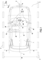
- a road vehicle 1 incorporating a driver assistance system 10 according to a first embodiment is illustrated in Figs. 1 and 2 .
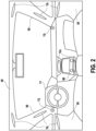
- This road vehicle 1 may comprise a cabin, shown in Fig. 2 , with a driver's seat 20, and doors 30 at either side of the driver's seat 20.
- the system 10 may comprise interior lighting devices 12r,12l,12c, a sound-emitting device 13, a data processing unit 14 connected to the interior lighting devices 12r, 121, 12c and sound-emitting device 13, and one or more imaging sensors 15, connected to the data processing unit 14.
- the lateral interior lighting devices 12r, 121 may be respectively located to the right and left of the driver's seat 20, and may in particular be incorporated in the cabin ceiling 40, in the pillars 50 and/or in the doors 30.
- the central interior lighting device 12c may be located in the centre of the cabin and may in particular be incorporated in a centre console 60.
- These interior lighting devices 12r, 121, 12c may comprise light-emitting diodes, possibly arranged in strips and/or arrays.
- the sound-emitting device 13 may include loudspeakers 13r,131 respectively located to the right and left of the driver's seat 20.
- the imaging sensors 15 may in particular include a camera configured to capture images of the road 2 on which the vehicle 1 drives.
- the data processing unit 14 may be configured to receive data from the imaging sensors 15, output a first visual alert through the interior lighting devices 12r, 121 when the data fulfil a first condition, and output an audible alert through the sound-emitting device 13 when the data fulfil a second condition after fulfilling the first condition.
- the data processing unit 14 may be configured to recognize, from images captured by the imaging sensors 15 lane boundaries 3 on the road 2, and determine lateral distances from those images. These lateral distances may be lateral distances d r , d l with respect to the closest lane boundaries 3, measured for example from the corresponding sides of the vehicle 1, or from a vehicle centreline 5.
- the first condition may include whether any one of the lateral distances d r , d l to the lane boundaries 3 falls below a first distance threshold d min1 .
- This distance threshold could be set in absolute or in relative terms, for instance as a fraction of the lane width W between the lane boundaries 3.
- the second condition may include whether any one of the lateral distances d r , d l to the lane boundaries 3 falls below a second distance threshold d min2 , substantially lower than the first threshold d min1 .
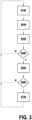
- the driver assistance system 10 may perform an LDA function according to a method which, as illustrated in Fig. 3 , may comprise a step S100 wherein the sensors 15 may capture images of the road 2, a step S200 wherein the data processing unit 14 may recognize the lane boundaries 3 from images captured by the sensors 15 in step S100 and transmitted to the data processing unit 14, a step S300 wherein the data processing unit 14 may determine the lateral distances d r , d l with respect to the closest lane boundaries 3, and a step S400 wherein the data processing unit 14 may determine whether the first condition is fulfilled, namely, in this case, whether any one of the lateral distances d r , d l to the lane boundaries 3 falls below the first distance threshold d min1 .
- step S400 determines, in said step S400, that the first condition is not fulfilled, that is, in this case, that none of the lateral distances d r , d l to the lane boundaries 3 falls below the first threshold d min1 . If the data processing unit 14 determines, however, that one of the lateral distances d r , d l to the lane boundaries 3 falls below the first threshold d min1 , the data processing unit 14 may then, in a subsequent step S500, output the first visual alert through the lateral interior lighting device 12r, 121 on the side closest to a lane boundary 3.
- This first visual alert may take the form of a change of light intensity and/or color from that interior lighting device 12r, 121 on the side closest to a lane boundary 3, eventually together with the central interior lighting device 12c, for instance by flashing once or repeatedly. The driver may thus be gently alerted to the lane departure and advised to focus on the road through the peripheral vision.
- the data processing unit 14 may then determine whether the second condition is fulfilled, namely, in this case, whether any one of the lateral distances d r , d l to the lane boundaries 3 falls below the second distance threshold d min2 . If the data processing unit 14 determines, in said step S600, that the second condition is not fulfilled, that is, in this case, that none of the lateral distances d r , d l to the lane boundaries 3 falls below the second threshold d min2 , the process may be restarted at step S100.
- the data processing unit 14 may then, in a subsequent step S700, output an audible alert through the sound-emitting device 13, alone or together with a second visual alert.
- the sound-emitting device 13 includes loudspeakers 13r,13l respectively located to the right and left of the driver's seat 20, the audible alert may be louder on the side closest to a lane boundary 3. The driver may thus be more insistently alerted to the aggravated risk of a lane departure.
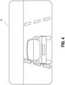
- the driver assistance system 10 may include, alternatively or complementarily to the interior lighting devices 12r, 121, 12c, a display device 11 connected to the data processing unit 14 for outputting the first and/or second visual alerts.
- the display device 11 may for example be a liquid-crystal display, a LED screen, or an OLED screen, and may be located for example directly in front of the driver's seat 20.
- the display device 11 may for instance schematically illustrate the vehicle 1 with respect to the lane boundaries 3, as in Fig. 4 .
- the first and/or second conditions may relate to a lateral distance d c to a lane centreline 4, equidistant from the two closest lane boundaries 3.
- the data processing unit 14 may be configured to determine, in step S300, said lateral distance d c with respect to a lane centreline 4 equidistant from the two closest lane boundaries 3, and the first and second conditions applied in steps S400 and S600 may include whether the lateral distance d c to the lane centreline 4 exceeds respective first and second distance thresholds d max1 , d max2 , wherein the second distance threshold d max2 may be substantially higher than the first distance threshold d max1 .
- the first and/or second conditions may relate to time thresholds.
- the first and second conditions applied in steps S400 and S600 may include whether any one of the lateral distances d r , d l to the lane boundaries 3 has been below a distance threshold d min for periods exceeding, respectively, a first time threshold t max1 , and a significantly longer second time threshold t max2 , as illustrated in Fig. 5 .
- the first and/or second conditions may be related to a lateral speed and/or acceleration of the road vehicle 1 with respect to the lane boundaries 3 and/or the lane centreline 4.
- the first condition may include whether a lateral speed and/or acceleration of the road vehicle 1 towards one of the lane boundaries 3 and/or away from the lane centreline 4 exceeds a speed and/or acceleration threshold
- the first visual alert may take the form of a change of light intensity and/or color from the interior lighting device 12r, 121 on the side towards which the road vehicle 1 is swerving, eventually together with the central interior lighting device 12c
- the second condition may include whether the lateral distance d r , d l to the lane boundary 3 on the same side falls below a distance threshold d min and/or whether the lateral distance d c with respect to the lane centreline 4 has exceeded a distance threshold d max .
- the driver assistance system 10 may comprise additional sensors such as, for example, steering input sensors, eye tracking sensors and/or physiological sensors, the data processing unit 14 may be connected to these additional sensors and configured to determine a driver alertness level based on data transmitted to the data processing unit 14 by those additional sensors, and the second condition may be related to this driver alertness level.
- the second condition may be whether the driver alertness level is still below a threshold, even after the first visual alert, so that the audible alert will be triggered if the driver is insufficiently alert after the first visual alert.
- time thresholds of the third modification may be applied to periods during which the lateral distance d c to a lane centreline 4 exceeds a distance threshold d max , as in the second modification.
- the first embodiment provides a driver assistance system 10 and method with an LDA function.
- LDA function may be combined with other functions, such as, for example, a BSW function.
- a road vehicle 1 incorporating a driver assistance system 10 according to a second embodiment is illustrated in Fig. 6 .
- This road vehicle 1 may comprise a cabin like that shown in Fig. 2 .
- the system 10 may comprise, apart from the features of the first embodiment, one or more proximity sensors 16, connected to the data processing unit 14, and configured to detect obstacles within a distance threshold d bsw in blind spots 6 around the road vehicle 1.
- the remaining elements of the road vehicle 1 and driver assistance system according to this second embodiment are analogous to those of the first embodiment.
- the data processing unit 14 may be configured to receive data from the proximity sensors 16, as well as from the imaging sensors 15, output a first visual alert through the interior lighting devices 12r, 121 when the data fulfil a first condition, and output an audible alert through the sound-emitting device 13 when the data fulfil a second condition after fulfilling the first condition.
- the data processing unit 14 may be configured to not only recognize, from images captured by the imaging sensors 15 lane boundaries 3 on the road 2, and determine lateral distances from those images, but also to determine, from data captured by the proximity sensors 16, the presence or absence of a potential obstacle 5, within the distance threshold d bsw , in a blind spot 6.
- the first condition may include whether there is a potential obstacle 5 within the distance threshold d bsw , in a blind spot 6.
- the second condition may include whether any one of the lateral distances d r , d l to the lane boundary 3 closest to the potential obstacle 5 falls below another distance threshold d min .
- the driver assistance system 10 may perform combined BSW and LDA functions according to a method as illustrated in Fig. 7 , wherein the data processing unit 14 in step S400 may determine whether the first condition is fulfilled, namely, in this case, from data captured and transmitted by the proximity sensors 16, whether a potential obstacle 5 is present within the distance threshold d bsw , in a blind spot 6. If the data processing unit 14 determines, in said step S400, that the first condition is not fulfilled, that is, in this case, that there is not any potential obstacle 5 within the distance threshold d bsw in a blind spot 6, the process may be restarted at step S400.
- the data processing unit 14 may then, in step S500, output the first visual alert through the lateral interior lighting device 12r, 121 on the side closest to the potential obstacle 5, eventually together with the central interior lighting device 12c.
- This first visual alert may take the form of a change of light intensity and/or color from that lateral interior lighting device 12r, 121 on the side closest to the potential obstacle 5, eventually together with the central interior lighting device 12c, for instance by flashing once or repeatedly. The driver may thus be gently alerted to the obstacle through the peripheral vision.
- the sensors 15 may capture images of the road 2, the data processing unit 14 may recognize the lane boundaries 3 from images captured by the sensors 15 and transmitted to the data processing unit 14, and the data processing unit 14 may determine the lateral distances d r , d l with respect to the closest lane boundaries 3, as in the first embodiment.
- the data processing unit 14 may then determine whether the second condition is fulfilled, namely, in this case, whether the lateral distance d r , d l to the lane boundary 3 closest to the potential obstacle 5 falls below a distance threshold d min .
- step S600 If the data processing unit 14 determines, in said step S600, that the second condition is not fulfilled, that is, in this case, that the lateral distance d r , d l to the lane boundary 3 closest to the potential obstacle 5 does not fall below the distance threshold d min2 , the process may be restarted at step S400. If the data processing unit 14 determines, however, that the lateral distance d r , d l to the lane boundary 3 closest to the potential obstacle 5 falls below the distance threshold d min , the data processing unit 14 may then, in step S700, output an audible alert through the sound-emitting device 13, alone or together with a second visual alert.
- the sound-emitting device 13 includes loudspeakers 13r,13l respectively located to the right and left of the driver's seat 20, the audible alert may be louder on the side closest to the potential obstacle.
- the driver may thus be more insistently alerted to the aggravated risk, because of a lane departure, of a collision against an obstacle within a blind spot.
- the driver assistance system 10 may include, alternatively or complementarily to the interior lighting devices 12r, 121, 12c, a display device 11 connected to the data processing unit 14 for outputting the first and/or second visual alerts.
- the display device 11 may for example be a liquid-crystal display, a LED screen, or an OLED screen, and may be located for example directly in front of the driver's seat 20.
- the display device 11 may for instance schematically illustrate the vehicle 1 with respect to the lane boundaries 3 and obstacle 5, as in Fig. 8 .
- the second condition may relate to a lateral distance d c to a lane centreline 4, equidistant from the two closest lane boundaries 3.
- the data processing unit 14 may be configured to determine, in step S300, said lateral distance d c with respect to a lane centreline 4 equidistant from the two closest lane boundaries 3, and the second condition applied in steps S600 may include whether the lateral distance d c with respect to the lane centreline 4, in the direction of the obstacle 5, exceeds a distance threshold d max .
- the first and/or second conditions may relate to time thresholds.
- the first and second conditions applied in steps S400 and S600 may include whether the potential obstacle 5 in blind spot 6 has been within the distance threshold d bsw for periods exceeding, respectively, a first time threshold t max1 , and a significantly longer second time threshold t max2 , as illustrated in Fig. 5 .
- the second condition may be related to a lateral speed and/or acceleration of the road vehicle 1 with respect to the lane boundaries 3 and/or the lane centreline 4.
- the second condition may include whether a lateral speed and/or acceleration of the road vehicle 1 towards the lane boundary 3 closest to obstacle 5 and/or away from the lane centreline 4 in the direction of obstacle 5 exceeds a speed and/or acceleration threshold.
- the driver assistance system 10 may comprise additional sensors such as, for example, steering input sensors, eye tracking sensors and/or physiological sensors, the data processing unit 14 may be connected to these additional sensors and configured to determine a driver alertness level based on data transmitted to the data processing unit 14 by those additional sensors, and the second condition may be related to this driver alertness level.
- the second condition may be whether the driver alertness level is still below a threshold, even after the first visual alert, so that the audible alert will be triggered if the driver is insufficiently alert after the first visual alert.
- a time threshold as in the third modification may be applied to a period during which the lateral distance d c to a lane centreline 4 exceeds a distance threshold d max , as in the second modification.
Priority Applications (4)
| Application Number | Priority Date | Filing Date | Title |
|---|---|---|---|
| EP21306848.9A EP4197838A1 (fr) | 2021-12-20 | 2021-12-20 | Procédé et système d'assistance à un conducteur d'un véhicule routier |
| CN202211279082.9A CN116279553A (zh) | 2021-12-20 | 2022-10-19 | 用于辅助道路车辆的驾驶员的方法和系统 |
| JP2022170220A JP2023091737A (ja) | 2021-12-20 | 2022-10-24 | 道路車両の運転者を支援する方法とシステム |
| US17/974,654 US20230192115A1 (en) | 2021-12-20 | 2022-10-27 | Method and system for assisting a driver of a road vehicle |
Applications Claiming Priority (1)
| Application Number | Priority Date | Filing Date | Title |
|---|---|---|---|
| EP21306848.9A EP4197838A1 (fr) | 2021-12-20 | 2021-12-20 | Procédé et système d'assistance à un conducteur d'un véhicule routier |
Publications (1)
| Publication Number | Publication Date |
|---|---|
| EP4197838A1 true EP4197838A1 (fr) | 2023-06-21 |
Family
ID=79316865
Family Applications (1)
| Application Number | Title | Priority Date | Filing Date |
|---|---|---|---|
| EP21306848.9A Pending EP4197838A1 (fr) | 2021-12-20 | 2021-12-20 | Procédé et système d'assistance à un conducteur d'un véhicule routier |
Country Status (4)
| Country | Link |
|---|---|
| US (1) | US20230192115A1 (fr) |
| EP (1) | EP4197838A1 (fr) |
| JP (1) | JP2023091737A (fr) |
| CN (1) | CN116279553A (fr) |
Families Citing this family (1)
| Publication number | Priority date | Publication date | Assignee | Title |
|---|---|---|---|---|
| CA3141463A1 (fr) * | 2019-06-05 | 2020-12-10 | Tesman Rd S.R.L.S | Systeme d'aide a l'orientation pour aveugles |
Citations (6)
| Publication number | Priority date | Publication date | Assignee | Title |
|---|---|---|---|---|
| EP1918896A1 (fr) | 2006-10-30 | 2008-05-07 | MAGNETI MARELLI SISTEMI ELETTRONICI S.p.A. | Système de suivi/changement de voie amélioré et mode de fonctionnement correspondant |
| US20140240114A1 (en) * | 2011-11-01 | 2014-08-28 | Volkswagen Aktiengesellschaft | Method for outputting alert messages of a driver assistance system and associated driver assistance system |
| US20160288709A1 (en) * | 2015-04-02 | 2016-10-06 | Denso International America, Inc. | Visual Alert System |
| US20160342850A1 (en) * | 2015-05-18 | 2016-11-24 | Mobileye Vision Technologies Ltd. | Safety system for a vehicle to detect and warn of a potential collision |
| EP3269607A1 (fr) * | 2016-07-14 | 2018-01-17 | LG Electronics Inc. | Appareil d'assistance à la conduite pour véhicule |
| KR20210111558A (ko) * | 2020-03-03 | 2021-09-13 | 현대자동차주식회사 | 운전자 보조 장치 및 그의 경고 방법 |
-
2021
- 2021-12-20 EP EP21306848.9A patent/EP4197838A1/fr active Pending
-
2022
- 2022-10-19 CN CN202211279082.9A patent/CN116279553A/zh active Pending
- 2022-10-24 JP JP2022170220A patent/JP2023091737A/ja active Pending
- 2022-10-27 US US17/974,654 patent/US20230192115A1/en not_active Abandoned
Patent Citations (6)
| Publication number | Priority date | Publication date | Assignee | Title |
|---|---|---|---|---|
| EP1918896A1 (fr) | 2006-10-30 | 2008-05-07 | MAGNETI MARELLI SISTEMI ELETTRONICI S.p.A. | Système de suivi/changement de voie amélioré et mode de fonctionnement correspondant |
| US20140240114A1 (en) * | 2011-11-01 | 2014-08-28 | Volkswagen Aktiengesellschaft | Method for outputting alert messages of a driver assistance system and associated driver assistance system |
| US20160288709A1 (en) * | 2015-04-02 | 2016-10-06 | Denso International America, Inc. | Visual Alert System |
| US20160342850A1 (en) * | 2015-05-18 | 2016-11-24 | Mobileye Vision Technologies Ltd. | Safety system for a vehicle to detect and warn of a potential collision |
| EP3269607A1 (fr) * | 2016-07-14 | 2018-01-17 | LG Electronics Inc. | Appareil d'assistance à la conduite pour véhicule |
| KR20210111558A (ko) * | 2020-03-03 | 2021-09-13 | 현대자동차주식회사 | 운전자 보조 장치 및 그의 경고 방법 |
Also Published As
| Publication number | Publication date |
|---|---|
| JP2023091737A (ja) | 2023-06-30 |
| CN116279553A (zh) | 2023-06-23 |
| US20230192115A1 (en) | 2023-06-22 |
Similar Documents
| Publication | Publication Date | Title |
|---|---|---|
| US7777619B2 (en) | System and method for implementing active safety counter measures for an impaired driver | |
| EP2523839B1 (fr) | Détections conducteur et environnement combinées pour systèmes de sécurité de véhicule | |
| US20160009295A1 (en) | On-vehicle situation detection apparatus and method | |
| JPH097099A (ja) | 警報装置 | |
| KR101938314B1 (ko) | 운전 습관에 따른 후측방 경보 장치 및 방법 | |
| JP2009018625A (ja) | 走行制御装置 | |
| US11279371B2 (en) | Method, system and vehicle for use of an object displaying device in a vehicle | |
| KR20180065527A (ko) | 차량 후측방 경고 장치 및 이를 이용한 경고 방법 | |
| US20230192115A1 (en) | Method and system for assisting a driver of a road vehicle | |
| JP6223143B2 (ja) | 運転支援装置および運転支援方法 | |
| JP4337130B2 (ja) | 運転装置の制御装置 | |
| JP4337131B2 (ja) | 移動体制御装置 | |
| JP6811743B2 (ja) | 安全運転支援装置 | |
| EP3582493B1 (fr) | Système d'affichage d'images dans un véhicule et procédé de traitement d'images | |
| JP6579496B2 (ja) | 運転者状態推定装置 | |
| JP4900146B2 (ja) | 障害物検知装置 | |
| JP7441417B2 (ja) | ドライバ状態推定装置 | |
| WO2022258150A1 (fr) | Procédé mis en œuvre par ordinateur d'aide à un conducteur, produit-programme informatique, système d'aide à la conduite et véhicule | |
| JP7043795B2 (ja) | 運転支援装置、運転状況情報取得システム、運転支援方法及びプログラム | |
| JP2021077137A (ja) | 運転者状態推定装置 | |
| WO2018168050A1 (fr) | Dispositif de détermination de niveau de concentration, procédé de détermination de niveau de concentration, et programme permettant de déterminer le niveau de concentration | |
| JP7393738B2 (ja) | ドライバ状態推定装置 | |
| WO2018168048A1 (fr) | Dispositif de détermination de degré de concentration, procédé de détermination de degré de concentration, et programme permettant de déterminer un degré de concentration | |
| EP4105083A1 (fr) | Système de surveillance pour véhicule | |
| WO2022210038A1 (fr) | Dispositif d'aide à la conduite, procédé d'aide à la conduite, et programme d'aide à la conduite |
Legal Events
| Date | Code | Title | Description |
|---|---|---|---|
| PUAI | Public reference made under article 153(3) epc to a published international application that has entered the european phase |
Free format text: ORIGINAL CODE: 0009012 |
|
| STAA | Information on the status of an ep patent application or granted ep patent |
Free format text: STATUS: REQUEST FOR EXAMINATION WAS MADE |
|
| 17P | Request for examination filed |
Effective date: 20211220 |
|
| AK | Designated contracting states |
Kind code of ref document: A1 Designated state(s): AL AT BE BG CH CY CZ DE DK EE ES FI FR GB GR HR HU IE IS IT LI LT LU LV MC MK MT NL NO PL PT RO RS SE SI SK SM TR |
|
| STAA | Information on the status of an ep patent application or granted ep patent |
Free format text: STATUS: THE APPLICATION IS DEEMED TO BE WITHDRAWN |