EP4197801B1 - Drucker und führungsschiene für einen druckkopfwagen - Google Patents
Drucker und führungsschiene für einen druckkopfwagen Download PDFInfo
- Publication number
- EP4197801B1 EP4197801B1 EP21216158.2A EP21216158A EP4197801B1 EP 4197801 B1 EP4197801 B1 EP 4197801B1 EP 21216158 A EP21216158 A EP 21216158A EP 4197801 B1 EP4197801 B1 EP 4197801B1
- Authority
- EP
- European Patent Office
- Prior art keywords
- mounting
- printer
- guidance rail
- sites
- guidance
- Prior art date
- Legal status (The legal status is an assumption and is not a legal conclusion. Google has not performed a legal analysis and makes no representation as to the accuracy of the status listed.)
- Active
Links
Images


Classifications
-
- B—PERFORMING OPERATIONS; TRANSPORTING
- B41—PRINTING; LINING MACHINES; TYPEWRITERS; STAMPS
- B41J—TYPEWRITERS; SELECTIVE PRINTING MECHANISMS, i.e. MECHANISMS PRINTING OTHERWISE THAN FROM A FORME; CORRECTION OF TYPOGRAPHICAL ERRORS
- B41J19/00—Character- or line-spacing mechanisms
-
- B—PERFORMING OPERATIONS; TRANSPORTING
- B41—PRINTING; LINING MACHINES; TYPEWRITERS; STAMPS
- B41J—TYPEWRITERS; SELECTIVE PRINTING MECHANISMS, i.e. MECHANISMS PRINTING OTHERWISE THAN FROM A FORME; CORRECTION OF TYPOGRAPHICAL ERRORS
- B41J29/00—Details of, or accessories for, typewriters or selective printing mechanisms not otherwise provided for
- B41J29/02—Framework
Definitions
- the present invention generally pertains to a printer with a print head carriage movably mounted on two guidance rails with reduced susceptibility to vibrations.
- a print head carriage In many types of printers, a print head carriage is moved relative to a medium such as a sheet or a roll of paper or foil of plastic or the like. Such printers are also sometimes designated as “scanning printing systems".
- the “scanning printing systems” comprise a carriage configured to, in printing operation, move in reciprocation in a main scanning direction over the medium.
- the print head carriage carries a print head, which marks the medium with a marking agent such as ink or a conductive paste in order to create text, patterns, colors, images, electrical circuits and/or the like on the medium.
- the print head carriage typically moves bidirectionally along a linear path and is typically mounted between two so-called runner blocks, which in turn are moveably arranged on a respective one of two guidance rails installed in parallel in the printer.
- the mounting of such a guidance rail in a carriage printing system is usually designed to be equidistant, for example with a mounting pitch of 60 millimeters.
- EP 3 564 038 A1 discloses a guiding structure for a print head carriage in which equidistant mounting sites are provided for an array of mounting bodies for mounting the guiding structure to the rest of the printer.
- US 2018/079 240 A1 describes an assembly for moving a carriage of a printer. Regarding a vibration problem that may arise when the carriage moves, it is suggested to include a flexible support element and a tensioner assembly for tensioning the flexible support element. By controlling the tension of the flexible support element, it is endeavored to dampen vibrations of the assembly caused by the movement of the carriage.
- US 2020/047527 A1 discloses a printer with a guiding structure according to the preamble of claim 1.
- the typical equidistant arrangement of the mounting sites of the guidance rail may lead to an undesired increase in vibration in and of the guidance rail due to the movement of the print head carriage.
- this induces vibrations in the guidance rail.
- the guidance rail is fixated at each of the mounting sites which are equidistant in the prior art, this creates a regular pattern of fixed points. Between these fixed points at the mounting sites, the guidance rail is comparatively freer to shift. Consequently, such a guidance rail installed in a printer is susceptible to particular vibration frequencies induced by the print head carriage, in particular to frequencies that are integer multiplies of the base distance between the mounting sites. Vibrations in the guidance rail, in turn, negatively affect the longevity and the precision of the print head carriage.
- the invention provides a printer according to claim 1.
- the mounting sites of the guidance rail are non-equidistant overall as there is at least one distance between one pair of adjacent mounting sites which is different from at least one other distance between one other pair of adjacent mounting sites (wherein the one pair and the other pair may have at most one mounting site in common).
- the strict regularity of the arrangement of mounting sites is removed and the susceptibility of the guidance rail to vibrations is reduced. It is preferred that there is a plurality of first distances between adjacent mounting sites which are different from a plurality of second distances between adjacent mounting sites. In general, the less regular the arrangement of mounting sites on the guidance rail is, the less susceptible the guidance rail is to vibrations.
- the mounting site being arranged essentially in a row may be understood to mean that they are arranged in a strict row as much as usual tolerances allow or that they are arranged in a row with perpendicular deviations of each mounting site from an ideal, strict row between (including) zero and a maximum deviation value, MDV.
- the MDV may as low as zero and as large as, for example, the size of the mounting site in the direction perpendicular to the ideal, strict row. This direction may also be simply designated as the "perpendicular direction", i.e., perpendicular to the longitudinal direction along which the guidance rail itself extends.
- the maximum distance between any two mounting sites in the perpendicular direction may be two times MDV, in case that one of the mounting site is maximally deviated in the positive perpendicular direction and another one of the mounting sites is maximally deviated in the negative perpendicular direction.
- equidistant center positions for the mounting sites are defined, each mounting site is arranged within a predefined tolerance interval around a respective one of the center positions, and the relative position of each mounting site to the respective center position is different for at least two of the mounting sites. In each tolerance interval, there is only a single center position and only a single mounting site.
- the equidistant center positions have the effect that the guidance rail is, on average, fastened to the printer at regular (equidistant) intervals such that at no point of the guidance rail there is an excess of play.
- the mounting sites are not arranged exactly at the center positions but at (at least partially, i.e., at least for some mounting sites) different relative positions thereto, the strict regularity of the mounting sites is advantageously broken, and the guidance rail is less susceptible to vibrations.
- each mounting site is randomly arranged within the predefined tolerance interval around its respective center position. This strongly reduces the chances that the guidance rail has any resonance frequency that can be excited by the movement of the carriage.
- the term "randomly” shall here be understood to include both true randomness as well as pseudo-randomness in the mathematical sense.
- each distance between any two adjacent mounting sites is different. This is another way to strongly reduce the chances that the guidance rail has any resonance frequency that can be excited by the movement of the print head carriage.
- At least two different distance values are defined for adjacent mounting sites, and wherein the at least two different distance values alternate regularly along the row of mounting sites. It should be noted that whenever herein distances between mounting sites are discussed, this pertains to distances between adjacent mounting sites unless explicitly specified otherwise.
- Two different distances values A, B mean that the distances between pairs of adjacent mounting sites along the longitudinal direction vary as A-B-A-B-A... and so on.
- the order may be A-B-C-A-B-C-A ... and so on.
- the largest resonance frequency would be the largest common divisor of A, B, C, ... and so on which will in general be the smaller, the more different distance values, A, B, C, D, ... and so on are present.
- the ratio of adjacently applied distance values is between 1:1 and 1:5, preferably between 1:2 and 1:4, more preferably between 1:3 and 1:4.
- the mounting sites are configured as holes or bores through which mounting elements for mounting the guidance rail to the printer can be inserted.
- the mounting elements may in particular be mounting means such as screws, bolts, and/or the like.
- the extent of the hole or bore in the perpendicular direction, as a percentage of the extent of the guidance rail itself along the perpendicular direction, is preferably larger than 50%, more preferably larger than 70%.
- the invention further provides a printer comprising at least one guidance rail according to an embodiment of the present invention, the at least one guidance rail being mounted to the printer by mounting elements attached at the mounting sites of the guidance rail.
- the at least one guidance rail being mounted to the printer by mounting elements attached at the mounting sites of the guidance rail.
- at least (or exactly) two guidance rails are provided and mounted to the printer, more preferably in parallel for providing additional stability to the moving print head carriage.
- first, second, third, ... and so on mounting sites of the first guidance rail are positioned at different positions along the longitudinal direction than the respective first, second, third, ... and so on mounting sites of the second guidance rail. This will further reduce the susceptibility of the assembly of the guidance rails and the print head carriage to vibrations. In other words, starting from a mounting site of a first guidance rail and moving towards another guidance rail along the perpendicular direction, it is preferred if no other mounting site is encountered at the same position with respect to the longitudinal direction.
- Fig. 1 schematically illustrates a part of a printer 100 according to an embodiment of the present invention.
- Parts of the printer 100 which are well known but not essential for the description of the present invention are omitted for the sake of clarity.
- no housing, medium transport system, print head and so on are shown although they will typically be present in the printer 100.
- the printer comprises, among other parts, two guidance rails 10 arranged in parallel to one another, each extending along a (the same) longitudinal direction L but at a perpendicular distance from one another.
- mounting sites 12 are provided which will be described in more detail in the following.
- a print head carriage 150 is moveably mounted between the guidance rails 10 such as to be moveable by an actuator (not shown) bidirectionally in the longitudinal direction L.
- the print head carriage 150 would carry a print head configured to eject the marking agent (e.g. ink) in the downward direction.
- the distances between the mounting sites 12 are not shown to scale in Fig. 1 .
- Fig. 2 shows further details of the assembly shown in Fig. 1 , with the print head carriage 150 now left out.
- the mounting sites 12 are provided as holes or bores in the guidance rail 10.
- the holes or bores may be punched out of a blank metal strip to produce a metal guidance rail 10, or they may be bored out of a blank metal strip.
- the guidance rail 10 could also be made from plastic in which case the mounting sites 12 may be cut into a blank plastic strip to produce a plastic guidance rail 10, or the guidance rail 10 may be produced by injections molding as already comprising the holes, or the guidance rail 10 may be produced by additive manufacturing (e.g. "3D printing") from a material comprising (or consisting of) metal, plastic and/or ceramics as already comprising the holes.
- Fig. 2 also shows that the guidance rail 10 may be mounted to a framework 110 of the printer 100 (or any other part of the printer 100) using mounting elements 13. These mounting elements 13 may be any type of mounting means, for example, screws or bolts.
- a runner block 14 is moveably mounted to the guidance rail 10 such as to be able to move along the longitudinal direction L.
- the print head carriage 150 may be mounted on at least one runner block 14 on each guidance rail 10.
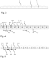
- FIG. 3 schematically illustrates a guidance rail 1 according to the prior art (e.g. according to EP 3 564 038 A1 ), wherein mounting sites 4 are arranged at equidistant intervals.
- a schematic graph 5 indicates in an exaggerated manner how much play the different portions of the guidance rail 1 have due to the positioning of the mounting sites 4: the play is minimal at each mounting site 4, increases up towards a maximum precisely halfway between that mounting site 4 and the next, and then decreases again to the minimum.
- the regularity of this graph 5 indicates the susceptibility of the guidance rail 1 of the prior art to vibrations, as the graph 5 can also be interpreted to show the fundamental vibration mode between adjacent mounting sites 4.
- Fig. 4 schematically illustrates a guidance rail 10 according to an embodiment of the present invention.
- equidistant center positions 16-1, 16-2, 16-3, ... (in short: 16-i) are defined for the mounting sites 12-1, 12-2, ... (in short: 12-i).
- the center positions 16-i are marked by diamond symbols and the mounting sites 12-I by circles.
- Each center position 16-i is at the center of a periodically repeating cell 15. Both the center positions 16-i and the cell 15 are not necessarily marked on the guidance rail in any way but are defined and described in order to understand the embodiment better.
- Each mounting site 12-i is arranged within a predefined tolerance interval around a (or: its) respective one of the center positions 16-i.
- the tolerance interval in this respect is preferably only considered along the longitudinal direction L.
- the tolerance interval is preferably arranged symmetrically around its respective center position 16-i, or, in other words, each center position 16-i is arranged at the center (in the longitudinal direction L) of its respective tolerance interval.
- each mounting site 12-i to the (or: its) respective center position 16-i is different for at least two of the mounting sites 12-i.
- Fig. 4 shows a distance d12 between a first mounting site 12-1 and a second mounting site 12-2 being smaller than a distance d23 between the second mounting site 12-2 and a third mounting site 12-3.
- the total width of the tolerance interval is smaller than the (constant and equal throughout the guidance rail 10) distance between two adjacent center positions 16-i, 16-(i+1), more preferably smaller than 75% of that distance, most preferably smaller than 50% of that distance.
- this provides a suitable balance between the advantages of different distances d12, d23, ... between the mounting sites 12-1, 12-2, ...(in order to reduce vibration) and the advantages of equidistant distances (in order to provide stability of the mounting of the guidance rail 10 to the printer 100).
- each mounting site 12-i (and only one) is randomly arranged within the predefined tolerance interval around its respective center position 16-i.
- a graph 5 has been included as well which, as in Fig. 3 , indicates (in an exaggerated manner) the play that the guidance rail 10 has in the perpendicular direction P and, consequently, also the fundamental mode of vibration. Because of the different distances d12, d23, ... it is evident that also these fundamental modes of graph 5 in Fig. 4 are (preferably) all different and that therefore no vibrational mode of the guidance rail 10 as a whole can be induced.
- Fig. 5 schematically illustrates a guidance rail 20 according to another embodiment of the present invention.
- two different distance values are defined for adjacent mounting sites 12-i, and the two different distance values A and B alternate regularly along the row of mounting sites 12-i.
- the ratio of adjacently applied distance values is between 1:1 and 1:5, preferably between 1:2 and 1:4, more preferably between 1:3 and 1:4.
- One basic idea of the invention may be summarized as follows: distances between mounting sites of a guidance rail for a print head carriage are provided non-equidistantly in order to reduce vibration modes and therefore reduce the chances and intensity of vibrations induced the in the guidance rail by the dynamic movement of the print head carriage.
Landscapes
- Character Spaces And Line Spaces In Printers (AREA)
Claims (7)
- Drucker (100) mit einem Druckkopfwagen (150) und mit zwei parallel angeordneten Führungsschienen (10; 20), wobei auf jeder Führungsschiene (10; 20) mindestens ein Führungswagen (14) beweglich gelagert ist und der Druckkopfwagen (150) auf den mindestens zwei Führungswagen (16) gelagert ist, wobei die beiden Führungsschienen (10; 20) durch an Montagestellen (12-i) der Führungsschiene (10; 20) angebrachte Montageelemente (13) an dem Drucker (100) montiert sind,wobei die Befestigungsstellen (12-i) im Wesentlichen in einer Reihe angeordnet und zum Anbringen von Befestigungselementen (13) für die Befestigung der Führungsschiene (10; 20) am Drucker (100) ausgebildet sind,dadurch gekennzeichnet, dassmindestens zwei Abstände (d12, d23, d34) zwischen beliebigen benachbarten Einbaustellen (12-i, 12-(i+1)) ungleich sind.
- Der Drucker (10; 20) nach Anspruch 1,
wobei äquidistante Mittelpositionen (16-i) für die Montagestellen (12-i) definiert sind, jede Montagestelle (12-i) innerhalb eines vordefinierten Toleranzintervalls um eine jeweilige der Mittelpositionen (16-i) angeordnet ist und die relative Position jeder Montagestelle (12-i) zu der jeweiligen Mittelposition (16-i) für mindestens zwei der Montagestellen (12-i) unterschiedlich ist. - Der Drucker (10; 20) nach Anspruch 2,
wobei jede Montagestelle (12-i) zufällig innerhalb des vordefinierten Toleranzintervalls um ihre jeweilige Mittelposition (16-i) angeordnet ist. - Der Drucker (10; 20) nach einem der Patentansprüche 1 bis 3,
wobei jeder Abstand (d12, d23) zwischen zwei benachbarten Montageplätzen (12-1, 12-2) unterschiedlich ist. - Der Drucker (10; 20) nach Anspruch 1,
wobei mindestens zwei unterschiedliche Abstandswerte (A, B) für benachbarte Montagestellen (12-i) definiert sind, und wobei die mindestens zwei unterschiedlichen Abstandswerte (A, B) regelmäßig entlang der Reihe von Montagestellen (12-i) abwechseln. - Der Drucker (10; 20) nach Anspruch 5,
wobei das Verhältnis der nebeneinander liegenden Abstandswerte (A, B) zwischen 1:1 und 1:5, vorzugsweise zwischen 1:2 und 1:4, besonders bevorzugt zwischen 1:3 und 1:4 liegt. - Der Drucker (10; 20) nach einem der Patentansprüche 1 bis 5,
wobei die Befestigungsstellen (12-i) als Löcher oder Bohrungen ausgebildet sind, durch die Befestigungselemente (13) zur Befestigung der Führungsschiene (10; 20) an dem Drucker (100) eingesetzt werden können.
Priority Applications (1)
| Application Number | Priority Date | Filing Date | Title |
|---|---|---|---|
| EP21216158.2A EP4197801B1 (de) | 2021-12-20 | 2021-12-20 | Drucker und führungsschiene für einen druckkopfwagen |
Applications Claiming Priority (1)
| Application Number | Priority Date | Filing Date | Title |
|---|---|---|---|
| EP21216158.2A EP4197801B1 (de) | 2021-12-20 | 2021-12-20 | Drucker und führungsschiene für einen druckkopfwagen |
Publications (2)
| Publication Number | Publication Date |
|---|---|
| EP4197801A1 EP4197801A1 (de) | 2023-06-21 |
| EP4197801B1 true EP4197801B1 (de) | 2024-12-04 |
Family
ID=78957819
Family Applications (1)
| Application Number | Title | Priority Date | Filing Date |
|---|---|---|---|
| EP21216158.2A Active EP4197801B1 (de) | 2021-12-20 | 2021-12-20 | Drucker und führungsschiene für einen druckkopfwagen |
Country Status (1)
| Country | Link |
|---|---|
| EP (1) | EP4197801B1 (de) |
Family Cites Families (6)
| Publication number | Priority date | Publication date | Assignee | Title |
|---|---|---|---|---|
| US8944547B2 (en) * | 2010-01-26 | 2015-02-03 | Canon Kabushiki Kaisha | Recording apparatus |
| TWI441742B (zh) * | 2010-04-12 | 2014-06-21 | Cal Comp Electronics & Comm Co | 用於承載列印頭之軸軌固定結構及其固定方法及列印機器 |
| JP6748371B2 (ja) * | 2015-10-20 | 2020-09-02 | セイコーエプソン株式会社 | 液体吐出装置及び液体吐出装置におけるレール部の調整方法 |
| US10343430B2 (en) | 2016-09-22 | 2019-07-09 | Océ Holding B.V. | Assembly for moving a carriage |
| EP3564038A1 (de) | 2018-05-04 | 2019-11-06 | OCE Holding B.V. | Führungsstruktur für einen druckkopfschlitten |
| EP3608114B1 (de) * | 2018-08-10 | 2023-06-07 | Canon Production Printing Holding B.V. | Anordnung einer führungsstruktur und eines druckkopfwagens |
-
2021
- 2021-12-20 EP EP21216158.2A patent/EP4197801B1/de active Active
Also Published As
| Publication number | Publication date |
|---|---|
| EP4197801A1 (de) | 2023-06-21 |
Similar Documents
| Publication | Publication Date | Title |
|---|---|---|
| CN102152634A (zh) | 喷墨打印装置 | |
| US20100053252A1 (en) | Liquid discharging apparatus and method of controlling liquid discharging apparatus | |
| EP1364790B1 (de) | Farbstrahlschreibkopf mit mehreren Aktoreinheiten und mit einer vielzahl von Verteilungskammern | |
| EP4197801B1 (de) | Drucker und führungsschiene für einen druckkopfwagen | |
| US7192118B2 (en) | Droplet ejecting head and droplet ejecting apparatus | |
| EP3069878A1 (de) | Druckvorrichtung und druckverfahren | |
| ATE322987T1 (de) | Führungsanordnung für tintenstrahldrucker | |
| EP3293003A1 (de) | Tintenstrahlkopfantriebsvorrichtung und tintenstrahlkopf | |
| US5924804A (en) | Information recording head | |
| US6350011B1 (en) | Print head arrangement | |
| HK2097A (en) | Dot type printing head for use in a serial printer | |
| KR102084934B1 (ko) | 라인 헤드 및 잉크젯 장치 | |
| JP2881616B2 (ja) | インクジェット式ヘッド装置 | |
| US20030227511A1 (en) | Scan axis assembly for a printer | |
| US4365902A (en) | Wire matrix print head | |
| US8562105B2 (en) | Fixing structure for print head carriage rod and fixing method thereof | |
| JP2010094841A (ja) | 液体吐出装置 | |
| JP5074842B2 (ja) | ワイヤドット印字ヘッド及びプリンタ | |
| JP4402658B2 (ja) | インクジェット記録装置 | |
| CN222645655U (zh) | 一种拼接打印头和喷墨打印机 | |
| CN110154544B (zh) | 用于喷墨的印刷杆 | |
| KR20160026708A (ko) | 액체 토출 장치 및 액체 토출 헤드 | |
| JP2005186598A (ja) | 画像記録装置 | |
| JP2024020066A (ja) | インクジェット装置 | |
| JP2005186599A (ja) | 画像記録装置 |
Legal Events
| Date | Code | Title | Description |
|---|---|---|---|
| PUAI | Public reference made under article 153(3) epc to a published international application that has entered the european phase |
Free format text: ORIGINAL CODE: 0009012 |
|
| STAA | Information on the status of an ep patent application or granted ep patent |
Free format text: STATUS: THE APPLICATION HAS BEEN PUBLISHED |
|
| AK | Designated contracting states |
Kind code of ref document: A1 Designated state(s): AL AT BE BG CH CY CZ DE DK EE ES FI FR GB GR HR HU IE IS IT LI LT LU LV MC MK MT NL NO PL PT RO RS SE SI SK SM TR |
|
| STAA | Information on the status of an ep patent application or granted ep patent |
Free format text: STATUS: REQUEST FOR EXAMINATION WAS MADE |
|
| 17P | Request for examination filed |
Effective date: 20231221 |
|
| RBV | Designated contracting states (corrected) |
Designated state(s): AL AT BE BG CH CY CZ DE DK EE ES FI FR GB GR HR HU IE IS IT LI LT LU LV MC MK MT NL NO PL PT RO RS SE SI SK SM TR |
|
| GRAP | Despatch of communication of intention to grant a patent |
Free format text: ORIGINAL CODE: EPIDOSNIGR1 |
|
| STAA | Information on the status of an ep patent application or granted ep patent |
Free format text: STATUS: GRANT OF PATENT IS INTENDED |
|
| INTG | Intention to grant announced |
Effective date: 20240710 |
|
| GRAS | Grant fee paid |
Free format text: ORIGINAL CODE: EPIDOSNIGR3 |
|
| GRAA | (expected) grant |
Free format text: ORIGINAL CODE: 0009210 |
|
| STAA | Information on the status of an ep patent application or granted ep patent |
Free format text: STATUS: THE PATENT HAS BEEN GRANTED |
|
| AK | Designated contracting states |
Kind code of ref document: B1 Designated state(s): AL AT BE BG CH CY CZ DE DK EE ES FI FR GB GR HR HU IE IS IT LI LT LU LV MC MK MT NL NO PL PT RO RS SE SI SK SM TR |
|
| REG | Reference to a national code |
Ref country code: CH Ref legal event code: EP |
|
| REG | Reference to a national code |
Ref country code: DE Ref legal event code: R096 Ref document number: 602021022796 Country of ref document: DE |
|
| REG | Reference to a national code |
Ref country code: IE Ref legal event code: FG4D |
|
| REG | Reference to a national code |
Ref country code: NL Ref legal event code: FP |
|
| REG | Reference to a national code |
Ref country code: LT Ref legal event code: MG9D |
|
| PG25 | Lapsed in a contracting state [announced via postgrant information from national office to epo] |
Ref country code: HR Free format text: LAPSE BECAUSE OF FAILURE TO SUBMIT A TRANSLATION OF THE DESCRIPTION OR TO PAY THE FEE WITHIN THE PRESCRIBED TIME-LIMIT Effective date: 20241204 |
|
| PG25 | Lapsed in a contracting state [announced via postgrant information from national office to epo] |
Ref country code: FI Free format text: LAPSE BECAUSE OF FAILURE TO SUBMIT A TRANSLATION OF THE DESCRIPTION OR TO PAY THE FEE WITHIN THE PRESCRIBED TIME-LIMIT Effective date: 20241204 |
|
| PG25 | Lapsed in a contracting state [announced via postgrant information from national office to epo] |
Ref country code: BG Free format text: LAPSE BECAUSE OF FAILURE TO SUBMIT A TRANSLATION OF THE DESCRIPTION OR TO PAY THE FEE WITHIN THE PRESCRIBED TIME-LIMIT Effective date: 20241204 |
|
| PG25 | Lapsed in a contracting state [announced via postgrant information from national office to epo] |
Ref country code: ES Free format text: LAPSE BECAUSE OF FAILURE TO SUBMIT A TRANSLATION OF THE DESCRIPTION OR TO PAY THE FEE WITHIN THE PRESCRIBED TIME-LIMIT Effective date: 20241204 |
|
| PG25 | Lapsed in a contracting state [announced via postgrant information from national office to epo] |
Ref country code: NO Free format text: LAPSE BECAUSE OF FAILURE TO SUBMIT A TRANSLATION OF THE DESCRIPTION OR TO PAY THE FEE WITHIN THE PRESCRIBED TIME-LIMIT Effective date: 20250304 |
|
| PG25 | Lapsed in a contracting state [announced via postgrant information from national office to epo] |
Ref country code: LV Free format text: LAPSE BECAUSE OF FAILURE TO SUBMIT A TRANSLATION OF THE DESCRIPTION OR TO PAY THE FEE WITHIN THE PRESCRIBED TIME-LIMIT Effective date: 20241204 Ref country code: GR Free format text: LAPSE BECAUSE OF FAILURE TO SUBMIT A TRANSLATION OF THE DESCRIPTION OR TO PAY THE FEE WITHIN THE PRESCRIBED TIME-LIMIT Effective date: 20250305 |
|
| PG25 | Lapsed in a contracting state [announced via postgrant information from national office to epo] |
Ref country code: RS Free format text: LAPSE BECAUSE OF FAILURE TO SUBMIT A TRANSLATION OF THE DESCRIPTION OR TO PAY THE FEE WITHIN THE PRESCRIBED TIME-LIMIT Effective date: 20250304 |
|
| REG | Reference to a national code |
Ref country code: AT Ref legal event code: MK05 Ref document number: 1747777 Country of ref document: AT Kind code of ref document: T Effective date: 20241204 |
|
| PG25 | Lapsed in a contracting state [announced via postgrant information from national office to epo] |
Ref country code: SM Free format text: LAPSE BECAUSE OF FAILURE TO SUBMIT A TRANSLATION OF THE DESCRIPTION OR TO PAY THE FEE WITHIN THE PRESCRIBED TIME-LIMIT Effective date: 20241204 |
|
| PG25 | Lapsed in a contracting state [announced via postgrant information from national office to epo] |
Ref country code: PL Free format text: LAPSE BECAUSE OF FAILURE TO SUBMIT A TRANSLATION OF THE DESCRIPTION OR TO PAY THE FEE WITHIN THE PRESCRIBED TIME-LIMIT Effective date: 20241204 |
|
| PG25 | Lapsed in a contracting state [announced via postgrant information from national office to epo] |
Ref country code: IS Free format text: LAPSE BECAUSE OF FAILURE TO SUBMIT A TRANSLATION OF THE DESCRIPTION OR TO PAY THE FEE WITHIN THE PRESCRIBED TIME-LIMIT Effective date: 20250404 |
|
| PG25 | Lapsed in a contracting state [announced via postgrant information from national office to epo] |
Ref country code: PT Free format text: LAPSE BECAUSE OF FAILURE TO SUBMIT A TRANSLATION OF THE DESCRIPTION OR TO PAY THE FEE WITHIN THE PRESCRIBED TIME-LIMIT Effective date: 20250404 |
|
| PG25 | Lapsed in a contracting state [announced via postgrant information from national office to epo] |
Ref country code: EE Free format text: LAPSE BECAUSE OF FAILURE TO SUBMIT A TRANSLATION OF THE DESCRIPTION OR TO PAY THE FEE WITHIN THE PRESCRIBED TIME-LIMIT Effective date: 20241204 |
|
| PG25 | Lapsed in a contracting state [announced via postgrant information from national office to epo] |
Ref country code: RO Free format text: LAPSE BECAUSE OF FAILURE TO SUBMIT A TRANSLATION OF THE DESCRIPTION OR TO PAY THE FEE WITHIN THE PRESCRIBED TIME-LIMIT Effective date: 20241204 Ref country code: AT Free format text: LAPSE BECAUSE OF FAILURE TO SUBMIT A TRANSLATION OF THE DESCRIPTION OR TO PAY THE FEE WITHIN THE PRESCRIBED TIME-LIMIT Effective date: 20241204 |
|
| PG25 | Lapsed in a contracting state [announced via postgrant information from national office to epo] |
Ref country code: SK Free format text: LAPSE BECAUSE OF FAILURE TO SUBMIT A TRANSLATION OF THE DESCRIPTION OR TO PAY THE FEE WITHIN THE PRESCRIBED TIME-LIMIT Effective date: 20241204 |
|
| PG25 | Lapsed in a contracting state [announced via postgrant information from national office to epo] |
Ref country code: CZ Free format text: LAPSE BECAUSE OF FAILURE TO SUBMIT A TRANSLATION OF THE DESCRIPTION OR TO PAY THE FEE WITHIN THE PRESCRIBED TIME-LIMIT Effective date: 20241204 |
|
| PG25 | Lapsed in a contracting state [announced via postgrant information from national office to epo] |
Ref country code: IT Free format text: LAPSE BECAUSE OF FAILURE TO SUBMIT A TRANSLATION OF THE DESCRIPTION OR TO PAY THE FEE WITHIN THE PRESCRIBED TIME-LIMIT Effective date: 20241204 |
|
| REG | Reference to a national code |
Ref country code: CH Ref legal event code: PL |
|
| PG25 | Lapsed in a contracting state [announced via postgrant information from national office to epo] |
Ref country code: LU Free format text: LAPSE BECAUSE OF NON-PAYMENT OF DUE FEES Effective date: 20241220 |
|
| REG | Reference to a national code |
Ref country code: DE Ref legal event code: R097 Ref document number: 602021022796 Country of ref document: DE |
|
| PG25 | Lapsed in a contracting state [announced via postgrant information from national office to epo] |
Ref country code: SE Free format text: LAPSE BECAUSE OF FAILURE TO SUBMIT A TRANSLATION OF THE DESCRIPTION OR TO PAY THE FEE WITHIN THE PRESCRIBED TIME-LIMIT Effective date: 20241204 |
|
| PG25 | Lapsed in a contracting state [announced via postgrant information from national office to epo] |
Ref country code: MC Free format text: LAPSE BECAUSE OF FAILURE TO SUBMIT A TRANSLATION OF THE DESCRIPTION OR TO PAY THE FEE WITHIN THE PRESCRIBED TIME-LIMIT Effective date: 20241204 |
|
| REG | Reference to a national code |
Ref country code: BE Ref legal event code: MM Effective date: 20241231 |
|
| PG25 | Lapsed in a contracting state [announced via postgrant information from national office to epo] |
Ref country code: DK Free format text: LAPSE BECAUSE OF FAILURE TO SUBMIT A TRANSLATION OF THE DESCRIPTION OR TO PAY THE FEE WITHIN THE PRESCRIBED TIME-LIMIT Effective date: 20241204 |
|
| PLBE | No opposition filed within time limit |
Free format text: ORIGINAL CODE: 0009261 |
|
| STAA | Information on the status of an ep patent application or granted ep patent |
Free format text: STATUS: NO OPPOSITION FILED WITHIN TIME LIMIT |
|
| PG25 | Lapsed in a contracting state [announced via postgrant information from national office to epo] |
Ref country code: BE Free format text: LAPSE BECAUSE OF NON-PAYMENT OF DUE FEES Effective date: 20241231 |
|
| PG25 | Lapsed in a contracting state [announced via postgrant information from national office to epo] |
Ref country code: CH Free format text: LAPSE BECAUSE OF NON-PAYMENT OF DUE FEES Effective date: 20241231 |
|
| PG25 | Lapsed in a contracting state [announced via postgrant information from national office to epo] |
Ref country code: IE Free format text: LAPSE BECAUSE OF NON-PAYMENT OF DUE FEES Effective date: 20241220 |
|
| 26N | No opposition filed |
Effective date: 20250905 |
|
| PGFP | Annual fee paid to national office [announced via postgrant information from national office to epo] |
Ref country code: NL Payment date: 20251125 Year of fee payment: 5 |
|
| PGFP | Annual fee paid to national office [announced via postgrant information from national office to epo] |
Ref country code: DE Payment date: 20251211 Year of fee payment: 5 |
|
| PG25 | Lapsed in a contracting state [announced via postgrant information from national office to epo] |
Ref country code: FR Free format text: LAPSE BECAUSE OF NON-PAYMENT OF DUE FEES Effective date: 20250204 |