EP4195703A1 - Ladekontaktanordnung, hörvorrichtung und hörvorrichtungssystem - Google Patents
Ladekontaktanordnung, hörvorrichtung und hörvorrichtungssystem Download PDFInfo
- Publication number
- EP4195703A1 EP4195703A1 EP22206533.6A EP22206533A EP4195703A1 EP 4195703 A1 EP4195703 A1 EP 4195703A1 EP 22206533 A EP22206533 A EP 22206533A EP 4195703 A1 EP4195703 A1 EP 4195703A1
- Authority
- EP
- European Patent Office
- Prior art keywords
- contact
- charging
- arrangement
- hearing device
- charging contact
- Prior art date
- Legal status (The legal status is an assumption and is not a legal conclusion. Google has not performed a legal analysis and makes no representation as to the accuracy of the status listed.)
- Pending
Links
Images


Classifications
-
- H—ELECTRICITY
- H04—ELECTRIC COMMUNICATION TECHNIQUE
- H04R—LOUDSPEAKERS, MICROPHONES, GRAMOPHONE PICK-UPS OR LIKE ACOUSTIC ELECTROMECHANICAL TRANSDUCERS; ELECTRIC HEARING AIDS; PUBLIC ADDRESS SYSTEMS
- H04R25/00—Electric hearing aids
- H04R25/60—Mounting or interconnection of hearing aid parts, e.g. inside tips, housings or to ossicles
- H04R25/603—Mounting or interconnection of hearing aid parts, e.g. inside tips, housings or to ossicles of mechanical or electronic switches or control elements
-
- H—ELECTRICITY
- H04—ELECTRIC COMMUNICATION TECHNIQUE
- H04R—LOUDSPEAKERS, MICROPHONES, GRAMOPHONE PICK-UPS OR LIKE ACOUSTIC ELECTROMECHANICAL TRANSDUCERS; ELECTRIC HEARING AIDS; PUBLIC ADDRESS SYSTEMS
- H04R1/00—Details of transducers, loudspeakers or microphones
- H04R1/10—Earpieces; Attachments therefor ; Earphones; Monophonic headphones
- H04R1/1025—Accumulators specially adapted for earpieces; Arrangements specially adapted for charging thereof
-
- H—ELECTRICITY
- H04—ELECTRIC COMMUNICATION TECHNIQUE
- H04R—LOUDSPEAKERS, MICROPHONES, GRAMOPHONE PICK-UPS OR LIKE ACOUSTIC ELECTROMECHANICAL TRANSDUCERS; ELECTRIC HEARING AIDS; PUBLIC ADDRESS SYSTEMS
- H04R25/00—Electric hearing aids
- H04R25/55—Electric hearing aids using an external connection, either wireless or wired
- H04R25/556—External connectors, e.g. plugs or modules
-
- H—ELECTRICITY
- H04—ELECTRIC COMMUNICATION TECHNIQUE
- H04R—LOUDSPEAKERS, MICROPHONES, GRAMOPHONE PICK-UPS OR LIKE ACOUSTIC ELECTROMECHANICAL TRANSDUCERS; ELECTRIC HEARING AIDS; PUBLIC ADDRESS SYSTEMS
- H04R25/00—Electric hearing aids
- H04R25/60—Mounting or interconnection of hearing aid parts, e.g. inside tips, housings or to ossicles
-
- H—ELECTRICITY
- H04—ELECTRIC COMMUNICATION TECHNIQUE
- H04R—LOUDSPEAKERS, MICROPHONES, GRAMOPHONE PICK-UPS OR LIKE ACOUSTIC ELECTROMECHANICAL TRANSDUCERS; ELECTRIC HEARING AIDS; PUBLIC ADDRESS SYSTEMS
- H04R25/00—Electric hearing aids
- H04R25/60—Mounting or interconnection of hearing aid parts, e.g. inside tips, housings or to ossicles
- H04R25/602—Mounting or interconnection of hearing aid parts, e.g. inside tips, housings or to ossicles of batteries
-
- H—ELECTRICITY
- H04—ELECTRIC COMMUNICATION TECHNIQUE
- H04R—LOUDSPEAKERS, MICROPHONES, GRAMOPHONE PICK-UPS OR LIKE ACOUSTIC ELECTROMECHANICAL TRANSDUCERS; ELECTRIC HEARING AIDS; PUBLIC ADDRESS SYSTEMS
- H04R2225/00—Details of deaf aids covered by H04R25/00, not provided for in any of its subgroups
- H04R2225/021—Behind the ear [BTE] hearing aids
-
- H—ELECTRICITY
- H04—ELECTRIC COMMUNICATION TECHNIQUE
- H04R—LOUDSPEAKERS, MICROPHONES, GRAMOPHONE PICK-UPS OR LIKE ACOUSTIC ELECTROMECHANICAL TRANSDUCERS; ELECTRIC HEARING AIDS; PUBLIC ADDRESS SYSTEMS
- H04R2225/00—Details of deaf aids covered by H04R25/00, not provided for in any of its subgroups
- H04R2225/31—Aspects of the use of accumulators in hearing aids, e.g. rechargeable batteries or fuel cells
-
- H—ELECTRICITY
- H04—ELECTRIC COMMUNICATION TECHNIQUE
- H04R—LOUDSPEAKERS, MICROPHONES, GRAMOPHONE PICK-UPS OR LIKE ACOUSTIC ELECTROMECHANICAL TRANSDUCERS; ELECTRIC HEARING AIDS; PUBLIC ADDRESS SYSTEMS
- H04R2225/00—Details of deaf aids covered by H04R25/00, not provided for in any of its subgroups
- H04R2225/61—Aspects relating to mechanical or electronic switches or control elements, e.g. functioning
Definitions
- the invention relates to a charging contact arrangement for a hearing device system. Furthermore, the invention relates to a hearing device and a hearing device system.
- Hearing devices are usually used to output an audio signal to the hearing of the wearer of this hearing device.
- the output takes place by means of an output converter, usually acoustically via airborne sound using a loudspeaker (also referred to as “listener” or “receiver”).
- Hearing devices of this type are often used as so-called hearing aid devices (also: hearing aids for short).
- the hearing devices normally comprise an acoustic input converter (in particular a microphone) and a signal processor which is set up to process the input signal (also: microphone signal) generated by the input converter from the ambient sound using at least one signal processing algorithm which is usually stored in a user-specific manner in such a way that a Hearing loss of the wearer of the hearing device is at least partially compensated.
- the output converter can, in addition to a loudspeaker, also alternatively be a so-called bone conduction receiver or a cochlear implant, which are set up for mechanically or electrically coupling the audio signal into the wearer's hearing.
- hearing devices also includes devices such as so-called tinnitus maskers, headsets, headphones and the like.
- Typical designs of hearing devices are behind-the-ear (“BTE”) and in-the-ear (“ITE” or “ITE”) hearing devices.
- BTE behind-the-ear
- ITE in-the-ear
- This Designations are aimed at the intended wearing position.
- behind-the-ear hearing devices have a (main) housing that is worn behind the auricle.
- a distinction can be made between models whose loudspeakers are arranged in this housing. The sound is usually output to the ear by means of a sound tube that is worn in the auditory canal, and in models that have an external loudspeaker that is placed in the auditory canal.
- In-the-ear hearing devices on the other hand, have a housing that is worn in the auricle or even completely in the auditory canal.
- Modern hearing devices often have integrated, i. H. permanently installed secondary cells, i.e. "accumulators".
- secondary cells i.e. "accumulators”.
- charging cradle or charging boxes that have galvanic charging contact systems are also used for recharging.
- Galvanic contacting usually has the advantage that the implementation is comparatively simple compared to contactless charging systems, but also often requires fewer or smaller components.
- the hearing devices are usually set up to be deactivated (switched off) during a charging process, ie when the hearing device is positioned in the charging shell or box and contacted with the corresponding contacts.
- this is expedient, among other things, in order to avoid feedback noise, for example in a closed charging box, which occurs as a result of the detection of the user's own acoustic output signal.
- a charging current or a charging voltage is usually evaluated for this purpose. If the hearing device is removed from the charging cradle or box, the hearing device is activated again.
- the invention is based on the object of enabling a particularly reliable detection of contact between a hearing device and a charging device.
- the charging contact arrangement according to the invention is set up and provided for use in a hearing device system.
- the charging contact arrangement has a first charging contact which is accessible on an outside (of the charging contact arrangement and thus an element carrying it, for example a hearing device) for contacting a first mating contact of a mating contact arrangement.
- the charging contact arrangement has a second charging contact which is accessible on the outside for contacting a second mating contact of the mating contact arrangement.
- the first and the second charging contact form in particular a pair of contacts ("positive” and "negative” contact, specifically two contacts associated with different electrical potentials) required for galvanic contacting for a charging process as intended.
- the charging contact arrangement has a control contact which is galvanically separated (arranged) on the outside from the first and the second charging contact.
- the charging contact arrangement also has a charging controller which is set up to deactivate the hearing device (of the hearing device system) which is assigned to the first and second charging contact when the control contact is bridged to the first charging contact - i.e. includes these or is connected to them for charging - to cause.
- the charging controller is therefore set up to deactivate the hearing device, i. H. in particular switch off at least one audio signal processing.
- the charging controller concludes, in particular, advantageously that proper contacting of the first and second charging contact with the corresponding counter-contact due to the hearing device positioned in (or connected to) the charging device.
- This detection is advantageously independent of the power supply of the charger and is therefore particularly reliable.
- the invention thus advantageously also enables a particularly reliable control of the hearing device system or just the hearing device.
- the charging process by the charger e.g. a charging cradle or a charging box
- the hearing device can advantageously be reliably deactivated or activated again if contact is lost.
- control contact is positioned in such a way that it is contacted by the first mating contact in the intended contacting state.
- This first mating contact thus bridges the first charging contact to the control contact, ie connects them to one another.
- no additional counter-contact corresponding to the control contact needs to be provided on the counter-contact arrangement. This in turn makes it unnecessary to “redesign” counter-contact arrangements that may already exist.
- control contact has a contact surface that is arranged at the same level as a contact surface of the first charging contact.
- the contact surfaces of the control contact and the first charging contact are in the same plane. This simplifies joint contacting of these two contacts by the first mating contact.
- the contact surfaces of the first and second charging contacts are at different levels. As a result, for example, unintentional contacting of the first and second charging contacts by the same mating contact can be avoided.
- control contact is wired to have a high resistance.
- a so-called “tri-state” is optionally used for this purpose, in particular a digital circuit element, the outputs of which are not just two ("0" and “1") as usual, but also one, usually with “Z” or also with “high impedance " (high-impedance) designated third state can assume.
- pull-down or pull-up resistors can also be used.
- the control contact is connected in such a way that it is connected to the charge controller with high resistance in the unbridged (i.e. not contacted) state, whereas the control contact is pulled to a different potential when the first mating contact is bridged.
- control contact is wired in such a way that the latter is wired with high resistance, e.g. with 100 kOhm, to "plus” (i.e. to the positive or higher potential, also "logical 1") in the unbridged state , On which the second charging contact is preferably located. If the control contact is bridged to the first charging contact, the control contact is pulled to "logical zero".
- the charging controller is set up to recognize the bridging of the control contact to the first charging contact and from this the intended contacting, that the control contact - in particular as described above - is at a different electrical potential, in particular the potential at which the first Charging contact lies, is pulled.
- This potential depends, for example, on whether a charging voltage (with an associated charging voltage value) is applied between the opposing contacts or whether the first charging contact is, for example, at the potential of the secondary cell to be charged (e.g. the secondary cell of the hearing device).
- the detection of whether there is contact with the first mating contact works independently of whether the charger is in operation or inactive.
- the charging contact arrangement of the hearing device and the counter-contact arrangement are assigned to the charging device, it can happen that the hearing device is inserted into the charging device and contacted with the counter-contact arrangement without the charging device being in operation (e.g. not connected to a connected to the mains or the like). Since hearing aids are regularly deactivated during the charging process, deactivation here can only be based on the detection based on the charging voltage, the case may arise that the hearing device is activated and thus discharges the secondary cell - or, in the case of a hearing aid device, even feedback whistling occurs. Both can be avoided due to the contact detection described above.
- the first charging contact and the control contact are arranged on a circular line around the second charging contact.
- a rotationally symmetrical counter-contact arrangement can be used, which enables easy-to-produce contacting between the charging contact arrangement and the counter-contact arrangement.
- the contact surfaces of the first charging contact and the control contact are each designed as a circular arc section.
- both contact surfaces resemble a circular ring divided along a diameter line.
- the hearing device according to the invention has the charging contact arrangement described above.
- a restart function of the hearing device is also implemented as a result of the deactivation when bridging is detected. This is expedient in particular in the case of modern hearing devices which no longer have a mechanical “off” switch. In this case, a restart can be forced if the hearing device no longer works properly and there is no reaction to the usual inputs ("software reset").
- the charging controller is preferably integrated into a controller of the hearing device.
- the controller and/or the charging controller is formed, at least in essence, by a microcontroller with a processor and a data memory in which the functionality for detecting the contacting in
- operating software firmware
- the controller or the charging controller is also formed by means of circuitry, optionally a non-programmable electronic component, e.g. an ASIC.
- the hearing device system has the above-mentioned hearing device and a (in particular the above-mentioned) charging device.
- the hearing device therefore (preferably) has the charging contact arrangement or, alternatively, the counter-contact arrangement and the charging device, conversely, correspondingly has the counter-contact arrangement or the charging contact arrangement.
- the hearing device and also the hearing device system share the features and the resulting advantages with the charging contact arrangement.
- FIGs 1 and 2 is a schematic of a charging contact arrangement 1 for an in figure 5 schematically shown hearing device system 2 shown.
- the hearing device system 2 has at least one hearing device in the form of a hearing aid device (in short: hearing device 4 ), formed here by a hearing device to be worn behind the ear, and a charging device 6 .
- the hearing aid 4 has two microphones 8 for recording sound, a signal processor (“controller 10”) and a loudspeaker 12 for outputting output signals recorded by the microphones 8 and processed by the controller 10 .
- the hearing aid 4 has a secondary cell 14 for supplying energy.
- the charging contact arrangement 1 is part of the hearing aid 4 and is used to introduce charging energy provided by the charging device 6 into the secondary cell 14.
- a charging controller 16 is part of the controller 10.
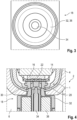
- the charging device 6 has a corresponding mating contact arrangement 18 for galvanic contacting of the charging contact arrangement 1 (see 3 ).
- the charging contact arrangement 1 has a first charging contact 20 and a second charging contact 22, which are used for the conventional transfer of charging energy, specifically a charging current.
- the first charging contact 20 is modeled on a section of a circular ring.
- the second charging contact 22 forms a kind of pin on the center of the annular section.
- a contact surface 24 of the first charging contact 20 is at a different level, i. H. on a different level than a contact surface 26 of the second charging contact 22. Specifically, the contact surface 24 is offset to an outside 28 of the charging contact arrangement 1 and thus also of the hearing aid 4.
- the charging contact arrangement 1 also has a control contact 30 . This is designed in the same way as the first charging contact 20 and, together with this, forms an interrupted circular ring.
- the control contact 30 is electrically isolated from the first charging contact 20 and the second charging contact 22 at least on the outside.
- the mating contact arrangement 18 is shown in more detail.
- This has a first, annular mating contact 32, which is provided for contacting the first charging contact 20, and a second mating contact 34.
- the latter is used for contacting the second charging contact 22 and is in the present embodiment by a kind of "pogo pin", i.e. a spring-loaded pin formed. In the unloaded state, this projects beyond a contact surface 36 of the first mating contact 34 .
- the second charging contact 24 is contacted by the second mating contact 34 .
- the counter-contact arrangement 18 has a holding magnet 38 . This pulls the charging contact arrangement 1 to the mating contact arrangement 18. As a result, the second mating contact 34 is pushed in against the spring action until the first mating contact 32 comes into contact with the first charging contact 20.
- the control contact 30 has a contact surface 40 which is in the same plane, i.e. at the same level, as the contact surface 24 of the first charging contact 20.
- the first mating contact 32 makes contact not only with the first charging contact 20 but also with the control contact 30 and bridges this one.
- the control contact 30 is either connected to the charging controller 16 by means of a tri-state (not shown) in such a way that the control contact 30 has no logic signal in the non-bridged state, or alternatively high-impedance (towards "plus”). in 4 In the bridged state shown, the control contact 30 is recognized as being drawn to a different potential, in the present exemplary embodiment to that of "logical zero".
- the charging controller 16 is set up to recognize from this potential change that the control contact 30 is bridged to the first charging contact 20 and to conclude that the charging contact arrangement 1 is in galvanic contact with the mating contact arrangement 18 . If the charge controller 16 concludes that this Contacting is present, the charging controller 16 switches and keeps the hearing aid 4 in an inactive state in which no signal processing takes place.
- the charging controller 16 is preferably active in order to charge the secondary cell 14 . If the bridging between the control contact 30 and the first charging contact 22 is "lost", the control contact 30, in the case of the tri-state, goes back into its "third” or non-logical state (or alternatively into its high-impedance connected to plus state), whereupon the charging controller 16 activates the hearing aid 4 again.
Landscapes
- Engineering & Computer Science (AREA)
- Physics & Mathematics (AREA)
- Acoustics & Sound (AREA)
- Signal Processing (AREA)
- Health & Medical Sciences (AREA)
- General Health & Medical Sciences (AREA)
- Neurosurgery (AREA)
- Otolaryngology (AREA)
- Computer Networks & Wireless Communication (AREA)
- Charge And Discharge Circuits For Batteries Or The Like (AREA)
Abstract
Description
- Die Erfindung betrifft eine Ladekontaktanordnung für ein Hörvorrichtungssystem. Des Weiteren betrifft die Erfindung ein Hörvorrichtung sowie ein Hörvorrichtungssystem.
- Hörvorrichtungen dienen üblicherweise zur Ausgabe eines Tonsignals an das Gehör des Trägers dieser Hörvorrichtung. Die Ausgabe erfolgt dabei mittels eines Ausgabewandlers, meist auf akustischem Weg über Luftschall mittels eines Lautsprechers (auch als "Hörer" oder "Receiver" bezeichnet). Häufig kommen derartige Hörvorrichtungen dabei als sogenannte Hörhilfegeräte (auch kurz: Hörgeräte) zum Einsatz. Dazu umfassen die Hörvorrichtungen normalerweise einen akustischen Eingangswandler (insbesondere ein Mikrophon) und einen Signalprozessor, der dazu eingerichtet ist, das von dem Eingangswandler aus dem Umgebungsschall erzeugte Eingangssignal (auch: Mikrophonsignal) unter Anwendung mindestens eines üblicherweise nutzerspezifisch hinterlegten Signalverarbeitungsalgorithmus derart zu verarbeiten, dass eine Hörminderung des Trägers der Hörvorrichtung zumindest teilweise kompensiert wird. Insbesondere im Fall eines Hörhilfegeräts kann es sich bei dem Ausgabewandler neben einem Lautsprecher auch alternativ um einen sogenannten Knochenleitungshörer oder ein Cochlea-Implantat handeln, die zur mechanischen oder elektrischen Einkopplung des Tonsignals in das Gehör des Trägers eingerichtet sind. Unter den Begriff Hörvorrichtungen fallen zusätzlich insbesondere auch Geräte wie z.B. sogenannte Tinnitus-Masker, Headsets, Kopfhörer und dergleichen.
- Typische Bauformen von Hörvorrichtungen, insbesondere Hörgeräten, sind Hinter-dem-Ohr- ("BTE"-) und In-dem-Ohr- ("IdO"- oder "ITE"-) Hörvorrichtungen. Diese Bezeichnungen zielen auf die bestimmungsgemäße Trageposition ab. So weisen Hinter-dem-Ohr-Hörvorrichtungen ein (Haupt-) Gehäuse auf, das hinter der Ohrmuschel getragen wird. Hier kann in Modelle unterschieden werden, deren Lautsprecher in diesem Gehäuse angeordnet ist. Die Schallausgabe an das Ohr erfolgt dabei üblicherweise mittels eines Schallschlauchs, der im Gehörgang getragen wird, sowie in Modelle, die einen externen Lautsprecher, der im Gehörgang platziert wird, aufweisen. In-dem-Ohr-Hörvorrichtungen weisen hingegen ein Gehäuse auf, das in der Ohrmuschel oder sogar vollständig im Gehörgang getragen wird.
- Moderne Hörvorrichtungen weisen als Energiequelle häufig integrierte, d. h. fest verbaute Sekundärzellen, also "Akkumulatoren" auf. Zum Wiederaufladen werden neben bspw. USB-Kabeln auch Ladeschalen oder Ladeboxen eingesetzt, die galvanische Ladekontaktsysteme aufweisen. Eine galvanische Kontaktierung hat dabei meist den Vorteil, dass die Umsetzung im Vergleich zu kontaktlosen Ladesystemen einerseits vergleichsweise einfach ist, aber auch häufig mit weniger oder kleiner bauenden Bauelementen auskommt.
- Meist sind die Hörvorrichtungen dazu eingerichtet, während eines Ladevorgangs, also wenn die Hörvorrichtung in der Ladeschale oder -box positioniert und mit den korrespondierenden Kontakten kontaktiert wird, deaktiviert (abgeschaltet) wird. Bei Hörgeräten ist dies unter anderem dahingehend zweckmäßig, um bspw. in einer geschlossenen Ladebox ein Feedback-Geräusch, das durch die Erfassung des eigenen akustischen Ausgabesignals auftritt, zu vermeiden. Meist wird dazu ein Ladestrom oder eine Ladespannung ausgewertet. Wird die Hörvorrichtung aus der Ladeschale oder -box entnommen, aktiviert sich die Hörvorrichtung wieder.
- Der Erfindung liegt die Aufgabe zugrunde, eine besonders sichere Detektion einer Kontaktierung einer Hörvorrichtung mit einem Ladegerät zu ermöglichen.
- Diese Aufgabe wird erfindungsgemäß gelöst durch eine Ladekontaktanordnung mit den Merkmalen des Anspruchs 1. Des Weiteren wird diese Aufgabe erfindungsgemäß gelöst durch eine Hörvorrichtung mit den Merkmalen des Anspruchs 8. Ebenfalls wird diese Aufgabe erfindungsgemäß gelöst durch ein Hörvorrichtungssystem mit den Merkmalen des Anspruchs 9. Vorteilhafte und teils für sich erfinderische Ausführungsformen und Weiterentwicklungen der Erfindung sind in den Unteransprüchen und der nachfolgenden Beschreibung dargelegt.
- Die erfindungsgemäße Ladekontaktanordnung ist zum Einsatz in einem Hörvorrichtungssystem eingerichtet und vorgesehen. Die Ladekontaktanordnung weist dabei einen ersten Ladekontakt auf, der an einer Außenseite (der Ladekontaktanordnung und somit einem diese tragenden Element, bspw. einer Hörvorrichtung) zur Kontaktierung mit einem ersten Gegenkontakt einer Gegenkontaktanordnung zugänglich ist. Außerdem weist die Ladekontaktanordnung einen zweiten Ladekontakt auf, der an der Außenseite zur Kontaktierung mit einem zweiten Gegenkontakt der Gegenkontaktanordnung zugänglich ist. Der erste und der zweite Ladekontakt bilden dabei insbesondere ein zur galvanischen Kontaktierung für einen bestimmungsgemäßen Ladevorgang erforderliches Kontaktpaar ("positiver" und "negativer" Kontakt, konkret zwei unterschiedlichem elektrischen Potential zugeordnete Kontakte). Des Weiteren weist die Ladekontaktanordnung einen Kontrollkontakt auf, der an der Außenseite gegenüber dem ersten und dem zweiten Ladekontakt galvanisch getrennt (angeordnet) ist. Ferner weist die Ladekontaktanordnung auch einen Ladecontroller auf, der dazu eingerichtet ist, bei Überbrückung des Kontrollkontakts auf den ersten Ladekontakt eine Deaktivierung der Hörvorrichtung (des Hörvorrichtungssystems), die dem ersten und zweiten Ladekontakt zugeordnet ist - diese also umfasst oder an diese zum Laden angeschlossen ist -, zu veranlassen.
- Für den bevorzugten Fall, dass die ersten und zweiten Ladekontakte sowie der Kontrollkontakt - mithin die Ladekontaktanordnung - Teil der Hörvorrichtung sind, ist der Ladecontroller mithin dazu eingerichtet, die Hörvorrichtung zu deaktivieren, d. h. insbesondere zumindest eine Audio-Signalverarbeitung abzuschalten.
- Der Ladekontroller schließt anhand der erkannten Überbrückung insbesondere also vorteilhafterweise darauf, dass eine bestimmungsgemäße Kontaktierung des ersten und zweiten Ladekontakts mit dem entsprechenden Gegenkontakt aufgrund der in dem Ladegerät positionierten (oder mit diesem verbundenen) Hörvorrichtung vorliegt. Diese Detektion ist vorteilhafterweise unabhängig von der Stromversorgung des Ladegeräts und somit besonders verlässlich. Die Erfindung ermöglicht vorteilhafterweise somit auch eine besonders verlässliche Steuerung des Hörvorrichtungssystems oder auch nur der Hörvorrichtung. So kann bspw. der Ladevorgang seitens des Ladegeräts (bspw. einer Ladeschale oder einer Ladebox), das vorzugsweise (zumindest für den bestimmungsgemäßen Ladevorgang) einen Teil des Hörvorrichtungssystems bildet, erst dann gestartet werden, wenn die bestimmungsgemäße Kontaktierung erkannt ist. Ebenso kann die Hörvorrichtung vorteilhafterweise verlässlich deaktiviert oder bei Verlust der Kontaktierung wieder aktiviert werden.
- In einer bevorzugten Ausführung ist der Kontrollkontakt derart positioniert, dass dieser im bestimmungsgemäßen Kontaktierungszustand von dem ersten Gegenkontakt kontaktiert ist. Somit überbrückt dieser erste Gegenkontakt den ersten Ladekontakt auf den Kontrollkontakt, verschaltet diese also miteinander. Dadurch braucht kein zusätzlicher, zu dem Kontrollkontakt korrespondierender weiterer Gegenkontakt an der Gegenkontaktanordnung vorgesehen werden. Dies macht wiederum eine "Umkonstruktion" von gegebenenfalls bereits bestehenden Gegenkontaktanordnungen unnötig.
- Weiter bevorzugt weist der Kontrollkontakt eine Kontaktfläche auf, die niveaugleich mit einer Kontaktfläche des ersten Ladekontakts angeordnet ist. Anders ausgedrückt liegen die Kontaktflächen des Kontrollkontakts und des ersten Ladekontakts in der gleichen Ebene. Dadurch wird eine gemeinsame Kontaktierung dieser beiden Kontakte durch den ersten Gegenkontakt vereinfacht.
- Im Gegensatz dazu liegen in einer zweckmäßigen Ausführung die Kontaktflächen des ersten und zweiten Ladekontakts auf unterschiedlichem Niveau. Dadurch kann bspw. eine unbeabsichtigte Kontaktierung des ersten und zweiten Ladekontakts durch denselben Gegenkontakt vermieden werden.
- In einer weiteren zweckmäßigen Ausführung ist der Kontrollkontakt hochohmig beschaltet. Optional kommt hierzu ein sogenannter "Tri-State" zum Einsatz, insbesondere ein digitales Schaltungselement, dessen Ausgänge nicht wie üblich nur zwei ("0" und "1"), sondern zusätzlich noch einen meist mit "Z" oder auch mit "high impedance" (hochohmig) bezeichneten dritten Zustand annehmen können. Alternativ kommen auch Pull-Down- oder Pull-Up-Widerstände zum Einsatz. Optional ist der Kontrollkontakt derart verschaltet, dass dieser im unüberbrückten (also im nicht-kontaktierten) Zustand hochohmig mit dem Ladecontroller verschaltet ist, wohingegen bei einer Überbrückung mittels des ersten Gegenkontakts der Kontrollkontakt auf ein anderes Potential gezogen wird. Insbesondere wenn kein Tri-State zum Einsatz kommt, ist der Kontrollkontakt derart verschaltet, dass letzterer im unüberbrückten Zustand hochohmig, bspw. mit 100 kOhm, gegen "Plus" (also gegen das positive oder höhere Potential, auch "logisch 1") verschaltet ist, auf dem vorzugsweise der zweite Ladekontakt liegt. Wird der Kontrollkontakt auf den ersten Ladekontakt überbrückt, wird der Kontrollkontakt auf "logisch Null" gezogen.
- Der Ladecontroller ist in einer bevorzugten Ausführung dazu eingerichtet, die Überbrückung des Kontrollkontakts auf den ersten Ladekontakt und daran die bestimmungsgemäße Kontaktierung zu erkennen, dass der Kontrollkontakt - insbesondere wie vorstehend beschrieben - auf ein anderes elektrisches Potential, insbesondere das Potential, auf dem auch der erste Ladekontakt liegt, gezogen ist. Dieses Potential ist bspw. davon abhängig, ob zwischen den Gegenkontakten eine Ladespannung (mit einem zugeordneten Ladespannungswert) angelegt ist oder ob der erste Ladekontakt bspw. auf dem Potential der zu ladenden Sekundärzelle (bspw. der Sekundärzelle der Hörvorrichtung) liegt. Somit funktioniert die Erkennung, ob die Kontaktierung mit dem ersten Gegenkontakt vorliegt, unabhängig davon, ob das Ladegerät in Betrieb ist oder inaktiv. Für den Fall, dass die Ladekontaktanordnung der Hörvorrichtung und die Gegenkontaktanordnung dem Ladegerät zugeordnet sind, kann nämlich der Fall eintreten, dass die Hörvorrichtung in das Ladegerät eingesetzt und mit der Gegenkontaktanordnung kontaktiert ist, ohne dass das Ladegerät in Betrieb ist (bspw. nicht an ein Stromnetz angeschlossen oder dergleichen). Da regelmäßig Hörvorrichtungen während des Ladevorgangs deaktiviert werden, kann hier, falls die Deaktivierung nur auf der Detektion der Ladespannung basiert, der Fall eintreten, dass die Hörvorrichtung aktiviert wird und somit die Sekundärzelle entlädt - oder im Fall eines Hörhilfegeräts sogar Feedback-Pfeifen auftritt. Beides kann aufgrund der vorstehend beschriebenen Detektion der Kontaktierung vermieden werden.
- In einer zweckmäßigen Ausführung sind der erste Ladekontakt und der Kontrollkontakt auf einer Kreislinie um den zweiten Ladekontakt angeordnet. Dadurch kann eine rotationssymmetrische Gegenkontaktanordnung eingesetzt werden, die eine einfach herzustellende Kontaktierung zwischen der Ladekontaktanordnung und der Gegenkontaktanordnung ermöglicht.
- In einer bevorzugten Weiterbildung sind die Kontaktflächen des ersten Ladekontakts und des Kontrollkontakts jeweils als Kreisbogenabschnitt ausgebildet. Insbesondere ähneln beide Kontaktflächen gemeinsam betrachtet einem entlang einer Durchmesserlinie aufgetrennten Kreisring.
- Die erfindungsgemäße Hörvorrichtung weist die vorstehend beschriebene Ladekontaktanordnung auf.
- Durch die Deaktivierung bei erkannter Überbrückung ist auch eine Neustart-Funktion der Hörvorrichtung implementiert. Dies ist insbesondere bei modernen Hörvorrichtungen zweckmäßig, die keinen mechanischen "Aus"-Schalter mehr aufweisen. In diesem Fall kann ein Neustart erzwungen werden, wenn die Hörvorrichtung nicht mehr ordnungsgemäß funktioniert und auf die üblichen Eingaben ("Software-Reset") keine Reaktion erfolgt.
- Der Ladecontroller ist dabei vorzugsweise in einen Controller der Hörvorrichtung integriert.
- In optionaler Ausgestaltung ist der Controller und/oder der Ladecontroller zumindest im Kern durch einen Mikrocontroller mit einem Prozessor und einem Datenspeicher gebildet, in dem die Funktionalität zur Erkennung der Kontaktierung in
- Form einer Betriebssoftware (Firmware) programmtechnisch implementiert ist. Alternativ ist der Controller bzw. der Ladecontroller auch durch schaltungstechnische Mittel, optional ein nicht-programmierbares elektronisches Bauteil, z.B. einen ASIC, gebildet.
- Das erfindungsgemäße Hörvorrichtungssystem weist die vorstehend genannte Hörvorrichtung und ein (insbesondere das vorstehend genannte) Ladegerät auf. Die Hörvorrichtung weist mithin (bevorzugt) die Ladekontaktanordnung oder alternativ die Gegenkontaktanordnung und das Ladegerät entsprechend umgekehrt die Gegenkontaktanordnung bzw. die Ladekontaktanordnung auf.
- Mithin teilen die Hörvorrichtung und auch das Hörvorrichtungssystem die Merkmale sowie die sich daraus ergebenden Vorteile mit der Ladekontaktanordnung.
- Die Konjunktion "und/oder" ist hier und im Folgenden insbesondere derart zu verstehen, dass die mittels dieser Konjunktion verknüpften Merkmale sowohl gemeinsam als auch als Alternativen zueinander ausgebildet sein können.
- Nachfolgend wird ein Ausführungsbeispiel der Erfindung anhand einer Zeichnung näher erläutert. Darin zeigen:
- Fig. 1
- in einer Perspektivansicht schematisch eine Ladekontaktanordnung für ein Hörvorrichtungssytem,
- Fig. 2
- in einer Teilschnittdarstellung II-II gemäß
Fig. 1 schematisch die Ladekontaktanordnung, - Fig. 3
- in einer Draufsicht schematisch eine Gegenkontaktanordnung,
- Fig. 4
- in Ansicht gemäß
Fig. 2 schematisch das Hörvorrichtungssystem mit der Ladekontaktanordnung und der Gegenkontaktanordnung in einem bestimmungsgemäßen Kontaktierungszustand, und - Fig. 5
- in einer schematischen Darstellung das Hörvorrichtungssystem.
- Einander entsprechende Teile sind in allen Figuren stets mit gleichen Bezugszeichen versehen.
- In
Fig. 1 und 2 ist schematisch eine Ladekontaktanordnung 1 für ein inFig. 5 schematisch dargestelltes Hörvorrichtungssystem 2 dargestellt. Das Hörvorrichtungssystem 2 weist wenigstens eine Hörvorrichtung in Form eines Hörhilfegeräts (kurz: Hörgerät 4), hier gebildet durch ein hinter dem Ohr zu tragendes Hörgerät, und ein Ladegerät 6 auf. Das Hörgerät 4 weist zwei Mikrophone 8 zur Erfassung von Schall, einen Signalprozessor ("Controller 10") und einen Lautsprecher 12 zur Ausgabe von mittels der Mikrophone 8 erfasst und mittels des Controllers 10 verarbeiteten Ausgangssignalen auf. Zur Energieversorgung weist das Hörgerät 4 eine Sekundärzelle 14 auf. - Die Ladekontaktanordnung 1 ist im dargestellten Ausführungsbeispiel Teil des Hörgeräts 4 und dient zum Eintrag von seitens des Ladegeräts 6 bereitgestellter Ladeenergie in die Sekundärzelle 14. Ein Ladecontroller 16 ist im dargestellten Ausführungsbeispiel Teil des Controllers 10. Das Ladegerät 6 weist entsprechende eine Gegenkontaktanordnung 18 zur galvanischen Kontaktierung der Ladekontaktanordnung 1 auf (s.
Fig. 3 ). - Die Ladekontaktanordnung 1 weist einen ersten Ladekontakt 20 und einen zweiten Ladekontakt 22 auf, die zur herkömmlichen Übertragung der Ladeenergie, konkret eines Ladestroms dienen. Der erste Ladekontakt 20 ist dabei einem Kreisringabschnitt nachgebildet. Der zweite Ladekontakt 22 bildet eine Art Pin auf dem Zentrum des Kreisringabschnitts. Eine Kontaktfläche 24 des ersten Ladekontakts 20 liegt dabei auf einem anderen Niveau, d. h. auf einer anderen Ebene, als eine Kontaktfläche 26 des zweiten Ladekontakts 22. Konkret ist die Kontaktfläche 24 zu einer Außenseite 28 der Ladekontaktanordnung 1 und somit auch des Hörgeräts 4 versetzt.
- Die Ladekontaktanordnung 1 weist außerdem auch einen Kontrollkontakt 30 auf. Dieser ist gleichartig zu dem ersten Ladekontakt 20 ausgebildet und bildet gemeinsam mit diesem einen unterbrochenen Kreisring. Der Kontrollkontakt 30 ist dabei zumindest außenseitig von dem ersten Ladekontakt 20 und dem zweiten Ladekontakt 22 galvanisch getrennt.
- In
Fig. 3 ist die Gegenkontaktanordnung 18 näher dargestellt. Diese weist einen ersten, kreisringförmigen Gegenkontakt 32 auf, der zur Kontaktierung des ersten Ladekontakts 20 vorgesehen ist, sowie einen zweiten Gegenkontakt 34. Letzterer dient zur Kontaktierung des zweiten Ladekontakts 22 und ist im vorliegenden Ausführungsbeispiel durch eine Art "Pogo-Pin", also einen federnd gelagerten Stift gebildet. Dieser steht im unbelasteten Zustand über eine Kontaktfläche 36 des ersten Gegenkontakts 34 über. - In
Fig. 4 ist die bestimmungsgemäße Kontaktierung der Ladekontaktanordnung 1 durch die Gegenkontaktanordnung 18 und das Funktionsprinzip des Kontrollkontakts 30 näher dargestellt. Der zweite Ladekontakt 24 ist durch den zweiten Gegenkontakt 34 kontaktiert. Die Gegenkontaktanordnung 18 weist einen Haltemagneten 38 auf. Dieser zieht die Ladekontaktanordnung 1 zur Gegenkontaktanordnung 18. Dadurch wird der zweite Gegenkontakt 34 gegen die Federwirkung eingeschoben, bis der erste Gegenkontakt 32 mit dem ersten Ladekontakt 20 in Berührung kommt. - Der Kontrollkontakt 30 weist eine Kontaktfläche 40 auf, die in der gleichen Ebene, also auf dem gleichen Niveau liegt, wie die Kontaktfläche 24 des ersten Ladekontakts 20. Dadurch kontaktiert der erste Gegenkontakt 32 nicht nur den ersten Ladekontakt 20 sondern auch den Kontrollkontakt 30 und überbrückt diese somit.
- Der Kontrollkontakt 30 ist entweder mittels eines Tri-State (nicht dargestellt) derart mit dem Ladecontroller 16 verschaltet, dass im nicht-überbrückten Zustand der Kontrollkontakt 30 kein logisches Signal hat, oder alternativ hochohmig (gegen "Plus") verschaltet. Im in
Fig. 4 dargestellten überbrückten Zustand wird der Kontrollkontakt 30 erkanntermaßen auf ein anderes Potential, im vorliegenden Ausführungsbeispiel auf das der "logischen Null", gezogen. Der Ladecontroller 16 ist dabei dazu eingerichtet, aus dieser Potentialänderung zu erkennen, dass der Kontrollkontakt 30 auf den ersten Ladekontakt 20 überbrückt ist, und daraus zu schließen, dass die Ladekontaktanordnung 1 mit der Gegenkontaktanordnung 18 galvanisch kontaktiert ist. Sofern der Ladecontroller 16 den Schluss zieht, dass diese Kontaktierung vorliegt, schaltet und hält der Ladecontroller 16 das Hörgerät 4 in einem inaktiven Zustand, in dem keine Signalverarbeitung erfolgt. Vorzugsweise ist in diesem Zustand lediglich der Ladecontroller 16 aktiv, um die Sekundärzelle 14 zu laden. Geht die Überbrückung zwischen dem Kontrollkontakt 30 und dem ersten Ladekontakt 22 "verloren", geht der Kontrollkontakt 30 im Fall des Tri-State wieder in seinen "dritten" oder nicht logischen Zustand (oder alternativ in seinen hochohmig gegen Plus verschalteten Zustand) über, woraufhin der Ladecontroller 16 das Hörgerät 4 wieder aktiviert. - Der Gegenstand der Erfindung ist nicht auf das vorstehend beschriebene Ausführungsbeispiel beschränkt. Vielmehr können weitere Ausführungsformen der Erfindung von dem Fachmann aus der vorstehenden Beschreibung abgeleitet werden.
-
- 1
- Ladekontaktanordnung
- 2
- Hörvorrichtungssystem
- 4
- Hörgerät
- 6
- Ladegerät
- 8
- Mikrophon
- 10
- Controller
- 12
- Lautsprecher
- 14
- Sekundärzelle
- 16
- Ladecontroller
- 18
- Gegenkontaktanordnung
- 20
- Ladekontakt
- 22
- Ladekontakt
- 24
- Kontaktfläche
- 26
- Kontaktfläche
- 28
- Außenseite
- 30
- Kontrollkontakt
- 32
- Gegenkontakt
- 34
- Gegenkontakt
- 36
- Kontaktfläche
- 38
- Haltemagnet
- 40
- Kontaktfläche
Claims (9)
- Ladekontaktanordnung (1) für ein Hörvorrichtungssystem (2), aufweisend- einen ersten Ladekontakt (20), der an einer Außenseite (28) zur Kontaktierung mit einem ersten Gegenkontakt (32) einer Gegenkontaktanordnung (18) zugänglich ist,- einen zweiten Ladekontakt (22), der an der Außenseite (28) zur Kontaktierung mit einem zweiten Gegenkontakt (34) der Gegenkontaktanordnung (18) zugänglich ist,- einen Kontrollkontakt (30), der an der Außenseite (28) gegenüber dem ersten und dem zweiten Ladekontakt (20, 22) galvanisch getrennt ist, und- einen Ladecontroller (16), der dazu eingerichtet ist, bei Überbrückung des Kontrollkontakts (30) auf den ersten Ladekontakt (20) eine Deaktivierung einer dem ersten und dem zweiten Ladekontakt (20, 22) zugeordneten Hörvorrichtung (4) zu veranlassen.
- Ladekontaktanordnung (1) nach Anspruch 1,
wobei der Kontrollkontakt (30) derart positioniert ist, dass dieser im bestimmungsgemäßen Kontaktierungszustand von dem ersten Gegenkontakt (32) kontaktiert ist. - Ladekontaktanordnung (1) nach Anspruch 2,
wobei der Kontrollkontakt (30) eine Kontaktfläche (40) aufweist, die niveaugleich mit einer Kontaktfläche (24) des ersten Ladekontakts (20) angeordnet ist. - Ladekontaktanordnung (1) nach einem der Ansprüche 1 bis 3,
wobei der Kontrollkontakt (30) hochohmig beschaltet ist. - Ladekontaktanordnung (1) nach Anspruch 2 und 4,
wobei der Ladecontroller (16) dazu eingerichtet ist, die Überbrückung des Kontrollkontakts (30) auf den ersten Ladekontakt (20) daran zu erkennen, dass der Kontrollkontakt (30) auf ein anderes elektrisches Potential, insbesondere das Potential, auf dem auch der erste Ladekontakt (20) liegt, gezogen ist. - Ladekontaktanordnung (1) nach einem der Ansprüche 1 bis 5,
wobei der erste Ladekontakt (20) und der Kontrollkontakt (30) auf einer Kreislinie um den zweiten Ladekontakt (22) angeordnet sind. - Ladekontaktanordnung (1) nach Anspruch 6,
wobei die Kontaktflächen (24, 40) des ersten Ladekontakts (20) und des Kontrollkontakts (30) jeweils als Kreisbogenabschnitt ausgebildet sind. - Hörvorrichtung (4) mit einer Ladekontaktanordnung (1) gemäß einem der Ansprüche 1 bis 7.
- Hörvorrichtungssystem (2) aufweisend ein Hörvorrichtung (4) und ein Ladegerät (6), wobei die Hörvorrichtung (4) eine Ladekontaktanordnung (1) gemäß einem der Ansprüche 1 bis 7 oder eine korrespondierende Gegenkontaktanordnung (18) und das Ladegerät (6) entsprechend umgekehrt die Gegenkontaktanordnung (18) bzw. die Ladekontaktanordnung (1) umfassen.
Applications Claiming Priority (1)
| Application Number | Priority Date | Filing Date | Title |
|---|---|---|---|
| DE102021213958.2A DE102021213958B4 (de) | 2021-12-08 | 2021-12-08 | Ladekontaktanordnung, Hörvorrichtung und Hörvorrichtungssystem |
Publications (1)
| Publication Number | Publication Date |
|---|---|
| EP4195703A1 true EP4195703A1 (de) | 2023-06-14 |
Family
ID=84330964
Family Applications (1)
| Application Number | Title | Priority Date | Filing Date |
|---|---|---|---|
| EP22206533.6A Pending EP4195703A1 (de) | 2021-12-08 | 2022-11-10 | Ladekontaktanordnung, hörvorrichtung und hörvorrichtungssystem |
Country Status (4)
| Country | Link |
|---|---|
| US (2) | US12238485B2 (de) |
| EP (1) | EP4195703A1 (de) |
| CN (1) | CN219536310U (de) |
| DE (1) | DE102021213958B4 (de) |
Citations (3)
| Publication number | Priority date | Publication date | Assignee | Title |
|---|---|---|---|---|
| EP1973375A2 (de) * | 2007-03-20 | 2008-09-24 | Siemens Audiologische Technik GmbH | Hörvorrichtung mit spezieller Ladeschaltung |
| DE102014218053A1 (de) * | 2014-09-10 | 2016-03-10 | Sivantos Pte. Ltd. | Hörinstrument mit Stromversorgungseinheit und Stromversorgungseinheit für ein Hörinstrument |
| WO2017212052A1 (de) * | 2016-06-10 | 2017-12-14 | Sivantos Pte. Ltd. | Hörgerät und bausatz für ein hörgerät |
Family Cites Families (2)
| Publication number | Priority date | Publication date | Assignee | Title |
|---|---|---|---|---|
| DE102012214469A1 (de) | 2012-06-06 | 2013-12-12 | Siemens Aktiengesellschaft | Hörinstrumentsystem mit wiederaufladbarer Batterie |
| CN217135694U (zh) * | 2022-03-21 | 2022-08-05 | 安徽华米信息科技有限公司 | 充电系统、充电盒及助听器 |
-
2021
- 2021-12-08 DE DE102021213958.2A patent/DE102021213958B4/de active Active
-
2022
- 2022-11-10 EP EP22206533.6A patent/EP4195703A1/de active Pending
- 2022-12-06 US US18/075,587 patent/US12238485B2/en active Active
- 2022-12-06 CN CN202223264019.6U patent/CN219536310U/zh active Active
-
2024
- 2024-10-16 US US18/916,947 patent/US20250039617A1/en active Pending
Patent Citations (3)
| Publication number | Priority date | Publication date | Assignee | Title |
|---|---|---|---|---|
| EP1973375A2 (de) * | 2007-03-20 | 2008-09-24 | Siemens Audiologische Technik GmbH | Hörvorrichtung mit spezieller Ladeschaltung |
| DE102014218053A1 (de) * | 2014-09-10 | 2016-03-10 | Sivantos Pte. Ltd. | Hörinstrument mit Stromversorgungseinheit und Stromversorgungseinheit für ein Hörinstrument |
| WO2017212052A1 (de) * | 2016-06-10 | 2017-12-14 | Sivantos Pte. Ltd. | Hörgerät und bausatz für ein hörgerät |
Also Published As
| Publication number | Publication date |
|---|---|
| US20250039617A1 (en) | 2025-01-30 |
| US20230179931A1 (en) | 2023-06-08 |
| DE102021213958A1 (de) | 2023-06-15 |
| DE102021213958B4 (de) | 2025-04-03 |
| CN219536310U (zh) | 2023-08-15 |
| US12238485B2 (en) | 2025-02-25 |
Similar Documents
| Publication | Publication Date | Title |
|---|---|---|
| EP2028880B1 (de) | Automatische Hörer-Typ-Erkennung bei Hörhilfegeräten | |
| EP1973375A2 (de) | Hörvorrichtung mit spezieller Ladeschaltung | |
| EP2200346B1 (de) | Hörvorrichtung mit automatischer Algorithmenumschaltung | |
| DE102014218053B4 (de) | Hörinstrument mit Stromversorgungseinheit und Stromversorgungseinheit für ein Hörinstrument | |
| DE102009033898B3 (de) | Ladegerät für ein Hörgerät mit elastischen Kontakten | |
| EP2991378A1 (de) | Hörhilfegerät sowie verfahren zum betrieb des hörhilfegeräts mit einer kommunikationsvorrichtung | |
| DE102021213958B4 (de) | Ladekontaktanordnung, Hörvorrichtung und Hörvorrichtungssystem | |
| DE102008024515B3 (de) | Hörhilfe und Anordnung | |
| DE102005006404B3 (de) | Modulares Hörgerätesystem | |
| EP2574083A2 (de) | IDO-Hörinstrument mit Programmierbuchse | |
| WO2016038165A1 (de) | Hörinstrument und verfahren zum betrieb eines hörinstruments | |
| EP2026602B1 (de) | Hörvorrichtung mit beweglichem Ladekontakt | |
| DE102020209507A1 (de) | Verfahren zur Überprüfung von Hörgerätefunktionen, Ladebox für ein Hörgerät und Hörgerät | |
| DE102019207680B3 (de) | Hörgerät, Receivereinheit sowie Verfahren zum Betrieb eines Hörgerätes | |
| DE102007054603B4 (de) | Hörvorrichtung mit gesteuerter Programmierbuchse | |
| EP3469815B1 (de) | Elektronikrahmen zur halterung von elektronischen komponenten eines hörgeräts, hörgerät und bausatz für ein hörgerät | |
| DE102023207237A1 (de) | Verfahren zum Betrieb eines induktiven Ladegeräts eines Hörgeräts und induktives Ladegerät eines Hörgeräts | |
| WO2023052436A1 (de) | Magnetischer steckverbinder für einen galvanischen ladeanschluss eines elektronischen geräts, insbesondere eines hörinstruments | |
| EP2897377A1 (de) | HdO-Hörinstrument mit Gehäuse und Schallschlauch | |
| EP3697103B1 (de) | Hörinstrumentesystem mit platzsparendem batterieladeanschluss | |
| DE102021209822B3 (de) | Verfahren zum Betrieb eines Hörgeräts | |
| EP3863306A1 (de) | Hörsystem mit mindestens einem im oder am ohr des nutzers getragenen hörinstrument sowie verfahren zum betrieb eines solchen hörsystems | |
| EP4572337A1 (de) | Hörinstrument und verfahren zum betrieb eines solchen | |
| WO2012019636A1 (de) | Verfahren zum betreiben eines hörgeräts und entsprechendes hörgerät | |
| DE102013210170B4 (de) | Modulare Hörgerätegehäusevorrichtung für Hörgeräte |
Legal Events
| Date | Code | Title | Description |
|---|---|---|---|
| PUAI | Public reference made under article 153(3) epc to a published international application that has entered the european phase |
Free format text: ORIGINAL CODE: 0009012 |
|
| STAA | Information on the status of an ep patent application or granted ep patent |
Free format text: STATUS: THE APPLICATION HAS BEEN PUBLISHED |
|
| AK | Designated contracting states |
Kind code of ref document: A1 Designated state(s): AL AT BE BG CH CY CZ DE DK EE ES FI FR GB GR HR HU IE IS IT LI LT LU LV MC ME MK MT NL NO PL PT RO RS SE SI SK SM TR |
|
| STAA | Information on the status of an ep patent application or granted ep patent |
Free format text: STATUS: REQUEST FOR EXAMINATION WAS MADE |
|
| 17P | Request for examination filed |
Effective date: 20231214 |
|
| RBV | Designated contracting states (corrected) |
Designated state(s): AL AT BE BG CH CY CZ DE DK EE ES FI FR GB GR HR HU IE IS IT LI LT LU LV MC ME MK MT NL NO PL PT RO RS SE SI SK SM TR |
|
| STAA | Information on the status of an ep patent application or granted ep patent |
Free format text: STATUS: EXAMINATION IS IN PROGRESS |
|
| 17Q | First examination report despatched |
Effective date: 20250508 |