EP4195645B1 - Verfahren zur spektralen farbdichtemessung im farbdruck - Google Patents
Verfahren zur spektralen farbdichtemessung im farbdruck Download PDFInfo
- Publication number
- EP4195645B1 EP4195645B1 EP21213370.6A EP21213370A EP4195645B1 EP 4195645 B1 EP4195645 B1 EP 4195645B1 EP 21213370 A EP21213370 A EP 21213370A EP 4195645 B1 EP4195645 B1 EP 4195645B1
- Authority
- EP
- European Patent Office
- Prior art keywords
- color
- spectral
- measuring
- colour
- measurement
- Prior art date
- Legal status (The legal status is an assumption and is not a legal conclusion. Google has not performed a legal analysis and makes no representation as to the accuracy of the status listed.)
- Active
Links
Images

Classifications
-
- H—ELECTRICITY
- H04—ELECTRIC COMMUNICATION TECHNIQUE
- H04N—PICTORIAL COMMUNICATION, e.g. TELEVISION
- H04N1/00—Scanning, transmission or reproduction of documents or the like, e.g. facsimile transmission; Details thereof
- H04N1/46—Colour picture communication systems
- H04N1/56—Processing of colour picture signals
- H04N1/60—Colour correction or control
- H04N1/603—Colour correction or control controlled by characteristics of the picture signal generator or the picture reproducer
- H04N1/6033—Colour correction or control controlled by characteristics of the picture signal generator or the picture reproducer using test pattern analysis
- H04N1/6036—Colour correction or control controlled by characteristics of the picture signal generator or the picture reproducer using test pattern analysis involving periodic tests or tests during use of the machine
-
- G—PHYSICS
- G01—MEASURING; TESTING
- G01J—MEASUREMENT OF INTENSITY, VELOCITY, SPECTRAL CONTENT, POLARISATION, PHASE OR PULSE CHARACTERISTICS OF INFRARED, VISIBLE OR ULTRAVIOLET LIGHT; COLORIMETRY; RADIATION PYROMETRY
- G01J3/00—Spectrometry; Spectrophotometry; Monochromators; Measuring colours
- G01J3/46—Measurement of colour; Colour measuring devices, e.g. colorimeters
- G01J3/50—Measurement of colour; Colour measuring devices, e.g. colorimeters using electric radiation detectors
-
- B—PERFORMING OPERATIONS; TRANSPORTING
- B41—PRINTING; LINING MACHINES; TYPEWRITERS; STAMPS
- B41J—TYPEWRITERS; SELECTIVE PRINTING MECHANISMS, i.e. MECHANISMS PRINTING OTHERWISE THAN FROM A FORME; CORRECTION OF TYPOGRAPHICAL ERRORS
- B41J2/00—Typewriters or selective printing mechanisms characterised by the printing or marking process for which they are designed
- B41J2/005—Typewriters or selective printing mechanisms characterised by the printing or marking process for which they are designed characterised by bringing liquid or particles selectively into contact with a printing material
- B41J2/01—Ink jet
- B41J2/21—Ink jet for multi-colour printing
- B41J2/2107—Ink jet for multi-colour printing characterised by the ink properties
-
- B—PERFORMING OPERATIONS; TRANSPORTING
- B41—PRINTING; LINING MACHINES; TYPEWRITERS; STAMPS
- B41J—TYPEWRITERS; SELECTIVE PRINTING MECHANISMS, i.e. MECHANISMS PRINTING OTHERWISE THAN FROM A FORME; CORRECTION OF TYPOGRAPHICAL ERRORS
- B41J29/00—Details of, or accessories for, typewriters or selective printing mechanisms not otherwise provided for
-
- H—ELECTRICITY
- H04—ELECTRIC COMMUNICATION TECHNIQUE
- H04N—PICTORIAL COMMUNICATION, e.g. TELEVISION
- H04N1/00—Scanning, transmission or reproduction of documents or the like, e.g. facsimile transmission; Details thereof
- H04N1/46—Colour picture communication systems
- H04N1/56—Processing of colour picture signals
- H04N1/60—Colour correction or control
- H04N1/603—Colour correction or control controlled by characteristics of the picture signal generator or the picture reproducer
- H04N1/6033—Colour correction or control controlled by characteristics of the picture signal generator or the picture reproducer using test pattern analysis
- H04N1/6041—Colour correction or control controlled by characteristics of the picture signal generator or the picture reproducer using test pattern analysis for controlling uniformity of color across image area
Definitions
- the invention relates to a method for spectral color density measurement in color printing.
- the method mentioned concerns the field of densitometry in general and spectral densitometry in particular.
- Densitometry is a method for controlling the printing process in terms of solid density and tonal values. It works reliably for black and white prints and for prints with the process colors cyan (blue), magenta, yellow and key (black).
- the printing ink to be measured is illuminated by a light source.
- the light beam penetrates the translucent (glazing) ink layer and is weakened in the process.
- the remaining light is scattered by the paper base. Part of this scattered light passes through the ink layer again and is further weakened.
- the remaining light finally reaches the measuring device, which converts the light into electrical energy.
- the result of incident light densitometry is given in density units.
- the color density of a printing ink depends primarily on the type of pigment, its concentration and the thickness of the ink layer. For a given printing ink, the color density is a measure of the layer thickness.
- color filters are used in the beam path that are adapted to the absorption behavior of the colors cyan, magenta and yellow.
- the printing ink is still wet and has a glossy surface. When drying, the ink soaks into the paper and loses its shine. This changes not only the color tone of the ink, but also the color density value. If the still wet printing medium is to be compared densitometrically with the generally dry target values, this is only possible to a limited extent.
- Polarization filters allow only one direction of oscillation of the light waves oscillating in all directions to pass through.
- the light rays directed through the first polarization filter are partially reflected by the color surface. Their direction of oscillation does not change.
- the second polarization filter is rotated 90° relative to the first so that these reflected light waves are not allowed through.
- the reflectance ⁇ represents the ratio LeP / LeW.
- LeP is the reflectance of the measured printing ink and LeW is the reflectance of the reference white.
- D can therefore also be represented as log LeW/LeP.
- the reflectance ß indicates the ratio between the light reflections of a sample to be measured (printing ink) and a white (reference value).
- the reflectance ⁇ is often also referred to as the reflectance factor P ⁇ .
- Spectral densitometry uses the measurement principle of spectral reflectance, from which all other colorimetric and densitometric quantities can be calculated.
- the spectrodensitometer sensor is sensitive to large parts, especially the entire visible range of the electromagnetic spectrum, i.e. all wavelengths of visible light.
- the sensitivity range begins at around 380 nm in violet and extends through the color nuances blue-green, green and yellow to red at around 730 nm.
- the spectral reflectance values are measured for all wavelength sections (bands) simultaneously using a polychromator or spectral measuring head.
- the bands each cover wavelength ranges with a specified width.
- polychromators are known that can resolve bands with a width between 10 and 50 nm.
- the light is spread out using a diffraction grating, a prism or many narrow-band filters.
- the measured luminous flux is divided into its spectral components, the signal strengths of which are measured and output as a whole as a spectral value curve.
- spectral measurement uses spectral color information to calculate the color layers.
- the color densities for cyan, magenta, yellow and other colors can be determined from the spectral measurement values without the need for separate measurements with different color filters.
- spectral densitometers In spectral densitometers, photosensitive sensors scan the entire visible range of the electromagnetic spectrum to determine the spectral reflectance values when determining the densitometric quantities. Physical filters can be inserted into the beam path, as well as virtual, i.e. mathematically simulated filters. In addition, standard-compliant density measurement requires the use of a polarization filter mentioned above, which suppresses the differences in gloss between wet and already dried ink layers. In this way, the measurements are made comparable regardless of how close the printing process was.
- hand-held measuring devices for individual measurements hand-held scanning devices for manually recording measuring fields arranged in a line and electromotor-driven scanning measuring devices are used as scanning spectrodensitometers.
- inline measuring systems are known that are arranged in a printing system and measure printed measuring fields one after the other. These devices have the common feature that the remission spectrum is spectrally recorded at one location on the printed image to be measured using an optic and a sensor arrangement.
- the dimensions of the recorded, preferably round, area are in the order of 1 to 10 mm.
- the color measurement fields printed on the printing medium are usually rectangular or square. Color gradients are printed for each of the printer's primary colors in gradations from 100% to 0% in steps of, for example, 10%, whose color densities are then spectrally determined using one of the measuring devices described.
- the area of each color measurement field is not completely recorded by the optics of the measuring device, since the area observed by the optics is usually round. This means that the corners of the measuring fields are not recorded. In addition, only one value for the color density is determined for the measured area.
- a color measurement system ACMS TM - Advanced Color Measurement System
- ICMS TM - Inline Color Measurement System inline color measurement system
- the system has a spectral scanner, possibly arranged inline, which can be used for different substrates, i.e. printing media or materials (paper, film, wood, plastic, ceramic, mineral) and different printing processes (digital printing, in particular inkjet printing or laser printing, as well as gravure printing, flexographic printing, offset printing or screen printing).
- the ICMS TM and the ACMS TM use a spectral, spatially resolved scanning technology to measure a printed image.
- the spectral measurement system is, for example, a multispectral camera with a plurality of wavelength bands, preferably with 36 wavelength bands per recorded image point, which generates color information per wavelength band. This creates a color spectrum from the wavelength bands for each recorded image point (pixel).
- a common sensor technology consists of providing individual pixels on a CMOS sensor with different color filters so that a plurality of spectral information from a recorded image area can be recorded with one image recording.
- the spectral measurement system can also be a hyperspectral camera, in which the light is spectrally split per pixel using an optical device, for example a prism, and individual spectral ranges are measured separately. This increases the spectral resolution compared to a multispectral camera, for example to up to 350 or more wavelength bands.
- a scanner resolution of at least 32 dpi, preferably at least 72 dpi, particularly preferably at least 90 dpi can be achieved.
- the DE 10 2009 012 815 A1 discloses a measuring device with a movable measuring device in a printing machine, wherein the measuring device is a spectral scanner with a resolution of 100 or 200 dpi.
- the spectral scanner is used for color measurement and color calibration.
- the US 2007/0002344 A1 describes a calibration system for a printer that uses a color density measuring unit in the form of either a spectrometer or an RGB scanner.
- the US 2002/0104457 A1 discloses a spectral measurement using a conventional spectrometer to measure the pressure at predetermined locations and determine the spectral reflectance factor.
- the object of the present invention is to improve the spectral color density measurement in color printing.
- the procedure for spectral color density measurement in color printing comprises the following steps: First, a spectrally resolved reference reflectance is measured for an unprinted substrate using a spatially resolved spectral measuring system, preferably at a large number of measuring points. This reflectance is required to standardize the reflectances to be measured later.
- the reference measurement can be carried out before printing on the substrate and, if necessary, continuously during the printing process. To do this, unprinted sections of the substrate must be left free at specified positions during the printing process. Printing media or materials in the form of paper, film, wood, plastic, ceramic, mineral or other materials are used as substrates, for example.
- a color printer is used to print at least one color measuring field, preferably a plurality of color measuring fields, with at least one printing color.
- a printing ink is generally understood to be a mixture containing colorants that is transferred to a substrate such as paper or plastic using a printer.
- Digital color printers in particular use three printing inks: cyan, magenta and yellow, and possibly black (key).
- other printing inks with different pigment compositions can also be used.
- color printing processes for example digital printing, particularly inkjet printing or laser printing, as well as gravure printing, flexographic printing, offset printing or screen printing.
- inkjet printers the printing inks are designed as inks, while in laser printers they are designed as toners.
- different printing ink formulations based on water, oils or solvents are used as printing inks.
- a colour measuring field of one printing colour is sufficient, but so-called colour wedges are usually printed for each of the printing colours, which contain a number of colour density-graded areas for each printing colour.
- the spectrally resolved reflectance for at least one color measuring field is then measured at a large number of measuring points using the spatially resolved spectral measuring system.
- Spectrally resolved color measurements are thus carried out distributed over at least a partial area of the color measuring field, preferably over the entire color measuring field.
- the measuring system has either a line sensor or a two-dimensional sensor of a hyperspectral camera.
- the sensor has a large number of pixels, for each of which a spectrum is recorded. This achieves sufficiently high resolutions to measure the various color measuring fields at a large number of measuring points. This achieves a spectral resolution of preferably 36 or up to 350 or more wavelength bands. A resolution in the range of 10 nm, in particular in the range of 1 to 30 nm, is then achieved for each wavelength band. This covers the visible spectrum of light between 380 and 730 nm.
- a color density for the printing ink is calculated from the spectral distribution of the measured reflectance, the measured reference reflectance and a spectral weighting function representing the printing ink.
- the preferred procedure is the standards ISO 13655 Chapter 5 and ISO 5.3 Chapter 4.5.2 together with Annex B.
- ISO 5.3 Annex B defines that depending on the width of the spectral channels, for a width or interval of 1 nm, the calculation is carried out according to equation B.1 in Annex B.3 and for channel widths or intervals of 10 or 20 nm the calculation is carried out according to equation B.2.
- the spectral reflectance is multiplied by the weighting function, divided by a normalization factor and summed over all wavelengths.
- each measured spectral reflectance for each measuring point within each color measuring field results in a value for the color density.
- the measuring system can be arranged as an inline measuring device in the area of the printer or used as an offline device for subsequent measurement of the printed surface.
- the color measuring system is aligned and moved relative to the at least one color measuring field such that the at least one color measuring field is measured in a grid pattern at a plurality of measuring points with a resolution of at least 30 dpi, preferably of at least 70, in particular of at least 90 dpi.
- An upper limit is, for example, in the range of 250 dpi.
- the line sensor or the two-dimensional sensor is aligned perpendicular to the direction of movement relative to the printed substrate so that the resulting measurement grid runs in an alignment in the direction of movement. Traversing, with simultaneous 90° rotation of the color measuring system, transverse to the actual direction of movement is equally permissible.
- the method is designed such that the area of the at least one color measuring field is measured to at least 80%, preferably to at least 90%, in particular to at least 95%.
- the color measuring field is measured almost completely, in particular completely, and the color densities determined enable a more precise analysis of the color density distribution, i.e. the print result over the area of the color measuring field.
- the color densities are averaged for at least two measuring points, preferably a plurality of measuring points and in particular for all measuring points of each color measuring field.
- the large number of measuring points thus allows an accurate and at the same time variable evaluation of the color measuring field.
- a group of color nozzles of a print head is assigned to each measuring point of the raster-shaped spectral color density measurement of the at least one color measuring field.
- the group of color nozzles has a maximum of 10 color nozzles, preferably a maximum of 5 color nozzles, in particular one color nozzle.
- a print head typically has a width of 40-50 mm and the color printer then has a plurality of print heads that achieve a total printing width of approx. 1000 mm.
- the process is carried out with a specified lighting of the surface to be printed or the surface being printed.
- the choice of lighting follows the requirements of ISO standard 13655, in particular the measurement condition M3.
- the standardized lighting type D50 is preferably used.
- Polarization filters can also be arranged in the beam path to enable wet print images to be measured.
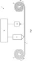
- Fig. 1 shows a schematic of a first system 2 for carrying out the method for spectral color density measurement in color printing.
- the carrier material 4 is unrolled from a first roll 6, guided underneath the color printer 8 and the spectral measuring system 10 and then rolled up again on a roll 12.
- the endless carrier material 4 has a finite but large length.
- the spectral measuring system is shown in a simplified manner and is explained using the example of the Fig. 4 explained in more detail.
- the color printer 8 is designed as a digital inkjet printer, with which the surface of the substrate is printed in the inline process shown. Inkjet printers are preferred for this application, but the invention is not limited to the use of inkjet printers.
- the results of the spectral measurements by the spectral measuring system are transmitted to a control device 14, which evaluates the recorded spectral data.
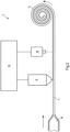
- Fig. 2 shows a schematic of a second system 2 for carrying out the method for spectral color density measurement in color printing.
- the carrier material 4 is not unwound from a roll, but is produced by an extrusion process.
- an extrusion tool 16 is shown schematically, from which a strand is extruded to produce, for example, an edge material for use in furniture panels. Basically necessary calenders and cooling stations are not shown here for the sake of simplicity.
- a continuous casting device can also be used to produce a continuous strand of carrier material.
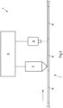
- Fig. 3 shows schematically a third system 2 for carrying out the method for spectral color density measurement in color printing.
- the carrier material 4 is not designed as a continuous material, but consists of a large number of elements 18 that abut one another, for example plates or sheets.
- the carrier material 4 therefore consists of individual elements 18 that are separate before and after printing.
- the continuous printing and measuring of color charts then takes place on the carrier material 4 composed of individual elements 18.
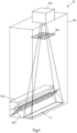
- Fig. 4 shows an embodiment of a spectral measuring system 10 for carrying out a method according to the invention.
- the measuring system 10 initially has a housing 10.1 in which the components are arranged.
- An illumination device 10.2 is arranged in the housing 10.1, which illuminates a scanning area 4.1 on the surface of the carrier material 4.
- Light of a standardized type of illumination, for example D50, is generated with a predetermined spectral intensity distribution over the visible spectral range from 380 to 730 nm.
- a first polarization filter 10.3 is arranged in the beam path in front of the scanning area, which polarizes the incoming light before it hits the scanning area 4.1.
- the light reflected by the scanning area 4.1 then runs in the direction of a second polarization filter 10.4.
- the first polarization filter 10.3 only allows one direction of vibration of the light waves oscillating in all directions to pass through.
- the light rays directed by the first polarization filter 10.3 are partially reflected in a specular manner by the color surface in the scanning area 4.1, particularly if the surface is still wet from a printing process that took place shortly before, or at least has not yet dried out. In the case of a specular reflection, the direction of vibration of the light does not change.
- the second polarization filter 10.4 is arranged rotated by 90° with respect to the first polarization filter, so that the light waves reflected by the scanning area 4.1 are not allowed through.
- the polarization filters described can also be omitted.
- the measuring and evaluation device 10.5 is arranged in the beam path behind the second polarization filter 10.4.
- a common sensor technology consists of providing individual pixels on a CMOS sensor with different color filters, so that a plurality of spectral information from a recorded image area can be recorded with one image recording.
- the spectral measurement system can also comprise a hyperspectral camera, which has an increased spectral resolution compared to a multispectral camera, for example up to 350 or more wavelength bands per measurement point.
- the spectral information is then preferably evaluated within the spectral measurement system using data processing.
- the method according to the invention for spectral color density measurement in color printing can then be carried out with a Fig. 1 to 4 shown system 2 with spectral measuring system 10 as follows.
- a spectrally resolved reference reflectance is measured at a large number of measuring points for a substrate 4 that is not yet printed using the spatially resolved spectral measuring system 10.
- the color printer is controlled in such a way that specified sections of the surface of the substrate 4 remain unprinted. This can be done in an inline process at the beginning of the print or at specified intervals during the printing process. As can be seen from the Fig. 5 As explained, color wedges often also have unprinted areas that can also be used to measure the reference reflectance.
- the measured spectral reference reflectances are stored for later recurring standardization when determining the color density D.
- the spectral measuring system 10 is used to measure spectrally resolved reflectances for the color measuring fields at a large number of measuring points and for each measuring point a color density for the printing ink is calculated from the spectral distribution of the measured reflectance, the measured reference reflectance and a spectral weighting function representing the printing ink.
- Fig. 5 shows schematically a section of a substrate 20, which is formed by one of the previously described carrier materials 4.
- color wedges marked overall with 22, have been printed as a sequence of color measuring fields 24 for the four printing colors black (Key -K), yellow (Y), magenta (M) and cyan (C), the printing of which with the respective printing color is shown in the illustration according to Fig. 5 from top to bottom from 100% to 0% in equal steps.
- the color measurement fields are then spectrally measured using the method described below and the color density is determined from the measured values.
- Fig. 5 shows, the temporal pressure progression runs from top to bottom, as does the subsequent measurement.
- the spectrally resolved reflectance for the color measuring fields 24 is measured with the spatially resolved spectral measuring system 10 at a plurality of measuring points 26 within each of the color measuring fields 24, as in Fig. 5 (a) shown with a line grid.
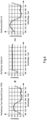
- Fig. 6 and 7 show in a graphical manner the application of the calculation of the colour density for a colour measurement field of the primary colour cyan according to the ISO 5.3 standard according to Annex B and in particular according to Annex B.4.
- D ⁇ log ⁇ ⁇ W ⁇ ⁇ R ⁇ 100
- W ⁇ is the spectral weighting factor of the wavelength ⁇
- R ⁇ is the spectral reflectance factor of the wavelength ⁇
- 100 is the sum of the spectral weighting factors over the wavelength range from 380 nm to 730 nm.
- Fig. 6 first shows the calculation of the spectral distribution of the reflectance factor R ⁇ as a quotient of the spectral distribution of the reflectance of the color measuring field and the spectral distribution of the reflectance of the unprinted substrate. Instead of mathematical expressions, corresponding spectra are shown. For equal values of the wavelength ⁇ , the corresponding values are then divided by each other. As a result, a spectral distribution of the reflectance factor R ⁇ dependent on the wavelength ⁇ is calculated.
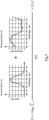
- Fig. 7 shows in an equally clear manner how the colour density D is calculated as a negative logarithm to the base 10 of the sum over all wavelengths ⁇ via the products of the spectral distribution of the weighting factor W ⁇ for cyan and the spectral distribution of the reflectance factor R ⁇ for each value of ⁇ divided by 100.
- the result is a value for the colour density D of 0.42.
- the at least one color measuring field is measured in a raster format at a large number of measuring points.
- a resolution of at least 30 dpi, preferably of at least 70, in particular of at least 90 dpi can be achieved.
- Fig. 5 (b) shows the situation as it is known from the state of the art.
- the circle 28 shown indicates the area covered by a known color densitometer, which uses its optical system to cover the color measurement field within the circle 28 with a spectral measurement curve.
- the color measurement field was therefore not only covered in less detail, but the area of the color measurement field was also only measured inadequately.
- the color densities of all measuring points within a color measuring field measured according to the described method can be evaluated in various ways.
- the color densities can be averaged for at least two measuring points, preferably a plurality of measuring points and in particular for all measuring points of each color measuring field. In this way, average values can be calculated for individual groups of measuring points or even for all measuring points.
- each measuring point 26 of the raster-shaped spectral color density measurement of the at least one color measuring field 24 can be assigned to a group of color nozzles of a print head of the color printer.
- Information on the individual groups of color nozzles can thus be derived from the spectral color density measurements, which enable an assessment of the functionality of the groups of color nozzles.
- the group of color nozzles can have a maximum of 10 color nozzles, preferably a maximum of 5 color nozzles, in particular one color nozzle.
- the pattern to be printed in each of the printing colors is introduced as depressions in the roller surfaces.
- the depressions can be as small as 50 ⁇ m and are also referred to as a dashed roller.
- systematic deviations in the print quality can occur, which are included in the average spectral measurement value in an integral measurement of the entire color measuring field.
- average values can be calculated over all measuring points and measuring points with too large a systematic deviation from the average value can be disregarded when recalculating the average value of the spectral information. This improves the determination of the spectral information compared to an individual measurement according to the state of the art.
Landscapes
- Physics & Mathematics (AREA)
- Spectroscopy & Molecular Physics (AREA)
- Engineering & Computer Science (AREA)
- Multimedia (AREA)
- Signal Processing (AREA)
- General Physics & Mathematics (AREA)
- Spectrometry And Color Measurement (AREA)
Priority Applications (6)
| Application Number | Priority Date | Filing Date | Title |
|---|---|---|---|
| EP21213370.6A EP4195645B1 (de) | 2021-12-09 | 2021-12-09 | Verfahren zur spektralen farbdichtemessung im farbdruck |
| ES21213370T ES2994701T3 (en) | 2021-12-09 | 2021-12-09 | Method for spectral ink density measurement in colour printing |
| PL21213370.6T PL4195645T3 (pl) | 2021-12-09 | 2021-12-09 | Sposób pomiaru widmowego gęstości barwy w druku kolorowym |
| US18/717,576 US20250052618A1 (en) | 2021-12-09 | 2022-12-08 | Method for Spectral Colour Density Measurement in Colour Printing |
| CN202280081688.3A CN118743211A (zh) | 2021-12-09 | 2022-12-08 | 用于在彩色印刷中进行光谱式色密度测量的方法 |
| PCT/EP2022/084983 WO2023104966A1 (de) | 2021-12-09 | 2022-12-08 | Verfahren zur spektralen farbdichtemessung im farbdruck |
Applications Claiming Priority (1)
| Application Number | Priority Date | Filing Date | Title |
|---|---|---|---|
| EP21213370.6A EP4195645B1 (de) | 2021-12-09 | 2021-12-09 | Verfahren zur spektralen farbdichtemessung im farbdruck |
Publications (3)
| Publication Number | Publication Date |
|---|---|
| EP4195645A1 EP4195645A1 (de) | 2023-06-14 |
| EP4195645B1 true EP4195645B1 (de) | 2024-10-02 |
| EP4195645C0 EP4195645C0 (de) | 2024-10-02 |
Family
ID=78844906
Family Applications (1)
| Application Number | Title | Priority Date | Filing Date |
|---|---|---|---|
| EP21213370.6A Active EP4195645B1 (de) | 2021-12-09 | 2021-12-09 | Verfahren zur spektralen farbdichtemessung im farbdruck |
Country Status (6)
| Country | Link |
|---|---|
| US (1) | US20250052618A1 (pl) |
| EP (1) | EP4195645B1 (pl) |
| CN (1) | CN118743211A (pl) |
| ES (1) | ES2994701T3 (pl) |
| PL (1) | PL4195645T3 (pl) |
| WO (1) | WO2023104966A1 (pl) |
Family Cites Families (5)
| Publication number | Priority date | Publication date | Assignee | Title |
|---|---|---|---|---|
| US6564714B2 (en) * | 2000-12-06 | 2003-05-20 | Delaware Capital Formation, Inc. | Spectral color control method |
| DE102004021601B4 (de) * | 2004-05-03 | 2020-10-22 | Heidelberger Druckmaschinen Ag | Inline-Messung und Regelung bei Druckmaschinen |
| US8259369B2 (en) * | 2005-06-30 | 2012-09-04 | Xerox Corporation | Color characterization or calibration targets with noise-dependent patch size or number |
| DE102009012815A1 (de) * | 2008-04-14 | 2009-10-15 | Heidelberger Druckmaschinen Ag | Messvorrichtung mit beweglicher Messeinrichtung in einer Druckmaschine |
| JP5442783B2 (ja) * | 2012-02-02 | 2014-03-12 | 富士フイルム株式会社 | 画像記録装置、画像処理装置、画像記録方法及び画像処理方法並びにプログラム |
-
2021
- 2021-12-09 PL PL21213370.6T patent/PL4195645T3/pl unknown
- 2021-12-09 ES ES21213370T patent/ES2994701T3/es active Active
- 2021-12-09 EP EP21213370.6A patent/EP4195645B1/de active Active
-
2022
- 2022-12-08 CN CN202280081688.3A patent/CN118743211A/zh active Pending
- 2022-12-08 WO PCT/EP2022/084983 patent/WO2023104966A1/de not_active Ceased
- 2022-12-08 US US18/717,576 patent/US20250052618A1/en active Pending
Also Published As
| Publication number | Publication date |
|---|---|
| US20250052618A1 (en) | 2025-02-13 |
| ES2994701T3 (en) | 2025-01-30 |
| PL4195645T3 (pl) | 2025-01-27 |
| EP4195645C0 (de) | 2024-10-02 |
| CN118743211A (zh) | 2024-10-01 |
| EP4195645A1 (de) | 2023-06-14 |
| WO2023104966A1 (de) | 2023-06-15 |
Similar Documents
| Publication | Publication Date | Title |
|---|---|---|
| EP0143744B1 (de) | Verfahren und Vorrichtung zur Beurteilung der Druckqualität und/oder Regelung der Farbführung bei einer Offset-Druckmaschine und mit einer entsprechenden Vorrichtung ausgestattete Offset-Druckmaschine | |
| DE4431270C2 (de) | Verfahren zur Steuerung der Farbführung einer autotypisch arbeitenden Druckmaschine | |
| EP0324718B1 (de) | Verfahren und Vorrichtung zur Farbregelung einer Druckmaschine | |
| EP0914945B1 (de) | Verfahren zur Regelung des Farbauftrages bei einer Druckmaschine | |
| DE102015205275B3 (de) | Verfahren zur Korrektur von Abweichungen gemessener Bilddaten | |
| EP0659559B1 (de) | Verfahren zur Steuerung der Farbführung bei einer Druckmaschine | |
| EP0836942B1 (de) | Messfeldblock und Verfahren zur Erfassung von Qualitätsdaten im Mehrfarben-Auflagendruck | |
| EP0676285B2 (de) | Color-Management im Rollenoffset-Auflagendruck | |
| WO2024156674A1 (de) | Verfahren zur inline-überwachung der funktionsweise von mindestens einem druckkopf | |
| EP0505769B1 (de) | Verfahren zur Ermittlung der Flächendeckung einer Vorlage, insbesondere einer Druckplatte, sowie Vorrichtung zur Durchführung des Verfahrens | |
| EP4195645B1 (de) | Verfahren zur spektralen farbdichtemessung im farbdruck | |
| DE19830487B4 (de) | Verfahren zur Ermittlung von Flächendeckungen in einem Druckbild | |
| EP0668164B1 (de) | Qualitätsdatenerfassung im Rollenoffset-Auflagendruck | |
| EP0916491B1 (de) | Verfahren zur Ermittlung von Farbwertgradienten | |
| AT505556B1 (de) | Verfahren zur farbanalyse | |
| EP0649743B1 (de) | Verfahren zur Steuerung der Farbführung einer autotypisch arbeitenden Druckmaschine | |
| CH693533A5 (de) | Messfeldblock und Verfahren zur Erfassung von Qualitotsdaten im Mehrfarben-Auflagendruck. | |
| EP1033247B1 (de) | Verfahren zur Steuerung der Farbgebung einer Druckmaschine | |
| EP4311673A1 (de) | Verfahren zur prüfung des farbübertragungsverhaltens von formzylindern | |
| EP1512531A1 (de) | Farbkontrollsystem für Druckmaschinen | |
| DE19738923A1 (de) | Messfeldblock und Verfahren zur Erfassung von Qualitätsdaten im Mehrfarben-Auflagendruck | |
| DE102009000344B4 (de) | Verfahren zum Betrieb einer Anordnung mit mehreren Pixeln und Gerät, aufweisend einen Bildsensor | |
| DE19908296A1 (de) | Verfahren zur Steuerung der Farbgebung einer Druckmaschine | |
| DE19939162A1 (de) | Verfahren für die wahlweise farbmetrische oder densitometrische Analyse von Bildpunkten mehrfarbiger, in ein Meßfeld gemeinsam angeordneter Rasterstrukturen auf Druckerzeugnissen und portables Densitometer und Farbmeßgerät | |
| DE19908295A1 (de) | Verfahren zur Steuerung der Farbgebung einer Druckmaschine |
Legal Events
| Date | Code | Title | Description |
|---|---|---|---|
| PUAI | Public reference made under article 153(3) epc to a published international application that has entered the european phase |
Free format text: ORIGINAL CODE: 0009012 |
|
| STAA | Information on the status of an ep patent application or granted ep patent |
Free format text: STATUS: THE APPLICATION HAS BEEN PUBLISHED |
|
| AK | Designated contracting states |
Kind code of ref document: A1 Designated state(s): AL AT BE BG CH CY CZ DE DK EE ES FI FR GB GR HR HU IE IS IT LI LT LU LV MC MK MT NL NO PL PT RO RS SE SI SK SM TR |
|
| STAA | Information on the status of an ep patent application or granted ep patent |
Free format text: STATUS: REQUEST FOR EXAMINATION WAS MADE |
|
| 17P | Request for examination filed |
Effective date: 20231214 |
|
| RBV | Designated contracting states (corrected) |
Designated state(s): AL AT BE BG CH CY CZ DE DK EE ES FI FR GB GR HR HU IE IS IT LI LT LU LV MC MK MT NL NO PL PT RO RS SE SI SK SM TR |
|
| GRAP | Despatch of communication of intention to grant a patent |
Free format text: ORIGINAL CODE: EPIDOSNIGR1 |
|
| STAA | Information on the status of an ep patent application or granted ep patent |
Free format text: STATUS: GRANT OF PATENT IS INTENDED |
|
| GRAJ | Information related to disapproval of communication of intention to grant by the applicant or resumption of examination proceedings by the epo deleted |
Free format text: ORIGINAL CODE: EPIDOSDIGR1 |
|
| STAA | Information on the status of an ep patent application or granted ep patent |
Free format text: STATUS: REQUEST FOR EXAMINATION WAS MADE |
|
| GRAP | Despatch of communication of intention to grant a patent |
Free format text: ORIGINAL CODE: EPIDOSNIGR1 |
|
| STAA | Information on the status of an ep patent application or granted ep patent |
Free format text: STATUS: GRANT OF PATENT IS INTENDED |
|
| INTG | Intention to grant announced |
Effective date: 20240410 |
|
| INTC | Intention to grant announced (deleted) | ||
| INTG | Intention to grant announced |
Effective date: 20240506 |
|
| GRAS | Grant fee paid |
Free format text: ORIGINAL CODE: EPIDOSNIGR3 |
|
| GRAA | (expected) grant |
Free format text: ORIGINAL CODE: 0009210 |
|
| STAA | Information on the status of an ep patent application or granted ep patent |
Free format text: STATUS: THE PATENT HAS BEEN GRANTED |
|
| AK | Designated contracting states |
Kind code of ref document: B1 Designated state(s): AL AT BE BG CH CY CZ DE DK EE ES FI FR GB GR HR HU IE IS IT LI LT LU LV MC MK MT NL NO PL PT RO RS SE SI SK SM TR |
|
| REG | Reference to a national code |
Ref country code: GB Ref legal event code: FG4D Free format text: NOT ENGLISH |
|
| REG | Reference to a national code |
Ref country code: CH Ref legal event code: EP |
|
| REG | Reference to a national code |
Ref country code: IE Ref legal event code: FG4D Free format text: LANGUAGE OF EP DOCUMENT: GERMAN |
|
| REG | Reference to a national code |
Ref country code: DE Ref legal event code: R096 Ref document number: 502021005310 Country of ref document: DE |
|
| U01 | Request for unitary effect filed |
Effective date: 20241008 |
|
| U07 | Unitary effect registered |
Designated state(s): AT BE BG DE DK EE FI FR IT LT LU LV MT NL PT RO SE SI Effective date: 20241028 |
|
| U20 | Renewal fee for the european patent with unitary effect paid |
Year of fee payment: 4 Effective date: 20241218 |
|
| REG | Reference to a national code |
Ref country code: ES Ref legal event code: FG2A Ref document number: 2994701 Country of ref document: ES Kind code of ref document: T3 Effective date: 20250130 |
|
| PG25 | Lapsed in a contracting state [announced via postgrant information from national office to epo] |
Ref country code: HR Free format text: LAPSE BECAUSE OF FAILURE TO SUBMIT A TRANSLATION OF THE DESCRIPTION OR TO PAY THE FEE WITHIN THE PRESCRIBED TIME-LIMIT Effective date: 20241002 Ref country code: IS Free format text: LAPSE BECAUSE OF FAILURE TO SUBMIT A TRANSLATION OF THE DESCRIPTION OR TO PAY THE FEE WITHIN THE PRESCRIBED TIME-LIMIT Effective date: 20250202 |
|
| PG25 | Lapsed in a contracting state [announced via postgrant information from national office to epo] |
Ref country code: NO Free format text: LAPSE BECAUSE OF FAILURE TO SUBMIT A TRANSLATION OF THE DESCRIPTION OR TO PAY THE FEE WITHIN THE PRESCRIBED TIME-LIMIT Effective date: 20250102 |
|
| PG25 | Lapsed in a contracting state [announced via postgrant information from national office to epo] |
Ref country code: GR Free format text: LAPSE BECAUSE OF FAILURE TO SUBMIT A TRANSLATION OF THE DESCRIPTION OR TO PAY THE FEE WITHIN THE PRESCRIBED TIME-LIMIT Effective date: 20250103 |
|
| PGFP | Annual fee paid to national office [announced via postgrant information from national office to epo] |
Ref country code: CH Payment date: 20250101 Year of fee payment: 4 |
|
| PG25 | Lapsed in a contracting state [announced via postgrant information from national office to epo] |
Ref country code: CZ Free format text: LAPSE BECAUSE OF FAILURE TO SUBMIT A TRANSLATION OF THE DESCRIPTION OR TO PAY THE FEE WITHIN THE PRESCRIBED TIME-LIMIT Effective date: 20241002 |
|
| PG25 | Lapsed in a contracting state [announced via postgrant information from national office to epo] |
Ref country code: RS Free format text: LAPSE BECAUSE OF FAILURE TO SUBMIT A TRANSLATION OF THE DESCRIPTION OR TO PAY THE FEE WITHIN THE PRESCRIBED TIME-LIMIT Effective date: 20250102 |
|
| PG25 | Lapsed in a contracting state [announced via postgrant information from national office to epo] |
Ref country code: SM Free format text: LAPSE BECAUSE OF FAILURE TO SUBMIT A TRANSLATION OF THE DESCRIPTION OR TO PAY THE FEE WITHIN THE PRESCRIBED TIME-LIMIT Effective date: 20241002 |
|
| PG25 | Lapsed in a contracting state [announced via postgrant information from national office to epo] |
Ref country code: MC Free format text: LAPSE BECAUSE OF FAILURE TO SUBMIT A TRANSLATION OF THE DESCRIPTION OR TO PAY THE FEE WITHIN THE PRESCRIBED TIME-LIMIT Effective date: 20241002 |
|
| PG25 | Lapsed in a contracting state [announced via postgrant information from national office to epo] |
Ref country code: SK Free format text: LAPSE BECAUSE OF FAILURE TO SUBMIT A TRANSLATION OF THE DESCRIPTION OR TO PAY THE FEE WITHIN THE PRESCRIBED TIME-LIMIT Effective date: 20241002 |
|
| PLBE | No opposition filed within time limit |
Free format text: ORIGINAL CODE: 0009261 |
|
| STAA | Information on the status of an ep patent application or granted ep patent |
Free format text: STATUS: NO OPPOSITION FILED WITHIN TIME LIMIT |
|
| U1H | Name or address of the proprietor changed after the registration of the unitary effect |
Owner name: IPAC IMPROVE PROCESS ANALYTICS AND CONTROL GMBH; AT |
|
| 26N | No opposition filed |
Effective date: 20250703 |
|
| PG25 | Lapsed in a contracting state [announced via postgrant information from national office to epo] |
Ref country code: IE Free format text: LAPSE BECAUSE OF NON-PAYMENT OF DUE FEES Effective date: 20241209 |
|
| REG | Reference to a national code |
Ref country code: CH Ref legal event code: U11 Free format text: ST27 STATUS EVENT CODE: U-0-0-U10-U11 (AS PROVIDED BY THE NATIONAL OFFICE) Effective date: 20260101 |
|
| PGFP | Annual fee paid to national office [announced via postgrant information from national office to epo] |
Ref country code: GB Payment date: 20251218 Year of fee payment: 5 |
|
| PGFP | Annual fee paid to national office [announced via postgrant information from national office to epo] |
Ref country code: TR Payment date: 20251202 Year of fee payment: 5 |
|
| U20 | Renewal fee for the european patent with unitary effect paid |
Year of fee payment: 5 Effective date: 20251217 |
|
| PGFP | Annual fee paid to national office [announced via postgrant information from national office to epo] |
Ref country code: PL Payment date: 20251201 Year of fee payment: 5 |
|
| REG | Reference to a national code |
Ref country code: CH Ref legal event code: R14 Free format text: ST27 STATUS EVENT CODE: U-0-0-R10-R14 (AS PROVIDED BY THE NATIONAL OFFICE) Effective date: 20260320 |
|
| PGFP | Annual fee paid to national office [announced via postgrant information from national office to epo] |
Ref country code: ES Payment date: 20260127 Year of fee payment: 5 |