EP4195414B1 - Koaxialverbinder - Google Patents
Koaxialverbinder Download PDFInfo
- Publication number
- EP4195414B1 EP4195414B1 EP22203064.5A EP22203064A EP4195414B1 EP 4195414 B1 EP4195414 B1 EP 4195414B1 EP 22203064 A EP22203064 A EP 22203064A EP 4195414 B1 EP4195414 B1 EP 4195414B1
- Authority
- EP
- European Patent Office
- Prior art keywords
- cable
- inner conductor
- solder
- connector
- receiving space
- Prior art date
- Legal status (The legal status is an assumption and is not a legal conclusion. Google has not performed a legal analysis and makes no representation as to the accuracy of the status listed.)
- Active
Links
Images





Classifications
-
- H—ELECTRICITY
- H01—ELECTRIC ELEMENTS
- H01R—ELECTRICALLY-CONDUCTIVE CONNECTIONS; STRUCTURAL ASSOCIATIONS OF A PLURALITY OF MUTUALLY-INSULATED ELECTRICAL CONNECTING ELEMENTS; COUPLING DEVICES; CURRENT COLLECTORS
- H01R4/00—Electrically-conductive connections between two or more conductive members in direct contact, i.e. touching one another; Means for effecting or maintaining such contact; Electrically-conductive connections having two or more spaced connecting locations for conductors and using contact members penetrating insulation
- H01R4/02—Soldered or welded connections
- H01R4/028—Soldered or welded connections comprising means for preventing flowing or wicking of solder or flux in parts not desired
-
- H—ELECTRICITY
- H01—ELECTRIC ELEMENTS
- H01R—ELECTRICALLY-CONDUCTIVE CONNECTIONS; STRUCTURAL ASSOCIATIONS OF A PLURALITY OF MUTUALLY-INSULATED ELECTRICAL CONNECTING ELEMENTS; COUPLING DEVICES; CURRENT COLLECTORS
- H01R24/00—Two-part coupling devices, or either of their cooperating parts, characterised by their overall structure
- H01R24/38—Two-part coupling devices, or either of their cooperating parts, characterised by their overall structure having concentrically or coaxially arranged contacts
- H01R24/40—Two-part coupling devices, or either of their cooperating parts, characterised by their overall structure having concentrically or coaxially arranged contacts specially adapted for high frequency
-
- H—ELECTRICITY
- H01—ELECTRIC ELEMENTS
- H01R—ELECTRICALLY-CONDUCTIVE CONNECTIONS; STRUCTURAL ASSOCIATIONS OF A PLURALITY OF MUTUALLY-INSULATED ELECTRICAL CONNECTING ELEMENTS; COUPLING DEVICES; CURRENT COLLECTORS
- H01R4/00—Electrically-conductive connections between two or more conductive members in direct contact, i.e. touching one another; Means for effecting or maintaining such contact; Electrically-conductive connections having two or more spaced connecting locations for conductors and using contact members penetrating insulation
- H01R4/02—Soldered or welded connections
- H01R4/023—Soldered or welded connections between cables or wires and terminals
-
- H—ELECTRICITY
- H01—ELECTRIC ELEMENTS
- H01R—ELECTRICALLY-CONDUCTIVE CONNECTIONS; STRUCTURAL ASSOCIATIONS OF A PLURALITY OF MUTUALLY-INSULATED ELECTRICAL CONNECTING ELEMENTS; COUPLING DEVICES; CURRENT COLLECTORS
- H01R13/00—Details of coupling devices of the kinds covered by groups H01R12/70 or H01R24/00 - H01R33/00
- H01R13/02—Contact members
- H01R13/04—Pins or blades for co-operation with sockets
Definitions
- the invention relates to a coaxial connector for connecting to a coaxial cable, with a connector outer conductor that surrounds an insulating part through which a connector inner conductor passes, wherein the connector inner conductor has a cable-side end face into which a receiving space extending in the axial direction opens, wherein a cable inner conductor of the coaxial cable can be inserted into the receiving space in an insertion direction, forming an annular gap between the cable inner conductor and the wall of the receiving space, and wherein the receiving space forms a soldering area into which at least one radial solder receiving bore opens.
- Such coaxial connectors can, for example, be detachably connected to a complementary mating connector in order to establish an electrical connection between a first coaxial cable and a second coaxial cable or between a coaxial cable and an electrical assembly.
- Coaxial connectors of this type are used in particular in mobile communications base stations.
- Coaxial connectors of this type can also be used to connect a coaxial cable to a circuit board. They can also be used in coaxial couplings, for example.
- the coaxial cables intended for connection to the coaxial connector have a dielectric through which an inner cable conductor passes, which is surrounded in the circumferential direction by an outer cable conductor and an insulating cable sheath.
- the coaxial connectors in question have at least one radial solder receiving hole that opens into a soldering area of a receiving space of the connector inner conductor that extends in the axial direction.
- the cable inner conductor can be inserted into the receiving space in an insertion direction, forming an annular gap between the cable inner conductor and the wall of the receiving space, and the at least one solder receiving hole can receive a solder deposit that liquefies when the connector inner conductor is heated and flows into the annular gap between the cable inner conductor and the wall of the receiving space to produce the solder connection.
- a coaxial connector for connecting to a coaxial cable.
- the coaxial connector has an outer connector conductor that surrounds an insulating part through which a connector inner conductor passes.
- the connector inner conductor has a receiving space that extends in the axial direction to receive the cable inner conductor.
- the cable inner conductor can be introduced into the receiving space in an insertion direction.
- solder receiving holes Two diametrically opposed solder receiving holes that extend in the radial direction open into the receiving space, in each of which a solder deposit is arranged, which serves to connect the cable inner conductor of the coaxial cable, which is inserted into the receiving space to form an annular gap between the cable inner conductor and the wall of the receiving space, to the wall of the receiving space in a materially bonded and electrically conductive manner using a solder connection.
- the solder deposit By heating the connector inner conductor, for example by means of induction, the solder deposit can be liquefied so that it flows into the said annular gap due to the capillary effect.
- the spread of the solder flow caused by the capillary effect varies.
- the volume of the solder deposit is determined by the length of the solder receiving hole extending in the radial direction and thus by the existing wall thickness of the inner connector conductor. An increase in the solder deposit volume leads to an increase in the inner connector conductor and thus of the entire coaxial connector.
- This coaxial connector is known for connecting to a coaxial cable.
- This coaxial connector also has a connector outer conductor that surrounds an insulating part through which a connector inner conductor passes.
- the connector inner conductor has a receiving space in the form of a through-hole that extends in the radial direction, into which the inner cable conductor of the coaxial cable can be inserted in an insertion direction, forming an annular gap between the inner cable conductor and the wall of the receiving space.
- the through-hole On the side facing the coaxial cable to be connected, the through-hole has a gradually widening entrance area for the positive reception of a solder deposit in the form of a solder preform.
- the through-hole On the side facing away from the coaxial cable to be connected, the through-hole has an exit area with an enlarged diameter that serves as a ventilation channel.
- an annular gap is created between the surface of the cable inner conductor and the wall of the through-hole.
- the solder deposit arranged in the entrance area of the through hole can be liquefied so that the solder on the surface of the cable inner conductor that penetrates the solder deposit and can flow into the aforementioned annular gap due to the capillary effect in order to form a material connection between the connector inner conductor and the cable inner conductor after solidification.
- the object of the invention is therefore to further develop a generic coaxial connector in such a way that a reliable, process-safe solder connection can be formed between the cable inner conductor and the connector inner conductor, which enables a short, defined and reproducible signal path from the surface of the cable inner conductor to the outer surface of the connector inner conductor while avoiding disruptive passive intermodulation and providing a minimal solder deposit volume.
- soldering area has an extension section which expands in the radial direction with increasing distance from the cable-side end face of the connector inner conductor.
- an annular gap is formed between the cable inner conductor and the wall of the receiving space, into which the solder, which liquefies when the connector inner conductor is heated, can flow.
- the provision of the expansion section which expands in the radial direction with increasing distance from the cable-side end face of the connector inner conductor, results in the gap width of the annular gap in the area of the expansion section increased, which means that the radial expansion of the annular gap increases.
- the gap width can be, for example, 0.05 mm to 0.5 mm.
- annular gap that tapers against the direction of insertion of the inner cable conductor is created in the extension section.
- the capillary effect of this annular gap geometry causes a directed and defined spread of the liquefied solder into the tapered annular gap when the connector inner conductor and the solder deposit introduced into the at least one radial solder receiving hole are heated.
- the liquefied solder is subject to a suction effect in the direction opposite to the direction of insertion of the inner cable conductor due to the capillary forces acting on it and first fills the area of the annular gap with the minimum gap width between the inner cable conductor and the wall of the receiving space and only then does excess solder flow into the area of the annular gap within the extension section that adjoins the solder receiving hole in the direction of insertion of the inner cable conductor.
- the area of the annular gap with the minimum gap width is first filled with solder. This enables precise and minimized dimensioning of the solder deposit and the at least one solder receiving hole for receiving the solder deposit, as well as an associated minimized wall thickness of the cable inner conductor.
- the design of the coaxial connector according to the invention consequently enables a reliable, process-safe solder connection between the cable inner conductor and the connector inner conductor, wherein the connection ensures a short, defined and reproducible signal path from the surface of the cable inner conductor to the outer surface of the connector inner conductor while avoiding disruptive passive intermodulation and providing a minimal solder deposit volume.
- extension section widens conically with increasing distance from the insertion section.
- the soldering area has a cylindrical insertion section in the area between the cable-side end face of the inner connector conductor and the extension section.
- a cylindrical annular gap forms in the area of the cylindrical insertion section between the inner cable conductor and the wall of the receiving space, into which the annular gap tapering in the opposite direction to the insertion direction of the inner cable conductor opens and into which the solder that liquefies when the inner connector conductor is heated can flow due to the capillary forces acting on the solder.
- the liquefied solder therefore first fills the cylindrical annular gap arranged in the insertion section of the soldering area between the inner cable conductor and the wall of the receiving space, before excess solder flows into the area of the widening annular gap that adjoins the solder receiving hole in the insertion direction.
- the gap width of the cylindrical annular gap is at most as large as the minimum gap width of the annular gap tapering opposite to the insertion direction of the cable inner conductor.
- the length of the cylindrical insertion section is preferably at least 0.05 mm, in particular at least 0.2 mm. This allows a space-saving, short design of the connector inner conductor while ensuring functionally reliable guidance of the cable inner conductor.
- the cylindrical insertion section transitions into the extension section via a rounded transition section.
- the introduction section merges into the transition section without edges and/or the transition section merges into the extension section without edges.
- the at least one solder receiving hole opens into the soldering area in a region of the receiving space following the insertion section, based on the insertion direction of the inner cable conductor.
- the at least one solder receiving hole therefore opens into the soldering area behind the cylindrical insertion section, based on the insertion direction of the inner cable conductor, and the solder is reliably sucked into the cylindrical annular gap that surrounds the inner cable conductor in the insertion section in the circumferential direction when the connector inner conductor is heated, due to the capillary forces acting on the solder.
- the diameter of at least one solder receiving hole is smaller than the diameter of the insertion section.
- the at least one solder receiving bore has a radially inner bore section and a radially outer bore section, wherein the solder receiving bore is located in the outer Bore section expanded in radial direction.
- the radially outer bore section with increasing diameter allows the solder deposit to be reshaped after it has been introduced into the solder receiving bore by applying a radially acting forming force so that it can be fixed in a form-fitting manner.
- the radially outer bore section of the at least one solder receiving bore forms an insertion chamfer.
- the radially inner bore section is advantageously cylindrical.
- two solder receiving bores diametrically opposed to one another can open into the soldering area.
- solder deposit is held in a form-fitting manner in the at least one solder receiving bore.
- the solder deposit introduced into the at least one solder receiving bore can be deformed, for example by applying a radial deformation force, in such a way that it forms a form-fitting connection with the solder receiving bore.
- the receiving space has an insertion bevel, via which the receiving space opens into the cable-side end face of the connector inner conductor.
- the insertion bevel of the receiving space advantageously promotes the formation of a defined end of the solidified solder in the form of a meniscus. It also makes it easier to insert the cable inner conductor to be connected into the receiving space of the connector inner conductor.
- the receiving space has a cylindrical guide section for guiding the cable inner conductor, which is arranged downstream of the extension section in relation to the insertion direction of the cable inner conductor, i.e. is arranged behind the extension section, wherein the diameter of the guide section is smaller than the largest diameter of the extension section.
- the cylindrical guide section ensures reliable guidance of the cable inner conductor in the receiving space, particularly in combination with the axially spaced cylindrical insertion section.
- the transition from the extension section to the guide section takes place via a conical constriction.
- the diameter of the guide section is as large as the diameter of the insertion section.
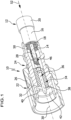
- FIG. 1 an advantageous embodiment of a coaxial connector according to the invention is shown schematically and is designated overall by the reference numeral 10.
- the Figures 1 and 2 show the coaxial connector 10 with a coaxial cable 12 connected thereto.
- the coaxial cable 12 has an inner cable conductor 14, an outer cable conductor 16 and a dielectric 18 arranged between the inner cable conductor 14 and the outer cable conductor 16.
- the coaxial cable 12 has a cable sheath 20 which surrounds the outer cable conductor 16 in the circumferential direction.
- the coaxial connector 10 has a two-part housing 22 made of metal, for example brass.
- the housing 22 is electrically conductive and forms an outer connector conductor 24 of the coaxial connector 10.
- the housing 22 has a first housing part 26, which is designed in the manner of a sleeve, and a second housing part 28, which is designed in the manner of a tube.
- the first housing part 26 is mounted on the second housing part 28 so as to be freely rotatable about a longitudinal axis 30 of the coaxial connector 10, wherein it surrounds a front section 32 of the second housing part 28 facing away from the coaxial cable 12 in the circumferential direction.
- the insulating part 34 is pressed into the second housing part 28.
- the insulating part 34 is made of an electrically non-conductive plastic material, for example Teflon.
- the insulating part 34 is penetrated by a connector inner conductor 36 which is pressed into the insulating part 34 and forms a contact pin 38 which protrudes from an end face 40 of the insulating part 34 facing away from the coaxial cable 12.
- the contact pin 38 dips into a front free space 42 of the second housing part 28 facing away from the coaxial cable 12 and can be contacted by a complementarily designed connector inner conductor of a mating connector.
- the connector inner conductor 36 is made of metal and is electrically conductive.
- the connector inner conductor 36 has a cable-side end face 44 into which a receiving space 46 aligned in the axial direction, i.e. coaxially to the longitudinal axis 30 of the coaxial connector 10, is inserted via an insertion bevel 48.
- a rear free space 50 of the second housing part 28 facing the coaxial cable 12 projects beyond the connector inner conductor 36 in the direction of the coaxial cable 12 and accommodates the previously exposed dielectric 18 and the exposed cable outer conductor 16 of the coaxial cable 12.
- the cable inner conductor 14 of the coaxial cable 12 can be inserted into the Figures 1 and 2 inserted into the receiving space 46 in the insertion direction illustrated by the arrow 52.
- the receiving space 46 forms a soldering area 54 which adjoins the insertion bevel 48 in the insertion direction 52 and to which a cylindrical guide section 58 adjoins in the insertion direction 52 via a conical constriction 56, which extends to a bottom 60 of the receiving space 46.
- the soldering area 54 of the receiving space 46 is formed by a cylindrical insertion section 62, a rounded transition section 64 adjoining the insertion section 62 in the insertion direction 52 and an extension section 66 adjoining the transition section 64 in the insertion direction 52, wherein the insertion section 62 adjoins the insertion bevel 48 of the receiving space 46 in the insertion direction 52.
- the transition from the insertion section 62 to the rounded transition section 64 is edge-free, as is the transition from the rounded transition section 64 to the extension section 66.
- the insertion section 62 is cylindrical, whereas the extension section 66 widens conically with increasing distance from the insertion section 62.
- solder receiving bores 68, 70 open into the soldering area 54 of the receiving space 46, each of which has an inner bore section 72 or 74, which is adjoined in the radial outward direction by an outer bore section 76, 78.
- the inner bore sections 72, 74 are cylindrical, and the outer bore sections 76, 78 each form an insertion chamfer 80 or 82 of the solder receiving bores 68, 70.
- the connector inner conductor 36 On its cable-side end face 44, the connector inner conductor 36 has two diametrically opposed recesses 84, 86 that extend in the radial direction from the insertion bevel 48 and the insertion section 62 to an outer surface 88 of the connector inner conductor 36.
- the recesses 84, 86 are arranged rotated by 90° relative to the solder receiving holes 68, 70 with respect to the longitudinal axis 30 of the coaxial connector 10. Air can be discharged to the outside via the recesses 84, 86 when the cable inner conductor 14 is inserted into the receiving space 46.
- the solder receiving bores 68, 70 open into the soldering region 54 in a region of the receiving space 46 that is downstream of the insertion section 62 with respect to the insertion direction 52.
- the mouth openings 90, 92 of the solder receiving bores 68, 70 extend into an end region of the rounded transition section 64 facing away from the cable and into a region of the extension section 66 that adjoins the transition section 64.
- the cable inner conductor 14 can be connected to the connector inner conductor 36 in a materially bonded and electrically conductive manner by producing a solder connection.
- Figures 8 to 12 show a first embodiment of a corresponding assembly method.
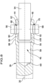
- a cylindrical punch 94 is introduced into the receiving space 46 via the insertion bevel 48.
- the penetration depth of the punch 94 into the receiving space 46 is selected such that the mouth openings 90, 92 of the solder receiving holes 68, 70 are covered by the punch 94.
- the diameter of the punch 94 is selected to be slightly larger than the maximum diameter of the cable inner conductor 14 to be connected. For example, it can be provided that the Diameter of the punch 94 is 0.01 mm to 0.02 mm larger than the maximum outer diameter of the cable inner conductor 14 to be connected.
- solder deposits are provided in the form of two solder wires 96, 98, which have a length that is adapted to the length of the solder receiving holes 68, 70, so that after deforming the solder wires 96, 98, as will be explained in more detail below, no material protrudes beyond the outer jacket surface 88 of the connector inner conductor 36.
- the cut solder wires 96, 98 are each inserted into a solder receiving bore 68, 70, with the stamp 94 forming a stop for the maximum penetration depth. After reaching the stamp 94, a defined deformation of the solder wires 96, 98 takes place by a deformation force F acting from the outside in the radial direction with the aid of a suitable deformation device.
- the deformation force F causes the solder wires 96, 98 to form a positive connection with the outer bore sections 76, 78 of the solder receiving bores 68, 70.
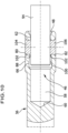
- solder wires 96, 98 being held in a positive connection in the solder receiving bores 68, 70, so that the solder wires 96, 98 each form a solder deposit 104 or 106, which is fixed in the solder receiving bore 68 or 70. This is shown by Figure 10 clearly.
- the stamp 94 is then removed from the receiving space 46.
- the exposed cable inner conductor 14 of the coaxial cable 12 can now be inserted into the receiving space 46 of the connector inner conductor 36, which is now provided with the solder deposits 104, 106. This is shown in Figure 11 illustrated.
- the inner cable conductor 14 extends in the axial direction through the soldering area 54 into the cylindrical guide section 58, which in combination with the cylindrical insertion section arranged at an axial distance from the guide section 58 ensures reliable guidance of the inner cable conductor 14 in the receiving space 46.
- the inner diameter of the cylindrical insertion section 62 is selected to be slightly larger than the maximum outer diameter of the cable inner conductor 14 to be connected, so that the cable inner conductor 14 introduced into the receiving space 46 is surrounded by a cylindrical annular gap 108 in the area of the insertion section 62, which is followed in the insertion direction 52 by a radially expanding annular gap 110 which surrounds the cable inner conductor 14 in the area of the transition section 64 and the extension section 66 in the circumferential direction. This is particularly evident from Figure 11 clearly.
- the two solder deposits 104, 106 are heated, for example by induction. Due to the capillary effect, a suction effect is created in the cylindrical annular gap 108, so that the solder liquefied by the heating first completely fills the cylindrical annular gap 108 with solder 112 and forms a meniscus-shaped end region 114, before excess solder 116 flows in the opposite direction of the widening annular gap 110 and solidifies there.
- a residual amount 118 of solder remains in the solder receiving holes 68, 70, which has a concave outer surface 120 in the solder receiving holes 68, 70. This is in Figure 12 illustrated.
- a high-frequency signal can be transmitted from the cable inner conductor 14 to the connector inner conductor.
- a defined signal path 122 is formed, whereby the signal path 122 starts from the cylindrical outer surface of the Cable inner conductor 14 first hits the meniscus-shaped end region 114 of the solder 112 and is guided from this end region over the cable-side end face 44 to the outer jacket surface 88 of the connector inner conductor 36 without penetrating into the receiving space 46 of the connector inner conductor 36.
- the amount of solder and the type of solder within the receiving space 46 have no influence on the course of the signal path 122.
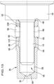
- FIG 13 An alternative procedure for mounting the cable inner conductor 14 on the connector inner conductor 36 is shown schematically, in which the positive connection of the solder deposits 104, 108 with the solder receiving holes 68, 70 is dispensed with.
- the stamp 94 which forms a stop for the cut-to-length solder wires 96, 98, is omitted; instead, the inner cable conductor 14 introduced into the receiving space 46 serves as a stop for the solder wires 96, 98, which are held in position by means of a suitable device.
- the liquefied solder flows, even with such a procedure, due to the capillary effect, into the cylindrical annular gap 108, which surrounds the inner cable conductor 14 in the circumferential direction in the region of the insertion section 62.
- the liquefied solder is sucked into the cylindrical annular gap 108 in order to completely fill it, forming a meniscus-shaped end section 114, before excess solder flows in the opposite direction into the widening annular gap 110, which surrounds the cable inner conductor 14 in the region of the transition section 64 and the extension section 66 in the circumferential direction.
- the length of the solder wires 96, 98 can be adapted to the wall thickness of the connector inner conductor 36. Alternatively, solder can also be melted from a long (endless) solder wire. Other geometric shapes can also be used for the solder deposits, for example spherical solder deposits or other free forms.
- the coaxial connector 10 is thus characterized by a short, defined and reproducible signal path 122 from the surface of the cable inner conductor 14 to the outer jacket surface 88 of the connector inner conductor 36, whereby disturbing passive intermodulations are avoided and the production of the solder connection requires only a minimal solder deposit volume.
Landscapes
- Coupling Device And Connection With Printed Circuit (AREA)
Description
- Die Erfindung betrifft einen Koaxialverbinder zum Anschließen an ein Koaxialkabel, mit einem Verbinderaußenleiter, der ein Isolierteil umgibt, das von einem Verbinderinnenleiter durchgriffen ist, wobei der Verbinderinnenleiter eine kabelseitige Stirnfläche aufweist, in die ein sich in axialer Richtung erstreckender Aufnahmeraum einmündet, wobei in den Aufnahmeraum ein Kabelinnenleiter des Koaxialkabels unter Ausbildung eines Ringspalts zwischen dem Kabelinnenleiter und der Wand des Aufnahmeraums in einer Einführrichtung einführbar ist, und wobei der Aufnahmeraum einen Lötbereich ausbildet, in den mindestens eine radiale Lotaufnahmebohrung einmündet.
- Derartige Koaxialverbinder können beispielsweise mit einem komplementär ausgestalteten Gegensteckverbinder lösbar verbunden werden, um eine elektrische Verbindung zwischen einem ersten Koaxialkabel und einem zweiten Koaxialkabel oder auch zwischen einem Koaxialkabel und einer elektrischen Baugruppe herzustellen. Koaxialverbinder dieser Art finden insbesondere in Basisstationen der Mobilfunktechnik Anwendung. Koaxialverbinder dieser Art können auch zum Anschließen eines Koaxialkabels an eine Leiterplatte verwendet werden. Außerdem können sie beispielsweise bei Koaxialkupplungen Verwendung finden.
- Die zum Anschluss an den Koaxialverbinder vorgesehenen Koaxialkabel weisen ein von einem Kabelinnenleiter durchgriffenes Dielektrikum auf, das in Umfangsrichtung von einem Kabelaußenleiter und einem isolierenden Kabelmantel umgeben ist.
- Zur Erfüllung stetig steigender Anforderungen an die Übertragungsqualität der in Rede stehenden Koaxialverbinder ist eine zuverlässige, prozesssichere Lötverbindung zwischen dem Kabelinnenleiter und dem Verbinderinnenleiter notwendig, die einen möglichst kurzen, definierten und reproduzierbaren Signalpfad für ein zu übertragendes Hochfrequenzsignal von der Oberfläche des Kabelinnenleiters zur äußeren Mantelfläche des Verbinderinnenleiters unter Vermeidung von Überlappungen ermöglicht. Von Bedeutung ist hierbei die Position und die Größe der Lötverbindung zwischen dem Verbinderinnenleiter und dem Kabelinnenleiter, die mit einer hohen Genauigkeit wiederholbar ausgebildet sein sollte. Zur Herstellung der Lötverbindung weisen die hier in Rede stehenden Koaxialverbinder mindestens eine radiale Lotaufnahmebohrung auf, die in einen Lötbereich eines sich in axialer Richtung erstreckenden Aufnahmeraums des Verbinderinnenleiters einmündet. In den Aufnahmeraum kann der Kabelinnenleiter unter Ausbildung eines Ringspalts zwischen dem Kabelinnenleiter und der Wand des Aufnahmeraums in einer Einführrichtung eingeführt werden, und die mindestens eine Lotaufnahmebohrung kann ein Lotdepot aufnehmen, das sich durch Erwärmen des Verbinderinnenleiters verflüssigt und in den Ringspalt zwischen dem Kabelinnenleiter und der Wand des Aufnahmeraums fließt zur Herstellung der Lötverbindung.
- Aus der
DE 10 2012 110 217 B4 ist ein Koaxialverbinder bekannt zum Anschließen an ein Koaxialkabel. Der Koaxialverbinder weist einen Verbinderaußenleiter auf, der ein Isolierteil umgibt, das von einem Verbinderinnenleiter durchgriffen ist. Der Verbinderinnenleiter weist einen sich in axialer Richtung erstreckenden Aufnahmeraum auf zur Aufnahme des Kabelinnenleiters. Der Kabelinnenleiter kann in einer Einführrichtung in den Aufnahmeraum eingeführt werden. In den Aufnahmeraum münden zwei einander diametral gegenüberliegende, sich in radialer Richtung erstreckende Lotaufnahmebohrungen, in denen jeweils ein Lotdepot angeordnet ist, das dazu dient, den in den Aufnahmeraum unter Ausbildung eines Ringspalts zwischen dem Kabelinnenleiter und der Wand des Aufnahmeraums eingeführten Kabelinnenleiter des Koaxialkabels mit der Wand des Aufnahmeraums mit Hilfe einer Lötverbindung stoffschlüssig und elektrisch leitend zu verbinden. Durch Erwärmen des Verbinderinnenleiters, beispielsweise mittels Induktion, kann das Lotdepot verflüssigt werden, so dass es aufgrund der Kapillarwirkung in den genannten Ringspalt fließt. In Abhängigkeit vorhandener Toleranzen des Aufnahmeraums und des Kabelinnenleiters variiert die Ausbreitung des durch die Kapillarwirkung verursachten Lotflusses. Dies führt zu variierenden Signalpfaden von der Oberfläche des Kabelinnenleiters zur äußeren Mantelfläche des Verbinderinnenleiters, wobei innerhalb des Signalpfades auch Überlappungen auftreten können, die die passive Intermodulation und damit die Übertragungsqualität negativ beeinflussen. Die undefinierte Ausbreitung des Lots erfordert außerdem eine entsprechend große Ausführung des Lotdepots, um eine sichere Lötverbindung in allen Toleranzlagen gewährleisten zu können. Insbesondere bei sehr kleinen Verbinderinnenleitern wird das Volumen des Lotdepots durch die Länge der sich in radialer Richtung erstreckenden Lotaufnahmebohrung und damit durch die vorhandene Wandstärke des Verbinderinnenleiters bestimmt. Eine Vergrößerung des Lotdepotvolumens führt zu einer Vergrößerung des Verbinderinnenleiters und damit des gesamten Koaxialverbinders. - Aus der
EP 1 724 877 B1 ist ein weiterer Koaxialverbinder bekannt zum Anschließen an ein Koaxialkabel. Auch dieser Koaxialverbinder weist einen Verbinderaußenleiter auf, der ein Isolierteil umgibt, das von einem Verbinderinnenleiter durchgriffen ist. Der Verbinderinnenleiter weist einen sich in radialer Richtung erstreckenden Aufnahmeraum in Form einer Durchgangsbohrung auf, in den der Kabelinnenleiter des Koaxialkabels unter Ausbildung eines Ringspalts zwischen dem Kabelinnenleiter und der Wand des Aufnahmeraums in einer Einführrichtung eingeführt werden kann. Auf ihrer dem anzuschließenden Koaxialkabel zugewandten Seite weist die Durchgangsbohrung einen sich stufig erweiternden Eingangsbereich auf zur formschlüssigen Aufnahme eines Lotdepots in Form eines Lotformteils. Auf ihrer dem anzuschließenden Koaxialkabel abgewandten Seite weist die Durchgangsbohrung einen Ausgangsbereich mit vergrößertem Durchmesser auf, der als Entlüftungskanal dient. Durch das Einführen des Kabelinnenleiters in die Durchgangsbohrung entsteht ein Ringspalt zwischen der Oberfläche des Kabelinnenleiters und der Wand der Durchgangsbohrung. Durch Erwärmen des Verbinderinnenleiters, beispielsweise mittels Induktion, kann das im Eingangsbereich der Durchgangsbohrung angeordnete Lotdepot verflüssigt werden, so dass das Lot auf die das Lotdepot durchgreifende Oberfläche des Kabelinnenleiters und aufgrund der Kapillarwirkung in den vorgenannten Ringspalt fließen kann, um nach dem Erstarren eine stoffschlüssige Verbindung zwischen dem Verbinderinnenleiter und dem Kabelinnenleiter auszubilden. Nachteilig wirkt sich die durch den konstruktiven Aufbau bedingte beachtliche Baugröße des Verbinderinnenleiters im Eingangsbereich der Durchgangsbohrung aus, da das Lotdepot in Umfangsrichtung von einer Wand der Durchgangsbohrung umgeben ist. In Abhängigkeit vorhandener Toleranzen variiert die Ausbreitung des durch die Kapillarwirkung verursachten Lotflusses. Dies führt auch bei einer derartigen Ausgestaltung zu variierenden Signalpfaden von der Oberfläche des Kabelinnenleiters zur äußeren Mantelfläche des Verbinderinnenleiters und wirkt sich negativ auf die Übertragungsqualität des Koaxialverbinders aus. Aus derDE102013100438 B3 ist ein Koaxialverbinder nach dem Oberbegriff des Anspruchs 1 bekannt. - Aufgabe der Erfindung ist es daher, einen gattungsgemäßen Koaxialverbinder derart weiterzuentwickeln, dass eine zuverlässige, prozesssichere Lötverbindung zwischen dem Kabelinnenleiter und dem Verbinderinnenleiter ausgebildet werden kann, die einen kurzen, definierten und reproduzierbaren Signalpfad von der Oberfläche des Kabelinnenleiters zur äußeren Mantelfläche des Verbinderinnenleiters unter Vermeidung störender passiver Intermodulation bei Bereitstellung eines minimalen Lotdepotvolumens ermöglicht.
- Diese Aufgabe wird bei einem gattungsgemäßen Koaxialverbinder erfindungsgemäß dadurch gelöst, dass der Lötbereich einen Erweiterungsabschnitt aufweist, der sich mit zunehmendem Abstand zur kabelseitigen Stirnfläche des Verbinderinnenleiters in radialer Richtung erweitert.
- Wie bereits erwähnt, bildet sich beim Einführen des Kabelinnenleiters in den Aufnahmeraum zwischen dem Kabelinnenleiter und der Wand des Aufnahmeraums ein Ringspalt aus, in den das sich beim Erwärmen des Verbinderinnenleiters verflüssigende Lot fließen kann. Die Bereitstellung des sich mit zunehmendem Abstand zur kabelseitigen Stirnfläche des Verbinderinnenleiters in radialer Richtung erweiternden Erweiterungsabschnitts hat zur Folge, dass sich die Spaltbreite des Ringspalts im Bereich des Erweiterungsabschnitts vergrößert, das heißt dass sich die radiale Ausdehnung des Ringspalts vergrößert. Die Spaltbreite kann beispielsweise 0,05 mm bis 0,5 mm betragen.
- Durch die Bereitstellung des sich in radialer Richtung erweiternden Erweiterungsabschnitts des Lötbereichs entsteht im Erweiterungsabschnitt ein sich entgegen der Einführrichtung des Kabelinnenleiters verjüngender Ringspalt. Die Kapillarwirkung dieser Ringspaltgeometrie bewirkt bei der Erwärmung des Verbinderinnenleiters und des in die mindestens eine radiale Lotaufnahmebohrung eingebrachten Lotdepots eine gerichtete und definierte Ausbreitung des verflüssigten Lots in den sich verjüngenden Ringspalt hinein. Es hat sich gezeigt, dass das verflüssigte Lot aufgrund der einwirkenden Kapillarkräfte einer Sogwirkung in die der Einführrichtung des Kabelinnenleiters entgegengesetzte Richtung unterliegt und zuerst den Bereich des Ringspalts mit minimaler Spaltbreite zwischen dem Kabelinnenleiter und der Wand des Aufnahmeraums ausfüllt und erst anschließend überschüssiges Lot in den sich in Einführrichtung des Kabelinnenleiters an die Lotaufnahmebohrung anschließenden Bereich des Ringspalts innerhalb des Erweiterungsabschnitts fließt. Somit wird beim Erwärmen des Kabelinnenleiters zunächst der Bereich des Ringspalts mit minimaler Spaltbreite mit Lot gefüllt. Dies ermöglicht eine genaue und minimierte Dimensionierung des Lotdepots und der mindestens einen Lotaufnahmebohrung zur Aufnahme des Lotdepots sowie eine damit einhergehende minimierte Wandstärke des Kabelinnenleiters. In Abhängigkeit vorhandener Toleranzen des Aufnahmeraums und des Kabelinnenleiters entstehen unterschiedliche Mengen an überschüssigem Lot, das nach dem Befüllen des Bereichs des Ringspalts mit minimaler Spaltbreite in den bezogen auf die Einführrichtung des Kabelinnenleiters der Lotaufnahmebohrung nachfolgenden Bereich des Ringspalts abfließt. Dieses überschüssige Lot hat übertragungstechnisch keine Bedeutung, da es vom Signalpfad des Hochfrequenzsignals nicht erfasst wird. Dies führt zu einem stets gleichen Signalpfad, der sich von der Oberfläche des Kabelinnenleiters zur äußeren Mantelfläche des Verbinderinnenleiters erstreckt. Minimale Überlappungen innerhalb des Signalpfades sind lediglich bei Ausbildung eines Meniskus an dem dem anzuschließenden Koaxialkabel zugewandten Endbereich des erstarrten Lots möglich.
- Die erfindungsgemäße Ausgestaltung des Koaxialverbinders ermöglicht folglich eine zuverlässige, prozesssichere Lötverbindung zwischen dem Kabelinnenleiter und dem Verbinderinnenleiter, wobei die Verbindung einen kurzen, definierten und reproduzierbaren Signalpfad von der Oberfläche des Kabelinnenleiters zur äußeren Mantelfläche des Verbinderinnenleiters gewährleistet unter Vermeidung einer störenden passiven Intermodulation und bei Bereitstellung eines minimalen Lotdepotvolumens.
- Von Vorteil ist es, wenn sich der Erweiterungsabschnitt mit zunehmendem Abstand zum Einführabschnitt kegelförmig erweitert.
- Zur Führung des Kabelinnenleiters weist der Lötbereich bei einer vorteilhaften Ausführungsform des erfindungsgemäßen Koaxialverbinders im Bereich zwischen der kabelseitigen Stirnfläche des Verbinderinnenleiters und dem Erweiterungsabschnitt einen zylindrischen Einführabschnitt auf. Beim Einführen des Kabelinnenleiters in den Aufnahmeraum bildet sich im Bereich des zylindrischen Einführabschnitts zwischen dem Kabelinnenleiter und der Wand des Aufnahmeraums ein zylindrischer Ringspalt aus, in den der sich entgegen der Einführrichtung des Kabelinnenleiters verjüngende Ringspalt einmündet und in den das sich beim Erwärmen des Verbinderinnenleiters verflüssigende Lot aufgrund der auf das Lot einwirkenden Kapillarkräfte fließen kann. Das verflüssigte Lot füllt daher zuerst den im Einführabschnitt des Lötbereichs angeordneten zylindrischen Ringspalt zwischen dem Kabelinnenleiter und der Wand des Aufnahmeraums, bevor überschüssiges Lot in den sich in Einführrichtung an die Lotaufnahmebohrung anschließenden Bereich des sich erweiternden Ringspalts fließt.
- Bevorzugt ist die Spaltbreite des zylindrischen Ringspalts maximal so groß wie die minimale Spaltbreite des sich entgegen der Einführrichtung des Kabelinnenleiters verjüngenden Ringspalts.
- Die Länge des zylindrischen Einführabschnitts beträgt bevorzugt mindestens 0,05 mm, insbesondere mindestens 0,2 mm. Dies erlaubt eine platzsparende kurze Ausgestaltung des Verbinderinnenleiters unter Gewährleistung einer funktionssicheren Führung des Kabelinnenleiters.
- Zur Verbesserung der Kapillarwirkung und zur Vermeidung von Gratbildung beim Einführen des Kabelinnenleiters in den Aufnahmeraum des Verbinderinnenleiters ist es von Vorteil, wenn der zylindrische Einführabschnitt über einen abgerundeten Übergangsabschnitt in den Erweiterungsabschnitt übergeht.
- Besonders günstig ist es, wenn der Einführabschnitt kantenfrei in den Übergangsabschnitt übergeht und/oder der Übergangsabschnitt kantenfrei in den Erweiterungsabschnitt übergeht.
- Die mindestens eine Lotaufnahmebohrung mündet bei einer vorteilhaften Ausgestaltung der Erfindung bezogen auf die Einführrichtung des Kabelinnenleiters in einen dem Einführabschnitt nachfolgenden Bereich des Aufnahmeraums in den Lötbereich ein. Die mindestens eine Lotaufnahmebohrung mündet also bezogen auf die Einführrichtung des Kabelinnenleiters hinter dem zylindrischen Einführabschnitt in den Lötbereich und das Lot wird beim Erwärmen des Verbinderinnenleiters aufgrund der auf das Lot einwirkenden Kapillarkräfte zuverlässig in den zylindrischen Ringspalt eingesaugt, der den Kabelinnenleiter im Einführabschnitt in Umfangsrichtung umgibt.
- Zur Aufrechterhaltung einer hohen mechanischen Stabilität des Verbinderinnenleiters ist es von Vorteil, wenn der Durchmesser der mindestens einen Lotaufnahmebohrung kleiner ist als der Durchmesser des Einführabschnitts.
- Günstig ist es, wenn die mindestens eine Lotaufnahmebohrung einen radial innenliegenden Bohrungsabschnitt und einen radial außenliegenden Bohrungsabschnitt aufweist, wobei sich die Lotaufnahmebohrung im außenliegenden Bohrungsabschnitt in radialer Richtung erweitert. Der radial außenliegende Bohrungsabschnitt mit sich vergrößerndem Durchmesser erlaubt es, das Lotdepot nach dem Einbringen in die Lotaufnahmebohrung durch Beaufschlagung mit einer radial wirkenden Umformkraft so umzuformen, dass es formschlüssig fixiert werden kann.
- Günstigerweise bildet der radial außenliegende Bohrungsabschnitt der mindestens einen Lotaufnahmebohrung eine Einführfase aus.
- Der radial innenliegende Bohrungsabschnitt ist günstigerweise zylindrisch ausgestaltet.
- Bei einer bevorzugten Ausführungsform der Erfindung münden in den Lötbereich des Aufnahmeraums mehrere in Umfangsrichtung des Aufnahmeraums versetzt zueinander angeordnete radiale Lotaufnahmebohrungen. Beispielsweise können zwei einander diametral gegenüberliegende Lotaufnahmebohrungen in den Lötbereich einmünden.
- Besonders vorteilhaft ist es, wenn in der mindestens einen Lotaufnahmebohrung ein Lotdepot formschlüssig gehalten ist. Wie bereits erwähnt, kann das in die mindestens eine Lotaufnahmebohrung eingebrachte Lotdepot beispielsweise durch Beaufschlagung mit einer radialen Umformkraft derart umgeformt werden, dass es mit der Lotaufnahmebohrung einen Formschluss ausbildet.
- Der Aufnahmeraum weist bei einer bevorzugten Ausgestaltung der Erfindung eine Einführfase auf, über die der Aufnahmeraum in die kabelseitige Stirnfläche des Verbinderinnenleiters einmündet. Die Einführfase des Aufnahmeraums begünstigt in vorteilhafter Weise die Ausbildung eines definierten Abschlusses des erstarrten Lots in Form eines Meniskus. Außerdem erleichtert sie das Einführen des anzuschließenden Kabelinnenleiters in den Aufnahmeraum des Verbinderinnenleiters.
- Um die axiale Ausrichtung des Kabelinnenleiters innerhalb des Verbinderinnenleiters zu vereinfachen, weist der Aufnahmeraum bei einer vorteilhaften Ausgestaltung der Erfindung einen zylindrischen Führungsabschnitt zur Führung des Kabelinnenleiters auf, der bezogen auf die Einführrichtung des Kabelinnenleiters dem Erweiterungsabschnitt nachgeordnet ist, also hinter dem Erweiterungsabschnitt angeordnet ist, wobei der Durchmesser des Führungsabschnitts kleiner ist als der größte Durchmesser des Erweiterungsabschnitts. Der zylindrische Führungsabschnitt stellt insbesondere in Kombination mit dem axial beabstandeten zylindrischen Einführabschnitt eine zuverlässige Führung des Kabelinnenleiters im Aufnahmeraum sicher.
- Der Übergang vom Erweiterungsabschnitt zum Führungsabschnitt erfolgt bei einer bevorzugten Ausgestaltung der Erfindung über eine konische Verengung.
- Günstigerweise ist der Durchmesser des Führungsabschnitts so groß wie der Durchmesser des Einführabschnitts.
- Die nachfolgende Beschreibung einer vorteilhaften Ausführungsform der Erfindung dient im Zusammenhang mit der Zeichnung der näheren Erläuterung. Es zeigen:
- Figur 1:
- eine aufgebrochene perspektivische Darstellung eines Koaxialverbinders, der an ein Koaxialkabel angeschlossen ist;
- Figur 2:
- eine Längsschnittansicht des Koaxialverbinders mit angeschlossenem Koaxialkabel aus
Figur 1 ; - Figur 3:
- eine teilweise aufgebrochene Seitenansicht eines Verbinderinnenleiters des Koaxialverbinders aus
Figur 1 ; - Figur 4:
- eine vergrößerte Darstellung von Detail Y aus
Figur 3 ; - Figur 5:
- eine Schnittansicht des Verbinderinnenleiters entlang der Linie 5-5 aus
Figur 4 ; - Figur 6:
- eine perspektivische Darstellung des Verbinderinnenleiters mit ange-schlossenem Koaxialkabel;
- Figur 7:
- eine vergrößerte Darstellung von Detail Z aus
Figur 6 ; - Figur 8:
- eine teilweise aufgebrochene Teildarstellung des Verbinderinnenlei-ters in einem ersten Montageschnitt, in dem Lotdepots bereitgestellt werden;
- Figur 9:
- eine teilweise aufgebrochene Teildarstellung des Verbinderinnenlei-ters in einem zweiten Montageschritt mit in Lotaufnahmebohrungen eingeführten Lotdepots;
- Figur 10:
- eine teilweise aufgebrochene Teildarstellung des Verbinderinnenlei-ters in einem dritten Montageschritt mit in den Lotaufnahmebohrun-gen fixierten Lotdepots;
- Figur 11:
- eine teilweise aufgebrochene Teildarstellung des Verbinderinnenlei-ters in einem vierten Montageschnitt mit in einen Aufnahmeraum eingeführtem Kabelinnenleiter;
- Figur 12:
- eine Teilschnittansicht des Verbinderinnenleiters nach dem Verlöten des eingeführten Kabelinnenleiters;
- Figur 13:
- eine teilweise aufgebrochene Darstellung des Verbinderinnenleiters bei einer alternativen Montage des Kabelinnenleiters.
- In der Zeichnung ist eine vorteilhafte Ausführungsform eines erfindungsgemäßen Koaxialverbinders schematisch dargestellt und insgesamt mit dem Bezugszeichen 10 belegt. Die
Figuren 1 und2 zeigen den Koaxialverbinder 10 mit einem daran angeschlossenen Koaxialkabel 12. Das Koaxialkabel 12 weist einen Kabelinnenleiter 14, einen Kabelaußenleiter 16 und ein zwischen dem Kabelinnenleiter 14 und dem Kabelaußenleiter 16 angeordnetes Dielektrikum 18 auf. Außerdem weist das Koaxialkabel 12 einen Kabelmantel 20 auf, der den Kabelaußenleiter 16 in Umfangsrichtung umgibt. - Der Koaxialverbinder 10 weist ein zweiteiliges Gehäuse 22 auf, das aus Metall, beispielsweise aus Messing, gefertigt ist. Das Gehäuse 22 ist elektrisch leitfähig und bildet einen Verbinderaußenleiter 24 des Koaxialverbinders 10 aus.
- Das Gehäuse 22 weist ein erstes Gehäuseteil 26 auf, das nach Art einer Hülse ausgebildet ist, und ein zweites Gehäuseteil 28, das nach Art eines Rohres ausgestaltet ist. Das erste Gehäuseteil 26 ist um eine Längsachse 30 des Koaxialverbinders 10 frei drehbar am zweiten Gehäuseteil 28 gelagert, wobei es einen dem Koaxialkabel 12 abgewandten vorderen Abschnitt 32 des zweiten Gehäuseteils 28 in Umfangsrichtung umgibt.
- In das zweite Gehäuseteil 28 ist ein Isolierteil 34 eingepresst. Das Isolierteil 34 ist aus einem elektrisch nicht leitfähigen Kunststoffmaterial gefertigt, beispielsweise aus Teflon.
- Das Isolierteil 34 wird von einem Verbinderinnenleiter 36 durchgriffen, der in das Isolierteil 34 eingepresst ist und einen Kontaktstift 38 ausbildet, der aus einer dem Koaxialkabel 12 abgewandten Stirnfläche 40 des Isolierteils 34 herausragt. Der Kontaktstift 38 taucht in einen dem Koaxialkabel 12 abgewandten vorderen Freiraum 42 des zweiten Gehäuseteils 28 hinein und kann von einem komplementär ausgestalteten Verbinderinnenleiter eines Gegensteckverbinders kontaktiert werden. Der Verbinderinnenleiter 36 ist aus Metall gefertigt und elektrisch leitfähig.
- Der Verbinderinnenleiter 36 weist eine kabelseitige Stirnfläche 44 auf, in die ein sich in axialer Richtung, das heißt koaxial zur Längsachse 30 des Koaxialverbinders 10 ausgerichteter Aufnahmeraum 46 über eine Einführfase 48 einmündet. Ein dem Koaxialkabel 12 zugewandter hinterer Freiraum 50 des zweiten Gehäuseteils 28 überragt den Verbinderinnenleiter 36 in Richtung auf das Koaxialkabel 12 und nimmt das zuvor freigelegte Dielektrikum 18 und den freigelegten Kabelaußenleiter 16 des Koaxialkabels 12 auf. Hierbei kann der Kabelinnenleiter 14 des Koaxialkabels 12 in einer in den
Figuren 1 und2 durch den Pfeil 52 veranschaulichten Einführrichtung in den Aufnahmeraum 46 eingeführt werden. - Wie insbesondere aus den
Figuren 4 und5 deutlich wird, bildet der Aufnahmeraum 46 einen sich in Einführrichtung 52 an die Einführfase 48 anschließenden Lötbereich 54 aus, an den sich in Einführrichtung 52 über eine konische Verengung 56 ein zylindrischer Führungsabschnitt 58 anschließt, der sich bis zu einem Boden 60 des Aufnahmeraums 46 erstreckt. - Der Lötbereich 54 des Aufnahmeraums 46 wird bei der dargestellten Ausführungsform von einem zylindrischen Einführabschnitt 62, einem sich in Einführrichtung 52 an den Einführabschnitt 62 anschließenden abgerundeten Übergangsabschnitt 64 und einem sich in Einführrichtung 52 an den Übergangsabschnitt 64 anschließenden Erweiterungsabschnitt 66 gebildet, wobei sich der Einführabschnitt 62 in Einführrichtung 52 an die Einführfase 48 des Aufnahmeraums 46 anschließt. Der Übergang vom Einführabschnitt 62 zum abgerundeten Übergangsabschnitt 64 erfolgt ebenso wie der Übergang vom abgerundeten Übergangsabschnitt 64 zum Erweiterungsabschnitt 66 kantenfrei.
- Der Einführabschnitt 62 ist zylindrisch ausgestaltet, wohingegen sich der Erweiterungsabschnitt 66 mit zunehmendem Abstand vom Einführabschnitt 62 kegelförmig erweitert.
- In den Lötbereich 54 des Aufnahmeraums 46 münden zwei einander diametral gegenüberliegende Lotaufnahmebohrungen 68, 70, die jeweils einen innenliegenden Bohrungsabschnitt 72 bzw. 74 aufweisen, an den sich in radialer Richtung nach außen ein außenliegender Bohrungsabschnitt 76, 78 anschließt. Die innenliegenden Bohrungsabschnitte 72, 74 sind zylindrisch ausgestaltet, und die außenliegenden Bohrungsabschnitte 76, 78 bilden jeweils eine Einführfase 80 bzw. 82 der Lotaufnahmebohrungen 68, 70 aus.
- An seiner kabelseitigen Stirnfläche 44 weist der Verbinderinnenleiter 36 zwei einander diametral gegenüberliegende Vertiefungen 84, 86 auf, die sich in radialer Richtung von der Einführfase 48 und dem Einführabschnitt 62 bis zu einer äußeren Mantelfläche 88 des Verbinderinnenleiters 36 erstrecken. Die Vertiefungen 84, 86 sind bezogen auf die Längsachse 30 des Koaxialverbinders 10 um 90° zu den Lotaufnahmebohrungen 68, 70 verdreht angeordnet. Über die Vertiefungen 84, 86 kann beim Einführen des Kabelinnenleiters 14 in den Aufnahmeraum 46 Luft nach außen abgeführt werden.
- Die Lotaufnahmebohrungen 68, 70 münden in einem dem Einführabschnitt 62 bezogen auf die Einführrichtung 52 nachgeordneten Bereich des Aufnahmeraums 46 in den Lötbereich 54. In der dargestellten Ausführungsform erstrecken sich die Mündungsöffnungen 90, 92 der Lotaufnahmebohrungen 68, 70 in einem kabelabgewandten Endbereich des abgerundeten Übergangsabschnitts 64 und einem sich an den Übergangsabschnitt 64 anschließenden Bereich des Erweiterungsabschnitts 66.
- Der Kabelinnenleiter 14 kann mit dem Verbinderinnenleiter 36 stoffschlüssig und elektrisch leitend verbunden werden, indem eine Lötverbindung hergestellt wird. Die
Figuren 8 bis 12 zeigen eine erste Ausführungsform eines entsprechenden Montageverfahrens. - In einem ersten Montageschritt, der in
Figur 8 veranschaulicht ist, wird ein zylindrischer Stempel 94 über die Einführfase 48 in den Aufnahmeraum 46 eingeführt. Die Eindringtiefe des Stempels 94 in den Aufnahmeraum 46 wird so gewählt, dass die Mündungsöffnungen 90, 92 der Lotaufnahmebohrungen 68, 70 vom Stempel 94 abgedeckt werden. Der Durchmesser des Stempels 94 ist geringfügig größer gewählt als der maximale Durchmesser des anzuschließenden Kabelinnenleiters 14. Beispielsweise kann vorgesehen sein, dass der Durchmesser des Stempels 94 um 0,01 mm bis 0,02 mm größer ist als der maximale Außendurchmesser des anzuschließenden Kabelinnenleiters 14. - Nach Einführen des Stempels 94 in den Aufnahmeraum 46 werden Lotdepots in Form von zwei Lotdrähten 96, 98 bereitgestellt, die eine Länge aufweisen, die an die Länge der Lotaufnahmebohrungen 68, 70 angepasst ist, so dass nach dem Verformen der Lotdrähte 96, 98, wie es nachfolgend näher erläutert wird, kein Material über die äußere Mantelfläche 88 des Verbinderinnenleiters 36 herausragt.
- Die abgelängten Lotdrähte 96, 98 werden jeweils in eine Lotaufnahmebohrung 68, 70 eingeführt, wobei der Stempel 94 einen Anschlag für die maximale Eindringtiefe ausbildet. Nach Erreichen des Stempels 94 erfolgt eine definierte Verformung der Lotdrähte 96, 98 durch eine von außen in radialer Richtung einwirkende Verformungskraft F mit Hilfe einer geeigneten Verformungseinrichtung.
- Aufgrund der Beaufschlagung der abgelängten Lotdrähte 96, 98 mit der radial ausgerichteten Verformungskraft F fließt ein Teil 102 des weichen, verformbaren Lots in einen den Stempel 94 im Bereich des Erweiterungsabschnitts 66 in Umfangsrichtung umgebenden ringförmigen Hohlraum 100 und bildet einen Formschluss aus. In entsprechender Weise bewirkt die Verformungskraft F eine formschlüssige Anlage der Lotdrähte 96, 98 an den außenliegenden Bohrungsabschnitten 76, 78 der Lotaufnahmebohrungen 68, 70. Dies hat zur Folge, dass die Lotdrähte 96, 98 in den Lotaufnahmebohrungen 68, 70 formschlüssig gehalten sind, so dass die Lotdrähte 96, 98 jeweils ein Lotdepot 104 bzw. 106 ausbilden, das in der Lotaufnahmebohrung 68 bzw. 70 festgelegt ist. Dies wird aus
Figur 10 deutlich. Anschließend wird der Stempel 94 aus dem Aufnahmeraum 46 entfernt. - In den Aufnahmeraum 46 des nunmehr mit den Lotdepots 104, 106 versehenen Verbinderinnenleiters 36 kann nun der freigelegte Kabelinnenleiter 14 des Koaxialkabels 12 eingeführt werden. Dies ist in
Figur 11 veranschaulicht. Der Kabelinnenleiter 14 erstreckt sich in axialer Richtung durch den Lötbereich 54 hindurch bis in den zylindrischen Führungsabschnitt 58, der in Kombination mit dem in axialem Abstand zum Führungsabschnitt 58 angeordneten zylindrischen Einführabschnitt eine zuverlässige Führung des Kabelinnenleiters 14 im Aufnahmeraum 46 sicherstellt. - Der Innendurchmesser des zylindrischen Einführabschnitts 62 ist geringfügig größer gewählt als der maximale Außendurchmesser des anzuschließenden Kabelinnenleiters 14, so dass der in den Aufnahmeraum 46 eingeführte Kabelinnenleiter 14 im Bereich des Einführabschnitts 62 von einem zylindrischen Ringspalt 108 umgeben ist, an den sich in Einführrichtung 52 ein sich radial erweiternder Ringspalt 110 anschließt, der den Kabelinnenleiter 14 im Bereich des Übergangsabschnitts 64 und des Erweiterungsabschnitts 66 in Umfangsrichtung umgibt. Dies wird insbesondere aus
Figur 11 deutlich. - Zur Herstellung einer Lötverbindung zwischen dem Kabelinnenleiter 14 und dem Verbinderinnenleiter 36 erfolgt eine Erwärmung, beispielsweise durch Induktion, der beiden Lotdepots 104, 106. Bedingt durch die Kapillarwirkung entsteht eine Sogwirkung in den zylindrischen Ringspalt 108 hinein, so dass das durch die Erwärmung verflüssigte Lot zuerst den zylindrischen Ringspalt 108 vollständig mit Lot 112 ausfüllt und einen meniskusförmigen Endbereich 114 ausbildet, bevor überschüssiges Lot 116 in die entgegengesetzte Richtung des sich erweiternden Ringspalts 110 fließt und dort erstarrt. In Abhängigkeit von der Größe der Lotdepots 104, 106 verbleibt in den Lotaufnahmebohrungen 68, 70 eine Restmenge 118 von Lot, das in den Lotaufnahmebohrungen 68, 70 eine konkave Außenfläche 120 aufweist. Dies ist in
Figur 12 veranschaulicht. - Nach erfolgtem Anschließen des Koaxialkabels 12 an den Koaxialverbinder 10 und dem Herstellen einer Lötverbindung zwischen dem Kabelinnenleiter 14 und dem Verbinderinnenleiter 36 kann vom Kabelinnenleiter 14 ein Hochfrequenzsignal auf den Verbinderinnenleiter übertragen werden. Bei der Übertragung des Hochfrequenzsignals bildet sich ein definierter Signalpfad 122 aus, wobei der Signalpfad 122 ausgehend von der zylindrischen Außenfläche des Kabelinnenleiters 14 zunächst auf den meniskusförmigen Endbereich 114 des Lots 112 trifft und von diesem Endbereich über die kabelseitige Stirnfläche 44 zur äußeren Mantelfläche 88 des Verbinderinnenleiters 36 geleitet wird, ohne in den Aufnahmeraum 46 des Verbinderinnenleiters 36 einzudringen. Lotmenge und Lotausführung innerhalb des Aufnahmeraums 46 haben keinen Einfluss auf den Verlauf des Signalpfads 122.
- In
Figur 13 ist eine alternative Vorgehensweise zur Montage des Kabelinnenleiters 14 am Verbinderinnenleiter 36 schematisch dargestellt, bei der auf die formschlüssige Verbindung der Lotdepots 104, 108 mit den Lotaufnahmebohrungen 68, 70 verzichtet wird. Bei der inFigur 13 veranschaulichten Vorgehensweise entfällt der Stempel 94, der einen Anschlag für die abgelängten Lotdrähte 96, 98 bildet, vielmehr dient der in den Aufnahmeraum 46 eingeführte Kabelinnenleiter 14 als Anschlag für die Lotdrähte 96, 98, die mittels einer geeigneten Vorrichtung in ihrer Position gehalten werden. Durch Erwärmung der Lotdrähte 96, 98 fließt das verflüssigte Lot auch bei einer derartigen Vorgehensweise bedingt durch die Kapillarwirkung in den zylindrischen Ringspalt 108, der den Kabelinnenleiter 14 im Bereich des Einführabschnitts 62 in Umfangsrichtung umgibt. Das verflüssigte Lot wird in den zylindrischen Ringspalt 108 hineingesaugt, um diesen unter Ausbildung eines meniskusförmigen Endabschnitts 114 vollständig auszufüllen, bevor überschüssiges Lot in die entgegengesetzte Richtung in den sich erweiternden Ringspalt 110 fließt, der den Kabelinnenleiter 14 im Bereich des Übergangsabschnitts 64 und des Erweiterungsabschnitts 66 in Umfangsrichtung umgibt. Die Länge der Lotdrähte 96, 98 kann an die Wandstärke des Verbinderinnenleiters 36 angepasst werden. Alternativ kann auch das Abschmelzen von Lot von einem langen (endlosen) Lotdraht erfolgen. Es können auch andere geometrische Formen für die Lotdepots zum Einsatz kommen, beispielsweise kugelförmige Lotdepots oder auch andere Freiformen. - Der Koaxialverbinder 10 zeichnet sich somit durch einen kurzen, definierten und reproduzierbaren Signalpfad 122 von der Oberfläche des Kabelinnenleiters 14 zur äußeren Mantelfläche 88 des Verbinderinnenleiters 36 aus, wobei störende passive Intermodulationen vermieden werden und die Herstellung der Lötverbindung lediglich ein minimales Lotdepotvolumen erfordert.
Claims (15)
- Koaxialverbinder zum Anschließen an ein Koaxialkabel (12), mit einem Verbinderaußenleiter (24), der ein Isolierteil (34) umgibt, das von einem Verbinderinnenleiter (36) durchgriffen ist, wobei der Verbinderinnenleiter (36) eine kabelseitige Stirnfläche (44) aufweist, in die ein sich in axialer Richtung erstreckender Aufnahmeraum (46) einmündet, wobei in den Aufnahmeraum (46) ein Kabelinnenleiter (14) des Koaxialkabels (12) unter Ausbildung eines Ringspalts (108, 110) zwischen dem Kabelinnenleiter (14) und der Wand des Aufnahmeraums (46) in einer Einführrichtung (52) einführbar ist, und wobei der Aufnahmeraum (46) einen Lötbereich (54) ausbildet, in den mindestens eine radiale Lotaufnahmebohrung (68, 70) einmündet, dadurch gekennzeichnet, dass der Lötbereich (54) einen Erweiterungsabschnitt (66) aufweist, der sich mit zunehmendem Abstand zur kabelseitigen Stirnfläche (44) in radialer Richtung erweitert.
- Koaxialverbinder nach Anspruch 1, dadurch gekennzeichnet, dass sich der Erweiterungsabschnitt (66) mit zunehmendem Abstand zum Einführabschnitt (62) kegelförmig erweitert.
- Koaxialverbinder nach Anspruch 1 oder 2, dadurch gekennzeichnet, dass der Lötbereich (54) im Bereich zwischen der kabelseitigen Stirnfläche (44) des Verbinderinnenleiters (36) und dem Erweiterungsabschnitt (66) einen zylindrischen Einführabschnitt (62) aufweist zur Führung des Kabelinnenleiters (14).
- Koaxialverbinder nach Anspruch 3, dadurch gekennzeichnet, dass der Einführabschnitt (62) über einen abgerundeten Übergangsabschnitt (64) in den Erweiterungsabschnitt (66) übergeht.
- Koaxialverbinder nach Anspruch 3 oder 4, dadurch gekennzeichnet, dass der Einführabschnitt (62) kantenfrei in den Übergangsabschnitt (64) übergeht und/oder dass der Übergangsabschnitt (64) kantenfrei in den Erweiterungsabschnitt (66) übergeht.
- Koaxialverbinder nach Anspruch 3, 4 oder 5, dadurch gekennzeichnet, dass die mindestens eine Lotaufnahmebohrung (68, 70) bezogen auf die Einführrichtung (52) des Kabelinnenleiters (14) in einem dem Einführabschnitt (62) nachfolgenden Bereich des Aufnahmeraums (46) in den Lötbereich (54) einmündet.
- Koaxialverbinder nach Anspruch 3, 4, 5 oder 6, dadurch gekennzeichnet, dass der Durchmesser der mindestens einen Lotaufnahmebohrung (68, 70) kleiner ist als der Durchmesser des Einführabschnitts (62).
- Koaxialverbinder nach einem der voranstehenden Ansprüche, dadurch gekennzeichnet, dass die mindestens eine Lotaufnahmebohrung (68, 70) einen radial innenliegenden Bohrungsabschnitt (72, 74) und einen radial außenliegenden Bohrungsabschnitt (76, 78) aufweist, wobei sich die Lotaufnahmebohrung (68, 70) im radial außenliegenden Bohrungsabschnitt (76, 78) in radialer Richtung erweitert.
- Koaxialverbinder nach Anspruch 8, dadurch gekennzeichnet, dass der radial außenliegende Bohrungsabschnitt (76, 78) eine Einführfase (80, 82) ausbildet.
- Koaxialverbinder nach einem der voranstehenden Ansprüche, dadurch gekennzeichnet, dass in den Lötbereich (54) des Aufnahmeraums (46) mehrere in Umfangsrichtung des Aufnahmeraums (46) versetzt zueinander angeordnete radiale Lotaufnahmebohrungen (68, 70) einmünden.
- Koaxialverbinder nach einem der voranstehenden Ansprüche, dadurch gekennzeichnet, dass in der mindestens einen Lotaufnahmebohrung (68, 70) ein Lotdepot (104, 106) formschlüssig gehalten ist.
- Koaxialverbinder nach einem der voranstehenden Ansprüche, dadurch gekennzeichnet, dass der der Aufnahmeraum (46) eine Einführfase (48) aufweist, über die der Aufnahmeraum (46) in die kabelseitige Stirnfläche (44) des Verbinderinnenleiters (36) einmündet.
- Koaxialverbinder nach einem der voranstehenden Ansprüche, dadurch gekennzeichnet, dass der Aufnahmeraum (46) einen zylindrischen Führungsabschnitt (58) zur Führung des Kabelinnenleiters (14) aufweist, der bezogen auf die Einführrichtung (52) des Kabelinnenleiters (14) dem Erweiterungsabschnitt (66) nachgeordnet ist, wobei der Durchmesser des Führungsabschnitts (58) kleiner ist als der größte Durchmesser des Erweiterungsabschnitts (66).
- Koaxialverbinder nach Anspruch 13, dadurch gekennzeichnet, dass der Erweiterungsabschnitt (66) über eine konische Verengung (56) in den Führungsabschnitt (58) übergeht.
- Koaxialverbinder nach Anspruch 13 oder 14 in Verbindung mit Anspruch 3, dadurch gekennzeichnet, dass der Durchmesser des Führungsabschnitts (58) so groß ist wie der Durchmesser des Einführabschnitts (62).
Applications Claiming Priority (1)
| Application Number | Priority Date | Filing Date | Title |
|---|---|---|---|
| DE102021132574.9A DE102021132574B3 (de) | 2021-12-09 | 2021-12-09 | Koaxialverbinder |
Publications (3)
| Publication Number | Publication Date |
|---|---|
| EP4195414A1 EP4195414A1 (de) | 2023-06-14 |
| EP4195414C0 EP4195414C0 (de) | 2024-08-21 |
| EP4195414B1 true EP4195414B1 (de) | 2024-08-21 |
Family
ID=83899078
Family Applications (1)
| Application Number | Title | Priority Date | Filing Date |
|---|---|---|---|
| EP22203064.5A Active EP4195414B1 (de) | 2021-12-09 | 2022-10-21 | Koaxialverbinder |
Country Status (2)
| Country | Link |
|---|---|
| EP (1) | EP4195414B1 (de) |
| DE (1) | DE102021132574B3 (de) |
Family Cites Families (9)
| Publication number | Priority date | Publication date | Assignee | Title |
|---|---|---|---|---|
| US3665367A (en) * | 1969-08-20 | 1972-05-23 | Martin Marietta Corp | Side hole terminal |
| EP1724877B1 (de) | 2001-11-17 | 2012-08-15 | Spinner GmbH | Lötbarer koaxialer Steckverbinder und Verfahren zu dessen Montage auf einem Koaxialkabel |
| DE10355779B3 (de) | 2003-11-26 | 2005-06-16 | Ims Connector Systems Gmbh | HF-Steckverbinder für Koaxialkabel |
| ATE542272T1 (de) | 2004-02-05 | 2012-02-15 | Tyco Electronics Belgium Ec Bv | Verbinder für koaxialkabel |
| CN102064396B (zh) | 2010-11-01 | 2013-04-24 | 华为技术有限公司 | 同轴电缆连接器 |
| DE102012110217B4 (de) | 2012-10-25 | 2016-03-24 | Ims Connector Systems Gmbh | Koaxialkabelbuchse mit Lotdepot und Verfahren zur Herstellung |
| DE102013100438B3 (de) | 2013-01-16 | 2014-07-17 | Telegärtner Karl Gärtner GmbH | Koaxialkabelverbinder mit Lotdepot |
| WO2015000749A1 (en) | 2013-07-04 | 2015-01-08 | Huber+Suhner Ag | Connector for high frequency coaxial cable |
| CN106475651A (zh) * | 2016-11-23 | 2017-03-08 | 京信通信技术(广州)有限公司 | 微波器件焊接基体及微波器件 |
-
2021
- 2021-12-09 DE DE102021132574.9A patent/DE102021132574B3/de active Active
-
2022
- 2022-10-21 EP EP22203064.5A patent/EP4195414B1/de active Active
Also Published As
| Publication number | Publication date |
|---|---|
| EP4195414C0 (de) | 2024-08-21 |
| DE102021132574B3 (de) | 2022-11-24 |
| EP4195414A1 (de) | 2023-06-14 |
Similar Documents
| Publication | Publication Date | Title |
|---|---|---|
| DE69700120T2 (de) | Federkontaktelement | |
| EP3189561B1 (de) | Crimpkontakt | |
| DE10259803B3 (de) | Elektrische Anschlussverbindung, insbesondere für den Anschluss eines Außenleiters eines Koaxialkabels | |
| DE19848601A1 (de) | Koaxialverbinder für Hochfrequenzsysteme mit hoher Leistung | |
| DE19839302B4 (de) | Geschirmter Kabelverbindungsaufbau und Herstellverfahren | |
| EP3091613B1 (de) | Anschlussverbindung mit einem hf-leiter, insbesondere für ein koaxialkabel und verfahren zur herstellung dieser anschlussverbindung | |
| EP3930111A1 (de) | Elektrischer steckverbinder und elektrische verbindungsanordnung | |
| EP4295448B1 (de) | Innenleiterkontaktelement für winkelsteckverbinder und zugehöriges herstellungsverfahren | |
| EP3361826A1 (de) | Heizpatrone | |
| DE10251905B4 (de) | Lötbarer koaxialer Steckverbinder und Verfahren zu dessen Montage auf einem Koaxialkabel | |
| EP2725659B1 (de) | Koaxialkabelbuchse | |
| DE102021132574B3 (de) | Koaxialverbinder | |
| EP3879641B1 (de) | Steckverbinderanordnung zum elektrischen verbinden zweier kabel | |
| EP2259380A1 (de) | Verbindungsanordnung und Verfahren zum Herstellen einer Verbindungsanordnung | |
| DE102023004088B4 (de) | Koaxialverbinder | |
| EP2053705A2 (de) | Winkelstecker | |
| EP3709455A1 (de) | Verbindungsanordnung, kontaktelement und verfahren zum herstellen einer verbindung | |
| DE102015114040B3 (de) | Kabelsteckverbinder mit einer Schirmhülse und Verfahren zu seiner Herstellung | |
| DE29705134U1 (de) | Steckerbuchse | |
| DE102013100438B3 (de) | Koaxialkabelverbinder mit Lotdepot | |
| DE102015001328A1 (de) | Buchsenkontakt und Herstellungsverfahren | |
| DE10355779B3 (de) | HF-Steckverbinder für Koaxialkabel | |
| DE3623857A1 (de) | Stecker fuer ein koaxialkabel | |
| DE102022112945B4 (de) | Elektromagnetischer Abschirmverbinder | |
| DE102025000299B3 (de) | Koaxialverbinder |
Legal Events
| Date | Code | Title | Description |
|---|---|---|---|
| PUAI | Public reference made under article 153(3) epc to a published international application that has entered the european phase |
Free format text: ORIGINAL CODE: 0009012 |
|
| STAA | Information on the status of an ep patent application or granted ep patent |
Free format text: STATUS: THE APPLICATION HAS BEEN PUBLISHED |
|
| AK | Designated contracting states |
Kind code of ref document: A1 Designated state(s): AL AT BE BG CH CY CZ DE DK EE ES FI FR GB GR HR HU IE IS IT LI LT LU LV MC ME MK MT NL NO PL PT RO RS SE SI SK SM TR |
|
| STAA | Information on the status of an ep patent application or granted ep patent |
Free format text: STATUS: REQUEST FOR EXAMINATION WAS MADE |
|
| 17P | Request for examination filed |
Effective date: 20231206 |
|
| RBV | Designated contracting states (corrected) |
Designated state(s): AL AT BE BG CH CY CZ DE DK EE ES FI FR GB GR HR HU IE IS IT LI LT LU LV MC ME MK MT NL NO PL PT RO RS SE SI SK SM TR |
|
| GRAP | Despatch of communication of intention to grant a patent |
Free format text: ORIGINAL CODE: EPIDOSNIGR1 |
|
| STAA | Information on the status of an ep patent application or granted ep patent |
Free format text: STATUS: GRANT OF PATENT IS INTENDED |
|
| RIC1 | Information provided on ipc code assigned before grant |
Ipc: H01R 24/40 20110101ALN20240325BHEP Ipc: H01R 4/02 20060101AFI20240325BHEP |
|
| INTG | Intention to grant announced |
Effective date: 20240426 |
|
| GRAS | Grant fee paid |
Free format text: ORIGINAL CODE: EPIDOSNIGR3 |
|
| GRAA | (expected) grant |
Free format text: ORIGINAL CODE: 0009210 |
|
| STAA | Information on the status of an ep patent application or granted ep patent |
Free format text: STATUS: THE PATENT HAS BEEN GRANTED |
|
| AK | Designated contracting states |
Kind code of ref document: B1 Designated state(s): AL AT BE BG CH CY CZ DE DK EE ES FI FR GB GR HR HU IE IS IT LI LT LU LV MC ME MK MT NL NO PL PT RO RS SE SI SK SM TR |
|
| REG | Reference to a national code |
Ref country code: GB Ref legal event code: FG4D Free format text: NOT ENGLISH |
|
| REG | Reference to a national code |
Ref country code: CH Ref legal event code: EP |
|
| REG | Reference to a national code |
Ref country code: DE Ref legal event code: R096 Ref document number: 502022001502 Country of ref document: DE |
|
| REG | Reference to a national code |
Ref country code: IE Ref legal event code: FG4D Free format text: LANGUAGE OF EP DOCUMENT: GERMAN |
|
| U01 | Request for unitary effect filed |
Effective date: 20240916 |
|
| U07 | Unitary effect registered |
Designated state(s): AT BE BG DE DK EE FI FR IT LT LU LV MT NL PT RO SE SI Effective date: 20241007 |
|
| U20 | Renewal fee for the european patent with unitary effect paid |
Year of fee payment: 3 Effective date: 20241108 |
|
| PG25 | Lapsed in a contracting state [announced via postgrant information from national office to epo] |
Ref country code: NO Free format text: LAPSE BECAUSE OF FAILURE TO SUBMIT A TRANSLATION OF THE DESCRIPTION OR TO PAY THE FEE WITHIN THE PRESCRIBED TIME-LIMIT Effective date: 20241121 |
|
| PG25 | Lapsed in a contracting state [announced via postgrant information from national office to epo] |
Ref country code: GR Free format text: LAPSE BECAUSE OF FAILURE TO SUBMIT A TRANSLATION OF THE DESCRIPTION OR TO PAY THE FEE WITHIN THE PRESCRIBED TIME-LIMIT Effective date: 20241122 Ref country code: PL Free format text: LAPSE BECAUSE OF FAILURE TO SUBMIT A TRANSLATION OF THE DESCRIPTION OR TO PAY THE FEE WITHIN THE PRESCRIBED TIME-LIMIT Effective date: 20240821 |
|
| PG25 | Lapsed in a contracting state [announced via postgrant information from national office to epo] |
Ref country code: IS Free format text: LAPSE BECAUSE OF FAILURE TO SUBMIT A TRANSLATION OF THE DESCRIPTION OR TO PAY THE FEE WITHIN THE PRESCRIBED TIME-LIMIT Effective date: 20241221 |
|
| PG25 | Lapsed in a contracting state [announced via postgrant information from national office to epo] |
Ref country code: HR Free format text: LAPSE BECAUSE OF FAILURE TO SUBMIT A TRANSLATION OF THE DESCRIPTION OR TO PAY THE FEE WITHIN THE PRESCRIBED TIME-LIMIT Effective date: 20240821 |
|
| PG25 | Lapsed in a contracting state [announced via postgrant information from national office to epo] |
Ref country code: ES Free format text: LAPSE BECAUSE OF FAILURE TO SUBMIT A TRANSLATION OF THE DESCRIPTION OR TO PAY THE FEE WITHIN THE PRESCRIBED TIME-LIMIT Effective date: 20240821 Ref country code: RS Free format text: LAPSE BECAUSE OF FAILURE TO SUBMIT A TRANSLATION OF THE DESCRIPTION OR TO PAY THE FEE WITHIN THE PRESCRIBED TIME-LIMIT Effective date: 20241121 |
|
| PG25 | Lapsed in a contracting state [announced via postgrant information from national office to epo] |
Ref country code: RS Free format text: LAPSE BECAUSE OF FAILURE TO SUBMIT A TRANSLATION OF THE DESCRIPTION OR TO PAY THE FEE WITHIN THE PRESCRIBED TIME-LIMIT Effective date: 20241121 Ref country code: PL Free format text: LAPSE BECAUSE OF FAILURE TO SUBMIT A TRANSLATION OF THE DESCRIPTION OR TO PAY THE FEE WITHIN THE PRESCRIBED TIME-LIMIT Effective date: 20240821 Ref country code: NO Free format text: LAPSE BECAUSE OF FAILURE TO SUBMIT A TRANSLATION OF THE DESCRIPTION OR TO PAY THE FEE WITHIN THE PRESCRIBED TIME-LIMIT Effective date: 20241121 Ref country code: IS Free format text: LAPSE BECAUSE OF FAILURE TO SUBMIT A TRANSLATION OF THE DESCRIPTION OR TO PAY THE FEE WITHIN THE PRESCRIBED TIME-LIMIT Effective date: 20241221 Ref country code: HR Free format text: LAPSE BECAUSE OF FAILURE TO SUBMIT A TRANSLATION OF THE DESCRIPTION OR TO PAY THE FEE WITHIN THE PRESCRIBED TIME-LIMIT Effective date: 20240821 Ref country code: GR Free format text: LAPSE BECAUSE OF FAILURE TO SUBMIT A TRANSLATION OF THE DESCRIPTION OR TO PAY THE FEE WITHIN THE PRESCRIBED TIME-LIMIT Effective date: 20241122 Ref country code: ES Free format text: LAPSE BECAUSE OF FAILURE TO SUBMIT A TRANSLATION OF THE DESCRIPTION OR TO PAY THE FEE WITHIN THE PRESCRIBED TIME-LIMIT Effective date: 20240821 |
|
| PG25 | Lapsed in a contracting state [announced via postgrant information from national office to epo] |
Ref country code: SM Free format text: LAPSE BECAUSE OF FAILURE TO SUBMIT A TRANSLATION OF THE DESCRIPTION OR TO PAY THE FEE WITHIN THE PRESCRIBED TIME-LIMIT Effective date: 20240821 |
|
| PG25 | Lapsed in a contracting state [announced via postgrant information from national office to epo] |
Ref country code: CZ Free format text: LAPSE BECAUSE OF FAILURE TO SUBMIT A TRANSLATION OF THE DESCRIPTION OR TO PAY THE FEE WITHIN THE PRESCRIBED TIME-LIMIT Effective date: 20240821 |
|
| PG25 | Lapsed in a contracting state [announced via postgrant information from national office to epo] |
Ref country code: SK Free format text: LAPSE BECAUSE OF FAILURE TO SUBMIT A TRANSLATION OF THE DESCRIPTION OR TO PAY THE FEE WITHIN THE PRESCRIBED TIME-LIMIT Effective date: 20240821 |
|
| PLBE | No opposition filed within time limit |
Free format text: ORIGINAL CODE: 0009261 |
|
| STAA | Information on the status of an ep patent application or granted ep patent |
Free format text: STATUS: NO OPPOSITION FILED WITHIN TIME LIMIT |
|
| PG25 | Lapsed in a contracting state [announced via postgrant information from national office to epo] |
Ref country code: MC Free format text: LAPSE BECAUSE OF FAILURE TO SUBMIT A TRANSLATION OF THE DESCRIPTION OR TO PAY THE FEE WITHIN THE PRESCRIBED TIME-LIMIT Effective date: 20240821 |
|
| 26N | No opposition filed |
Effective date: 20250522 |
|
| PG25 | Lapsed in a contracting state [announced via postgrant information from national office to epo] |
Ref country code: IE Free format text: LAPSE BECAUSE OF NON-PAYMENT OF DUE FEES Effective date: 20241021 |
|
| U20 | Renewal fee for the european patent with unitary effect paid |
Year of fee payment: 4 Effective date: 20251027 |
|
| PG25 | Lapsed in a contracting state [announced via postgrant information from national office to epo] |
Ref country code: CY Free format text: LAPSE BECAUSE OF FAILURE TO SUBMIT A TRANSLATION OF THE DESCRIPTION OR TO PAY THE FEE WITHIN THE PRESCRIBED TIME-LIMIT; INVALID AB INITIO Effective date: 20221021 |
|
| PG25 | Lapsed in a contracting state [announced via postgrant information from national office to epo] |
Ref country code: HU Free format text: LAPSE BECAUSE OF FAILURE TO SUBMIT A TRANSLATION OF THE DESCRIPTION OR TO PAY THE FEE WITHIN THE PRESCRIBED TIME-LIMIT; INVALID AB INITIO Effective date: 20221021 |