EP4194146B1 - High-speed cup-shaped wheel cooling structure - Google Patents
High-speed cup-shaped wheel cooling structure Download PDFInfo
- Publication number
- EP4194146B1 EP4194146B1 EP21855439.2A EP21855439A EP4194146B1 EP 4194146 B1 EP4194146 B1 EP 4194146B1 EP 21855439 A EP21855439 A EP 21855439A EP 4194146 B1 EP4194146 B1 EP 4194146B1
- Authority
- EP
- European Patent Office
- Prior art keywords
- water channel
- blade ring
- inner water
- radial direction
- cooling
- Prior art date
- Legal status (The legal status is an assumption and is not a legal conclusion. Google has not performed a legal analysis and makes no representation as to the accuracy of the status listed.)
- Active
Links
Images

Classifications
-
- B—PERFORMING OPERATIONS; TRANSPORTING
- B24—GRINDING; POLISHING
- B24D—TOOLS FOR GRINDING, BUFFING OR SHARPENING
- B24D5/00—Bonded abrasive wheels, or wheels with inserted abrasive blocks, designed for acting only by their periphery; Bushings or mountings therefor
- B24D5/10—Bonded abrasive wheels, or wheels with inserted abrasive blocks, designed for acting only by their periphery; Bushings or mountings therefor with cooling provisions, e.g. with radial slots
-
- B—PERFORMING OPERATIONS; TRANSPORTING
- B24—GRINDING; POLISHING
- B24D—TOOLS FOR GRINDING, BUFFING OR SHARPENING
- B24D7/00—Bonded abrasive wheels, or wheels with inserted abrasive blocks, designed for acting otherwise than only by their periphery, e.g. by the front face; Bushings or mountings therefor
- B24D7/10—Bonded abrasive wheels, or wheels with inserted abrasive blocks, designed for acting otherwise than only by their periphery, e.g. by the front face; Bushings or mountings therefor with cooling provisions
Definitions
- the present invention relates to the field of cup-shaped wheel technologies, and in particular to a cooling structure of a high-speed cup-shaped wheel (cf. CN 205 588 162 U forming the basis for the preamble of claim 1).
- a cup-shaped wheel mainly works in three major modes.
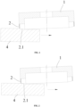
- a front ring works, and this mode is characterized in that an axial height at an outer circle of a working surface of a blade ring is lower than an axial height at an inner circle of the working surface of the blade ring, and the inner circle of the working surface of the blade ring is finally in contact with a workpiece.
- the second mode as shown in FIG. 3 and FIG.
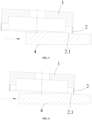
- a back ring works, and this mode is characterized in that the axial height at the outer circle of the working surface of the blade ring is higher than the axial height at the inner circle of the working surface of the blade ring, and the outer circle of the working surface of the blade ring is finally in contact with the workpiece.
- a third mode as shown in FIG. 5 , both the front ring and the back ring work, and this mode is characterized in that the axial height at the outer circle of the working surface of the blade ring is lower than the axial height at the inner circle of the working surface of the blade ring, and the inner circle of the working surface of the blade ring is finally in contact with the workpiece.
- an axial height difference between an outer diameter and an inner diameter of the grinding surface shows a curved surface form associated with the depth-of-cut.
- a through-blade ring-type cup-shaped grinding wheel of the prior art two adjacent blades are spaced apart to form a water passage channel capable of delivering cooling water to a working surface, and the water passage channel has a through structure in a radial direction of a blade ring.
- the cup-shaped grinding wheel rotates at a high speed, most of the cooling water entering the blade ring via an inner radial cavity will be thrown out toward the outer circle side of the blade ring via the water passage channel under a centrifugal force since the water passage channel has a through structure in the radial direction of the blade ring, such that the cooling effect on the working surface is extremely poor.
- the amount of cooling water flowing along the inner circle sidewall of the blade ring to the working surface of the blade ring is very small, and the water in a bundle state is easily atomized into small water droplets by an "airflow barrier", which attenuates the cooling effect. Therefore, a region of the working surface close to the inner circle of the blade ring has no cooling water or insufficient cooling water, failing to achieve sufficient cooling.
- an inner blade ring-type cup-shaped grinding wheel of the prior art the outer side of a blade ring is blocked, that is, an end of a water passage channel close to an outer circle of the blade ring is blocked.
- the cup-shaped grinding wheel rotates at a high speed, most of the cooling water entering an inner circle of the blade ring via an inner radial cavity will tend to gather at the end of the water passage channel close to the outer circle of the blade ring under a centrifugal force, and be thrown out from a region of the working surface close to the outer circle of the blade ring, and the region of the working surface close to the outer circle of the blade ring can be sufficiently cooled at this time.
- the region of the working surface close to the inner circle of the blade ring has no cooling water or insufficient cooling water, failing to achieve sufficient cooling.
- an object of the present invention is to provide a cooling structure of a high-speed cup-shaped wheel, in order to improve the cooling efficiency and the utilization efficiency of cooling water and advantageously improve the grinding stability and grinding quality.
- a cooling structure of a high-speed cup-shaped wheel includes a base and a blade ring, wherein the blade ring is arranged on the base and is fixedly connected to the base; the blade ring is provided with a plurality of water channel groups, which is sequentially arranged at intervals in a circumferential direction of the blade ring; and each of the water channel groups includes two or more inner water channels, which are sequentially arranged at intervals in the circumferential direction of the blade ring, the width of each of the two or more inner water channels in a radial direction of the blade ring being gradually increased.
- the present invention has the following beneficial effects: the cooling water flowing out of the two or more inner water channels different in width can cover the entire working surface, thereby improving the cooling efficiency for the working surface and avoiding the failure of sufficient cooling on some regions of the working surface; the cooling water covers the entire working surface, such that the utilization efficiency of the cooling water can be effectively improved; the influences from machining parameters can also be reduced to advantageously improve the grinding stability and grinding quality; and the cooling water covering the entire working surface can also allow the cup-shaped wheel to adapt to high-speed grinding.
- the present invention can implement further improvements as described below.
- a number of the inner water channels in each of the water channel groups has a directly proportional relationship with a depth-of-cut of the blade ring.
- the beneficial effect of adopting the above-mentioned further solution is that, with more inner water channels in each water channel group, the outflow uniformity of the cooling water is improved to ensure that the cooling water completely covers the entire working surface, thereby meeting the requirement of the cup-shaped wheel for high-speed machining and improving the cooling efficiency and cooling completeness.
- a width difference between two adjacent inner water channels in each of the water channel groups in the radial direction of the blade ring has an inversely proportional relationship with the number of the inner water channels.
- the beneficial effect of adopting the above-mentioned further solution is that when the cooling water is allowed to flow through the two or more inner water channels, the outer or inner circle edge of the blade ring can be covered with the cooling water to ensure that the cooling water completely covers the entire working surface, thereby meeting the requirement of the cup-shaped wheel for high-speed machining and improving the cooling efficiency and cooling completeness.
- each of the inner water channels in each of the water channel groups in the radial direction of the blade ring the larger a circumferential spacing between the inner water channel and the adjacent inner water channel thereof.
- the beneficial effect of adopting the above-mentioned further solution is that with larger circumferential spacing between adjacent inner water channels, the strength of the working surface corresponding to a region between two adjacent inner water channels is ensured, such that the cup-shaped wheel can adapt to high-speed grinding.
- a spacing between the inner water channel, having a maximum width in the radial direction of the blade ring, in each of the water channel groups and the adjacent inner water channel thereof is W1; a spacing between the inner water channel, having a minimum width in the radial direction of the blade ring, in the water channel group and the adjacent inner water channel thereof is W2; a spacing between the inner water channel, having the minimum width in the radial direction of the blade ring, in the water channel group and the inner water channel, having the maximum width in the radial direction of the blade ring, in the adjacent water channel group thereof is W3; and W1>W3>W2.
- the beneficial effect of adopting the above-mentioned further solution is that ensuring the strength of the working surface corresponding to the region between two adjacent inner water channels can further ensure the strength of the working surface corresponding to a region between two adjacent water channel groups, such that the cup-shaped wheel can adapt to high-speed grinding.
- a cooling coverage area between the inner water channel, having the maximum width in the radial direction of the blade ring, in each of the water channel groups and the adjacent inner water channel thereof is S1; a cooling coverage area between the inner water channel, having the minimum width in the radial direction of the blade ring, in the water channel group and the adjacent inner water channel thereof is S2; a cooling coverage area between the inner water channel, having the minimum width in the radial direction of the blade ring, in the water channel group and the inner water channel, having the maximum width in the radial direction of the blade ring, in the adjacent water channel group thereof is S3; and S1>S3>S2.
- the beneficial effect of adopting the above-mentioned further solution is that ensuring the strength of the working surface corresponding to the region between two adjacent inner water channels can further ensure the strength of the working surface corresponding to a region between two adjacent water channel groups, such that the cup-shaped wheel can adapt to high-speed grinding.
- the inner water channel, having the maximum width in the radial direction of the blade ring, in each of the water channel groups is close to an outer circle edge of the blade ring.
- the beneficial effect of adopting the above-mentioned further solution is that the cooling water flowing out of the inner water channel having the maximum width in the radial direction of the blade ring can cover the outer circle edge of the blade ring to improve the cooling efficiency.
- the two or more inner water channels each have a roundabout structure, and an axis of each of the two or more inner water channels deviates from a circle center of the blade ring.
- each of the water channel groups includes a water passage channel, which is arranged at a side of the inner water channel, having the largest length in the radial direction of the blade ring, in the water channel group.
- the beneficial effect of adopting the above-mentioned further solution is that the cooling water is thrown out via the water passage channels towards the outer circle of the blade ring, in order to cover the outer circle region of the blade ring, thereby improving the cooling efficiency of the blade ring.
- the water passage channel has a roundabout structure, and has an axis deviating from the circle center of the blade ring.
- a cooling structure of a high-speed cup-shaped wheel includes a base 1 and a blade ring 2.
- the blade ring 2 is arranged on the base 1 and fixedly connected to the base 1.
- the blade ring 2 is provided with a plurality of water channel groups 3, which is sequentially arranged at intervals in a circumferential direction of the blade ring 2.
- Each of the water channel groups 3 includes two or more inner water channels 3.1, which are sequentially arranged at intervals in the circumferential direction of the blade ring 2.
- the width of each of the two or more inner water channels 3.1 in a radial direction of the blade ring 2 is gradually increased.
- Cooling water is introduced at the center of the base 1 and enters the inner water channels 3.1. Under the action of a centrifugal force, the cooling water flows from the end of each inner water channel 3.1 close to the inner circle of the blade ring 2 to the end of the inner water channel 3.1 close to the outer circle of the blade ring 2. Because the end of the inner water channel 3.1 close to the outer circle of the blade ring 2 is blocked, the cooling water flows out to a working surface 2.1 of the blade ring 2, and flows on the working surface 2.1 along a tangential direction of the inner water channel 3.1, such that the cooling water cools a partial region of the working surface 2.1.
- each of the two or more inner water channels 3.1 in the radial direction of the blade ring 2 increases gradually, and the cooling water flowing out of the inner water channels 3.1 different in width can cover the entire working surface 2.1, thereby improving the cooling efficiency for the working surface 2.1 and avoiding the failure of sufficient cooling on some regions of the working surface 2.1; the cooling water covers the entire working surface 2.1, such that the utilization efficiency of the cooling water can be effectively improved; the influences from machining parameters can also be reduced to advantageously improve the grinding stability and grinding quality; and the cooling water covering the entire working surface 2.1 can also allow the cup-shaped wheel to adapt to high-speed grinding.
- One end of the inner water channel 3.1 is communicated to the inner circle of the blade ring 2, and the other end of the inner water channel 3.1 is close to the outer circle of the blade ring 2 and is blocked.
- the cooling structure is simple and is convenient to machine, and the cost can be effectively reduced.
- the number of the inner water channels 3.1 in each of the water channel groups 3 has a directly proportional relationship with a depth-of-cut of the blade ring 2.
- a width difference between two adjacent inner water channels 3.1 in each of the water channel groups 3 in the radial direction of the blade ring 2 has an inversely proportional relationship with the number of the inner water channels 3.1.
- the outer or inner circle edge of the blade ring 2 can be covered with the cooling water to ensure that the cooling water completely covers the entire working surface 2.1, thereby meeting the requirement of the cup-shaped wheel for high-speed machining and improving the cooling efficiency and cooling completeness.
- the strength of the working surface 2.1 corresponding to the region between the two adjacent inner water channels 3.1 is ensured, such that the cup-shaped wheel can adapt to high-speed grinding.
- W1 is also a circumferential distance between the inner water channel 3.1 having the maximum width in the radial direction of the blade ring 2 and the adjacent inner water channel 3.1 thereof;
- W2 is also a circumferential distance between the inner water channel 3.1 having the minimum width in the radial direction of the blade ring 2 and the adjacent inner water channel 3.1;
- W3 is also a circumferential distance between the inner water channel 3.1 having the minimum width in the radial direction of the blade ring 2 and the inner water channel 3.1, having the maximum width in the radial direction of the blade ring 2, in the adjacent water channel group 3.
- the strength of the working surface 2.1 corresponding to a region between the two adjacent inner water channels 3.1 is ensured, and the strength of the working surface 2.1 corresponding to a region between the two adjacent channel groups 3 is also ensured, such that the cup-shaped wheel can adapt to high-speed grinding.
- a cooling coverage area between the inner water channel 3.1, having the maximum width in the radial direction of the blade ring 2, in each of the water channel groups 3 and the adjacent inner water channel 3.1 thereof is S1;
- a cooling coverage area between the inner water channel 3.1, having the minimum width in the radial direction of the blade ring 2, in the water channel group 3 and the adjacent inner water channel 3.1 thereof is S2;
- a cooling coverage area between the inner water channel 3.1, having the minimum width in the radial direction of the blade ring 2, in the water channel group 3 and the inner water channel 3.1, having the maximum width in the radial direction of the blade ring 2, in the adjacent water channel group 3 thereof is S3; and S1>S3>S2.
- the inner water channel 3.1 having the maximum width in the radial direction of the blade ring 2, in each of the water channel groups 3 is close to an outer circle edge of the blade ring 2.
- the two or more inner water channels 3.1 each have a roundabout structure, and an axis of each of the two or more inner water channels 3.1 deviates from a circle center of the blade ring 2.
- a cooling structure of a high-speed cup-shaped wheel includes a base 1 and a blade ring 2.
- the blade ring 2 is arranged on the base 1 and fixedly connected to the base 1.
- the blade ring 2 is provided with a plurality of water channel groups 3, which is sequentially arranged at intervals in a circumferential direction of the blade ring 2.
- each of the two or more inner water channels 3.1 in the radial direction of the blade ring 2 increases gradually, and the cooling water flowing out of the inner water channels 3.1 different in width can cover the entire working surface 2.1, thereby improving the cooling efficiency for the working surface 2.1 and avoiding the failure of sufficient cooling on some regions of the working surface 2.1; the cooling water covers the entire working surface 2.1, such that the utilization efficiency of the cooling water can be effectively improved; the influences from machining parameters can also be reduced to advantageously improve the grinding stability and grinding quality; and the cooling water covering the entire working surface 2.1 can also allow the cup-shaped wheel to adapt to high-speed grinding.
- One end of the inner water channel 3.1 is communicated to the inner circle of the blade ring 2, and the other end of the inner water channel 3.1 is close to the outer circle of the blade ring 2 and is blocked.
- the cooling structure is simple and is convenient to machine, and the cost can be effectively reduced.
- the number of the inner water channels 3.1 in each of the water channel groups 3 has a directly proportional relationship with a depth-of-cut of the blade ring 2.
- a width difference between two adjacent inner water channels 3.1 in each of the water channel groups 3 in the radial direction of the blade ring 2 has an inversely proportional relationship with the number of the inner water channels 3.1.
- the width of the inner water channel 3.1, having the minimum width in the radial direction of the blade ring 2, in each of the water channel groups 3 is smaller. That is, the width of each inner water channel 3.1 in the radial direction of the blade ring 2 decreases with the increase of the depth-of-cut of the blade ring 2.
- the outer or inner circle edge of the blade ring 2 can be covered with the cooling water to ensure that the cooling water completely covers the entire working surface 2.1, thereby meeting the requirement of the cup-shaped wheel for high-speed machining and improving the cooling efficiency and cooling completeness.
- the strength of the working surface 2.1 corresponding to a region between the two adjacent inner water channels 3.1 is ensured, such that the cup-shaped wheel can adapt to high-speed grinding.
- the strength of the working surface 2.1 corresponding to the region between the two adjacent inner water channels 3.1 is ensured, and the strength of the working surface 2.1 corresponding to the region between the two adjacent channel groups 3 is also ensured, such that the cup-shaped wheel can adapt to high-speed grinding.
- a cooling coverage area between the inner water channel 3.1, having the maximum width in the radial direction of the blade ring 2, in each of the water channel groups 3 and the adjacent inner water channel 3.1 thereof is S1;
- a cooling coverage area between the inner water channel 3.1, having the minimum width in the radial direction of the blade ring 2, in the water channel group 3 and the adjacent inner water channel 3.1 thereof is S2;
- a cooling coverage area between the inner water channel 3.1, having the minimum width in the radial direction of the blade ring 2, in the water channel group 3 and the inner water channel 3.1, having the maximum width in the radial direction of the blade ring 2, in the adjacent water channel group 3 thereof is S3; and S1>S3>S2.
- the inner water channel 3.1 having the maximum width in the radial direction of the blade ring 2, in each of the water channel groups 3 is close to an outer circle edge of the blade ring 2.
- the end of the inner water channel 3.1, having the maximum width in the radial direction of the blade ring 2, close to the outer circle edge of the blade ring 2 is infinitely close to the outer circle edge of the blade ring 2 to allow that a spacing between the inner water channel 3.1 and the outer circle edge of the blade ring 2 is infinitely close to zero, such that the cooling water flowing out from the inner water channel 3.1, having the maximum width in the radial direction of the blade ring 2, can cover the outer circle edge of the blade ring 2, thereby improving the cooling efficiency.
- each of the water channel groups 3 includes a water passage channel 3.2, which is arranged at a side of the inner water channel 3.1, having the largest length in the radial direction of the blade ring 2, in the water channel group 3.
- the cooling water is introduced at the center of the base 1 and enters the water passage channels 3.2. Under the action of a centrifugal force, the cooling water is thrown out towards the outer circle side of the blade ring 2 to cover the outer circle region of the blade ring 2, thereby improving the cooling efficiency of the blade ring 2.
- the two or more inner water channels 3.1 each have a roundabout structure, and an axis of each of the two or more inner water channels 3.1 deviates from a circle center of the blade ring 2; and the water passage channel 3.2 has a roundabout structure, and has an axis deviating from the circle center of the blade ring 2.
- the two or more inner water channels 3.1 and the water passage channels 3.2 each have a roundabout structure, and an axis of each of the two or more inner water channels 3.1 and the water passage channels 3.2 deviates from the circle center of the blade ring 2.
Landscapes
- Engineering & Computer Science (AREA)
- Mechanical Engineering (AREA)
- Polishing Bodies And Polishing Tools (AREA)
- Auxiliary Devices For Machine Tools (AREA)
Description
- The present invention relates to the field of cup-shaped wheel technologies, and in particular to a cooling structure of a high-speed cup-shaped wheel (cf.
CN 205 588 162 U forming the basis for the preamble of claim 1). - A cup-shaped wheel mainly works in three major modes. In the first mode, as shown in
FIG. 1 and FIG. 2 , a front ring works, and this mode is characterized in that an axial height at an outer circle of a working surface of a blade ring is lower than an axial height at an inner circle of the working surface of the blade ring, and the inner circle of the working surface of the blade ring is finally in contact with a workpiece. In the second mode, as shown inFIG. 3 and FIG. 4 , a back ring works, and this mode is characterized in that the axial height at the outer circle of the working surface of the blade ring is higher than the axial height at the inner circle of the working surface of the blade ring, and the outer circle of the working surface of the blade ring is finally in contact with the workpiece. In a third mode, as shown inFIG. 5 , both the front ring and the back ring work, and this mode is characterized in that the axial height at the outer circle of the working surface of the blade ring is lower than the axial height at the inner circle of the working surface of the blade ring, and the inner circle of the working surface of the blade ring is finally in contact with the workpiece. After the running-in of the grinding surface of the blade ring in the three modes, with small variation in depth-of-cut and normal abrasion, an axial height difference between an outer diameter and an inner diameter of the grinding surface shows a curved surface form associated with the depth-of-cut. - In a through-blade ring-type cup-shaped grinding wheel of the prior art, two adjacent blades are spaced apart to form a water passage channel capable of delivering cooling water to a working surface, and the water passage channel has a through structure in a radial direction of a blade ring. When the cup-shaped grinding wheel rotates at a high speed, most of the cooling water entering the blade ring via an inner radial cavity will be thrown out toward the outer circle side of the blade ring via the water passage channel under a centrifugal force since the water passage channel has a through structure in the radial direction of the blade ring, such that the cooling effect on the working surface is extremely poor. Moreover, the amount of cooling water flowing along the inner circle sidewall of the blade ring to the working surface of the blade ring is very small, and the water in a bundle state is easily atomized into small water droplets by an "airflow barrier", which attenuates the cooling effect. Therefore, a region of the working surface close to the inner circle of the blade ring has no cooling water or insufficient cooling water, failing to achieve sufficient cooling.
- In an inner blade ring-type cup-shaped grinding wheel of the prior art, the outer side of a blade ring is blocked, that is, an end of a water passage channel close to an outer circle of the blade ring is blocked. When the cup-shaped grinding wheel rotates at a high speed, most of the cooling water entering an inner circle of the blade ring via an inner radial cavity will tend to gather at the end of the water passage channel close to the outer circle of the blade ring under a centrifugal force, and be thrown out from a region of the working surface close to the outer circle of the blade ring, and the region of the working surface close to the outer circle of the blade ring can be sufficiently cooled at this time. However, the region of the working surface close to the inner circle of the blade ring has no cooling water or insufficient cooling water, failing to achieve sufficient cooling.
- The present invention is intended to solve one of the above-mentioned technical problems in the prior art to some extent. To this end, an object of the present invention is to provide a cooling structure of a high-speed cup-shaped wheel, in order to improve the cooling efficiency and the utilization efficiency of cooling water and advantageously improve the grinding stability and grinding quality.
- The technical solution for the present invention to solve the above-mentioned technical problems is as follows. A cooling structure of a high-speed cup-shaped wheel includes a base and a blade ring, wherein the blade ring is arranged on the base and is fixedly connected to the base; the blade ring is provided with a plurality of water channel groups, which is sequentially arranged at intervals in a circumferential direction of the blade ring; and
each of the water channel groups includes two or more inner water channels, which are sequentially arranged at intervals in the circumferential direction of the blade ring, the width of each of the two or more inner water channels in a radial direction of the blade ring being gradually increased. - The present invention has the following beneficial effects: the cooling water flowing out of the two or more inner water channels different in width can cover the entire working surface, thereby improving the cooling efficiency for the working surface and avoiding the failure of sufficient cooling on some regions of the working surface; the cooling water covers the entire working surface, such that the utilization efficiency of the cooling water can be effectively improved; the influences from machining parameters can also be reduced to advantageously improve the grinding stability and grinding quality; and the cooling water covering the entire working surface can also allow the cup-shaped wheel to adapt to high-speed grinding.
- On the basis of the above-mentioned technical solution, the present invention can implement further improvements as described below.
- Further, a number of the inner water channels in each of the water channel groups has a directly proportional relationship with a depth-of-cut of the blade ring.
- The beneficial effect of adopting the above-mentioned further solution is that, with more inner water channels in each water channel group, the outflow uniformity of the cooling water is improved to ensure that the cooling water completely covers the entire working surface, thereby meeting the requirement of the cup-shaped wheel for high-speed machining and improving the cooling efficiency and cooling completeness.
- Further, a width difference between two adjacent inner water channels in each of the water channel groups in the radial direction of the blade ring has an inversely proportional relationship with the number of the inner water channels.
- The beneficial effect of adopting the above-mentioned further solution is that when the cooling water is allowed to flow through the two or more inner water channels, the outer or inner circle edge of the blade ring can be covered with the cooling water to ensure that the cooling water completely covers the entire working surface, thereby meeting the requirement of the cup-shaped wheel for high-speed machining and improving the cooling efficiency and cooling completeness.
- Further, the larger the width of each of the inner water channels in each of the water channel groups in the radial direction of the blade ring, the larger a circumferential spacing between the inner water channel and the adjacent inner water channel thereof.
- The beneficial effect of adopting the above-mentioned further solution is that with larger circumferential spacing between adjacent inner water channels, the strength of the working surface corresponding to a region between two adjacent inner water channels is ensured, such that the cup-shaped wheel can adapt to high-speed grinding.
- Further, a spacing between the inner water channel, having a maximum width in the radial direction of the blade ring, in each of the water channel groups and the adjacent inner water channel thereof is W1; a spacing between the inner water channel, having a minimum width in the radial direction of the blade ring, in the water channel group and the adjacent inner water channel thereof is W2; a spacing between the inner water channel, having the minimum width in the radial direction of the blade ring, in the water channel group and the inner water channel, having the maximum width in the radial direction of the blade ring, in the adjacent water channel group thereof is W3; and W1>W3>W2.
- The beneficial effect of adopting the above-mentioned further solution is that ensuring the strength of the working surface corresponding to the region between two adjacent inner water channels can further ensure the strength of the working surface corresponding to a region between two adjacent water channel groups, such that the cup-shaped wheel can adapt to high-speed grinding.
- Further, a cooling coverage area between the inner water channel, having the maximum width in the radial direction of the blade ring, in each of the water channel groups and the adjacent inner water channel thereof is S1; a cooling coverage area between the inner water channel, having the minimum width in the radial direction of the blade ring, in the water channel group and the adjacent inner water channel thereof is S2; a cooling coverage area between the inner water channel, having the minimum width in the radial direction of the blade ring, in the water channel group and the inner water channel, having the maximum width in the radial direction of the blade ring, in the adjacent water channel group thereof is S3; and S1>S3>S2.
- The beneficial effect of adopting the above-mentioned further solution is that ensuring the strength of the working surface corresponding to the region between two adjacent inner water channels can further ensure the strength of the working surface corresponding to a region between two adjacent water channel groups, such that the cup-shaped wheel can adapt to high-speed grinding.
- Further, the inner water channel, having the maximum width in the radial direction of the blade ring, in each of the water channel groups is close to an outer circle edge of the blade ring.
- The beneficial effect of adopting the above-mentioned further solution is that the cooling water flowing out of the inner water channel having the maximum width in the radial direction of the blade ring can cover the outer circle edge of the blade ring to improve the cooling efficiency.
- Further, the two or more inner water channels each have a roundabout structure, and an axis of each of the two or more inner water channels deviates from a circle center of the blade ring.
- Further, each of the water channel groups includes a water passage channel, which is arranged at a side of the inner water channel, having the largest length in the radial direction of the blade ring, in the water channel group.
- The beneficial effect of adopting the above-mentioned further solution is that the cooling water is thrown out via the water passage channels towards the outer circle of the blade ring, in order to cover the outer circle region of the blade ring, thereby improving the cooling efficiency of the blade ring.
- Further, the water passage channel has a roundabout structure, and has an axis deviating from the circle center of the blade ring.
-
-
FIG. 1 is a first schematic implementation diagram of a cup-shaped wheel in the prior art in a mode where a front ring works; -
FIG. 2 is a second schematic implementation diagram of the cup-shaped wheel in the prior art in a mode where the front ring works; -
FIG. 3 is a first schematic implementation diagram of the cup-shaped wheel in the prior art in a mode where a back ring works; -
FIG. 4 is a second schematic implementation diagram of the cup-shaped wheel in the prior art in a mode where the back ring works; -
FIG. 5 is a schematic implementation diagram of the cup-shaped wheel of the prior art in a mode where both the front ring and the back ring work; -
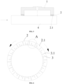
FIG. 6 is a front view of a cup-shaped wheel with respect toEmbodiment 1 according to the present invention; -
FIG. 7 is a schematic enlarged view of Part A inFIG. 6 ; -
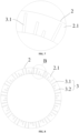
FIG. 8 is a front view of a cup-shaped wheel with respect toEmbodiment 2 according to the present invention; and -
FIG. 9 is a schematic enlarged view of Part B inFIG. 8 . - In the accompanying drawings, components represented by respective reference numerals are listed below:
- 1, base;
- 2, blade ring; 2.1, working surface;
- 3, water channel group; 3.1, inner water channel; 3.2, water passage channel; and
- 4, workpiece.
- The principles and features of the present invention will be described below in conjunction with the accompanying drawings. The examples are only used to explain the present invention only, and are not intended to limit the scope of the present invention.
- As shown in
FIG. 6 andFIG. 7 , a cooling structure of a high-speed cup-shaped wheel includes abase 1 and ablade ring 2. Theblade ring 2 is arranged on thebase 1 and fixedly connected to thebase 1. Theblade ring 2 is provided with a plurality ofwater channel groups 3, which is sequentially arranged at intervals in a circumferential direction of theblade ring 2. - Each of the
water channel groups 3 includes two or more inner water channels 3.1, which are sequentially arranged at intervals in the circumferential direction of theblade ring 2. The width of each of the two or more inner water channels 3.1 in a radial direction of theblade ring 2 is gradually increased. - Cooling water is introduced at the center of the
base 1 and enters the inner water channels 3.1. Under the action of a centrifugal force, the cooling water flows from the end of each inner water channel 3.1 close to the inner circle of theblade ring 2 to the end of the inner water channel 3.1 close to the outer circle of theblade ring 2. Because the end of the inner water channel 3.1 close to the outer circle of theblade ring 2 is blocked, the cooling water flows out to a working surface 2.1 of theblade ring 2, and flows on the working surface 2.1 along a tangential direction of the inner water channel 3.1, such that the cooling water cools a partial region of the working surface 2.1. - The width of each of the two or more inner water channels 3.1 in the radial direction of the
blade ring 2 increases gradually, and the cooling water flowing out of the inner water channels 3.1 different in width can cover the entire working surface 2.1, thereby improving the cooling efficiency for the working surface 2.1 and avoiding the failure of sufficient cooling on some regions of the working surface 2.1; the cooling water covers the entire working surface 2.1, such that the utilization efficiency of the cooling water can be effectively improved; the influences from machining parameters can also be reduced to advantageously improve the grinding stability and grinding quality; and the cooling water covering the entire working surface 2.1 can also allow the cup-shaped wheel to adapt to high-speed grinding. - One end of the inner water channel 3.1 is communicated to the inner circle of the
blade ring 2, and the other end of the inner water channel 3.1 is close to the outer circle of theblade ring 2 and is blocked. The cooling structure is simple and is convenient to machine, and the cost can be effectively reduced. - In the above-mentioned embodiment, the number of the inner water channels 3.1 in each of the
water channel groups 3 has a directly proportional relationship with a depth-of-cut of theblade ring 2. - That is, the larger the depth-of-cut of the
blade ring 2 of the cup-shaped wheel, the more the inner water channels 3.1 in each of thewater channel groups 3, such that the outflow uniformity of the cooling water is improved to ensure that the cooling water completely covers the entire working surface 2.1, thereby meeting the requirement of the cup-shaped wheel for high-speed machining and improving the cooling efficiency and cooling completeness. - In the above-mentioned embodiment, a width difference between two adjacent inner water channels 3.1 in each of the
water channel groups 3 in the radial direction of theblade ring 2 has an inversely proportional relationship with the number of the inner water channels 3.1. - That is, when the depth-of-cut of the
blade ring 2 of the cup-shaped wheel becomes larger, the more the inner water channels 3.1 in each of thewater channel groups 3, the smaller the width difference, in the radial direction of theblade ring 2, between two adjacent inner water channels 3.1. However, the inner water channel 3.1, having the minimum width in the radial direction of theblade ring 2, in each of thewater channel groups 3 is smaller. That is, the width of each inner water channel 3.1 in the radial direction of theblade ring 2 decreases with the increase of the depth-of-cut of theblade ring 2. - When the cooling water is allowed to flow through two or more inner water channels 3.1, the outer or inner circle edge of the
blade ring 2 can be covered with the cooling water to ensure that the cooling water completely covers the entire working surface 2.1, thereby meeting the requirement of the cup-shaped wheel for high-speed machining and improving the cooling efficiency and cooling completeness. - In the above-mentioned embodiment, the larger the width of each of the inner water channels 3.1 in each of the
water channel groups 3 in the radial direction of theblade ring 2, the larger a circumferential spacing between the inner water channel and the adjacent inner water channel 3.1 thereof. - With a larger circumferential spacing between adjacent inner water channels 3.1, the strength of the working surface 2.1 corresponding to the region between the two adjacent inner water channels 3.1 is ensured, such that the cup-shaped wheel can adapt to high-speed grinding.
- In the above-mentioned embodiment, a spacing between the inner water channel 3.1, having a maximum width in the radial direction of the
blade ring 2, in each of thewater channel groups 3 and the adjacent inner water channel 3.1 thereof is W1; a spacing between the inner water channel 3.1, having a minimum width in the radial direction of theblade ring 2, in thewater channel group 3 and the adjacent inner water channel 3.1 thereof is W2; a spacing between the inner water channel 3.1, having the minimum width in the radial direction of theblade ring 2, in thewater channel group 3 and the inner water channel 3.1, having the maximum width in the radial direction of theblade ring 2, in the adjacentwater channel group 3 thereof is W3; and W1>W3>W2. - W1 is also a circumferential distance between the inner water channel 3.1 having the maximum width in the radial direction of the
blade ring 2 and the adjacent inner water channel 3.1 thereof; W2 is also a circumferential distance between the inner water channel 3.1 having the minimum width in the radial direction of theblade ring 2 and the adjacent inner water channel 3.1; and W3 is also a circumferential distance between the inner water channel 3.1 having the minimum width in the radial direction of theblade ring 2 and the inner water channel 3.1, having the maximum width in the radial direction of theblade ring 2, in the adjacentwater channel group 3. - By setting W1>W3>W2, the strength of the working surface 2.1 corresponding to a region between the two adjacent inner water channels 3.1 is ensured, and the strength of the working surface 2.1 corresponding to a region between the two
adjacent channel groups 3 is also ensured, such that the cup-shaped wheel can adapt to high-speed grinding. - In the above-mentioned embodiment, a cooling coverage area between the inner water channel 3.1, having the maximum width in the radial direction of the
blade ring 2, in each of thewater channel groups 3 and the adjacent inner water channel 3.1 thereof is S1; a cooling coverage area between the inner water channel 3.1, having the minimum width in the radial direction of theblade ring 2, in thewater channel group 3 and the adjacent inner water channel 3.1 thereof is S2; a cooling coverage area between the inner water channel 3.1, having the minimum width in the radial direction of theblade ring 2, in thewater channel group 3 and the inner water channel 3.1, having the maximum width in the radial direction of theblade ring 2, in the adjacentwater channel group 3 thereof is S3; and S1>S3>S2. - By setting S1>S3>S2, the strength of the working surface 2.1 corresponding to the region between the two adjacent inner water channels 3.1 is ensured, and the strength of the working surface 2.1 corresponding to the region between the two
adjacent channel groups 3 is also ensured, such that the cup-shaped wheel can adapt to high-speed grinding. - In the above-mentioned embodiment, the inner water channel 3.1, having the maximum width in the radial direction of the
blade ring 2, in each of thewater channel groups 3 is close to an outer circle edge of theblade ring 2. - The end of the inner water channel 3.1, having the maximum width in the radial direction of the
blade ring 2, close to the outer circle edge of theblade ring 2 is infinitely close to the outer circle edge of theblade ring 2 to allow that a spacing between the inner water channel 3.1 and the outer circle edge of theblade ring 2 is infinitely close to zero, such that the cooling water flowing out from the inner water channel 3.1, having the maximum width in the radial direction of theblade ring 2, can cover the outer circle edge of theblade ring 2, thereby improving the cooling efficiency. - In the above-mentioned embodiment, the two or more inner water channels 3.1 each have a roundabout structure, and an axis of each of the two or more inner water channels 3.1 deviates from a circle center of the
blade ring 2. - As shown in
FIG.6 , when the cooling structure of the high-speed cup-shaped wheel in this embodiment rotates counterclockwise, the strength of theblade ring 2 can be improved favorably; and when the cooling structure of the high-speed cup-shaped wheel rotates clockwise, the utilization ratio of the cooling water can be increased favorably. - As shown in
FIG. 8 andFIG. 9 , a cooling structure of a high-speed cup-shaped wheel includes abase 1 and ablade ring 2. Theblade ring 2 is arranged on thebase 1 and fixedly connected to thebase 1. Theblade ring 2 is provided with a plurality ofwater channel groups 3, which is sequentially arranged at intervals in a circumferential direction of theblade ring 2. - Each of the
water channel groups 3 includes two or more inner water channels 3.1, which are sequentially arranged at intervals in the circumferential direction of theblade ring 2. The width of each of the two or more inner water channels 3.1 in a radial direction of theblade ring 2 is gradually increased. - Cooling water is introduced at the center of the
base 1 and enters the inner water channels 3.1. Under the action of a centrifugal force, the cooling water flows from the end of each inner water channel 3.1 close to the inner circle of theblade ring 2 to the end of the inner water channel 3.1 close to the outer circle of theblade ring 2. Because the end of the inner water channel 3.1 close to the outer circle of theblade ring 2 is blocked, the cooling water flows out to a working surface 2.1 of theblade ring 2, and flows on the working surface 2.1 along a tangential direction of the inner water channel 3.1, such that the cooling water cools a partial region on the working surface 2.1. - The width of each of the two or more inner water channels 3.1 in the radial direction of the
blade ring 2 increases gradually, and the cooling water flowing out of the inner water channels 3.1 different in width can cover the entire working surface 2.1, thereby improving the cooling efficiency for the working surface 2.1 and avoiding the failure of sufficient cooling on some regions of the working surface 2.1; the cooling water covers the entire working surface 2.1, such that the utilization efficiency of the cooling water can be effectively improved; the influences from machining parameters can also be reduced to advantageously improve the grinding stability and grinding quality; and the cooling water covering the entire working surface 2.1 can also allow the cup-shaped wheel to adapt to high-speed grinding. - One end of the inner water channel 3.1 is communicated to the inner circle of the
blade ring 2, and the other end of the inner water channel 3.1 is close to the outer circle of theblade ring 2 and is blocked. The cooling structure is simple and is convenient to machine, and the cost can be effectively reduced. - In the above-mentioned embodiment, the number of the inner water channels 3.1 in each of the
water channel groups 3 has a directly proportional relationship with a depth-of-cut of theblade ring 2. - That is, the larger the depth-of-cut of the
blade ring 2 of the cup-shaped wheel, the more the inner water channels 3.1 in each of thewater channel groups 3, such that the outflow uniformity of the cooling water is improved to ensure that the cooling water completely covers the entire working surface 2.1, thereby meeting the requirement of the cup-shaped wheel for high-speed machining and improving the cooling efficiency and cooling completeness. - In the above-mentioned embodiment, a width difference between two adjacent inner water channels 3.1 in each of the
water channel groups 3 in the radial direction of theblade ring 2 has an inversely proportional relationship with the number of the inner water channels 3.1. - That is, when the depth-of-cut of the
blade ring 2 of the cup-shaped wheel becomes larger, the more the inner water channels 3.1 in each of thewater channel groups 3, the smaller the width difference, in the radial direction of theblade ring 2, between two adjacent inner water channels 3.1. However, the width of the inner water channel 3.1, having the minimum width in the radial direction of theblade ring 2, in each of thewater channel groups 3 is smaller. That is, the width of each inner water channel 3.1 in the radial direction of theblade ring 2 decreases with the increase of the depth-of-cut of theblade ring 2. - When the cooling water is allowed to flow through two or more inner water channels 3.1, the outer or inner circle edge of the
blade ring 2 can be covered with the cooling water to ensure that the cooling water completely covers the entire working surface 2.1, thereby meeting the requirement of the cup-shaped wheel for high-speed machining and improving the cooling efficiency and cooling completeness. - In the above-mentioned embodiment, the larger the width of each of the inner water channels 3.1 in each of the
water channel groups 3 in the radial direction of theblade ring 2, the larger a circumferential spacing between the inner water channel and the adjacent inner water channel 3.1 thereof. - With a larger circumferential spacing between adjacent inner water channels 3.1, the strength of the working surface 2.1 corresponding to a region between the two adjacent inner water channels 3.1 is ensured, such that the cup-shaped wheel can adapt to high-speed grinding.
- In the above-mentioned embodiment, a spacing between the inner water channel 3.1, having a maximum width in the radial direction of the
blade ring 2, in each of thewater channel groups 3 and the adjacent inner water channel 3.1 thereof is W1; a spacing between the inner water channel 3.1, having a minimum width in the radial direction of theblade ring 2, in thewater channel group 3 and the adjacent inner water channel 3.1 thereof is W2; a spacing between the inner water channel 3.1, having the minimum width in the radial direction of theblade ring 2, in thewater channel group 3 and the inner water channel 3.1, having the maximum width in the radial direction of theblade ring 2, in the adjacentwater channel group 3 thereof is W3; and W1>W3>W2. - By setting W1>W3>W2, the strength of the working surface 2.1 corresponding to the region between the two adjacent inner water channels 3.1 is ensured, and the strength of the working surface 2.1 corresponding to the region between the two
adjacent channel groups 3 is also ensured, such that the cup-shaped wheel can adapt to high-speed grinding. - In the above-mentioned embodiment, a cooling coverage area between the inner water channel 3.1, having the maximum width in the radial direction of the
blade ring 2, in each of thewater channel groups 3 and the adjacent inner water channel 3.1 thereof is S1; a cooling coverage area between the inner water channel 3.1, having the minimum width in the radial direction of theblade ring 2, in thewater channel group 3 and the adjacent inner water channel 3.1 thereof is S2; a cooling coverage area between the inner water channel 3.1, having the minimum width in the radial direction of theblade ring 2, in thewater channel group 3 and the inner water channel 3.1, having the maximum width in the radial direction of theblade ring 2, in the adjacentwater channel group 3 thereof is S3; and S1>S3>S2. - By setting S1>S3>S2, the strength of the working surface 2.1 corresponding to the region between the two adjacent inner water channels 3.1 is ensured, and the strength of the working surface 2.1 corresponding to the region between the two
adjacent channel groups 3 is also ensured, such that the cup-shaped wheel can adapt to high-speed grinding. - In the above-mentioned embodiment, the inner water channel 3.1, having the maximum width in the radial direction of the
blade ring 2, in each of thewater channel groups 3 is close to an outer circle edge of theblade ring 2. - The end of the inner water channel 3.1, having the maximum width in the radial direction of the
blade ring 2, close to the outer circle edge of theblade ring 2 is infinitely close to the outer circle edge of theblade ring 2 to allow that a spacing between the inner water channel 3.1 and the outer circle edge of theblade ring 2 is infinitely close to zero, such that the cooling water flowing out from the inner water channel 3.1, having the maximum width in the radial direction of theblade ring 2, can cover the outer circle edge of theblade ring 2, thereby improving the cooling efficiency. - In the above-mentioned embodiment, each of the
water channel groups 3 includes a water passage channel 3.2, which is arranged at a side of the inner water channel 3.1, having the largest length in the radial direction of theblade ring 2, in thewater channel group 3. - The cooling water is introduced at the center of the
base 1 and enters the water passage channels 3.2. Under the action of a centrifugal force, the cooling water is thrown out towards the outer circle side of theblade ring 2 to cover the outer circle region of theblade ring 2, thereby improving the cooling efficiency of theblade ring 2. - In the above-mentioned embodiment, the two or more inner water channels 3.1 each have a roundabout structure, and an axis of each of the two or more inner water channels 3.1 deviates from a circle center of the
blade ring 2; and the water passage channel 3.2 has a roundabout structure, and has an axis deviating from the circle center of theblade ring 2. - The two or more inner water channels 3.1 and the water passage channels 3.2 each have a roundabout structure, and an axis of each of the two or more inner water channels 3.1 and the water passage channels 3.2 deviates from the circle center of the
blade ring 2. - Described above are merely preferred embodiments of the present invention, which are not intended to limit the present invention. The scope of protection is determined by the appended claims.
Claims (10)
- A cooling structure of a high-speed cup-shaped wheel, comprising a base (1) and a blade ring (2), the blade ring (2) being arranged on the base (1) and fixedly connected to the base (1), wherein the blade ring (2) is provided with a plurality of water channel groups (3), which is sequentially arranged at intervals in a circumferential direction of the blade ring (2); and characterised in that each of the water channel groups (3) comprises two or more inner water channels (3.1), which are sequentially arranged at intervals in the circumferential direction of the blade ring (2), the width of each of the two or more inner water channels (3.1) in a radial direction of the blade ring (2) being gradually increased.
- The cooling structure of the high-speed cup-shaped wheel according to claim 1, wherein a number of the inner water channels (3.1) in each of the water channel groups (3) has a directly proportional relationship with a depth-of-cut of the blade ring (2).
- The cooling structure of the high-speed cup-shaped wheel according to claim 2, wherein a width difference between two adjacent inner water channels (3.1) in each of the water channel groups (3) in the radial direction of the blade ring (2) has an inversely proportional relationship with the number of the inner water channels (3.1).
- The cooling structure of the high-speed cup-shaped wheel according to claim 3, wherein the larger the width of each of the inner water channels (3.1) in each of the water channel groups (3) in the radial direction of the blade ring (2), the larger a circumferential spacing between the inner water channel (3.1) and the adjacent inner water channel (3.1) thereof.
- The cooling structure of the high-speed cup-shaped wheel according to claim 4, wherein a spacing between the inner water channel (3.1), having a maximum width in the radial direction of the blade ring (2), in each of the water channel groups (3) and the adjacent inner water channel (3.1) thereof is W1; a spacing between the inner water channel (3.1), having a minimum width in the radial direction of the blade ring (2), in the water channel group (3) and the adjacent inner water channel (3.1) thereof is W2; a spacing between the inner water channel (3.1), having the minimum width in the radial direction of the blade ring (2), in the water channel group (3) and the inner water channel (3.1), having the maximum width in the radial direction of the blade ring (2), in the adjacent water channel group (3) thereof is W3; and W1>W3>W2.
- The cooling structure of the high-speed cup-shaped wheel according to claim 4, wherein a cooling coverage area between the inner water channel (3.1), having the maximum width in the radial direction of the blade ring (2), in each of the water channel groups (3) and the adjacent inner water channel (3.1) thereof is S1; a cooling coverage area between the inner water channel (3.1), having the minimum width in the radial direction of the blade ring (2), in the water channel group (3) and the adjacent inner water channel (3.1) thereof is S2; a cooling coverage area between the inner water channel (3.1), having the minimum width in the radial direction of the blade ring (2), in the water channel group (3) and the inner water channel (3.1), having the maximum width in the radial direction of the blade ring (2), in the adjacent water channel group (3) thereof is S3; and S1>S3>S2.
- The cooling structure of the high-speed cup-shaped wheel according to claim 1, wherein the inner water channel (3.1), having the maximum width in the radial direction of the blade ring (2), in each of the water channel groups (3) is close to an outer circle edge of the blade ring (2).
- The cooling structure of the high-speed cup-shaped wheel according to claim 1, wherein the two or more inner water channels (3.1) each have a roundabout structure, and an axis of each of the two or more inner water channels (3.1) deviates from a circle center of the blade ring (2).
- The cooling structure of the high-speed cup-shaped wheel according to any one of claims 1 to 8, wherein each of the water channel groups (3) comprises a water passage channel (3.2), which is arranged at a side of the inner water channel (3.1), having the largest length in the radial direction of the blade ring (2), in the water channel group (3).
- The cooling structure of the high-speed cup-shaped wheel according to claim 9, wherein the water passage channel (3.2) has a roundabout structure, and has an axis deviating from the circle center of the blade ring (2).
Applications Claiming Priority (3)
| Application Number | Priority Date | Filing Date | Title |
|---|---|---|---|
| CN202010796438.0A CN111958508B (en) | 2020-08-10 | 2020-08-10 | A high-speed cup wheel cooling structure |
| CN202021645795.9U CN212218225U (en) | 2020-08-10 | 2020-08-10 | High-speed cup-shaped wheel cooling structure |
| PCT/CN2021/110855 WO2022033386A1 (en) | 2020-08-10 | 2021-08-05 | High-speed cup-shaped wheel cooling structure |
Publications (3)
| Publication Number | Publication Date |
|---|---|
| EP4194146A1 EP4194146A1 (en) | 2023-06-14 |
| EP4194146A4 EP4194146A4 (en) | 2024-08-21 |
| EP4194146B1 true EP4194146B1 (en) | 2025-03-05 |
Family
ID=80247716
Family Applications (1)
| Application Number | Title | Priority Date | Filing Date |
|---|---|---|---|
| EP21855439.2A Active EP4194146B1 (en) | 2020-08-10 | 2021-08-05 | High-speed cup-shaped wheel cooling structure |
Country Status (5)
| Country | Link |
|---|---|
| US (1) | US20230294245A1 (en) |
| EP (1) | EP4194146B1 (en) |
| JP (1) | JP7514578B2 (en) |
| KR (1) | KR102700968B1 (en) |
| WO (1) | WO2022033386A1 (en) |
Families Citing this family (2)
| Publication number | Priority date | Publication date | Assignee | Title |
|---|---|---|---|---|
| CN111438643B (en) * | 2020-03-30 | 2024-05-14 | 桂林创源金刚石有限公司 | A high speed cup grinding wheel |
| EP4194146B1 (en) * | 2020-08-10 | 2025-03-05 | Guilin Champion Union Diamond Co., Ltd. | High-speed cup-shaped wheel cooling structure |
Family Cites Families (17)
| Publication number | Priority date | Publication date | Assignee | Title |
|---|---|---|---|---|
| JPS5746116Y2 (en) * | 1979-12-05 | 1982-10-12 | ||
| JPH0171061U (en) * | 1987-10-29 | 1989-05-11 | ||
| DE19704746A1 (en) * | 1997-02-08 | 1998-08-20 | August Heinr Schmidt Gmbh & Co | Grinding disc for machining workpieces |
| JPH11179667A (en) * | 1997-12-18 | 1999-07-06 | Asahi Diamond Ind Co Ltd | Cup type wheel |
| JPH11245169A (en) * | 1998-02-27 | 1999-09-14 | Asahi Diamond Ind Co Ltd | Cup type wheel |
| JP2001062736A (en) * | 1999-08-24 | 2001-03-13 | Asahi Diamond Industrial Co Ltd | Cup type wheel and manufacturing method thereof |
| KR20110060380A (en) * | 2009-11-30 | 2011-06-08 | 오동석 | Diamond tools |
| CN203738615U (en) * | 2014-02-28 | 2014-07-30 | 自贡硬质合金有限责任公司 | Grinding wheel for parallel surface grinding machine |
| CN205588162U (en) * | 2016-05-10 | 2016-09-21 | 桂林创源金刚石有限公司 | Lead to cup -shaped edging emery wheel of diamond that tooth and internal tooth combine |
| TW201841857A (en) * | 2017-01-24 | 2018-12-01 | 美商康寧公司 | Methods and apparatus for finishing edges of glass sheets |
| JP6948798B2 (en) * | 2017-02-14 | 2021-10-13 | 株式会社ディスコ | Grinding wheel |
| JP7227754B2 (en) * | 2018-12-12 | 2023-02-22 | 株式会社ディスコ | Grinding equipment |
| CN111438643B (en) * | 2020-03-30 | 2024-05-14 | 桂林创源金刚石有限公司 | A high speed cup grinding wheel |
| CN111958508B (en) * | 2020-08-10 | 2025-04-01 | 桂林创源金刚石有限公司 | A high-speed cup wheel cooling structure |
| EP4194146B1 (en) * | 2020-08-10 | 2025-03-05 | Guilin Champion Union Diamond Co., Ltd. | High-speed cup-shaped wheel cooling structure |
| CN112828782A (en) * | 2021-02-08 | 2021-05-25 | 宋京新 | A high-speed polishing wheel |
| JP6945903B1 (en) * | 2021-03-04 | 2021-10-06 | オオノ開發株式会社 | Machining tools and machining equipment using those machining tools |
-
2021
- 2021-08-05 EP EP21855439.2A patent/EP4194146B1/en active Active
- 2021-08-05 KR KR1020237000485A patent/KR102700968B1/en active Active
- 2021-08-05 US US18/017,089 patent/US20230294245A1/en not_active Abandoned
- 2021-08-05 JP JP2023501139A patent/JP7514578B2/en active Active
- 2021-08-05 WO PCT/CN2021/110855 patent/WO2022033386A1/en not_active Ceased
Also Published As
| Publication number | Publication date |
|---|---|
| KR102700968B1 (en) | 2024-09-02 |
| JP7514578B2 (en) | 2024-07-11 |
| US20230294245A1 (en) | 2023-09-21 |
| KR20230034292A (en) | 2023-03-09 |
| EP4194146A1 (en) | 2023-06-14 |
| EP4194146A4 (en) | 2024-08-21 |
| JP2023532777A (en) | 2023-07-31 |
| WO2022033386A1 (en) | 2022-02-17 |
Similar Documents
| Publication | Publication Date | Title |
|---|---|---|
| EP4194146A1 (en) | High-speed cup-shaped wheel cooling structure | |
| US12220789B2 (en) | High-rotational speed cup-shaped grinding wheel | |
| CN111958508B (en) | A high-speed cup wheel cooling structure | |
| US11933314B2 (en) | Compressor wheel | |
| EP4151364B1 (en) | Special-shaped wheel having positive correlation water passing structure for full-grinding surface | |
| EP4023393A1 (en) | Tool cooling mechanism | |
| CN212218225U (en) | High-speed cup-shaped wheel cooling structure | |
| JP2023532777A5 (en) | ||
| KR101415159B1 (en) | Grinding wheel | |
| CN215847689U (en) | Composite structure cup-shaped grinding wheel | |
| US20190299479A1 (en) | Round knife with concentric material rejuvenation | |
| US20160346903A1 (en) | Cutting Disk | |
| CN211540892U (en) | Grinding wheel | |
| KR101164498B1 (en) | Grinding wheel | |
| GB2437933A (en) | Machining tool with internal fluid delivery system | |
| CN221186056U (en) | Ceramic processing grinding wheel | |
| CN210909605U (en) | Novel cymbal type grinding wheel | |
| CN222464262U (en) | Baffle structure, rotor structure, motor and vehicle | |
| EP2788139A1 (en) | Disk mill and method | |
| CN211386948U (en) | Centerless lathe chip blocking disc | |
| CN114274062A (en) | Grinding head for processing surface of silicon wafer and grinding method thereof | |
| JPH0375310B2 (en) | ||
| KR20220050327A (en) | Apparatus fot CBN grinding wheel | |
| WO2024140373A1 (en) | Composite function pressing plate for semiconductor scribing blade | |
| CN120419078A (en) | Rotor assembly for an electric machine, electric machine and method for cooling a rotor |
Legal Events
| Date | Code | Title | Description |
|---|---|---|---|
| STAA | Information on the status of an ep patent application or granted ep patent |
Free format text: STATUS: THE INTERNATIONAL PUBLICATION HAS BEEN MADE |
|
| PUAI | Public reference made under article 153(3) epc to a published international application that has entered the european phase |
Free format text: ORIGINAL CODE: 0009012 |
|
| STAA | Information on the status of an ep patent application or granted ep patent |
Free format text: STATUS: REQUEST FOR EXAMINATION WAS MADE |
|
| 17P | Request for examination filed |
Effective date: 20230227 |
|
| AK | Designated contracting states |
Kind code of ref document: A1 Designated state(s): AL AT BE BG CH CY CZ DE DK EE ES FI FR GB GR HR HU IE IS IT LI LT LU LV MC MK MT NL NO PL PT RO RS SE SI SK SM TR |
|
| DAV | Request for validation of the european patent (deleted) | ||
| DAX | Request for extension of the european patent (deleted) | ||
| A4 | Supplementary search report drawn up and despatched |
Effective date: 20240722 |
|
| RIC1 | Information provided on ipc code assigned before grant |
Ipc: B24D 13/18 20060101ALI20240716BHEP Ipc: B24D 5/10 20060101ALI20240716BHEP Ipc: B24D 7/10 20060101AFI20240716BHEP |
|
| GRAP | Despatch of communication of intention to grant a patent |
Free format text: ORIGINAL CODE: EPIDOSNIGR1 |
|
| STAA | Information on the status of an ep patent application or granted ep patent |
Free format text: STATUS: GRANT OF PATENT IS INTENDED |
|
| INTG | Intention to grant announced |
Effective date: 20241122 |
|
| GRAS | Grant fee paid |
Free format text: ORIGINAL CODE: EPIDOSNIGR3 |
|
| GRAA | (expected) grant |
Free format text: ORIGINAL CODE: 0009210 |
|
| STAA | Information on the status of an ep patent application or granted ep patent |
Free format text: STATUS: THE PATENT HAS BEEN GRANTED |
|
| AK | Designated contracting states |
Kind code of ref document: B1 Designated state(s): AL AT BE BG CH CY CZ DE DK EE ES FI FR GB GR HR HU IE IS IT LI LT LU LV MC MK MT NL NO PL PT RO RS SE SI SK SM TR |
|
| REG | Reference to a national code |
Ref country code: GB Ref legal event code: FG4D |
|
| REG | Reference to a national code |
Ref country code: CH Ref legal event code: EP |
|
| REG | Reference to a national code |
Ref country code: IE Ref legal event code: FG4D |
|
| REG | Reference to a national code |
Ref country code: DE Ref legal event code: R096 Ref document number: 602021027306 Country of ref document: DE |
|
| PG25 | Lapsed in a contracting state [announced via postgrant information from national office to epo] |
Ref country code: RS Free format text: LAPSE BECAUSE OF FAILURE TO SUBMIT A TRANSLATION OF THE DESCRIPTION OR TO PAY THE FEE WITHIN THE PRESCRIBED TIME-LIMIT Effective date: 20250605 |
|
| PG25 | Lapsed in a contracting state [announced via postgrant information from national office to epo] |
Ref country code: FI Free format text: LAPSE BECAUSE OF FAILURE TO SUBMIT A TRANSLATION OF THE DESCRIPTION OR TO PAY THE FEE WITHIN THE PRESCRIBED TIME-LIMIT Effective date: 20250305 |
|
| REG | Reference to a national code |
Ref country code: NL Ref legal event code: MP Effective date: 20250305 |
|
| PG25 | Lapsed in a contracting state [announced via postgrant information from national office to epo] |
Ref country code: ES Free format text: LAPSE BECAUSE OF FAILURE TO SUBMIT A TRANSLATION OF THE DESCRIPTION OR TO PAY THE FEE WITHIN THE PRESCRIBED TIME-LIMIT Effective date: 20250305 |
|
| REG | Reference to a national code |
Ref country code: LT Ref legal event code: MG9D |
|
| PG25 | Lapsed in a contracting state [announced via postgrant information from national office to epo] |
Ref country code: NO Free format text: LAPSE BECAUSE OF FAILURE TO SUBMIT A TRANSLATION OF THE DESCRIPTION OR TO PAY THE FEE WITHIN THE PRESCRIBED TIME-LIMIT Effective date: 20250605 |
|
| PG25 | Lapsed in a contracting state [announced via postgrant information from national office to epo] |
Ref country code: HR Free format text: LAPSE BECAUSE OF FAILURE TO SUBMIT A TRANSLATION OF THE DESCRIPTION OR TO PAY THE FEE WITHIN THE PRESCRIBED TIME-LIMIT Effective date: 20250305 |
|
| PG25 | Lapsed in a contracting state [announced via postgrant information from national office to epo] |
Ref country code: LV Free format text: LAPSE BECAUSE OF FAILURE TO SUBMIT A TRANSLATION OF THE DESCRIPTION OR TO PAY THE FEE WITHIN THE PRESCRIBED TIME-LIMIT Effective date: 20250305 |
|
| PG25 | Lapsed in a contracting state [announced via postgrant information from national office to epo] |
Ref country code: BG Free format text: LAPSE BECAUSE OF FAILURE TO SUBMIT A TRANSLATION OF THE DESCRIPTION OR TO PAY THE FEE WITHIN THE PRESCRIBED TIME-LIMIT Effective date: 20250305 Ref country code: GR Free format text: LAPSE BECAUSE OF FAILURE TO SUBMIT A TRANSLATION OF THE DESCRIPTION OR TO PAY THE FEE WITHIN THE PRESCRIBED TIME-LIMIT Effective date: 20250606 |
|
| REG | Reference to a national code |
Ref country code: AT Ref legal event code: MK05 Ref document number: 1772512 Country of ref document: AT Kind code of ref document: T Effective date: 20250305 |
|
| PG25 | Lapsed in a contracting state [announced via postgrant information from national office to epo] |
Ref country code: NL Free format text: LAPSE BECAUSE OF FAILURE TO SUBMIT A TRANSLATION OF THE DESCRIPTION OR TO PAY THE FEE WITHIN THE PRESCRIBED TIME-LIMIT Effective date: 20250305 |
|
| PG25 | Lapsed in a contracting state [announced via postgrant information from national office to epo] |
Ref country code: SE Free format text: LAPSE BECAUSE OF FAILURE TO SUBMIT A TRANSLATION OF THE DESCRIPTION OR TO PAY THE FEE WITHIN THE PRESCRIBED TIME-LIMIT Effective date: 20250305 |
|
| PG25 | Lapsed in a contracting state [announced via postgrant information from national office to epo] |
Ref country code: SM Free format text: LAPSE BECAUSE OF FAILURE TO SUBMIT A TRANSLATION OF THE DESCRIPTION OR TO PAY THE FEE WITHIN THE PRESCRIBED TIME-LIMIT Effective date: 20250305 |
|
| PG25 | Lapsed in a contracting state [announced via postgrant information from national office to epo] |
Ref country code: PT Free format text: LAPSE BECAUSE OF FAILURE TO SUBMIT A TRANSLATION OF THE DESCRIPTION OR TO PAY THE FEE WITHIN THE PRESCRIBED TIME-LIMIT Effective date: 20250707 |
|
| PGFP | Annual fee paid to national office [announced via postgrant information from national office to epo] |
Ref country code: DE Payment date: 20250819 Year of fee payment: 5 |
|
| PG25 | Lapsed in a contracting state [announced via postgrant information from national office to epo] |
Ref country code: IT Free format text: LAPSE BECAUSE OF FAILURE TO SUBMIT A TRANSLATION OF THE DESCRIPTION OR TO PAY THE FEE WITHIN THE PRESCRIBED TIME-LIMIT Effective date: 20250305 Ref country code: PL Free format text: LAPSE BECAUSE OF FAILURE TO SUBMIT A TRANSLATION OF THE DESCRIPTION OR TO PAY THE FEE WITHIN THE PRESCRIBED TIME-LIMIT Effective date: 20250305 |
|
| PG25 | Lapsed in a contracting state [announced via postgrant information from national office to epo] |
Ref country code: AT Free format text: LAPSE BECAUSE OF FAILURE TO SUBMIT A TRANSLATION OF THE DESCRIPTION OR TO PAY THE FEE WITHIN THE PRESCRIBED TIME-LIMIT Effective date: 20250305 |
|
| PG25 | Lapsed in a contracting state [announced via postgrant information from national office to epo] |
Ref country code: EE Free format text: LAPSE BECAUSE OF FAILURE TO SUBMIT A TRANSLATION OF THE DESCRIPTION OR TO PAY THE FEE WITHIN THE PRESCRIBED TIME-LIMIT Effective date: 20250305 Ref country code: CZ Free format text: LAPSE BECAUSE OF FAILURE TO SUBMIT A TRANSLATION OF THE DESCRIPTION OR TO PAY THE FEE WITHIN THE PRESCRIBED TIME-LIMIT Effective date: 20250305 |
|
| PG25 | Lapsed in a contracting state [announced via postgrant information from national office to epo] |
Ref country code: RO Free format text: LAPSE BECAUSE OF FAILURE TO SUBMIT A TRANSLATION OF THE DESCRIPTION OR TO PAY THE FEE WITHIN THE PRESCRIBED TIME-LIMIT Effective date: 20250305 |
|
| PG25 | Lapsed in a contracting state [announced via postgrant information from national office to epo] |
Ref country code: SK Free format text: LAPSE BECAUSE OF FAILURE TO SUBMIT A TRANSLATION OF THE DESCRIPTION OR TO PAY THE FEE WITHIN THE PRESCRIBED TIME-LIMIT Effective date: 20250305 |
|
| PG25 | Lapsed in a contracting state [announced via postgrant information from national office to epo] |
Ref country code: IS Free format text: LAPSE BECAUSE OF FAILURE TO SUBMIT A TRANSLATION OF THE DESCRIPTION OR TO PAY THE FEE WITHIN THE PRESCRIBED TIME-LIMIT Effective date: 20250705 |
|
| REG | Reference to a national code |
Ref country code: DE Ref legal event code: R097 Ref document number: 602021027306 Country of ref document: DE |
|
| PLBE | No opposition filed within time limit |
Free format text: ORIGINAL CODE: 0009261 |
|
| STAA | Information on the status of an ep patent application or granted ep patent |
Free format text: STATUS: NO OPPOSITION FILED WITHIN TIME LIMIT |
|
| PG25 | Lapsed in a contracting state [announced via postgrant information from national office to epo] |
Ref country code: DK Free format text: LAPSE BECAUSE OF FAILURE TO SUBMIT A TRANSLATION OF THE DESCRIPTION OR TO PAY THE FEE WITHIN THE PRESCRIBED TIME-LIMIT Effective date: 20250305 |
|
| REG | Reference to a national code |
Ref country code: CH Ref legal event code: L10 Free format text: ST27 STATUS EVENT CODE: U-0-0-L10-L00 (AS PROVIDED BY THE NATIONAL OFFICE) Effective date: 20260114 |
|
| 26N | No opposition filed |
Effective date: 20251208 |
|
| REG | Reference to a national code |
Ref country code: CH Ref legal event code: H13 Free format text: ST27 STATUS EVENT CODE: U-0-0-H10-H13 (AS PROVIDED BY THE NATIONAL OFFICE) Effective date: 20260324 |
|
| PG25 | Lapsed in a contracting state [announced via postgrant information from national office to epo] |
Ref country code: MC Free format text: LAPSE BECAUSE OF FAILURE TO SUBMIT A TRANSLATION OF THE DESCRIPTION OR TO PAY THE FEE WITHIN THE PRESCRIBED TIME-LIMIT Effective date: 20250305 |
|
| PG25 | Lapsed in a contracting state [announced via postgrant information from national office to epo] |
Ref country code: LU Free format text: LAPSE BECAUSE OF NON-PAYMENT OF DUE FEES Effective date: 20250805 |
|
| PG25 | Lapsed in a contracting state [announced via postgrant information from national office to epo] |
Ref country code: CH Free format text: LAPSE BECAUSE OF NON-PAYMENT OF DUE FEES Effective date: 20250831 |
|
| GBPC | Gb: european patent ceased through non-payment of renewal fee |
Effective date: 20250805 |