EP4194094B1 - Verfahren und vorrichtung zur reinigung von beschleunigtem partikelaterial mit starkem magneten - Google Patents
Verfahren und vorrichtung zur reinigung von beschleunigtem partikelaterial mit starkem magneten Download PDFInfo
- Publication number
- EP4194094B1 EP4194094B1 EP21893920.5A EP21893920A EP4194094B1 EP 4194094 B1 EP4194094 B1 EP 4194094B1 EP 21893920 A EP21893920 A EP 21893920A EP 4194094 B1 EP4194094 B1 EP 4194094B1
- Authority
- EP
- European Patent Office
- Prior art keywords
- magnetic field
- separation
- impurities
- stage
- unit
- Prior art date
- Legal status (The legal status is an assumption and is not a legal conclusion. Google has not performed a legal analysis and makes no representation as to the accuracy of the status listed.)
- Active
Links
Images




Classifications
-
- B—PERFORMING OPERATIONS; TRANSPORTING
- B03—SEPARATION OF SOLID MATERIALS USING LIQUIDS OR USING PNEUMATIC TABLES OR JIGS; MAGNETIC OR ELECTROSTATIC SEPARATION OF SOLID MATERIALS FROM SOLID MATERIALS OR FLUIDS; SEPARATION BY HIGH-VOLTAGE ELECTRIC FIELDS
- B03C—MAGNETIC OR ELECTROSTATIC SEPARATION OF SOLID MATERIALS FROM SOLID MATERIALS OR FLUIDS; SEPARATION BY HIGH-VOLTAGE ELECTRIC FIELDS
- B03C1/00—Magnetic separation
- B03C1/02—Magnetic separation acting directly on the substance being separated
- B03C1/30—Combinations with other devices, not otherwise provided for
-
- B—PERFORMING OPERATIONS; TRANSPORTING
- B03—SEPARATION OF SOLID MATERIALS USING LIQUIDS OR USING PNEUMATIC TABLES OR JIGS; MAGNETIC OR ELECTROSTATIC SEPARATION OF SOLID MATERIALS FROM SOLID MATERIALS OR FLUIDS; SEPARATION BY HIGH-VOLTAGE ELECTRIC FIELDS
- B03C—MAGNETIC OR ELECTROSTATIC SEPARATION OF SOLID MATERIALS FROM SOLID MATERIALS OR FLUIDS; SEPARATION BY HIGH-VOLTAGE ELECTRIC FIELDS
- B03C1/00—Magnetic separation
- B03C1/02—Magnetic separation acting directly on the substance being separated
- B03C1/025—High gradient magnetic separators
-
- B—PERFORMING OPERATIONS; TRANSPORTING
- B07—SEPARATING SOLIDS FROM SOLIDS; SORTING
- B07B—SEPARATING SOLIDS FROM SOLIDS BY SIEVING, SCREENING, SIFTING OR BY USING GAS CURRENTS; SEPARATING BY OTHER DRY METHODS APPLICABLE TO BULK MATERIAL, e.g. LOOSE ARTICLES FIT TO BE HANDLED LIKE BULK MATERIAL
- B07B4/00—Separating solids from solids by subjecting their mixture to gas currents
- B07B4/02—Separating solids from solids by subjecting their mixture to gas currents while the mixtures fall
-
- A—HUMAN NECESSITIES
- A61—MEDICAL OR VETERINARY SCIENCE; HYGIENE
- A61L—METHODS OR APPARATUS FOR STERILISING MATERIALS OR OBJECTS IN GENERAL; DISINFECTION, STERILISATION OR DEODORISATION OF AIR; CHEMICAL ASPECTS OF BANDAGES, DRESSINGS, ABSORBENT PADS OR SURGICAL ARTICLES; MATERIALS FOR BANDAGES, DRESSINGS, ABSORBENT PADS OR SURGICAL ARTICLES
- A61L2/00—Disinfection or sterilisation of materials or objects, in general; Accessories therefor
- A61L2/02—Disinfection or sterilisation of materials or objects, in general; Accessories therefor using physical processes
- A61L2/08—Radiation
- A61L2/10—Ultraviolet [UV] radiation
-
- A—HUMAN NECESSITIES
- A61—MEDICAL OR VETERINARY SCIENCE; HYGIENE
- A61L—METHODS OR APPARATUS FOR STERILISING MATERIALS OR OBJECTS IN GENERAL; DISINFECTION, STERILISATION OR DEODORISATION OF AIR; CHEMICAL ASPECTS OF BANDAGES, DRESSINGS, ABSORBENT PADS OR SURGICAL ARTICLES; MATERIALS FOR BANDAGES, DRESSINGS, ABSORBENT PADS OR SURGICAL ARTICLES
- A61L2/00—Disinfection or sterilisation of materials or objects, in general; Accessories therefor
- A61L2/26—Accessories
-
- B—PERFORMING OPERATIONS; TRANSPORTING
- B03—SEPARATION OF SOLID MATERIALS USING LIQUIDS OR USING PNEUMATIC TABLES OR JIGS; MAGNETIC OR ELECTROSTATIC SEPARATION OF SOLID MATERIALS FROM SOLID MATERIALS OR FLUIDS; SEPARATION BY HIGH-VOLTAGE ELECTRIC FIELDS
- B03B—SEPARATING SOLID MATERIALS USING LIQUIDS OR USING PNEUMATIC TABLES OR JIGS
- B03B4/00—Separating by pneumatic tables or by pneumatic jigs
- B03B4/06—Separating by pneumatic tables or by pneumatic jigs using fixed and inclined tables ; using stationary pneumatic tables, e.g. fluidised beds
-
- B—PERFORMING OPERATIONS; TRANSPORTING
- B03—SEPARATION OF SOLID MATERIALS USING LIQUIDS OR USING PNEUMATIC TABLES OR JIGS; MAGNETIC OR ELECTROSTATIC SEPARATION OF SOLID MATERIALS FROM SOLID MATERIALS OR FLUIDS; SEPARATION BY HIGH-VOLTAGE ELECTRIC FIELDS
- B03B—SEPARATING SOLID MATERIALS USING LIQUIDS OR USING PNEUMATIC TABLES OR JIGS
- B03B7/00—Combinations of wet processes or apparatus with other processes or apparatus, e.g. for dressing ores or garbage
-
- B—PERFORMING OPERATIONS; TRANSPORTING
- B07—SEPARATING SOLIDS FROM SOLIDS; SORTING
- B07B—SEPARATING SOLIDS FROM SOLIDS BY SIEVING, SCREENING, SIFTING OR BY USING GAS CURRENTS; SEPARATING BY OTHER DRY METHODS APPLICABLE TO BULK MATERIAL, e.g. LOOSE ARTICLES FIT TO BE HANDLED LIKE BULK MATERIAL
- B07B4/00—Separating solids from solids by subjecting their mixture to gas currents
- B07B4/02—Separating solids from solids by subjecting their mixture to gas currents while the mixtures fall
- B07B4/04—Separating solids from solids by subjecting their mixture to gas currents while the mixtures fall in cascades
-
- B—PERFORMING OPERATIONS; TRANSPORTING
- B07—SEPARATING SOLIDS FROM SOLIDS; SORTING
- B07B—SEPARATING SOLIDS FROM SOLIDS BY SIEVING, SCREENING, SIFTING OR BY USING GAS CURRENTS; SEPARATING BY OTHER DRY METHODS APPLICABLE TO BULK MATERIAL, e.g. LOOSE ARTICLES FIT TO BE HANDLED LIKE BULK MATERIAL
- B07B7/00—Selective separation of solid materials carried by, or dispersed in, gas currents
- B07B7/01—Selective separation of solid materials carried by, or dispersed in, gas currents using gravity
-
- B—PERFORMING OPERATIONS; TRANSPORTING
- B07—SEPARATING SOLIDS FROM SOLIDS; SORTING
- B07B—SEPARATING SOLIDS FROM SOLIDS BY SIEVING, SCREENING, SIFTING OR BY USING GAS CURRENTS; SEPARATING BY OTHER DRY METHODS APPLICABLE TO BULK MATERIAL, e.g. LOOSE ARTICLES FIT TO BE HANDLED LIKE BULK MATERIAL
- B07B9/00—Combinations of apparatus for screening or sifting or for separating solids from solids using gas currents; General arrangement of plant, e.g. flow sheets
-
- B—PERFORMING OPERATIONS; TRANSPORTING
- B08—CLEANING
- B08B—CLEANING IN GENERAL; PREVENTION OF FOULING IN GENERAL
- B08B5/00—Cleaning by methods involving the use of air flow or gas flow
-
- A—HUMAN NECESSITIES
- A61—MEDICAL OR VETERINARY SCIENCE; HYGIENE
- A61L—METHODS OR APPARATUS FOR STERILISING MATERIALS OR OBJECTS IN GENERAL; DISINFECTION, STERILISATION OR DEODORISATION OF AIR; CHEMICAL ASPECTS OF BANDAGES, DRESSINGS, ABSORBENT PADS OR SURGICAL ARTICLES; MATERIALS FOR BANDAGES, DRESSINGS, ABSORBENT PADS OR SURGICAL ARTICLES
- A61L2103/00—Materials or objects being the target of disinfection or sterilisation
- A61L2103/05—Living organisms or biological materials
-
- A—HUMAN NECESSITIES
- A61—MEDICAL OR VETERINARY SCIENCE; HYGIENE
- A61L—METHODS OR APPARATUS FOR STERILISING MATERIALS OR OBJECTS IN GENERAL; DISINFECTION, STERILISATION OR DEODORISATION OF AIR; CHEMICAL ASPECTS OF BANDAGES, DRESSINGS, ABSORBENT PADS OR SURGICAL ARTICLES; MATERIALS FOR BANDAGES, DRESSINGS, ABSORBENT PADS OR SURGICAL ARTICLES
- A61L2202/00—Aspects relating to methods or apparatus for disinfecting or sterilising materials or objects
- A61L2202/10—Apparatus features
- A61L2202/11—Apparatus for generating biocidal substances, e.g. vaporisers, UV lamps
-
- B—PERFORMING OPERATIONS; TRANSPORTING
- B03—SEPARATION OF SOLID MATERIALS USING LIQUIDS OR USING PNEUMATIC TABLES OR JIGS; MAGNETIC OR ELECTROSTATIC SEPARATION OF SOLID MATERIALS FROM SOLID MATERIALS OR FLUIDS; SEPARATION BY HIGH-VOLTAGE ELECTRIC FIELDS
- B03B—SEPARATING SOLID MATERIALS USING LIQUIDS OR USING PNEUMATIC TABLES OR JIGS
- B03B4/00—Separating by pneumatic tables or by pneumatic jigs
- B03B4/06—Separating by pneumatic tables or by pneumatic jigs using fixed and inclined tables ; using stationary pneumatic tables, e.g. fluidised beds
- B03B4/065—Separating by pneumatic tables or by pneumatic jigs using fixed and inclined tables ; using stationary pneumatic tables, e.g. fluidised beds having inclined portions
-
- B—PERFORMING OPERATIONS; TRANSPORTING
- B03—SEPARATION OF SOLID MATERIALS USING LIQUIDS OR USING PNEUMATIC TABLES OR JIGS; MAGNETIC OR ELECTROSTATIC SEPARATION OF SOLID MATERIALS FROM SOLID MATERIALS OR FLUIDS; SEPARATION BY HIGH-VOLTAGE ELECTRIC FIELDS
- B03B—SEPARATING SOLID MATERIALS USING LIQUIDS OR USING PNEUMATIC TABLES OR JIGS
- B03B9/00—General arrangement of separating plant, e.g. flow sheets
- B03B9/06—General arrangement of separating plant, e.g. flow sheets specially adapted for refuse
- B03B9/061—General arrangement of separating plant, e.g. flow sheets specially adapted for refuse the refuse being industrial
-
- B—PERFORMING OPERATIONS; TRANSPORTING
- B03—SEPARATION OF SOLID MATERIALS USING LIQUIDS OR USING PNEUMATIC TABLES OR JIGS; MAGNETIC OR ELECTROSTATIC SEPARATION OF SOLID MATERIALS FROM SOLID MATERIALS OR FLUIDS; SEPARATION BY HIGH-VOLTAGE ELECTRIC FIELDS
- B03C—MAGNETIC OR ELECTROSTATIC SEPARATION OF SOLID MATERIALS FROM SOLID MATERIALS OR FLUIDS; SEPARATION BY HIGH-VOLTAGE ELECTRIC FIELDS
- B03C2201/00—Details of magnetic or electrostatic separation
- B03C2201/20—Magnetic separation of bulk or dry particles in mixtures
-
- B—PERFORMING OPERATIONS; TRANSPORTING
- B03—SEPARATION OF SOLID MATERIALS USING LIQUIDS OR USING PNEUMATIC TABLES OR JIGS; MAGNETIC OR ELECTROSTATIC SEPARATION OF SOLID MATERIALS FROM SOLID MATERIALS OR FLUIDS; SEPARATION BY HIGH-VOLTAGE ELECTRIC FIELDS
- B03C—MAGNETIC OR ELECTROSTATIC SEPARATION OF SOLID MATERIALS FROM SOLID MATERIALS OR FLUIDS; SEPARATION BY HIGH-VOLTAGE ELECTRIC FIELDS
- B03C2201/00—Details of magnetic or electrostatic separation
- B03C2201/22—Details of magnetic or electrostatic separation characterised by the magnetic field, e.g. its shape or generation
Definitions
- the invention relates to the technical field of material cleaner, in particular to a method of accelerating material cleaning with strong magnet particles and its application, which is specially used for removing impurities in non-metallic materials, thereby improving the quality of materials.
- the impurities in the material When the impurities in the material are mixed with the material, according to the present invention, they generally exist in two states, one is dispersed and the other is adhered (attached). Dispersion, that is, impurities and material exist separately, and they can be separated under the blowing of general strength gas during scattering; Adhesion means that impurities and material adhere together under the action of various gravitations, and it is difficult to separate them by scattering.
- the downstream process has low requirements for the material, it is enough to separate the dispersed materials.
- the requirements for impurity content are getting higher and higher, and only separating the dispersed impurities in the material can no longer meet the requirements. Therefore, it is necessary to separate the impurities in the adhesive materials.
- the material may breed some bacteria or microorganisms, which may cause the material to become moldy, deteriorated or even toxic and harmful, thus causing very serious damage to the quality of the material. Therefore, removing these other impurities is also an important demand of production.
- US 5 035 331 A discloses a method and a device for accelerating particles material cleaning with a strong magnet.
- a technical problem to be solved by the present invention is to provide a method of accelerating material cleaning with strong magnet particles and its application. In order to improve the quality of material, remove impurities in material more efficiently and reduce the investment cost.
- the invention is a method according to claim 1 and a device according to claim 9.
- the method of accelerating material cleaning with strong magnet particles comprises: Entering from the material Inlet, wind airflow cooperate with the accelerator to accelerate the material, which makes the material particles move at a certain speed.
- the position point and speed of the material when it reaches the highest speed can be controlled, that is, the material speed is controlled by the wind speed, and the position point when the material reaches the highest speed is the speed at the end of the accelerator.
- a strong magnetic field unit is arranged at any place between the entrance of the material inlet and the exit of the material, especially near the position where the material reaches the highest speed.
- the internal strong magnetic field is generated by the built-in strong magnetic field unit, and the electromagnetic force generated by running the material at a certain speed to cut the magnetic lines is used to separate or weaken the attractive force such as electromagnetic force between the material and impurities on it;
- the internal strong magnetic field can be used to eliminate the attractive forces such as electromagnetic force, van der Waals force and liquid bridge between the material and the impurities attached to the surface of the material. At the same time, it can be used to improve the cleanliness of the material by cooperating with the wind airflow and friction collision with the internal parts to weaken the attractive forces such as van der Waals force and liquid bridge between the material particles and the impurities attached to it.
- the material is granular material, and the particle size is 500 ⁇ m-20mm.
- the strong magnetic field is generated by strong permanent magnet materials or electromagnetic coils distributed in one or more places, and the magnetic induction intensity distributed near the area where the material flows at a high speed and located at the installation point 2mm of the strong magnet is better than 0.06 tesla (600 gauss).
- the strong magnetic field unit is integrated, attached and matched with other units in physical space, and together with moving particles and impurities, electrostatic and remanence existing between particles and impurities attached to their surfaces can generate electromagnetic force in opposite directions, so that the two units can generate gaps or separate, and the attached impurities can be transformed into dispersed impurities, thus improving the cleaning effect.
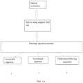
- the wind airflow includes at least two-stage separation, including one or more permutations and combinations of accelerated separation, gravity removal separation and fluidized billowing separation.
- the accelerated separation includes the following steps: the internal strong magnetic field unit and the accelerated separation unit are used to realize the accelerated separation under the action of the internal strong magnetic field,
- the acceleration of material depends on the airflow ejected by the accelerator in the accelerated separation unit acting on the material particles to accelerate them step by step or single stage, resulting in rapid movement;
- the particle speed should be accelerated or adjusted to more than 0.2m/s.
- the gravitational separation includes the following processes: when the material still carrying impurities passes through it, the impurities will be taken away by the high-speed airflow here; At the same time, the strong magnetic unit on flank mechanism provides a strong magnetic field here, so it is also the main place to remove electromagnetic force.
- Gravity removal separation unit includes conductive and grounded flank mechanism and a strong magnetic field unit arranged on the flank mechanism. Under the action of the built-in strong magnetic field unit and conductive and grounded flank mechanism, the attraction and static electricity on material are eliminated. When the flying material collides with the flank mechanism, the residual impurities attached to the surface of the material will be separated from the material under the collision friction, and this part of the separated impurities will be taken away by the high-speed airflow and flow to the gas outlet.
- fluidized billowing separation includes the following processes: fluidization unit is used to fluidize the material, the attraction between granular materials and impurities attached to its surface is eliminated again, and pure gas is used to fully wash, separate and purify the material, so as to enhance the separation effect of the material and impurities.
- the fluidized billowing separation is realized by adjusting the size of the fluidization plate hole in the fluidization unit from 0.5mm to 5mm and the opening degree of the wind valve.
- spectrum generator microwave generator or plasma generator can be used for auxiliary gravitational elimination and sterilization of materials, cleaner internals, gases and impurities.
- the wavelength of spectrum emitted by spectrum generator is 250 ⁇ 280nm, and its illumination intensity should be controlled above 18 ⁇ W/cm2.
- spectrum generator can be used for auxiliary gravitational elimination and sterilization of materials, cleaner internals, gases and impurities.
- the wavelength of spectrum emitted by spectrum generator is 250 ⁇ 280nm, and its illumination intensity should be controlled above 18 ⁇ W/cm2.
- the application of method of accelerating material cleaning with strong magnet particles is characterized in that it is applied to material cleaner to obtain a strong magnet particle acceleration material cleaner.
- the application of method of accelerating material cleaning with strong magnet particles is characterized in that it is applied to a material purification system to obtain a strong magnet particle accelerating material purification system.
- each reference numeral is: 1: material inlet, 2: material inlet distribution unit, 3: flank mechanism, 4: fluidized billowing separation unit, 5: outrigger, 6: case, 7: accelerated separation unit, 8: internal strong magnetic field unit, 9: spectrum generator, 10: material exit, 11: gas outlet, 12: gas inlet, 13: clear window, 14: feed bin, 15: valve, 16: cleaner, 17: receiving device, 18: silencer, 19: filter, 20: fan, 21: separator, 22: precision filter, 23: material level controller.
- the Lorentz force will be generated when the electric charge moves in the magnetic field, and the faster the electric charge moves, the stronger the Lorentz force will be.
- the polarity of the electric charge carried by the material and the impurities is opposite, so the Lorentz force exerted by the material and the impurities is also opposite, and the distance between the material and the impurities will increase, thus weakening and removing the carried electromagnetic force, and at the same time, pulling force will be generated between the particles and the attached impurities.
- the strong magnetic field generated by strong permanent magnet (NdFeB, samarium cobalt, etc.) or the strong magnetic field generated by electromagnetic coil is used to eliminate the attraction between particles and impurities.
- strong permanent magnet NaFeB, samarium cobalt, etc.
- Magnetic field intensity is higher than 0.06 tesla (600 gauss) at 2mm from the magnet.
- the invention has a wide range of applications, and the material selection of case and internal parts is determined according to the characteristics of materials.
- stainless steel can be used as case and internal parts; for some mineral products, ordinary carbon steel can be used as case or internal parts; for the requirements of grain, feed and other industries, suitable metal materials and even FRP can be used as case and internal parts.
- the processing technology can also adopt bonding, riveting, linking and other ways.
- a method of accelerating material cleaning with strong magnet particles Entering from the material Inlet, wind airflow cooperate with the accelerator to accelerate the material, which makes the material particles move at a certain speed.
- the position point and speed of the material when it reaches the highest speed can be controlled, that is, the material speed is controlled by the wind speed, and the position point when the material reaches the highest speed is the speed at the end of the accelerator.
- the internal strong magnetic field can be used to eliminate the attractive forces such as electromagnetic force, van der Waals force and liquid bridge between the material and the impurities attached to the material surface. At the same time, it can be matched with the wind airflow and the friction collision with the internal parts to weaken the attractive forces such as van der Waals force and liquid bridge between the material particles and the impurities attached to it, so as to improve the cleanliness of the material.
- Strong magnetic field is produced by strong permanent magnet materials or electromagnetic coils which are distributed in one or more places.
- the magnetic induction intensity which is distributed near the area where the material flows at a high speed and located at the installation point of strong magnet 2mm is higher than 0.06 tesla (600 gauss) as far as possible.
- the strong magnetic field unit is integrated, attached and matched with other units in physical space, and together with moving particles and impurities, electrostatic and remanence existing between particles and impurities attached to their surfaces can generate electromagnetic force in opposite directions, so that the two units can generate gaps or separate, and the attached impurities can be transformed into dispersed impurities, thus improving the cleaning effect.
- the first method of accelerating material cleaning with strong magnet particles is listed, as a basic example, as shown in FIG. 2A , which specifically includes the following steps: Step 1, the first-stage accelerated separation includes the following steps: the internal strong magnetic field unit and the accelerated separation unit are used to realize the accelerated separation under the action of the internal strong magnetic field, The acceleration of material depends on the airflow ejected by the accelerator in the accelerated separation unit acting on the material particles to accelerate them step by step or single stage, resulting in rapid movement;
- the particle speed should be accelerated or adjusted to more than 0.2m/s.
- the unit integrates multiple functions, and it not only provides a wind distribution port, but also makes the air flow jetted by the accelerator above the first-stage accelerated separation unit act on the material, accelerating the movement speed of the material particles step by step or single-stage, at the same time, making the dispersed impurities separate from the material flow.
- the sliding plate cooperates with the accelerator to increase the collision effect during the operation of the material, so as to eliminate Van der Waals and liquid bridge between the material particles and their attached impurities. The conductivity and sufficient grounding of the sliding plate will discharge the static electricity of the material.
- two-stage gravitational separation is the main step of separating impurities from material, which includes the following processes: when the material which is separated from the first-stage acceleration and still carries impurities passes through it, the impurities will be taken away by the high-speed airflow here, the strong magnetic unit on flank mechanism provides a strong magnetic field here, so it is also the main place to remove electromagnetic force. Or a region formed by combining a strong magnetic unit on a first-stage accelerated separation unit, When the flying material collides with the flank mechanism, the residual impurities attached to the surface of the material will be separated from the material under the collision friction, and this part of the separated impurities will be taken away by the high-speed airflow and flow to the gas outlet.
- Gravity removal separation unit includes conductive and grounded flank mechanism and a strong magnetic field unit arranged on the flank mechanism. Under the action of the built-in strong magnetic field unit and conductive and grounded flank mechanism, the attraction and static electricity on material are eliminated. When the flying material collides with the flank mechanism, the residual impurities attached to the surface of the material will be separated from the material under the collision friction, and this part of the separated impurities will be taken away by the high-speed airflow and flow to the gas outlet.
- the repulsive force of strong magnet magnetic field is the largest when the material speed is the largest, and the repulsive electromagnetic force between particles and impurities blows away by wind.
- Gravitational separation the wing plate located between the upper and lower cavities of the equipment and its vicinity, is the main step of separating impurities from materials.
- This stage is the main battlefield for eliminating the gravitational force between materials and the impurities attached to its surface, and the scattered impurities left over from the previous stage are purified by strong air flow again, and the impurities of this stage that have eliminated the gravitational force are simultaneously purified by strong air flow.
- Step 3 three-stage fluidize billowing separation: fluidize billowing separation includes that following process: fluidizing and billowing the material by using the fluidization unit, once again eliminating the attraction between the granular material and the impurities attached to its surface, fully washing, separating and purifying the material with pure gas, and enhancing the separation effect of the material and impurities.
- the fluidized billowing separation effect can be achieved by adjusting the size of the fluidization plate hole in the fluidization unit to 0.5mm-5mm and the opening of the wind valve. After the material is removed and separated by secondary gravity, the clean air blown out from the air outlet under the fluidization plate blows it up, resulting in a "billowing" effect. The clean air fully contacts and acts with the material, causing the material to turn over and collide, thus realizing the full washing of the material.
- the upper part of the component receives the material from gravity removal separation unit, and the lower part is connected with the clean material outlet;
- One function of this part of fluidization plate is to take away the residual impurities on the surface of the material, and the other function is to create gas supply conditions for the formation of the upper gravity removal separation unit.
- the impurity content of the material can reach 15ppm after being treated by cleaner with optimized parameters.
- the order and number of separation unit can be adjusted, including one or more permutation combinations of accelerated separation, gravitational separation and fluidized billowing separation.
- the first-stage fluidized billowing separation For example, the first-stage fluidized billowing separation, the second-stage accelerated separation and the first-stage gravity removal separation unit.
- adjust the number of separation unit such as one-stage accelerated separation, two-stage accelerated separation, three-stage gravity separation and four-stage fluidized billowing separation.
- one-stage accelerated separation two-stage gravity separation, three-stage gravity separation and four-stage fluidized billowing separation. And so on and so forth.
- first-stage accelerated separation such as first-stage accelerated separation, second-stage accelerated separation and third-stage accelerated separation; For example, one-stage accelerated separation, two-stage gravity removal separation unit, and three-stage gravity removal separation unit; And so on and so forth.
- spectrum generator can be used for auxiliary gravitational elimination and sterilization of materials, cleaner internals, gases and impurities.
- the wavelength of spectrum emitted by spectrum generator is 250 ⁇ 280nm, and its illumination intensity should be controlled above 18 ⁇ W/cm2.
- the application of method of accelerating material cleaning with strong magnet particles is applied to material cleaner to obtain a strong magnet particle acceleration material cleaner.
- the material enters from the material inlet, and the material outlet can be directly connected to the material receiving facilities or equipment, such as: the material packaging machine or bulk tank car, the gas inlet is connected to the air inlet pipeline, and the gas outlet is connected to the gas outlet pipeline;
- the material inlet enters the equipment, passes through the inlet distribution unit, each separation unit and strong magnetic field unit, and then is discharged from the material exit.
- the wind force configured in the process acts on the separation units at all levels, and the separated impurities are carried by the gas from the gas outlet and separated from the cleaner, and then enter the supporting gas purification facilities for separation and collection.
- the above-mentioned separation unit includes one or more permutations of accelerated separation, gravitational separation and fluidized billowing separation.
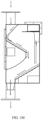
- the first strong magnet particle acceleration material cleaner is listed as a basic example, as shown in FIGS. 1B to 1M .
- the material moves and flows in a variety of ways in the cleaner according to the set way, and the impurities in the material are separated and separated from the material by various wind forces, thus achieving the function of purifying the material.
- the treatment capacity is from 100kg/h to 100T/h, and the separation accuracy can reach 15ppm.
- the internal structure of the cleaner takes rectangular shape and internal two-sided blanking as an example, and includes two groups of blanking components, each group of blanking components includes a Material inlet distribution unit, an accelerated separation unit, The functions of two-stage gravity removal separation unit, three-stage fluidized bed billowing separation unit, strong magnetic field unit, spectrum generator, etc., as mentioned above, will not be described in detail. Their structures are simple, and they are briefly described in detail as shown in the FIG.. According to the different properties of materials to be treated, different case and internal materials can be used, such as stainless steel (304,304L, 316,316L), common carbon steel, aluminum, plastic resin and glass fiber reinforced plastic.
- a strong magnetic field unit is arranged, and by utilizing a strong magnetic field generated by a strong permanent magnet (neodymium iron boron, samarium cobalt), the accelerated material particles can eliminate the electromagnetic force attraction between the impurities and the materials, so as to achieve the purpose of eliminating the electromagnetic force between the impurities and the materials.
- a strong permanent magnet neodymium iron boron, samarium cobalt
- the permanent magnets of the strong magnet unit are distributed near the area where the material flows at a high speed, and the magnetic field intensity at 2mm from the installation point should be higher than 0.06 tesla (600 gauss).
- this product can also use electromagnetic coil to generate strong magnetic field, so as to eliminate the electromagnetic force between the material and its adsorbed impurities, and connect DC, AC and various harmonic power supplies to the electromagnetic coil.
- the non-DC power supply will generate large electromagnetic radiation, so the radiation intensity should be controlled within the local relevant standards.
- the strong magnet can be set at many points in the area where the material flows, such as the material inlet of the equipment, the material exit of the equipment, the first-class accelerated separation unit, Secondary gravity 5removal separation unit and tertiary fluidized billowing separation unit.
- the Material inlet distribution unit of the invention is connected with the material inlet, and is provided with an adjustable adjusting plate, and a gap is arranged between the adjusting plate and the upper surface of the first-stage acceleration unit, so that the material can flow out uniformly;
- the adjusting plate is manually or automatically adjusted by the adjusting mechanism, aiming at uniformly and controllably distributing the materials from the material inlet to the upper surface of the first-level accelerated separation unit;
- the materials entering the equipment can be uniformly distributed on the sliding plate of the first-level accelerated separation unit, and if the materials are not uniform, the separation effect will be reduced.
- Different materials may have different fluidity, and materials with good fluidity can flow out evenly from the gap between the regulating plate of the inlet distribution unit and the upper surface of the first-stage acceleration unit;
- the material with poor fluidity may fill the gap between the inlet distribution unit and the lower acceleration unit after entering the equipment from the inlet, so that the material cannot flow out of the gap evenly. Therefore, it is necessary to regulate the regulating plate and its mechanism, so that the material can flow out evenly from the gap between the inlet distribution unit and the upper surface of the first acceleration unit, thus laying the foundation for effective separation of materials and impurities.
- the area occupied by the first-stage accelerated separation unit just provides an air inlet for the upper space, and this part of air is used to power the accelerated movement of the material.
- the upper surface of the first-level accelerated separation unit is provided with an accelerator and a sliding plate.
- the material with a certain downward speed passes through the surface of the sliding plate, it will collide, which can partially clean up the impurities adhered to the surface of the material;
- a certain number of pores are opened (the shape of pores can be rectangle, square, circle, ellipse, triangle, diamond, and other special shapes). The airflow blown out from these pores gives the material a driving force in the process of sliding down, which makes the material run down at a faster speed and provides enough momentum for the next impact.
- the movement speed is in the range of 0.2 m/s to 50 m/s, which can obtain ideal impact friction effect. Outside this speed range, if it is too low, the separation effect is not ideal, and the residual impurities may not be separated. If it is too high, the material may be broken.
- the arc-shaped back cover As the arc-shaped back cover is adopted, the upward flow of air in the bottom space is smoother, and at the same time, the arc-shaped back cover makes the space at the lower part of the equipment larger, creating favorable conditions for gravity removal separation unit and third-stage fluidized billowing separation unit.
- the acceleration function of the first-stage accelerated separation unit is realized by the multi-stage accelerator and multi-stage sliding plate (or single stage).
- the angle between the sliding plate and the vertical direction should be less than 80 degrees, while the angle between the accelerator and the horizontal direction is 10-170 degrees (or -80-80 degrees with the vertical direction).
- the secondary gravity removal separation unit is a three-dimensional area between the primary accelerated separation unit and the flank mechanism, and the bottleneck between the upper and lower cavities of the equipment is also at this level.
- the airflow speed through the bottleneck rapidly increases (not enough to take away the material).
- the gas in the lower space flows to the secondary gravity removal unit as if it were pumped by a powerful pump, while the gas in the upper space flows to the gas outlet of the equipment as if it were driven by a powerful force with impurities.
- Secondary gravity removal separation unit is the main area where impurities are separated from materials.
- the impurities will be taken away by the high-speed airflow here.
- the strong magnetic unit on the first-stage accelerated separation unit and the strong magnetic unit on the flank mechanism provide a strong magnetic field here, so this is also the main place for removing electromagnetic force.
- the flying material collides with the flank mechanism the residual impurities attached to the surface of the material will be separated from the material under the collision friction, and this part of the separated impurities will be taken away by the high-speed airflow and flow to the gas outlet.
- the three-stage fluidized billowing separation unit of the invention includes a fluidization plate and a three-dimensional space of the upper part thereof, wherein the fluidization plate is provided with a dry air outlet, and the surface of the fluidization plate is mirror-polished, and at the same time, the surface of the fluidization plate is provided with a plurality of small holes, and a part of the gas coming in from the gas inlet enters the lower space through the small holes, and one function of the fluidization plate is to take away the residual impurities on the surface of the material,
- the fluidization plate is provided with a conductive layer and sufficiently grounded to discharge the static electricity of the material again;
- the three-stage fluidized billowing separation unit refers to the three-dimensional space of the fluidization plate and its upper part.
- the material is subjected to the third gas washing separation by the mechanism of fully billowing gas washing, friction and collision, magnetic field eliminating the electromagnetic force of moving material, etc.
- the adhesive impurities are eliminated by electromagnetic force, Van der Waals force, liquid bridge and other gravitational forces, and once again, the adhesive impurities are transformed into dispersed impurities, and the dispersed impurities remaining after the previous unit is not separated are separated.
- the static electricity of the material is discharged again by means of the conductivity and sufficient grounding of the fluidization plate. Make the cleanliness of the material go up to a higher level, and the impurity content of the material can be reduced to 15ppm after the cleaner treatment with optimized parameters.
- a three-stage fluidized billowing separation unit which blows the material from the air outlet under the fluidization plate when it comes out of the two-stage gravity removal separation unit and enters the unit.
- the upper part of the component receives the material from the gravity removal separation unit, and the lower part is connected with a clean outlet,
- the surface of this component is polished by mirror, in order to avoid the dust generated by friction when the material flows over it.
- the surface is also provided with a number of small holes, through which part of the gas coming in from the gas inlet enters the lower space.
- One function is to take away the residual impurities on the surface of the material, and the other is to create conditions for the formation of the upper gravity removal separation unit.
- a single point or multiple points are internally provided with illumination equipment, and the illumination equipment emits light with a wavelength of 240-280 nm.
- the light with this wavelength can kill and destroy the molecular structure of DNA (deoxyribonucleic acid) or RNA (ribonucleic acid) in bacteria and viruses, so as to achieve the effect of sterilization and disinfection, and at the same time, it plays an auxiliary role in eliminating the attraction between material and impurities attached to it.
- cleaner and the shape of sliding plate, accelerator, flank mechanism and fluidization plate are not limited to square, but also can be round, semicircular, annular, rectangular, triangular, rhombic, oval and other special shapes.
- One of the important functions of distribution unit, sliding plate, flank mechanism and fluidization plate is to lead out static electricity of material and impurities.
- the contact resistance between these facilities and cleaner grounding point should be less than 10 ohms.
- an ion wind generator can also be installed to enhance the electrostatic removal effect.
- Accelerator and sliding plate can be integrated or independent.
- Cleaner can operate in either open loop mode or closed loop mode. See the notes for details.
- the internal structure of the cleaner can also adopt a one-sided structure for the small-flow (flow less than 20 tons/hour) cleaner, that is, the Material inlet distribution unit, the first-stage accelerated separation unit, the second-stage gravity removal separation unit and the third-stage fluidized bed billowing unit can also adopt a one-sided blanking form. If the space is not limited, even if the flow rate exceeds 20 tons/hour, one-sided blanking can be adopted.
- the first-class accelerated separation unit, the second-class gravity removal separation unit and the third-class fluidized billowing separation unit can be added. That is, there may be multiple primary accelerated separation unit, multiple secondary gravity removal separation unit, multiple tertiary fluidized billowing separation unit, and expansion of other units.
- the cleaner with small flow can also adopt one-sided structure, that is, the Material inlet distribution unit, the first-stage accelerated separation unit, the second-stage gravity removal separation unit and the third-stage fluidized billowing separation unit can also adopt one-sided blanking. If the space is not limited, even if the flow rate exceeds 20 tons/hour, one-sided blanking can be adopted.
- the first-class accelerated separation unit, the second-class gravity removal separation unit and the third-class fluidized billowing separation unit can be added. That is, there may be multiple primary accelerated separation unit, multiple secondary gravity removal separation unit, multiple tertiary fluidized billowing separation unit, and expansion of other units.
- Accelerator and sliding plate can be integrated or independent.
- the application of method of accelerating material cleaning with strong magnet particles is characterized in that it is applied to a material purification system to obtain a strong magnet particle accelerating material purification system.
- the composition of strong magnet particle accelerated material purification system can be open-loop or closed-loop.
- Open loop the wind with impurities coming out of the gas outlet of the strong magnet particle acceleration material cleaner is directly discharged after being treated and is not reused; Closed loop, otherwise, the treated wind will be sent to the gas inlet of the strong magnet particle acceleration material cleaner for repeated use.
- Open loop high energy consumption, many equipments, no dangerous gas accumulation and high safety; Closed loop, less energy consumption, less equipment and poor safety due to explosive gas accumulation.
- the cleaner of the second embodiment can form a material purification system with valve such as fan, filter, cyclone, rotary valve or slide valve, silencer, isolation hopper (optional), etc. It means that the gas inlet and gas outlet of the material purification system are both open. Generally, the system is equipped with two fans, which are located in the gas outlet and gas inlet respectively, and their outlets and inlets are directly connected with the gas outside the system.
- valve such as fan, filter, cyclone, rotary valve or slide valve, silencer, isolation hopper (optional), etc. It means that the gas inlet and gas outlet of the material purification system are both open.
- the system is equipped with two fans, which are located in the gas outlet and gas inlet respectively, and their outlets and inlets are directly connected with the gas outside the system.
- the cleaner of the second embodiment can form a material purification system with valve such as fan, filter, cyclone, rotary valve or slide valve, silencer, isolation hopper (optional), etc. It means that the process of the purified gas system of this material is closed, and a fan provides gas power, with cleaner as the core, and air purification equipment on both sides of it as the auxiliary. The purified gas is recycled repeatedly, and each cycle must be purified by purification facilities.
- valve such as fan, filter, cyclone, rotary valve or slide valve, silencer, isolation hopper (optional), etc.
Landscapes
- Health & Medical Sciences (AREA)
- Epidemiology (AREA)
- Life Sciences & Earth Sciences (AREA)
- Animal Behavior & Ethology (AREA)
- General Health & Medical Sciences (AREA)
- Public Health (AREA)
- Veterinary Medicine (AREA)
- Combined Means For Separation Of Solids (AREA)
- Physical Or Chemical Processes And Apparatus (AREA)
- Cleaning In General (AREA)
Claims (17)
- Verfahren zur Beschleunigungsteilchenmaterialreinigung mit einem Starkmagnet, umfassend:ein Material tritt durch einen Materialeinlass (1) ein; eine Beschleunigung des Materials wird durch einen Windluftstrom mit einem Beschleuniger erreicht, wobei sich Materialteilchen mit einer vorbestimmten Geschwindigkeit bewegen und ein Ortspunkt und eine Geschwindigkeit, wenn das Material eine Höchstgeschwindigkeit erreicht, ausgelegt sind, um gesteuert zu werden, wobei eine Materialgeschwindigkeit durch eine Windgeschwindigkeit geregelt wird und der Ortspunkt, wenn das Material die Höchstgeschwindigkeit erreicht, eine Geschwindigkeit eines Endbereichs des Beschleunigers ist;eine Starkmagnetfeldeinheit (8) ist an einem Punkt zwischen der Stelle, an der das Material aus dem Materialeinlass (1) eintritt und aus einem Materialauslass (10) austritt, installiert, wobei die Starkmagnetfeldeinheit (8) vorzugsweise angrenzend an den Punkt installiert ist, an dem das Material die Höchstgeschwindigkeit erreicht, wobei die interne Starkmagnetfeldeinheit (8) ausgelegt ist, um ein internes Starkmagnetfeld zu erzeugen,wobei das interne Starkmagnetfeld eine Schwerkraft beseitigt, umfassend eine elektromagnetische Kraft, eine Van-der-Waals-Kraft und eine Flüssigkeitsbrücke zwischen dem Material und den an einer Materialoberfläche haftenden Verunreinigungen, die Van-der-Waals-Kraft und die Flüssigkeitsbrücke zwischen den Materialteilchen und den an der Materialteilchen haftenden Verunreinigungen gleichzeitig, kombiniert mit dem Windluftstrom und einer Reibungskollision mit internen Teilen, abgeschwächt werden, was eine Sauberkeit des Materials verbessert, dadurch gekennzeichnet, dass die durch die Magnetfeldeinheit erzeugte Magnetfeldstärke 2 mm vom Magnet größer als 0,06 Tesla (600 Gauß) ist.
- Verfahren nach Anspruch 1, wobei das Starkmagnetfeld durch Stark-Permanentmagnetmaterialien oder elektromagnetische Spulen erzeugt wird, wobei die Stark-Permanentmagnetmaterialien oder die elektromagnetischen Spulen an einem Punkt verteilt sind und eine magnetische Flussdichte vorzugsweise möglichst größer als 0,06 Tesla (600 Gauß) ist,
wobei die magnetische Flussdichte angrenzend an einen Bereich mit hoher Materialströmungsgeschwindigkeit und befindlich an einem Installationspunkt 2 mm von einem Starkmagnet verteilt ist, die Starkmagnetfeldeinheit (8) in einem physischen Raum mit andere Einheiten integriert, an diesen angebracht und passend zu diesen ausgebildet ist und zusammen mit den sich bewegenden Teilchen und den Verunreinigen, einer Elektrostatik und einer Remanenz, bestehend zwischen den Teilchen und den an Oberflächen der Teilchen haftenden Verunreinigungen, ausgelegt ist, um eine elektromagnetische Kraft in entgegengesetzte Richtungen zu erzeugen, wobei die Teilchen und die Verunreinigungen ausgelegt sind, um Lücken zu erzeugen oder sich trennen, und die haftenden Verunreinigungen ausgelegt sind, um in dispergierte Verunreinigungen umgewandelt zu werden, um eine Reinigungswirkung zu verbessern, das Volumen, eine Größe und Form des Starkmagnets vorzugsweise auf Arbeitsbedingungen abgestimmt sind, wobei der Starkmagnet die Starkmagnetfeldeinheit (8) bildet, eine Erzeugung des Starkmagnetfelds der Starkmagnetfeldeinheit (8) auch ausgelegt ist, um durch Anschließen von Gleich-, Wechsel- und verschiedenen Oberschwingungsstromversorgungen an die elektromagnetische Spule herbeigeführt zu werden, wobei eine elektromagnetische Strahlungsintensität, abgesehen davon, wenn Gleichstrom genutzt wird, vorzugsweise kleiner als ein relevanter Standard ist. - Verfahren nach Anspruch 1, wobei der Windluftstrom mindestens eine zweistufige Trennung umfasst, umfassend mindestens eine Permutation und Kombination aus einer beschleunigten Trennung, einer Schwerkrafttrennung und einer fluidisierten Aufblähungstrennung.
- Verfahren nach Anspruch 3, wobei die beschleunigte Trennung die folgenden Schritte umfasst: die interne Starkmagnetfeldeinheit (8) und eine Einheit für beschleunigte Trennung (7) sind ausgelegt, um die beschleunigte Trennung zu realisieren, und die Beschleunigung des Materials hängt von einem Luftstrom ab, der vom Beschleuniger in der Einheit für beschleunigte Trennung (7) gesprüht wird, um auf die Materialteilchen einzuwirken, um die Materialteilchen stufenweise oder einstufig zu beschleunigen, was zu einer schnellen Bewegung führt;
an einem Ende der Einheit für beschleunigte Trennung (7) wird eine Teilchengeschwindigkeit vorzugsweise beschleunigt oder auf mehr als 0,2 m/s angepasst; wenn die Teilchengeschwindigkeit zunimmt, wird eine Reinigungswirkung verbessert, aber eine übermäßige Geschwindigkeit beschädigt die Teilchen, wobei die Teilchengeschwindigkeit vorzugsweise auf eine Obergrenze eingestellt wird, wobei die Obergrenze im Allgemeinen geringer als 50m/s ist und von einer Art eines bestimmten Materials abhängt. - Verfahren nach Anspruch 3, wobei die Schwerkrafttrennung die folgenden Prozesse umfasst: Wenn das noch Verunreinigungen tragende Material die mindestens zweistufige Trennung durchläuft, umfassend die mindestens eine Permutation und Kombination der beschleunigten Trennung, der Schwerkrafttrennung und der fluidisierten Aufblähungstrennung, werden die Verunreinigungen durch den Hochgeschwindigkeitsluftstrom entfernt; gleichzeitig stellt die Starkmagnetfeldeinheit (8) hier auf einem Flankenmechanismus (3) ein Starkmagnetfeld bereit, sodass die Starkmagnetfeldeinheit (8) ferner ein Hauptort ist, um die elektromagnetische Kraft zu entfernen;
eine Schwerkraftentfernungstrenneinheit umfasst den leitfähigen und geerdeten Flankenmechanismus (3) und die Starkmagnetfeldeinheit (8), angeordnet auf dem Flankenmechanismus (3); unter einer Wirkung der internen Starkmagnetfeldeinheit (8) und des leitfähigen und geerdeten Flankenmechanismus (3) werden eine Anziehung und eine statische Elektrizität auf dem Material beseitigt; wenn das fliegende Material auf den Flankenmechanismus (3) trifft und diesen reibt, werden Restverunreinigungen, die an der Materialoberfläche haften, unter einer Kollisionsreibung vom Material getrennt, und der Teil von getrennten Verunreinigungen wird durch den Hochgeschwindigkeitsluftstrom entfernt und strömt zu einem Gasauslass (11). - Verfahren nach Anspruch 3, wobei die fluidisierte Aufblähungstrennung die folgenden Prozesse umfasst: Eine Fluidisierungseinheit ist ausgelegt, um das Material zu fluidisieren; eine Anziehung zwischen körnigen Materialien und Verunreinigungen, die an einer Oberfläche der körnigen Materialien haften, wird erneut beseitigt, und ein reines Gas ist ausgelegt, um das Material völlig zu waschen, zu trennen und zu reinigen, um eine Trennwirkung des Materials und der Verunreinigungen zu optimieren.
- Verfahren nach Anspruch 6, wobei die fluidisierte Aufblähungstrennung durch Anpassen einer Größe eines Fluidisierungsplattenlochs in der Fluidisierungseinheit von 0,5 mm auf 5 mm und eine Öffnung eines Luftventils realisiert wird.
- Verfahren nach Anspruch 1, wobei sich einige Bakterien oder Schimmel bilden können, wenn das Material nass ist oder Feuchtigkeit aufnimmt oder anderen Gründen ausgesetzt ist, was zu einer Verschlechterung und einem Versagen des Materials führt, wobei mindestens ein Element, ausgewählt aus der Gruppe, bestehend aus einem Spektrum-Generator (9), einem Mikrowellengenerator und einem Plasmagenerator, für eine zusätzliche Schwerkraftbeseitigung und Sterilisation des Materials, der Reinigerinnenbereiche, Gase und der Verunreinigungen ausgelegt ist, eine Wellenlänge des vom Spektrum-Generator (9) abgestrahlten Lichts 250 bis 280 nm beträgt und eine Beleuchtungsstärke des Spektrum-Generators (9) vorzugsweise über 18 µW/cm2 gesteuert ist.
- Vorrichtung, die ein Verfahren zur Beschleunigungsteilchenmateriallreinigung mit einem Starkmagnet verwendet, wobei die Vorrichtung durch Anwendung des Verfahrens auf einen Materialreiniger, um die Vorrichtung zu erhalten, ein Starkmagnet-Teilchenbeschleunigungsmaterialreiniger ist, wobei der Starkmagnet-Teilchenbeschleunigungsmaterialreiniger ein Gehäuse (6) umfasst und das Gehäuse (6) Folgendes umfasst:eine Austastungstrenneinheit, wobei die Austastungstrenneinheit mit einer Materialbeschleunigungskomponente ausgestattet ist und einen Beschleuniger, einen Gaseinlass (12) und einen Gasauslass (11) umfasst und die Austastungstrenneinheit mindestens zwei Trennstufen umfasst, umfassend mindestens eine Permutationskombination aus einer Einheit für beschleunigte Trennung (7), einer Schwerkraftentfernungstrenneinheit und einer Einheit für fluidisierte Aufblähungstrennung (4);eine Starkmagnetfeldeinheit (8), die zwischen der Stelle, an der ein Material aus dem Materialeinlass (1) eintritt und aus einem Materialauslass (10) austritt, angeordnet ist,wobei die Vorrichtung so ausgelegt ist, dass das Material vom Materialeinlass (1) eintritt und ein Windluftstrom mit dem Beschleuniger zusammenwirkt, um eine Beschleunigung des Materials herbeizuführen, wobei sich die Materialteilchen bei einer vorbestimmten Geschwindigkeit bewegen und ein Positionspunkt, wenn das Material eine höchste Geschwindigkeit erreicht, eine Geschwindigkeit an einem Ende des Beschleunigers ist,wobei die interne Starkmagnetfeldeinheit (8) ausgelegt ist, um ein internes Starkmagnetfeld zu erzeugen, wobei das interne Starkmagnetfeld ausgelegt ist, um Anziehungskräfte, umfassend eine elektromagnetische Kraft, eine Van-der-Waals-Kraft und eine Flüssigkeitsbrücke zwischen dem Material und den an einer Oberfläche des Materials haftenden Verunreinigungen, zu beseitigen, und das interne Starkmagnetfeld gleichzeitig ausgelegt ist, um mit dem Windluftstrom zusammenzuwirken, die Van-der-Waals-Kraft zwischen den Materialteilchen und den an den Materialteilchen haftenden Verunreinigungen durch eine Reibung und durch eine Kollision mit internen Teilen abzuschwächen und eine Sauberkeit des Materials zu verbessern, dadurch gekennzeichnet, dass die von der Starkmagnetfeldeinheit (8) erzeugte Magnetfeldstärke 2 mm vom Magnet größer ist als 0,06 Tesla (600 Gauß).
- Vorrichtung nach Anspruch 9, wobei die Starkmagnetfeldeinheit (8) einen Stark-Permanentmagnet oder eine elektromagnetische Spule, verteilt an einem Punkt oder mehreren Orten, umfasst und in einem Bereich befindlich ist, in dem das Material strömt, wobei der Bereich den Materialeinlass (1), den Materialauslass (10) und die Einheit für beschleunigte Trennung (7) umfasst, die Permanentmagnete auf der Schwerkraftentfernungstrenneinheit und der Einheit für fluidisierte Aufblähungstrennung (4) vorzugsweise so angrenzend wie möglich an den Bereich verteilt sind, in dem das Material bei hoher Geschwindigkeit strömt, und eine magnetische Flussdichte 2 mm von einem Installationspunkt eines Starkmagnets vorzugsweise größer als 0,06 Tesla (600 Gauß) ist,wobei die Starkmagnetfeldeinheit (8) angrenzend an den Positionspunkt angeordnet ist, wenn das Material die höchste Geschwindigkeit erreicht,wobei ein Volumen, eine Größe und eine Form des Starkmagnets vorzugsweise auf Arbeitsbedingungen abgestimmt sind, wobei der Starkmagnet die Starkmagnetfeldeinheit (8) bildet, eine Erzeugung des Starkmagnetfelds der Starkmagnetfeldeinheit (8) ausgelegt ist, um durch Anschließen von Gleich-, Wechsel- und verschiedenen Oberschwingungsstromversorgungen an die elektromagnetische Spule herbeigeführt zu werden, wobei eine elektromagnetische Strahlungsintensität, abgesehen davon, wenn Gleichstrom genutzt wird, vorzugsweise kleiner als relevante Standards ist.
- Vorrichtung nach Anspruch 9 oder 10, wobei eine einseitige Austastungstrenneinheit, eine zweiseitige Austastungstrenneinheit oder mehrere Gruppen von Austastungstrenneinheiten im Gehäuse (6) angeordnet sind, wobei bei Arbeitsbedingungen mit hohen Anforderungen an die Sauberkeit eine Kombination aus mehreren Einheiten für beschleunigte Trennung (7), mehreren Schwerkraftentfernungstrenneinheiten, mehreren Einheiten für fluidisierte Aufblähungstrennung (4) und eine Erweiterung anderer Einheiten in einer einseitigen Austastungstrenneinheit eingesetzt werden.
- Vorrichtung nach Anspruch 9, wobei die Einheit für beschleunigte Trennung (7) mit 1-stufigen oder mehrstufigen Beschleunigern, 1-stufigen oder mehrstufigen Gleitplatten und Windverteilungsanschlüssen versehen ist, ein eingeschlossener Winkel zwischen den 1-stufigen oder mehrstufigen Gleitplatten und einer vertikalen Richtung kleiner als 80 Grad ist und ein eingeschlossener Winkel zwischen dem 1-stufigen oder mehrstufigen Beschleuniger und einer horizontalen Richtung 10 bis 170 Grad beträgt oder ein eingeschlossener Winkel zwischen dem 1-stufigen oder mehrstufigen Beschleuniger und der vertikalen Richtung -80 bis 80 Grad beträgt, jeder 1-stufige oder mehrstufige Beschleuniger mit einer vorbestimmten Anzahl an Poren versehen ist, wobei die vorbestimmte Anzahl an Poren mit dem Windverteilungsanschluss abgestimmt ist, um dafür zu sorgen, dass ein aus dem 1-stufigen oder mehrstufigen Beschleuniger ausgeworfener Luftstrom auf das Material wirkt, eine Bewegungsgeschwindigkeit der Materialteilchen beschleunigt und gleichzeitig dafür sorgt, dass sich die dispergierten Verunreinigungen vom Materialstrom trennen, wobei der 1-stufige oder mehrstufige Beschleuniger und die 1-stufige oder mehrstufige Gleitplatte ausgelegt sind, um miteinander integriert oder unabhängig voneinander zu sein.
- Vorrichtung nach Anspruch 9, wobei die Schwerkraftentfernungstrenneinheit einen Flankenmechanismus (3) umfasst, der Flankenmechanismus (3) Seitenklappen, eine manuelle Einstellausrüstung und einen Windverteilungsmechanismus umfasst.
- Vorrichtung nach Anspruch 9, wobei die Einheit für fluidisierte Aufblähungstrennung (4) eine Fluidisierungsplatte und einen dreidimensionalen Raum umfasst, wobei ein oberer Teil der Fluidisierungsplatte zum dreidimensionalen Raum gehört, die Fluidisierungsplatte mit einem Trockenluftauslass versehen, wobei ein Teil eines aus dem Gaseinlass (12) einströmenden Gases durch den Trockenluftauslass in einen unteren Raum eintritt, eine erste Funktion darin besteht, dafür zu sorgen, dass sich das Material aufbläht, umdreht, kollidiert und Restverunreinigungen wegspült, und eine zweite Funktion darin besteht, ein erforderliches Gas für eine obere Stufe bereitzustellen, wobei die Fluidisierungsplatte mit einer leitfähigen Schicht versehen und ausreichend geerdet ist, um eine statische Elektrizität des Materials wieder zu entladen und eine Größe von Fluidisierungsplattenlöchern in der Einheit für fluidisierte Aufblähungstrennung (4) 0,5 mm bis 5 mm beträgt.
- Vorrichtung nach Anspruch 9, wobei mindestens eine Gruppe eines Spektrum-Generators (9), der ausgelegt ist, um Licht mit einer Wellenlänge von 250 bis 280 nm und aufweisend eine Beleuchtungsstärke von vorzugsweise über 18 µW/cm2 abzustrahlen, eines Mikrowellengenerators oder eines Plasmagenerators mindestens an einem Punkt im Gehäuse (6) platziert ist, wobei die mindestens eine Gruppe des Spektrum-Generators (9), des Mikrowellengenerators oder des Plasmagenerators für eine zusätzliche Schwerkraftbeseitigung und Sterilisation des Materials, der Reinigerinnenbereiche, der Gase und der Verunreinigungen ausgelegt ist, wobei die Wellenlänge des vom Spektrum-Generator (9) abgestrahlten Spektrums 250 bis 280 nm beträgt und eine Beleuchtungsstärke des Spektrum-Generators (9) über 18 µW/cm2 gesteuert wird.
- Vorrichtung nach Anspruch 9, wobei eine Form des Gehäuses (6) des Starkmagnet-Teilchenbeschleunigungsmaterialreinigers und Formen einer Gleitplatte, eines Beschleunigers, eines Flankenmechanismus (3) und einer Fluidisierungsplatte nicht auf ein Quadrat beschränkt sind und ausgelegt sind, um rund, halbkreisförmig, ringförmig, rechteckig, dreieckig, diamantförmig und oval zu sein.
- Vorrichtung nach Anspruch 9 oder 11, wobei eine von wichtigen Funktionen einer Verteilungseinheit, einer Gleitplatte, eines Flankenmechanismus (3) und einer Fluidisierungsplatte darin besteht, eine statische Elektrizität von Materialien und Verunreinigungen abzuführen, ein Kontaktwiderstand zwischen der Verteilungseinheit, der Gleitplatte, dem Flankenmechanismus (3) und der Fluidisierungsplatte und einem Reinigerendpunkt vorzugsweise kleiner als 10 Ohm ist und ein Ionenwindgenerator ausgelegt ist, um optional an nicht explosionsgefährdeten gefährlichen Orten installiert zu werden, um eine Wirkung der Entfernung der statischen Elektrizität von Materialien zu optimieren.
Applications Claiming Priority (5)
| Application Number | Priority Date | Filing Date | Title |
|---|---|---|---|
| CN202022651236 | 2020-11-17 | ||
| CN202011282871 | 2020-11-17 | ||
| CN202120469952.3U CN216419756U (zh) | 2020-11-17 | 2021-03-04 | 强磁铁颗粒加速物料洁净器 |
| CN202110242127.4A CN113145290B (zh) | 2020-11-17 | 2021-03-04 | 强磁铁颗粒加速物料洁净方法及其应用 |
| PCT/CN2021/131093 WO2022105773A1 (zh) | 2020-11-17 | 2021-11-17 | 强磁铁颗粒加速物料洁净方法及其应用 |
Publications (4)
| Publication Number | Publication Date |
|---|---|
| EP4194094A1 EP4194094A1 (de) | 2023-06-14 |
| EP4194094A4 EP4194094A4 (de) | 2024-08-28 |
| EP4194094C0 EP4194094C0 (de) | 2025-05-21 |
| EP4194094B1 true EP4194094B1 (de) | 2025-05-21 |
Family
ID=81708369
Family Applications (1)
| Application Number | Title | Priority Date | Filing Date |
|---|---|---|---|
| EP21893920.5A Active EP4194094B1 (de) | 2020-11-17 | 2021-11-17 | Verfahren und vorrichtung zur reinigung von beschleunigtem partikelaterial mit starkem magneten |
Country Status (6)
| Country | Link |
|---|---|
| US (1) | US12064773B2 (de) |
| EP (1) | EP4194094B1 (de) |
| JP (1) | JP2023550289A (de) |
| KR (1) | KR20230087516A (de) |
| ES (1) | ES3029373T3 (de) |
| WO (1) | WO2022105773A1 (de) |
Families Citing this family (1)
| Publication number | Priority date | Publication date | Assignee | Title |
|---|---|---|---|---|
| EP4194094B1 (de) * | 2020-11-17 | 2025-05-21 | Huachangfeng Equipment Inc. | Verfahren und vorrichtung zur reinigung von beschleunigtem partikelaterial mit starkem magneten |
Family Cites Families (23)
| Publication number | Priority date | Publication date | Assignee | Title |
|---|---|---|---|---|
| US4631124A (en) * | 1983-05-18 | 1986-12-23 | Paulson Jerome I | Kinetic gravity deduster |
| US5035331A (en) * | 1989-08-14 | 1991-07-30 | Paulson Jerome I | Method and apparatus for removing dust and debris from particulate product |
| US5858299A (en) * | 1993-05-05 | 1999-01-12 | Ecolab, Inc. | Process for consolidating particulate solids |
| JP2005525212A (ja) * | 2001-08-16 | 2005-08-25 | ポールソン,ジェローム,アイ. | 粒状物質洗浄装置 |
| US6595369B2 (en) * | 2001-08-16 | 2003-07-22 | Jerome I. Paulson | Particulate material dedusting apparatus |
| KR20070090006A (ko) * | 2005-01-13 | 2007-09-04 | 마츠시타 덴끼 산교 가부시키가이샤 | 건식 세정 장치 |
| US7621975B2 (en) * | 2006-05-25 | 2009-11-24 | Pelletron Corporation | Compact deduster with cyclonic air recycling |
| US7380670B2 (en) * | 2006-06-16 | 2008-06-03 | Pelletron Corporation | Compact dedusting apparatus |
| CN200963362Y (zh) * | 2006-09-20 | 2007-10-24 | 杨权 | 空气消毒净化装置 |
| US8016116B2 (en) * | 2007-12-05 | 2011-09-13 | Pelletron Corporation | Wash down dedusting apparatus |
| US9302293B2 (en) * | 2010-03-30 | 2016-04-05 | Pelletron Corporation | Dedusting apparatus having dual wash decks with individually adjustable product flow regulation |
| US9687880B2 (en) * | 2010-03-30 | 2017-06-27 | Pelletron Corporation | Dedusting apparatus having actuator controlled inlet deflectors to provide adjustable product flow regulation |
| IN2012DE00853A (de) * | 2011-03-30 | 2015-08-28 | Bayer Materialscience Ag | |
| CN102319670A (zh) | 2011-06-13 | 2012-01-18 | 刘锡云 | 高效粒料净化器及高效粒料净化系统 |
| CN103639043B (zh) | 2013-11-29 | 2015-12-16 | 山东大学 | 一种多场/力协同作用的微细颗粒物脱除方法及装置 |
| CN104495851A (zh) | 2015-01-20 | 2015-04-08 | 郑州金烨科技发展有限公司 | 一种提高碳化硅颗粒表面纯度及表面洁净度的方法及其专用设备 |
| CN108325295B (zh) | 2017-08-21 | 2021-03-23 | 华东理工大学 | 高温气体中细颗粒物沸腾床分离方法与装置 |
| CN107433055B (zh) * | 2017-08-30 | 2019-10-08 | 上海华畅环保设备发展有限公司 | 沸腾床分离器中沸腾颗粒再生方法及装置 |
| CN108576572B (zh) | 2018-03-29 | 2021-04-13 | 青岛农业大学 | 一种粮食中黄曲霉的超临界二氧化碳等离子体杀菌清洗装置 |
| CN208787089U (zh) | 2018-05-22 | 2019-04-26 | 派力特隆股份公司 | 用于从颗粒状产品材料中除去灰尘颗粒的除尘设备 |
| US11762906B2 (en) * | 2019-12-19 | 2023-09-19 | Objectvideo Labs, Llc | Modality mapping for visual search |
| EP4194094B1 (de) * | 2020-11-17 | 2025-05-21 | Huachangfeng Equipment Inc. | Verfahren und vorrichtung zur reinigung von beschleunigtem partikelaterial mit starkem magneten |
| CN113145290B (zh) | 2020-11-17 | 2024-11-26 | 北京滤分环保技术有限责任公司 | 强磁铁颗粒加速物料洁净方法及其应用 |
-
2021
- 2021-11-17 EP EP21893920.5A patent/EP4194094B1/de active Active
- 2021-11-17 KR KR1020237014881A patent/KR20230087516A/ko not_active Ceased
- 2021-11-17 WO PCT/CN2021/131093 patent/WO2022105773A1/zh not_active Ceased
- 2021-11-17 ES ES21893920T patent/ES3029373T3/es active Active
- 2021-11-17 US US18/027,133 patent/US12064773B2/en active Active
- 2021-11-17 JP JP2023526619A patent/JP2023550289A/ja active Pending
Also Published As
| Publication number | Publication date |
|---|---|
| EP4194094C0 (de) | 2025-05-21 |
| US12064773B2 (en) | 2024-08-20 |
| WO2022105773A1 (zh) | 2022-05-27 |
| US20230330684A1 (en) | 2023-10-19 |
| ES3029373T3 (en) | 2025-06-24 |
| EP4194094A1 (de) | 2023-06-14 |
| KR20230087516A (ko) | 2023-06-16 |
| EP4194094A4 (de) | 2024-08-28 |
| JP2023550289A (ja) | 2023-12-01 |
Similar Documents
| Publication | Publication Date | Title |
|---|---|---|
| EP4194094B1 (de) | Verfahren und vorrichtung zur reinigung von beschleunigtem partikelaterial mit starkem magneten | |
| CN203750644U (zh) | 气流超微粉碎系统 | |
| CN106902980A (zh) | 一种矿山磁选机 | |
| KR101851681B1 (ko) | 재활용 고무를 활용한 친환경 칼라 고무칩 제조방법 | |
| CN109622175B (zh) | 一种粉体分级系统 | |
| CN112547753B (zh) | 一种赤泥综合利用方法及装置 | |
| CN201186243Y (zh) | 喷射式静电分选机 | |
| CN118837261A (zh) | 一种不同粒度煤矿粉尘循环模拟系统及模拟方法 | |
| CN102397812A (zh) | 一种具有分选功能的对撞式流化床气流粉碎机 | |
| CN108160479A (zh) | 一种基于附壁效应的超细颗粒分级装置 | |
| CN113145290A (zh) | 强磁铁颗粒加速物料洁净方法及其应用 | |
| CN102728461B (zh) | 微粉及细粉干式磁选机 | |
| CN120460095A (zh) | 一种高纯石英砂气流粉碎超微细化设备 | |
| CN201632324U (zh) | 吸引式永磁分选塔形装置 | |
| CN216419756U (zh) | 强磁铁颗粒加速物料洁净器 | |
| CN202778707U (zh) | 变磁场干式磁选机 | |
| CN203179834U (zh) | 等离子处理装置 | |
| CN202638574U (zh) | 微粉及细粉干式磁选机 | |
| US20130313343A1 (en) | Plastic material separation system and method | |
| CN109847926A (zh) | 一种干式风磁选机及其使用方法 | |
| CN205392568U (zh) | 一种具有防尘偏心结构的圆锥式破碎机 | |
| KR101710273B1 (ko) | 미세입자 처리용 유전체 장벽 방전장치 | |
| CN2925627Y (zh) | 气流粉碎中颗粒加速的新型喷嘴 | |
| CN102886303A (zh) | 变磁场干式磁选机 | |
| CN221620070U (zh) | 一种铝粉生产用惰性气体气流分级系统 |
Legal Events
| Date | Code | Title | Description |
|---|---|---|---|
| STAA | Information on the status of an ep patent application or granted ep patent |
Free format text: STATUS: THE INTERNATIONAL PUBLICATION HAS BEEN MADE |
|
| PUAI | Public reference made under article 153(3) epc to a published international application that has entered the european phase |
Free format text: ORIGINAL CODE: 0009012 |
|
| STAA | Information on the status of an ep patent application or granted ep patent |
Free format text: STATUS: REQUEST FOR EXAMINATION WAS MADE |
|
| 17P | Request for examination filed |
Effective date: 20230309 |
|
| AK | Designated contracting states |
Kind code of ref document: A1 Designated state(s): AL AT BE BG CH CY CZ DE DK EE ES FI FR GB GR HR HU IE IS IT LI LT LU LV MC MK MT NL NO PL PT RO RS SE SI SK SM TR |
|
| DAV | Request for validation of the european patent (deleted) | ||
| DAX | Request for extension of the european patent (deleted) | ||
| REG | Reference to a national code |
Ref country code: DE Ref legal event code: R079 Free format text: PREVIOUS MAIN CLASS: B03B0007000000 Ipc: B03B0004060000 Ref document number: 602021031284 Country of ref document: DE |
|
| A4 | Supplementary search report drawn up and despatched |
Effective date: 20240729 |
|
| RIC1 | Information provided on ipc code assigned before grant |
Ipc: B03C 1/025 20060101ALI20240723BHEP Ipc: B07B 9/00 20060101ALI20240723BHEP Ipc: B03B 9/06 20060101ALI20240723BHEP Ipc: B07B 7/01 20060101ALI20240723BHEP Ipc: B08B 5/00 20060101ALI20240723BHEP Ipc: B07B 4/04 20060101ALI20240723BHEP Ipc: B07B 4/02 20060101ALI20240723BHEP Ipc: B03B 7/00 20060101ALI20240723BHEP Ipc: B03B 4/06 20060101AFI20240723BHEP |
|
| GRAP | Despatch of communication of intention to grant a patent |
Free format text: ORIGINAL CODE: EPIDOSNIGR1 |
|
| STAA | Information on the status of an ep patent application or granted ep patent |
Free format text: STATUS: GRANT OF PATENT IS INTENDED |
|
| RIC1 | Information provided on ipc code assigned before grant |
Ipc: B03C 1/025 20060101ALI20250106BHEP Ipc: B07B 9/00 20060101ALI20250106BHEP Ipc: B03B 9/06 20060101ALI20250106BHEP Ipc: B07B 7/01 20060101ALI20250106BHEP Ipc: B08B 5/00 20060101ALI20250106BHEP Ipc: B07B 4/04 20060101ALI20250106BHEP Ipc: B07B 4/02 20060101ALI20250106BHEP Ipc: B03B 7/00 20060101ALI20250106BHEP Ipc: B03B 4/06 20060101AFI20250106BHEP |
|
| INTG | Intention to grant announced |
Effective date: 20250128 |
|
| GRAS | Grant fee paid |
Free format text: ORIGINAL CODE: EPIDOSNIGR3 |
|
| GRAA | (expected) grant |
Free format text: ORIGINAL CODE: 0009210 |
|
| STAA | Information on the status of an ep patent application or granted ep patent |
Free format text: STATUS: THE PATENT HAS BEEN GRANTED |
|
| RAP1 | Party data changed (applicant data changed or rights of an application transferred) |
Owner name: HUACHANGFENG EQUIPMENT INC. |
|
| AK | Designated contracting states |
Kind code of ref document: B1 Designated state(s): AL AT BE BG CH CY CZ DE DK EE ES FI FR GB GR HR HU IE IS IT LI LT LU LV MC MK MT NL NO PL PT RO RS SE SI SK SM TR |
|
| REG | Reference to a national code |
Ref country code: GB Ref legal event code: FG4D |
|
| REG | Reference to a national code |
Ref country code: CH Ref legal event code: EP |
|
| REG | Reference to a national code |
Ref country code: IE Ref legal event code: FG4D |
|
| REG | Reference to a national code |
Ref country code: ES Ref legal event code: FG2A Ref document number: 3029373 Country of ref document: ES Kind code of ref document: T3 Effective date: 20250624 |
|
| U01 | Request for unitary effect filed |
Effective date: 20250521 |
|
| U07 | Unitary effect registered |
Designated state(s): AT BE BG DE DK EE FI FR IT LT LU LV MT NL PT RO SE SI Effective date: 20250526 |
|
| PG25 | Lapsed in a contracting state [announced via postgrant information from national office to epo] |
Ref country code: NO Free format text: LAPSE BECAUSE OF FAILURE TO SUBMIT A TRANSLATION OF THE DESCRIPTION OR TO PAY THE FEE WITHIN THE PRESCRIBED TIME-LIMIT Effective date: 20250821 Ref country code: GR Free format text: LAPSE BECAUSE OF FAILURE TO SUBMIT A TRANSLATION OF THE DESCRIPTION OR TO PAY THE FEE WITHIN THE PRESCRIBED TIME-LIMIT Effective date: 20250822 |
|
| PG25 | Lapsed in a contracting state [announced via postgrant information from national office to epo] |
Ref country code: PL Free format text: LAPSE BECAUSE OF FAILURE TO SUBMIT A TRANSLATION OF THE DESCRIPTION OR TO PAY THE FEE WITHIN THE PRESCRIBED TIME-LIMIT Effective date: 20250521 |
|
| PG25 | Lapsed in a contracting state [announced via postgrant information from national office to epo] |
Ref country code: HR Free format text: LAPSE BECAUSE OF FAILURE TO SUBMIT A TRANSLATION OF THE DESCRIPTION OR TO PAY THE FEE WITHIN THE PRESCRIBED TIME-LIMIT Effective date: 20250521 |
|
| PG25 | Lapsed in a contracting state [announced via postgrant information from national office to epo] |
Ref country code: RS Free format text: LAPSE BECAUSE OF FAILURE TO SUBMIT A TRANSLATION OF THE DESCRIPTION OR TO PAY THE FEE WITHIN THE PRESCRIBED TIME-LIMIT Effective date: 20250821 |
|
| PG25 | Lapsed in a contracting state [announced via postgrant information from national office to epo] |
Ref country code: IS Free format text: LAPSE BECAUSE OF FAILURE TO SUBMIT A TRANSLATION OF THE DESCRIPTION OR TO PAY THE FEE WITHIN THE PRESCRIBED TIME-LIMIT Effective date: 20250921 |
|
| REG | Reference to a national code |
Ref country code: CH Ref legal event code: U11 Free format text: ST27 STATUS EVENT CODE: U-0-0-U10-U11 (AS PROVIDED BY THE NATIONAL OFFICE) Effective date: 20251201 |
|
| U20 | Renewal fee for the european patent with unitary effect paid |
Year of fee payment: 5 Effective date: 20251112 |
|
| PGFP | Annual fee paid to national office [announced via postgrant information from national office to epo] |
Ref country code: GB Payment date: 20251114 Year of fee payment: 5 |
|
| PG25 | Lapsed in a contracting state [announced via postgrant information from national office to epo] |
Ref country code: SM Free format text: LAPSE BECAUSE OF FAILURE TO SUBMIT A TRANSLATION OF THE DESCRIPTION OR TO PAY THE FEE WITHIN THE PRESCRIBED TIME-LIMIT Effective date: 20250521 |
|
| PGFP | Annual fee paid to national office [announced via postgrant information from national office to epo] |
Ref country code: CH Payment date: 20251201 Year of fee payment: 5 |
|
| PG25 | Lapsed in a contracting state [announced via postgrant information from national office to epo] |
Ref country code: CZ Free format text: LAPSE BECAUSE OF FAILURE TO SUBMIT A TRANSLATION OF THE DESCRIPTION OR TO PAY THE FEE WITHIN THE PRESCRIBED TIME-LIMIT Effective date: 20250521 |
|
| PG25 | Lapsed in a contracting state [announced via postgrant information from national office to epo] |
Ref country code: SK Free format text: LAPSE BECAUSE OF FAILURE TO SUBMIT A TRANSLATION OF THE DESCRIPTION OR TO PAY THE FEE WITHIN THE PRESCRIBED TIME-LIMIT Effective date: 20250521 |
|
| PGFP | Annual fee paid to national office [announced via postgrant information from national office to epo] |
Ref country code: ES Payment date: 20251202 Year of fee payment: 5 |
|
| PLBE | No opposition filed within time limit |
Free format text: ORIGINAL CODE: 0009261 |
|
| STAA | Information on the status of an ep patent application or granted ep patent |
Free format text: STATUS: NO OPPOSITION FILED WITHIN TIME LIMIT |
|
| REG | Reference to a national code |
Ref country code: CH Ref legal event code: L10 Free format text: ST27 STATUS EVENT CODE: U-0-0-L10-L00 (AS PROVIDED BY THE NATIONAL OFFICE) Effective date: 20260402 |
|
| 26N | No opposition filed |
Effective date: 20260224 |