EP4193876B1 - Lippenstiftbehälter zur heissbefüllung mit auswechselbarer lippenstiftanordnung - Google Patents
Lippenstiftbehälter zur heissbefüllung mit auswechselbarer lippenstiftanordnung Download PDFInfo
- Publication number
- EP4193876B1 EP4193876B1 EP21213635.2A EP21213635A EP4193876B1 EP 4193876 B1 EP4193876 B1 EP 4193876B1 EP 21213635 A EP21213635 A EP 21213635A EP 4193876 B1 EP4193876 B1 EP 4193876B1
- Authority
- EP
- European Patent Office
- Prior art keywords
- tube
- sleeving
- annular
- lipstick
- disposed
- Prior art date
- Legal status (The legal status is an assumption and is not a legal conclusion. Google has not performed a legal analysis and makes no representation as to the accuracy of the status listed.)
- Active
Links
Images


Classifications
-
- A—HUMAN NECESSITIES
- A45—HAND OR TRAVELLING ARTICLES
- A45D—HAIRDRESSING OR SHAVING EQUIPMENT; EQUIPMENT FOR COSMETICS OR COSMETIC TREATMENTS, e.g. FOR MANICURING OR PEDICURING
- A45D40/00—Casings or accessories specially adapted for storing or handling solid or pasty toiletry or cosmetic substances, e.g. shaving soaps or lipsticks
- A45D40/02—Casings wherein movement of the lipstick or like solid is a sliding movement
- A45D40/04—Casings wherein movement of the lipstick or like solid is a sliding movement effected by a screw
-
- A—HUMAN NECESSITIES
- A45—HAND OR TRAVELLING ARTICLES
- A45D—HAIRDRESSING OR SHAVING EQUIPMENT; EQUIPMENT FOR COSMETICS OR COSMETIC TREATMENTS, e.g. FOR MANICURING OR PEDICURING
- A45D40/00—Casings or accessories specially adapted for storing or handling solid or pasty toiletry or cosmetic substances, e.g. shaving soaps or lipsticks
- A45D40/16—Refill sticks; Moulding devices for producing sticks
-
- A—HUMAN NECESSITIES
- A45—HAND OR TRAVELLING ARTICLES
- A45D—HAIRDRESSING OR SHAVING EQUIPMENT; EQUIPMENT FOR COSMETICS OR COSMETIC TREATMENTS, e.g. FOR MANICURING OR PEDICURING
- A45D40/00—Casings or accessories specially adapted for storing or handling solid or pasty toiletry or cosmetic substances, e.g. shaving soaps or lipsticks
- A45D2040/0025—Details of lipstick or like casings
- A45D2040/0031—Replacement of the stick
-
- A—HUMAN NECESSITIES
- A45—HAND OR TRAVELLING ARTICLES
- A45D—HAIRDRESSING OR SHAVING EQUIPMENT; EQUIPMENT FOR COSMETICS OR COSMETIC TREATMENTS, e.g. FOR MANICURING OR PEDICURING
- A45D40/00—Casings or accessories specially adapted for storing or handling solid or pasty toiletry or cosmetic substances, e.g. shaving soaps or lipsticks
- A45D2040/0025—Details of lipstick or like casings
- A45D2040/0062—Stick holding cups with retaining means, e.g. clamping means
Definitions
- the invention relates to cosmetic containers and more particularly to a lipstick container for hot filling with replaceable lipstick assembly.
- Lipsticks are usually made by the following steps. First, hot filling for the lipsticks is poured in molds. Next, when the filling is cooled down forming the lipsticks, the lipsticks are taken out from the molds and placed in lipstick containers. However, if the desired lipsticks are softer or thinner, the lipsticks are tended to break apart easily when filling. Moreover, when the lipsticks are not taken out from the molds or placed in the lipstick containers in a perfect vertical direction, scratches are easily formed on the lipsticks. As a result, taking the lipsticks out of the molds and placing the lipsticks in the lipstick containers are difficult. Besides, the whole lipstick container including the lipstick is disposed after the contained lipstick is consumed. This not only pollutes the environment but also is not eco-friendly.
- a lipstick container comprising a base, a lipstick assembly, and a cap, is known from EP 3 552 516 A1 .
- the lipstick container of the present invention comprises a base including a close end and an annular trough disposed on an inner surface of an open end distal the close end; a fixed tube including a first axial channel disposed through a center of the fixed tube, an annular groove formed at an inner surface of a first end, an annular flange disposed at an outer surface of the first end, and the annular flange of the fixed tube is secured with the annular trough of the base; a lipstick assembly including a support tube, a sleeving tube and an ascending and descending tube; wherein the support tube includes a second axial channel disposed through a center of the support tube, an annular protrusion formed at an outer surface of a first end of the support tube, internal threads formed at an inner surface of the first end, a plurality of ridges formed on the outer surface and at a middle portion of the support tube, and
- a lipstick can be received in the recess and secured by the longitudinal ribs.
- the lipstick assembly is replaceable.
- a user can hold the fixed tube and unscrew the support tube to remove the support tube, the sleeving tube and the ascending and descending tube together, and replace a new one.
- the base, the fixed tube, and the cover can be reused. This not only protects the environment but also is eco-friendly with reduced waste.
- the invention is applicable for hot filling the lipstick by placing the lipstick container upwards and downwards. As a result, it is suitable for softer and thinner lipsticks as well. There's no need to fill a lipstick mold first and take the lipstick out later. Thus, there's no need to worry that scratches may be formed easily if the lipstick is not taken out in a perfect vertical direction or the lipstick may easily break apart when filling.
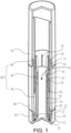
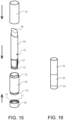
- a lipstick container in accordance with the invention comprises a base 10, a fixed tube 20, a lipstick assembly 60 and a cap 70 as discussed in detail below.
- the lipstick assembly 60 includes a support tube 30, a sleeving tube 40 and an ascending and descending tube 50.
- the fixed tube 20 is mounted on the base 10.
- the support tube 30 is put in the fixed tube 20, so a second end of the support tube 30 urges against the base 10.
- the sleeving tube 40 is then disposed on a first end of the support tube 30 distal the base 10.
- the ascending and descending tube 50 is put in the sleeving tube 40 and the support tube 30.
- the cap 70 is put on the sleeving tube 40 and secured to the fixed tube 20.
- the base 10 includes a close end.
- the fixed tube 20 includes a first axial channel 21 disposed through a center of the fixed tube 20 and an annular groove 22 is provided at an inner surface of a first end.
- An annular flange 23 is disposed on an outer surface of the first end.
- the support tube 30 includes a second axial channel 31 disposed through a center of the support tube 30.
- External threads 32 disposed on the support tube 30 adjacent the base 10 are screwed with the base 10.
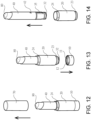
- the sleeving tube 40 includes a third axial channel 41 disposed through a center of the sleeving tube 40. A top of the sleeving tube 40 being flat or inclined and a bottom of the sleeving tube 40 being flat.
- the ascending and descending tube 50 includes a fourth axial channel 51 disposed through a center of the ascending and descending tube 50.
- a recess 52 forms at a first end of the ascending and descending tube 50 and a spiral groove portion 53 extends from the recess 52 towards a second end distal the recess 52.
- the spiral groove portion 53 communicates with the recess 52.
- the cap 70 includes an open end.
- the open end of the cap 70 further includes an annular slot 71 on an inner surface.
- the base 10 includes an open end and an annular trough 11 disposed on an inner surface of the open end distal the close end.
- the base 10 further comprises a projecting member 12 and a slip resistant member 13.
- the fixed tube 20 further comprises a plurality of stubs 24 on the outer surface distal the annular flange 23.
- An annular protrusion 33 formed on an outer surface of the support tube 30 distal the external threads 32.
- Internal threads 34 are formed on an inner surface of the first end of the support tube 30.
- a plurality of ridges 35 are formed on the outer surface and at a middle portion of the support tube 30.
- An annular shoulder 36 is disposed between the ridges 35 and the annular protrusion 33.
- At least one locking hole 42 is formed through the sleeving tube 40.
- the sleeving tube 40 further comprises an annular protuberance 43 circulated along an inner surface of the sleeving tube 40.
- a plurality of longitudinal ribs 54 are formed on an inner surface of the recess 52.
- the cap 70 includes a close end at another end.
- the projecting member 12 is disposed between an outer surface of the slip resistant member 13 and the inner surface of the base10.
- the external threads 32 disposed on the support tube 30 adjacent the base 10 are screwed with the projecting member 12 of the base 10.
- the annular flange 23 of the fixed tube 20 is secured with the annular trough 11 of the base 10.
- the fixed tube 20 is put on the support tube 30.
- the ridges 35 are correspondently mounted on annular grooves 22 of the fixed tube 20.
- the sleeving tube 35 is put in the fixed tube 20.
- the flat bottom of the sleeving tube 40 urges against the annular shoulder 36 of the support tube 30.
- the locking hole 42 receives the annular protrusion 33 of the support tube 30.
- the ascending and descending tube 50 is disposed through the third axial channel 41 of the sleeving tube 40 and then through the second axial channel 31 of the support tube 30.
- the annular protuberance 43 urges against an end of the recess 52 which is connected to the spiral groove portion 53.
- the spiral groove portion 53 is correspondently screwed with the internal threads 34 of the support tube 30.
- the cap 70 is put on the sleeving tube 40 and secured to the fixed tube 20 by the annular slot 71 snapping the stubs 24.
- the support tube 30 includes three ridges 35 on each side symmetrically disposed on two sides.
- the annular grooves 22 are disposed on the inner surface of the fixed tube 20 and correspondent to the ridges 35.
- the ridges 35 are mounted on and secured with the annular groves 22, so the support tube 30 and the fixed tube 20 are secured.
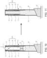
- a premade lipstick 81 is mounted on the lipstick assembly 60.
- the premade lipstick 81 is premade by hot filling a mold and then taken out after cooling down. Next, hold and rotate the fixed tube 20.
- the spiral groove portion 53 of the ascending and descending tube 50 rotates along the internal threads 34 of the support tube 30 towards the top of the sleeving tube 40, such that the ascending and descending tube 50 rotates towards the top of the sleeving tube 40.
- the recess 52 of the ascending and descending tube 50 receives the premade lipstick 81 by mounting the premade lipstick 81 onto the longitudinal ribs 54.
- the hot filling is not limited to only making the premade lipstick 81, and can be applied to other paste.
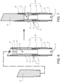
- steps of replacing the lipstick assembly 60 is shown.
- the lipstick 80 When the lipstick 80 is consumed, remove the cap 70 and the base 10.
- the base 10, the fixed tube 20 and the cap 70 can be reused. This not only protects the environment but also is eco-friendly with reduced waste.
Landscapes
- Cosmetics (AREA)
Claims (5)
- Lippenstiftbehälter zum Heißbefüllen mit einer auswechselbaren Lippenstiftanordnung, umfassend:eine Basis (10) mit einem geschlossenen Ende und einer ringförmigen Rinne (11), die an einer Innenfläche eines offenen Endes distal zum geschlossenen Ende angeordnet ist;ein feststehendes Rohr (20) mit einem ersten axialen Kanal (21), der durch eine Mitte des feststehenden Rohrs angeordnet ist, einer ringförmigen Nut (22), die an einer Innenfläche eines ersten Endes ausgebildet ist, einem ringförmigen Flansch (23), der an einer Außenfläche des ersten Endes angeordnet ist, und wobei der ringförmige Flansch des feststehenden Rohrs mit der ringförmigen Rinne der Basis befestigt ist;eine Lippenstiftanordnung (60), die ein Stützrohr (30), ein Mantelrohr (40) und ein aufsteigendes und absteigendes Rohr (50) umfasst, wobei das Stützrohr einen zweiten axialen Kanal (31), der durch eine Mitte des Stützrohrs angeordnet ist, einen ringförmigen Vorsprung (33), der an einer Außenfläche eines ersten Endes des Stützrohrs ausgebildet ist, ein Innengewinde (34), das an einer Innenfläche des ersten Endes ausgebildet ist, und eine Vielzahl von Rippen (35), die an der Außenfläche und an einem mittleren Abschnitt des Stützrohrs ausgebildet sind, und eine ringförmige Schulter (36), die zwischen den Rippen und dem ringförmigen Vorsprung angeordnet ist umfasst, wobei das feststehende Rohr auf das Stützrohr aufgesetzt ist, die Rippen an der ringförmigen Nut angebracht sind, wobei das Mantelrohr einen dritten axialen Kanal (41) aufweist, der durch eine Mitte des Mantelrohrs angeordnet ist, wobei eine Oberseite des Mantelrohrs flach oder geneigt ist, eine Unterseite des Mantelrohrs flach ist, und mindestens ein Verriegelungsloch (42), das durch das Mantelrohr hindurch ausgebildet ist, das feststehende Rohr auf das Mantelrohr aufgesetzt wird, die flache Unterseite des Mantelrohrs gegen die ringförmige Schulter des Stützrohrs drückt, das Verriegelungsloch den ringförmigen Vorsprung des Stützrohrs aufnimmt, wobei das aufsteigende und absteigende Rohr einen vierten axialen Kanal (51), der durch eine Mitte des aufsteigenden und absteigenden Rohrs hindurch angeordnet ist, eine Ausnehmung (52), die an einem ersten Ende ausgebildet ist, und einen spiralförmigen Rillenabschnitt (53), der mit der Aussparung in Verbindung steht und sich von der Aussparung zu einem zweiten, distalen Ende der Aussparung erstreckt, und eine Vielzahl von Längsrippen (54), die auf einer Innenfläche der Aussparung ausgebildet sind, enthält, wobei das aufsteigende und absteigende Rohr durch den dritten axialen Kanal des Mantelrohrs und durch den zweiten axialen Kanal des Stützrohrs angeordnet ist, wobei der spiralförmige Rillenabschnitt entsprechend mit den Innengewinden des Stützrohrs verschraubt ist;und eine Kappe (70), die ein geschlossenes Ende und ein offenes Ende aufweist, wobei das offene Ende der Kappe das Mantelrohr aufnimmt und an dem feststehenden Rohr befestigt ist.
- Lippenstiftbehälter nach Anspruch 1, wobei die Basis ferner ein rutschfestes Element (13) und ein vorstehendes Element (12) umfasst, wobei das vorstehende Element zwischen einer Außenfläche des rutschfesten Elements und der Innenfläche der Basis angeordnet ist, wobei Außengewinde (32), die auf dem Stützrohr angrenzend an die Basis angeordnet sind, mit dem vorstehenden Element der Basis verschraubt sind.
- Lippenstiftbehälter nach Anspruch 1, wobei das Mantelrohr ferner einen ringförmigen Vorsprung (43) aufweist, der entlang einer Innenfläche des Mantelrohrs umläuft, wobei der ringförmige Vorsprung gegen ein Ende der mit dem spiralförmigen Rillenabschnitt verbundenen Aussparung drückt.
- Lippenstiftbehälter nach Anspruch 1, wobei das aufsteigende und absteigende Rohr ferner einen Lippenstift (81) umfasst, der in der Aussparung aufgenommen und durch die Längsrippen befestigt ist.
- Lippenstiftbehälter nach Anspruch 1, wobei das feststehende Rohr ferner eine Vielzahl von Stümpfen (24) auf der äußeren Oberfläche distal des ringförmigen Flansches aufweist und die Kappe ferner einen ringförmigen Schlitz (71) in einer inneren Oberfläche des offenen Endes aufweist, wobei die Kappe auf das Mantelrohr aufgesetzt und an dem feststehenden Rohr durch den ringförmigen Schlitz befestigt wird, der die Stümpfe einschnappt.
Priority Applications (1)
| Application Number | Priority Date | Filing Date | Title |
|---|---|---|---|
| EP21213635.2A EP4193876B1 (de) | 2021-12-10 | 2021-12-10 | Lippenstiftbehälter zur heissbefüllung mit auswechselbarer lippenstiftanordnung |
Applications Claiming Priority (1)
| Application Number | Priority Date | Filing Date | Title |
|---|---|---|---|
| EP21213635.2A EP4193876B1 (de) | 2021-12-10 | 2021-12-10 | Lippenstiftbehälter zur heissbefüllung mit auswechselbarer lippenstiftanordnung |
Publications (3)
| Publication Number | Publication Date |
|---|---|
| EP4193876A1 EP4193876A1 (de) | 2023-06-14 |
| EP4193876C0 EP4193876C0 (de) | 2024-06-26 |
| EP4193876B1 true EP4193876B1 (de) | 2024-06-26 |
Family
ID=78829507
Family Applications (1)
| Application Number | Title | Priority Date | Filing Date |
|---|---|---|---|
| EP21213635.2A Active EP4193876B1 (de) | 2021-12-10 | 2021-12-10 | Lippenstiftbehälter zur heissbefüllung mit auswechselbarer lippenstiftanordnung |
Country Status (1)
| Country | Link |
|---|---|
| EP (1) | EP4193876B1 (de) |
Families Citing this family (1)
| Publication number | Priority date | Publication date | Assignee | Title |
|---|---|---|---|---|
| IT202300018024A1 (it) * | 2023-09-01 | 2025-03-01 | Cosmei S R L | Contenitore cosmetico di tipo esclusivamente a spinta, per prodotto cremoso, e procedimento di realizzazione di un cosmetico includente un prodotto cremoso |
Family Cites Families (1)
| Publication number | Priority date | Publication date | Assignee | Title |
|---|---|---|---|---|
| CN208524030U (zh) * | 2018-04-12 | 2019-02-22 | 濠福涂装(惠州)有限公司 | 一种密封唇膏管 |
-
2021
- 2021-12-10 EP EP21213635.2A patent/EP4193876B1/de active Active
Also Published As
| Publication number | Publication date |
|---|---|
| EP4193876C0 (de) | 2024-06-26 |
| EP4193876A1 (de) | 2023-06-14 |
Similar Documents
| Publication | Publication Date | Title |
|---|---|---|
| US4298036A (en) | Dispenser for stick solids | |
| US2076549A (en) | Jar | |
| US7422387B2 (en) | Stick-type cosmetic paint container | |
| EP3939472B1 (de) | Glasbehälter | |
| EP4193876B1 (de) | Lippenstiftbehälter zur heissbefüllung mit auswechselbarer lippenstiftanordnung | |
| US11800921B2 (en) | Lipstick container for hot filling with replaceable lipstick assembly | |
| AU2549192A (en) | Fill/invert package with specialized sealing, non-flow-through elevator system | |
| CN1057439C (zh) | 化妆品容器 | |
| US12022929B2 (en) | Cup module for a cosmetic stick mechanism, cup comprising such a module, refill comprising such a cup, and receptacle comprising such a cup or refill | |
| JP6415241B2 (ja) | 容器から分離可能なキャップ | |
| CN113490630A (zh) | 盖体、以及容器 | |
| JPS62135165A (ja) | ライナ−付き容器蓋及びその製造方法 | |
| GB2188616A (en) | Lipstick holders | |
| EP3412173B1 (de) | Wischer für kosmetikbehälter | |
| JP2001158456A (ja) | 液体収納容器及び該容器用リフィル容器 | |
| US12187495B2 (en) | Closure cap and vessel with such a closure cap and method for producing the closure cap | |
| JP2010029430A (ja) | 繰り出し容器のガス抜き機構 | |
| JP3468840B2 (ja) | 化粧料容器 | |
| JP2585872Y2 (ja) | リフィール容器 | |
| JP2002223847A (ja) | スティック状化粧料用容器 | |
| JP7510869B2 (ja) | レフィル容器、及び付け替え容器 | |
| JPH0536844Y2 (de) | ||
| CN222236982U (zh) | 包装组件 | |
| CN220924873U (zh) | 一种替换式化妆品罐 | |
| RU51970U1 (ru) | Бутылка и укупорочное устройство для нее |
Legal Events
| Date | Code | Title | Description |
|---|---|---|---|
| PUAI | Public reference made under article 153(3) epc to a published international application that has entered the european phase |
Free format text: ORIGINAL CODE: 0009012 |
|
| STAA | Information on the status of an ep patent application or granted ep patent |
Free format text: STATUS: REQUEST FOR EXAMINATION WAS MADE |
|
| 17P | Request for examination filed |
Effective date: 20220210 |
|
| AK | Designated contracting states |
Kind code of ref document: A1 Designated state(s): AL AT BE BG CH CY CZ DE DK EE ES FI FR GB GR HR HU IE IS IT LI LT LU LV MC MK MT NL NO PL PT RO RS SE SI SK SM TR |
|
| GRAP | Despatch of communication of intention to grant a patent |
Free format text: ORIGINAL CODE: EPIDOSNIGR1 |
|
| STAA | Information on the status of an ep patent application or granted ep patent |
Free format text: STATUS: GRANT OF PATENT IS INTENDED |
|
| RIC1 | Information provided on ipc code assigned before grant |
Ipc: A45D 40/00 20060101ALN20231223BHEP Ipc: A45D 40/16 20060101ALI20231223BHEP Ipc: A45D 40/04 20060101AFI20231223BHEP |
|
| INTG | Intention to grant announced |
Effective date: 20240124 |
|
| RIC1 | Information provided on ipc code assigned before grant |
Ipc: A45D 40/00 20060101ALN20240115BHEP Ipc: A45D 40/16 20060101ALI20240115BHEP Ipc: A45D 40/04 20060101AFI20240115BHEP |
|
| GRAS | Grant fee paid |
Free format text: ORIGINAL CODE: EPIDOSNIGR3 |
|
| GRAA | (expected) grant |
Free format text: ORIGINAL CODE: 0009210 |
|
| STAA | Information on the status of an ep patent application or granted ep patent |
Free format text: STATUS: THE PATENT HAS BEEN GRANTED |
|
| AK | Designated contracting states |
Kind code of ref document: B1 Designated state(s): AL AT BE BG CH CY CZ DE DK EE ES FI FR GB GR HR HU IE IS IT LI LT LU LV MC MK MT NL NO PL PT RO RS SE SI SK SM TR |
|
| REG | Reference to a national code |
Ref country code: GB Ref legal event code: FG4D |
|
| REG | Reference to a national code |
Ref country code: CH Ref legal event code: EP |
|
| REG | Reference to a national code |
Ref country code: DE Ref legal event code: R096 Ref document number: 602021014796 Country of ref document: DE |
|
| U01 | Request for unitary effect filed |
Effective date: 20240726 |
|
| U07 | Unitary effect registered |
Designated state(s): AT BE BG DE DK EE FI FR IT LT LU LV MT NL PT SE SI Effective date: 20240808 |
|
| PG25 | Lapsed in a contracting state [announced via postgrant information from national office to epo] |
Ref country code: HR Free format text: LAPSE BECAUSE OF FAILURE TO SUBMIT A TRANSLATION OF THE DESCRIPTION OR TO PAY THE FEE WITHIN THE PRESCRIBED TIME-LIMIT Effective date: 20240626 |
|
| PG25 | Lapsed in a contracting state [announced via postgrant information from national office to epo] |
Ref country code: GR Free format text: LAPSE BECAUSE OF FAILURE TO SUBMIT A TRANSLATION OF THE DESCRIPTION OR TO PAY THE FEE WITHIN THE PRESCRIBED TIME-LIMIT Effective date: 20240927 |
|
| PG25 | Lapsed in a contracting state [announced via postgrant information from national office to epo] |
Ref country code: NO Free format text: LAPSE BECAUSE OF FAILURE TO SUBMIT A TRANSLATION OF THE DESCRIPTION OR TO PAY THE FEE WITHIN THE PRESCRIBED TIME-LIMIT Effective date: 20240926 Ref country code: HR Free format text: LAPSE BECAUSE OF FAILURE TO SUBMIT A TRANSLATION OF THE DESCRIPTION OR TO PAY THE FEE WITHIN THE PRESCRIBED TIME-LIMIT Effective date: 20240626 Ref country code: GR Free format text: LAPSE BECAUSE OF FAILURE TO SUBMIT A TRANSLATION OF THE DESCRIPTION OR TO PAY THE FEE WITHIN THE PRESCRIBED TIME-LIMIT Effective date: 20240927 Ref country code: RS Free format text: LAPSE BECAUSE OF FAILURE TO SUBMIT A TRANSLATION OF THE DESCRIPTION OR TO PAY THE FEE WITHIN THE PRESCRIBED TIME-LIMIT Effective date: 20240926 |
|
| PG25 | Lapsed in a contracting state [announced via postgrant information from national office to epo] |
Ref country code: PL Free format text: LAPSE BECAUSE OF FAILURE TO SUBMIT A TRANSLATION OF THE DESCRIPTION OR TO PAY THE FEE WITHIN THE PRESCRIBED TIME-LIMIT Effective date: 20240626 |
|
| PG25 | Lapsed in a contracting state [announced via postgrant information from national office to epo] |
Ref country code: IS Free format text: LAPSE BECAUSE OF FAILURE TO SUBMIT A TRANSLATION OF THE DESCRIPTION OR TO PAY THE FEE WITHIN THE PRESCRIBED TIME-LIMIT Effective date: 20241026 |
|
| PG25 | Lapsed in a contracting state [announced via postgrant information from national office to epo] |
Ref country code: CZ Free format text: LAPSE BECAUSE OF FAILURE TO SUBMIT A TRANSLATION OF THE DESCRIPTION OR TO PAY THE FEE WITHIN THE PRESCRIBED TIME-LIMIT Effective date: 20240626 |
|
| PG25 | Lapsed in a contracting state [announced via postgrant information from national office to epo] |
Ref country code: RO Free format text: LAPSE BECAUSE OF FAILURE TO SUBMIT A TRANSLATION OF THE DESCRIPTION OR TO PAY THE FEE WITHIN THE PRESCRIBED TIME-LIMIT Effective date: 20240626 Ref country code: SK Free format text: LAPSE BECAUSE OF FAILURE TO SUBMIT A TRANSLATION OF THE DESCRIPTION OR TO PAY THE FEE WITHIN THE PRESCRIBED TIME-LIMIT Effective date: 20240626 |
|
| PG25 | Lapsed in a contracting state [announced via postgrant information from national office to epo] |
Ref country code: ES Free format text: LAPSE BECAUSE OF FAILURE TO SUBMIT A TRANSLATION OF THE DESCRIPTION OR TO PAY THE FEE WITHIN THE PRESCRIBED TIME-LIMIT Effective date: 20240626 Ref country code: SM Free format text: LAPSE BECAUSE OF FAILURE TO SUBMIT A TRANSLATION OF THE DESCRIPTION OR TO PAY THE FEE WITHIN THE PRESCRIBED TIME-LIMIT Effective date: 20240626 |
|
| PG25 | Lapsed in a contracting state [announced via postgrant information from national office to epo] |
Ref country code: SM Free format text: LAPSE BECAUSE OF FAILURE TO SUBMIT A TRANSLATION OF THE DESCRIPTION OR TO PAY THE FEE WITHIN THE PRESCRIBED TIME-LIMIT Effective date: 20240626 Ref country code: SK Free format text: LAPSE BECAUSE OF FAILURE TO SUBMIT A TRANSLATION OF THE DESCRIPTION OR TO PAY THE FEE WITHIN THE PRESCRIBED TIME-LIMIT Effective date: 20240626 Ref country code: RO Free format text: LAPSE BECAUSE OF FAILURE TO SUBMIT A TRANSLATION OF THE DESCRIPTION OR TO PAY THE FEE WITHIN THE PRESCRIBED TIME-LIMIT Effective date: 20240626 Ref country code: PL Free format text: LAPSE BECAUSE OF FAILURE TO SUBMIT A TRANSLATION OF THE DESCRIPTION OR TO PAY THE FEE WITHIN THE PRESCRIBED TIME-LIMIT Effective date: 20240626 Ref country code: IS Free format text: LAPSE BECAUSE OF FAILURE TO SUBMIT A TRANSLATION OF THE DESCRIPTION OR TO PAY THE FEE WITHIN THE PRESCRIBED TIME-LIMIT Effective date: 20241026 Ref country code: ES Free format text: LAPSE BECAUSE OF FAILURE TO SUBMIT A TRANSLATION OF THE DESCRIPTION OR TO PAY THE FEE WITHIN THE PRESCRIBED TIME-LIMIT Effective date: 20240626 Ref country code: CZ Free format text: LAPSE BECAUSE OF FAILURE TO SUBMIT A TRANSLATION OF THE DESCRIPTION OR TO PAY THE FEE WITHIN THE PRESCRIBED TIME-LIMIT Effective date: 20240626 |
|
| U20 | Renewal fee for the european patent with unitary effect paid |
Year of fee payment: 4 Effective date: 20241227 |
|
| PLBE | No opposition filed within time limit |
Free format text: ORIGINAL CODE: 0009261 |
|
| STAA | Information on the status of an ep patent application or granted ep patent |
Free format text: STATUS: NO OPPOSITION FILED WITHIN TIME LIMIT |
|
| 26N | No opposition filed |
Effective date: 20250327 |
|
| PG25 | Lapsed in a contracting state [announced via postgrant information from national office to epo] |
Ref country code: MC Free format text: LAPSE BECAUSE OF FAILURE TO SUBMIT A TRANSLATION OF THE DESCRIPTION OR TO PAY THE FEE WITHIN THE PRESCRIBED TIME-LIMIT Effective date: 20240626 |
|
| REG | Reference to a national code |
Ref country code: CH Ref legal event code: PL |
|
| PG25 | Lapsed in a contracting state [announced via postgrant information from national office to epo] |
Ref country code: CH Free format text: LAPSE BECAUSE OF NON-PAYMENT OF DUE FEES Effective date: 20241231 |
|
| PG25 | Lapsed in a contracting state [announced via postgrant information from national office to epo] |
Ref country code: IE Free format text: LAPSE BECAUSE OF NON-PAYMENT OF DUE FEES Effective date: 20241210 |
|
| PGFP | Annual fee paid to national office [announced via postgrant information from national office to epo] |
Ref country code: GB Payment date: 20251226 Year of fee payment: 5 |
|
| U20 | Renewal fee for the european patent with unitary effect paid |
Year of fee payment: 5 Effective date: 20251223 |