EP4193080B1 - Spaltdichtungseinrichtung - Google Patents
Spaltdichtungseinrichtung Download PDFInfo
- Publication number
- EP4193080B1 EP4193080B1 EP21748842.8A EP21748842A EP4193080B1 EP 4193080 B1 EP4193080 B1 EP 4193080B1 EP 21748842 A EP21748842 A EP 21748842A EP 4193080 B1 EP4193080 B1 EP 4193080B1
- Authority
- EP
- European Patent Office
- Prior art keywords
- rod
- seal device
- gap
- gap seal
- coupling
- Prior art date
- Legal status (The legal status is an assumption and is not a legal conclusion. Google has not performed a legal analysis and makes no representation as to the accuracy of the status listed.)
- Active
Links
Images


Classifications
-
- F—MECHANICAL ENGINEERING; LIGHTING; HEATING; WEAPONS; BLASTING
- F16—ENGINEERING ELEMENTS AND UNITS; GENERAL MEASURES FOR PRODUCING AND MAINTAINING EFFECTIVE FUNCTIONING OF MACHINES OR INSTALLATIONS; THERMAL INSULATION IN GENERAL
- F16J—PISTONS; CYLINDERS; SEALINGS
- F16J15/00—Sealings
- F16J15/44—Free-space packings
- F16J15/445—Free-space packings with means for adjusting the clearance
-
- F—MECHANICAL ENGINEERING; LIGHTING; HEATING; WEAPONS; BLASTING
- F04—POSITIVE - DISPLACEMENT MACHINES FOR LIQUIDS; PUMPS FOR LIQUIDS OR ELASTIC FLUIDS
- F04B—POSITIVE-DISPLACEMENT MACHINES FOR LIQUIDS; PUMPS
- F04B53/00—Component parts, details or accessories not provided for in, or of interest apart from, groups F04B1/00 - F04B23/00 or F04B39/00 - F04B47/00
- F04B53/14—Pistons, piston-rods or piston-rod connections
- F04B53/143—Sealing provided on the piston
-
- F—MECHANICAL ENGINEERING; LIGHTING; HEATING; WEAPONS; BLASTING
- F16—ENGINEERING ELEMENTS AND UNITS; GENERAL MEASURES FOR PRODUCING AND MAINTAINING EFFECTIVE FUNCTIONING OF MACHINES OR INSTALLATIONS; THERMAL INSULATION IN GENERAL
- F16J—PISTONS; CYLINDERS; SEALINGS
- F16J1/00—Pistons; Trunk pistons; Plungers
- F16J1/005—Pistons; Trunk pistons; Plungers obtained by assembling several pieces
Definitions
- the present invention relates to a gap sealing device according to the preamble of claim 1.
- a generic gap sealing device is known, for example, from EP 1 353 096 B1 or the EN 10 2008 041 176 A1 known.
- a sealing ring is used to seal a moving shaft or rod in the transition area between a high-pressure area and a low-pressure area of a guide chamber of a housing that guides the rod.
- the sealing ring encloses the shaft or rod and is partially deformed by the high pressure in the high-pressure area using a press ring, so that the deformation of the sealing ring reduces the gap between the sealing ring and the shaft to such an extent that it only allows the desired amount of fluid to leak through.
- the object of the present invention is to provide a gap sealing device which does not require such a sealing ring and without a press ring, while still requiring little manufacturing effort.
- the gap sealing device has a housing with a fluid-filled guide space and a multi-part piston which can be moved translationally and/or rotationally in the guide space.
- the piston forms an annular gap with a nominal gap width and an inner wall of the housing that delimits the guide chamber, separating a high-pressure area from a low-pressure area of the guide chamber.
- the piston has a stepped rod, a liner with a blind bore that is slipped over a stepped area of the rod, and a clutch.
- the rod can be tightened via the coupling and the bushing.
- the sleeve portion of the cylinder bush or the rod in its stepped region has at least one change in stiffness, in particular in the form of a material weakening.
- a gap width of the annular gap that is reduced compared to the nominal gap width can be adjusted in a range radially to the change in stiffness by tension-related expansion of an outer diameter of the sleeve section of the cylinder liner depending on the set clamping force.
- the gap size of the annular gap for sealing the high-pressure area from the low-pressure area of the guide chamber can be easily adjusted by varying the tension of the rod or the bushing, whereby the sealing effect of the gap sealing device or the amount of leakage can be easily varied.
- the rod can preferably be clamped relative to the cylinder bushing in order to expand an outer diameter of the sleeve section of the cylinder bushing.
- the rod can be clamped via the coupling and the cylinder bush.
- the rod is designed as a hollow rod with a through-bore in which a pull rod is received, wherein the pull rod is guided through the through-bore of the hollow rod and the hollow rod can be clamped by coupling a first end of the pull rod to the coupling and a second end of the pull rod to the bushing.
- the design of the rod as a hollow rod with a tension rod incorporated into it enables the rod or the bushing to be clamped in a simple manner.
- the coupling has a blind hole provided with an internal thread, wherein an external thread at the first end of the pull rod is screwed onto the internal thread and a clamping force acting in the axial direction is applied to the hollow rod by rotation about a longitudinal axis of the pull rod.
- the change in stiffness is designed as a material recess on the inner circumference of the stepped area of the hollow rod.
- Such a material recess can be easily introduced into the hollow rod.
- the rod is designed as a stepped solid rod.
- the rod can also be formed in one piece with the coupling.
- a tensioning of the rod relative to the cylinder bushing is also possible with such a design variant.
- the rod has a first end provided with an external thread, which is screwed into an internal thread of the cylinder bushing.
- the rod preferably has a second end provided with an external thread, which is screwed into an internal thread of the coupling.
- the change in stiffness is designed as a material recess on the inner circumference of the sleeve section of the cylinder liner.
- the material recess is preferably designed as an annular recess and thus enables a circumferentially uniform change in the outer diameter of the sleeve section of the cylinder liner.
- the bushing is adjustable relative to the pull rod axially to the longitudinal axis of the pull rod.
- top, bottom, left, right, front, back, etc. refer exclusively to the exemplary representation and position of the gap sealing device, housing, piston, rod, cylinder liner, coupling, pull rod and the like selected in the respective figures. These terms are not to be understood as limiting, i.e. these references can change due to different working positions or the mirror-symmetrical design or the like.
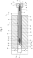
- the reference number 2 designates a housing which has a fluid-filled guide chamber 22 in which a multi-part piston 3 is movable in a translational and/or rotational manner.
- the housing 2 can be designed as a component of an oscillating plunger pump, in which the piston is oscillated in the longitudinal direction L in a Figure 1 illustrated translation direction T in the guide chamber 22 oscillatingly executes an oscillating movement in one working cycle (suction and pressure stroke).
- the piston 3 delimits a high-pressure region 23 of the guide chamber 22 from a low-pressure region 24 by forming an annular gap 9 with an inner wall 25 delimiting the guide chamber 22.
- the piston 3 is, as in Figure 1 is shown, is designed in several parts.
- the piston 3 has a stepped rod 4, here designed as a hollow rod, with a through hole 46 and a liner 5 slipped over a stepped area 42 of the hollow rod 4.
- the outer diameter of the cylinder bushing 5 corresponds to the outer diameter d K of a guide region 41 of the rod 4, while the stepped region 42 of the rod 4 is dimensioned in its outer diameter such that it rests against the inner wall of a sleeve section 52 of the cylinder bushing 5.
- the cylinder bushing 5 further comprises a blind bore 54 in the head portion 51 of the cylinder bushing 5, which serves to receive a pull rod 6 guided through the through bore 46 of the rod 4.
- a first end 61 of this pull rod 6 is received in a coupling 7, there in a blind bore 72.
- the hollow rod 4 can be clamped by bringing the coupling 7 closer to the bushing 5.
- the rod 4 designed as a hollow rod has a change in stiffness in its stepped region 42, here in the form of a material weakening 43.
- a change in stiffness can also be understood as a material section with a smaller modulus of elasticity.
- the sleeve portion 52 of the cylinder bush 5 has such a stiffness change 56.
- This change in stiffness 43, 56 makes it possible for a width of the annular gap 9 to be adjustable in a region radial to the change in stiffness 43, 56 of the hollow rod 4 by tension-related expansion of an outer diameter of the sleeve section 52 of the liner 5 depending on the set clamping force F from a nominal gap width S 0 to a gap width Sv reduced compared to the nominal gap width S 0 , as shown in Figure 2 is shown.
- the blind hole 72 of the coupling 7 is provided with an internal thread 73 and can thus be screwed onto an external thread 63 at the first end 61 of the pull rod 6.
- the distance between the coupling head 71 and the bushing 5 can be slightly reduced, which leads to a force acting in the axial direction on the hollow rod 4, which is adjustable depending on the angle of rotation covered by the coupling head 7 and the pitch of the threads 63, 73.
- the force acting in the axial direction on the hollow rod 4 causes the hollow rod 4 to deform.
- the location of this deformation as well as the direction of the deformation radially outward are determined.
- the pull rod 6 is preferably also provided with an external thread 63 in the region of its second end 62, onto which the bushing 5 can be screwed. As a result, the bushing 5 is also held on the pull rod 6 in the axial direction.
- the end face of the sleeve portion 52 of the cylinder bush 5 is separated by a gap 10 from the step 44 of the hollow rod 4 in the transition from the guide region 41 to the stepped region 42.
- the stiffness change 43 according to the Figures 1 to 3
- the embodiment shown is preferably designed as a material recess on the inner circumference of the stepped region 42 of the hollow rod 4.
- the stiffness change 56 is preferably designed as a material recess on the inner circumference of the sleeve section 52 of the cylinder bush 5.
- the stiffness change 43, 56 designed as a material recess is preferably designed as an annular recess.
- the bushing 5 is adjustable relative to the pull rod 6 axially to the longitudinal axis L of the pull rod 6.
- the deformation 55 on the outer diameter of the sleeve section 52 of the liner 5 is adjusted after adjustment of the clamping force via the coupling 7 so that the gap width is reduced compared to a nominal gap width S 0 so that in the exemplary use of the gap sealing device in an oscillating plunger pump it is possible to fill the high-pressure region 23 with the fluid in the suction stroke and to carry out a compression in the pressure stroke.
- the end face of the stepped region 42 of the hollow rod 4 is spaced from the inner end wall 53 of the cylinder bush 5 by a gap 10.
- the pressure is preferably between 150 bar and 8000 bar, particularly preferably between 1500 bar and 6000 bar.
- the fluid is preferably under a pressure of 1 to 16 bar.
- the deformation 55 in the sleeve section 52 of the cylinder liner 5 can be so large that the width of the remaining sealing gap S K approaches zero and thus a leakage of the fluid in the high-pressure state into the low-pressure region is completely or almost completely avoided.
- the rod 4 preferably has a first end 48 provided with an external thread, which is screwed into an internal thread of the bushing 5.
- the rod 4 also has a second end 49 provided with an external thread, which is screwed into the internal thread 73 of the coupling 7.
- Other coupling designs are also conceivable here, which enable the rod 4 to be braced or connected in the axial direction L.
- the two ends 48, 49 protrude from an end face of the guide region 1 of the rod 4 and have a smaller diameter than the diameter d K of the guide region 1.
- an outer surface of the stepped region 42 surrounded by the cylinder bushing 5 rests against the inner surface of the sleeve section 52 of the cylinder bushing 5, except for the change in stiffness 56 formed as a material recess.
- This stepped area 42 is then followed by the first end 47 of the rod 4, which is screwed into the head section 51 of the bushing 5.
- the stepped region 42 merges seamlessly into the first end 47, so that the sleeve section 52 of the cylinder bush 5, on whose inner surface the change in stiffness 56 is formed, does not touch the outer surface of the stepped region 42 surrounded by the cylinder bush 5.
- bracing of the rod 4 enables an initial reduction in the width of the annular gap 9 from the nominal gap width S 0 to a bracing gap width Sv, which is further reduced to a gap width S K when pressure is applied.
Landscapes
- Engineering & Computer Science (AREA)
- General Engineering & Computer Science (AREA)
- Mechanical Engineering (AREA)
- Chemical & Material Sciences (AREA)
- Combustion & Propulsion (AREA)
- Sealing Devices (AREA)
- Fluid-Damping Devices (AREA)
- Compressor (AREA)
- Details Of Reciprocating Pumps (AREA)
Description
- Die vorliegende Erfindung betrifft eine Spaltdichtungseinrichtung gemäß dem Oberbegriff des Anspruchs 1.
- Eine gattungsgemäße Spaltdichtungseinrichtung ist beispielsweise aus der
EP 1 353 096 B1 oder derDE 10 2008 041 176 A1 bekannt. - In dieser Druckschrift wird zur Abdichtung einer sich bewegenden Welle oder Stange im Übergangsbereich zwischen einem Hochdruckbereich und einem Niederdruckbereich eines die Stange führenden Führungsraums eines Gehäuses ein Dichtring eingesetzt, der die Welle oder Stange umschließt, und der mithilfe eine Pressringes durch den im Hochdruckbereich anliegenden Hochdruck partiell verformt wird, so dass durch die Verformung des Dichtrings der Spalt zwischen Dichtring und Welle so weit verkleinert wird, dass dieser nur noch die gewünschte Leckagemenge an Fluid durchlässt.
- Eine solche Spaltdichtungseinrichtung hat sich in der Praxis bewährt.
- Aufgabe der vorliegenden Erfindung ist es, eine Spaltdichtungseinrichtung bereitzustellen, die ohne einen solchen Dichtring und ohne Pressring auskommt, bei weiterhin geringem Fertigungsaufwand.
- Diese Aufgabe wird durch eine Spaltdichtungseinrichtung mit den Merkmalen des Anspruchs 1 gelöst.
- Die erfindungsgemäße Spaltdichtungseinrichtung weist ein Gehäuse mit einem fluidgefüllten Führungsraum sowie einen mehrteiligen Kolben auf, der translatorisch und/oder rotatorisch in dem Führungsraum bewegbar ist.
- Der Kolben grenzt unter Ausbildung eines Ringspaltes mit einer Nennspaltbreite mit einer den Führungsraum begrenzenden Innenwand des Gehäuses einen Hochdruckbereich von einem Niederdruckbereich des Führungsraumes ab.
- Der Kolben weist dabei eine gestufte Stange, eine über einen abgestuften Bereich der Stange übergestülpte Laufbuchse mit einer Sackbohrung und eine Kupplung auf.
- Die Stange ist über die Kupplung und die Laufbuchse verspannbar.
- Der Hülsenabschnitt der Laufbuchse oder die Stange in ihrem abgestuften Bereich weist wenigstens eine Steifigkeitsänderung, insbesondere in Gestalt einer Materialschwächung auf.
- Eine gegenüber der Nennspaltbreite reduzierte Spaltbreite des Ringspalts ist in einem Bereich radial zur Steifigkeitsänderung durch verspannungsbedingtes Aufweiten eines Außendurchmessers des Hülsenabschnitts der Laufbuchse in Abhängigkeit von der eingestellten Spannkraft einstellbar.
- Mit einer solchermaßen ausgebildeten Spaltdichtungseinrichtung ist durch Variation der Verspannung der Stange bzw. der Laufbuchse das Spaltmaß des Ringspaltes zur Abdichtung des Hochdruckbereichs vom Niederdruckbereich des Führungsraums in einfacher Weise einstellbar, wodurch die Dichtwirkung der Spaltdichtungseinrichtung bzw. die Menge an Leckage in einfacher Weise variierbar ist.
- Vorteilhafte Ausführungsvarianten der Erfindung sind Gegenstand der Unteransprüche.
- Die Stange ist zur Aufweitung eines Außendurchmessers des Hülsenabschnitts der Laufbuchse bevorzugt relativ zur Laufbuchse verspannbar.
- Gemäß einer ersten bevorzugten Weiterbildung ist die Stange über die Kupplung und die Laufbuchse verspannbar.
- Gemäß einer vorteilhaften Ausführungsvariante ist die Stange dazu als Hohlstange mit einer Durchgangsbohrung ausgebildet, in der eine Zugstange aufgenommen ist, wobei die Zugstange durch die Durchgangsbohrung der Hohlstange geführt und die Hohlstange durch Kopplung eines ersten Endes der Zugstange mit der Kupplung und eines zweiten Endes der Zugstange mit der Laufbuchse verspannbar ist.
- Die Ausbildung der Stange als Hohlstange mit darin aufgenommener Zugstange ermöglicht in einfacher Weise eine Verspannung der Stange bzw. der Laufbuchse.
- Gemäß einer vorteilhaften Weiterbildung weist die Kupplung ein mit einem Innengewinde versehenes Sackloch auf, wobei ein Außengewinde am ersten Ende der Zugstange auf das Innengewinde aufgedreht und durch Rotation um eine Längsachse der Zugstange eine in axialer Richtung wirkende Spannkraft auf die Hohlstange aufgebracht wird.
- Dadurch ist durch Drehen der Kupplung in einfacher Weise der Druck auf die Hohlstange und damit das Maß des Ringspalts einstellbar.
- Gemäß einer weiteren Ausführungsvariante ist die Steifigkeitsänderung als Materialausnehmung am Innenumfang des abgestuften Bereichs der Hohlstange ausgebildet.
- Eine solche Materialausnehmung kann in einfacher Weise in die Hohlstange eingebracht werden.
- In einer alternativen Ausführungsvariante ist die Stange als abgestufte Vollstange ausgebildet.
- Die Stange kann dabei insbesondere auch einstückig mit der Kupplung ausgebildet sein.
- Eine Verspannung der Stange relativ zur Laufbuchse ist auch mit einer solchen Ausführungsvariante möglich.
- Zur Verspannung weist dabei in einer bevorzugten Ausführungsvariante die Stange ein mit einem Außengewinde versehenes erstes Ende auf, das in ein Innengewinde der Laufbuchse eingeschraubt ist.
- Zur Verspannung mit einer als separates Bauteil ausgebildeten Kupplung weist die Stange bevorzugt ein mit einem Außengewinde versehenes zweites Ende auf, das in ein Innengewinde der Kupplung eingeschraubt ist.
- Gemäß einer alternativen Ausführungsvariante ist die Steifigkeitsänderung als Materialausnehmung am Innenumfang des Hülsenabschnitts der Laufbuchse ausgebildet.
- Auch dadurch kann die gewünschte Aufweitung des Außendurchmessers in einfacher Weise erreicht werden.
- Die Materialausnehmung ist dabei bevorzugt als ringförmige Aussparung ausgebildet und ermöglicht so eine umfänglich gleiche Änderung des Außendurchmessers des Hülsenabschnitts der Laufbuchse.
- Gemäß einer weiteren vorteilhaften Ausführungsvariante ist die Laufbuchse relativ zur Zugstange axial zur Längsachse der Zugstange verstellbar.
- Dies ermöglicht die Einstellung der Position der Außendurchmesseraufweitung des Hülsenabschnitts der Laufbuchse in Axialrichtung der Zugstange.
- Nachfolgend werden bevorzugte Ausführungsbeispiele anhand der beiliegenden Zeichnungen näher erläutert. Es zeigen:
- Figur 1
- eine Schnittansicht durch eine Ausführungsvariante einer erfindungsgemäßen Spaltdichtungseinrichtung,
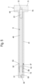
- Figur 2
- eine Teilschnittansicht der in
Figur 1 dargestellten Spaltdichtungseinrichtung im verspannten Zustand, - Figur 3
- eine der
Figur 2 entsprechende Darstellung der Spaltdichtungseinrichtung mit Darstellung des Druckabfalls vor dem aufgeweiteten Bereich des Hülsenabschnitts der Laufbuchse, - Figur 4
- eine Detaildarstellung des in
Figur 3 mit IV bezeichneten Ausschnitts unter der zusätzlichen Verformung durch den anstehenden Betriebsdruck, - Figuren 5 und 6
- der
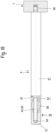
Figur 1 entsprechende alternative Ausführungsvariante einer erfindungsgemäßen Spaltdichtungseinrichtung mit Steifigkeitsänderung im Hülsenabschnitt der Laufbuchse, und - Figuren 7 und 8
- nochmals alternative Ausführungsvariante einer erfindungsgemäßen Spaltdichtungseinrichtung mit als Vollstange ausgebildeter Stange.
- In der nachfolgenden Figurenbeschreibung beziehen sich Begriffe wie oben, unten, links, rechts, vorne, hinten usw. ausschließlich auf die in den jeweiligen Figuren gewählte beispielhafte Darstellung und Position der Spaltdichtungseinrichtung, Gehäuse, Kolben, Stange, Laufbuchse, Kupplung, Zugstange und dergleichen. Diese Begriffe sind nicht einschränkend zu verstehen, d.h., durch verschiedene Arbeitsstellungen oder die spiegelsymmetrische Auslegung oder dergleichen können sich diese Bezüge ändern.
- In den
Figuren 1 bis 3 ist mit dem Bezugszeichen 2 ein Gehäuse bezeichnet, das einen Fluid gefüllten Führungsraum 22 aufweist, in dem ein mehrteiliger Kolben 3 translatorisch und/oder rotatorisch bewegbar ist. - Das Gehäuse 2 kann dabei als Bestandteil einer oszillierenden Plungerpumpe ausgebildet sein, bei der der Kolben in Längsrichtung L in einer in
Figur 1 dargestellten Translationsrichtung T in den Führungsraum 22 oszillierend in einem Arbeitstakt (Saug- und Druckhub) eine oszillierende Bewegung ausführt. - Der Kolben 3 grenzt dabei unter Ausbildung eines Ringspaltes 9 mit einer den Führungsraum 22 begrenzenden Innenwand 25 einen Hochdruckbereich 23 des Führungsraums 22 von einem Niederdruckbereich 24 ab.
- Der Kolben 3 ist dabei, wie in
Figur 1 dargestellt ist, mehrteilig ausgeführt. Der Kolben 3 weist eine gestufte, hier als Hohlstange ausgebildete Stange 4 mit einer Durchgangsbohrung 46 auf sowie eine über einen abgestuften Bereich 42 der Hohlstange 4 übergestülpte Laufbuchse 5. - Der Außendurchmesser der Laufbuchse 5 entspricht dabei dem Außendurchmesser dK eines Führungsbereiches 41 der Stange 4, während der abgestufte Bereich 42 der Stange 4 in seinem Außendurchmesser so bemessen ist, dass dieser in einem Hülsenabschnitt 52 der Laufbuchse 5 an dessen Innenwand anliegt.
- Die Laufbuchse 5 weist des Weiteren eine Sackbohrung 54 im Kopfabschnitt 51 der Laufbuchse 5 auf, die der Aufnahme einer durch die Durchgangsbohrung 46 der Stange 4 geführten Zugstange 6 dient.
- Ein erstes Ende 61 dieser Zugstange 6 ist dabei in einer Kupplung 7, dort in einer Sackbohrung 72 aufgenommen. Durch die Kopplung des ersten Endes 61 der Zugstange 6 mit der Kupplung 7 und eines zweiten Endes 62 der Zugstange 6 mit der Laufbuchse 5 ist die Hohlstange 4 durch Annähern der Kupplung 7 an die Laufbuchse 5 verspannbar.
- Wie in der in
Figur 1 gezeigten Ausführungsvariante dargestellt ist, weist die als Hohlstange ausgebildete Stange 4 in ihrem abgestuften Bereich 42 eine Steifigkeitsänderung, hier in Gestalt einer Materialschwächung 43 auf. - Als Steifigkeitsänderung kann neben der gezeigten Materialschwächung in Gestalt einer gezielten Wegnahme von Material beispielsweise auch ein Materialabschnitt mit kleinerem Elastizitätsmodul verstanden werden.
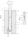
- Bei der in den
Figuren 5 und6 gezeigten alternativen Ausführungsvariante weist der Hülsenabschnitt 52 der Laufbuchse 5 eine solche Steifigkeitsänderung 56 auf. - Durch diese Steifigkeitsänderung 43, 56 ist es ermöglicht, dass eine Breite des Ringspaltes 9 in einem Bereich radial zur Steifigkeitsänderung 43, 56 der Hohlstange 4 durch verspannungsbedingtes Aufweiten eines Außendurchmessers des Hülsenabschnitts 52 der Laufbuchse 5 in Abhängigkeit von der eingestellten Spannkraft F von einer Nennspaltbreite S0 auf eine gegenüber der Nennspaltbreite S0 reduzierte Spaltbreite Sv einstellbar ist, wie es in
Figur 2 dargestellt ist. - Während bei der in
Figur 5 und6 gezeigten Ausführungsvariante der Hülsenabschnitt 52 der Laufbuchse 5 durch Anziehen der Laufbuchse 5 relativ zur Kupplung 7 im Bereich der Steifigkeitsänderung 56 direkt aufgeweitet wird, drückt bei der in denFiguren 1 bis 3 gezeigten Ausführungsvariante der mit der Steifigkeitsänderung 43 versehene abgestufte Bereich 42 der Hohlstange 4 durch die Spannkraft bedingt radial nach außen gegen den Hülsenabschnitt 52 der Laufbuchse 5, was zur Aufweitung des Außendurchmessers des Hülsenabschnitts 52 der Laufbuchse 5 in diesem Bereich führt. - Zur Erzeugung der Verspannung der Hohlstange 4 ist gemäß einer bevorzugten Ausführungsvariante das Sackloch 72 der Kupplung 7 mit einem Innengewinde 73 versehen und so auf ein Außengewinde 63 am ersten Ende 61 der Zugstange 6 aufdrehbar.
- Durch Rotation des Kupplungskopfes 71 der Kupplung 7 in einer Rotationsrichtung R um eine Längsachse L der Zugstange 6 kann so der Abstand zwischen dem Kupplungskopf 71 und der Laufbuchse 5 geringfügig verringert werden, was zu einer in axialer Richtung wirkenden Kraft auf die Hohlstange 4 führt, die abhängig von dem zurückgelegtem Drehwinkel des Kupplungskopfes 7 und der Steigung der Gewinde 63, 73 einstellbar ist.
- Die in axialer Richtung wirkende Kraft auf die Hohlstange 4 führt dazu, dass die Hohlstange 4 sich verformen muss.
- Durch die Ausbildung der Steifigkeitsänderung 43 wird der Ort dieser Verformung sowie die Richtung der Verformung radial nach außen festgelegt.
- Diese Verformung radial nach außen führt zu einer Aufweitung des Außendurchmessers des Hülsenabschnitts 52 der Laufbuchse 5, wie sie schematisch in den
Figuren 2 dargestellt ist. - Die Zugstange 6 ist im Bereich ihres zweiten Endes 62 bevorzugt ebenfalls mit einem Außengewinde 63 versehen, auf das die Laufbuchse 5 aufschraubbar ist. Dadurch ist die Laufbuchse 5 ebenfalls in axialer Richtung an der Zugstange 6 gehalten.
- Die Übertragung der über die Kupplung 7 ausgeübte in axialer Richtung wirkende Kraft erfolgt hier durch eine Innenstirnwand 53 am Kopfabschnitt 51 der Laufbuchse 5, an der eine Andruckfläche 47 des abgestuften Bereichs 42 der Hohlstange 4 anliegt.
- Die Stirnfläche des Hülsenabschnitts 52 der Laufbuchse 5 ist durch einen Spalt 10 von der Stufe 44 der Hohlstange 4 im Übergang vom Führungsbereich 41 zum abgestuften Bereich 42 getrennt.
- Die Steifigkeitsänderung 43 gemäß der in den
Figuren 1 bis 3 gezeigten Ausführungsvariante ist bevorzugt als Materialausnehmung am Innenumfang des abgestuften Bereichs 42 der Hohlstange 4 ausgebildet. - Bei der in den
Figuren 5 und6 gezeigten Ausführungsvariante ist die Steifigkeitsänderung 56 bevorzugt als Materialausnehmung am Innenumfang des Hülsenabschnitts 52 der Laufbuchse 5 ausgebildet. - Die als Materialausnehmung ausgebildete Steifigkeitsänderung 43, 56 ist dabei bevorzugt als ringförmige Aussparung ausgebildet.
- Denkbar ist auch, entlang der Längsachse L, wie in
Figur 2 dargestellt, mehrere Steifigkeitsänderungen vorzunehmen, um so die Dichtwirkung auf mehrere Druckabbauzonen zu verteilen und den Führungsanteil des Kolbens 3 zu erhöhen. - Gemäß einer weiteren Ausführungsvariante ist die Laufbuchse 5 relativ zur Zugstange 6 axial zur Längsachse L der Zugstange 6 verstellbar.
- Die Verformung 55 am Außendurchmesser des Hülsenabschnitts 52 der Laufbuchse 5 ist nach Einstellung der Spannkraft über die Kupplung 7 so eingestellt, dass die Spaltbreite gegenüber einer Nennspaltbreite S0 so verkleinert ist, dass es im beispielhaften Einsatz der Spaltdichtungseinrichtung in einer oszillierenden Plungerpumpe möglich ist, im Saughub den Hochdruckbereich 23 mit dem Fluid zu befüllen und im Druckhub eine Kompression durchzuführen.
- Bei diesem Druckhub erfolgt, wie es in den
Figuren 3 und 4 dargestellt ist, zusätzlich eine weitere Verformung des Hülsenabschnitts 52 der Laufbuchse 5, bedingt durch den auf die Stirnfläche 57 der Laufbuchse 5 wirkenden Hochdruck, wodurch der Ringspalt 9 auf eine weiter reduzierte Spaltbreite SK reduziert wird und so die Abdichtung des Fluids im den Hochdruckbereich 23 bildenden Kompressionsraum zusätzlich begünstigt und eine Leckage weiter reduziert wird. - In
Figur 3 ist zur Verdeutlichung des Druckabbaus an der Innenumfangsfläche des den Führungsraum 22 begrenzenden Körpers 21 des Gehäuses 2 schematisch ein Druckverlauf p dargestellt, der den auf die Innenfläche des Gehäuses 2 wirkenden, allmählich abfallenden Hochdruck p darstellen soll, der gemäß einer Funktion p = f(x) von der Erstreckung des Spaltes S in Längsrichtung X abhängig ist. - Denkbar ist prinzipiell auch der Einsatz einer solchen Spaltdichtungseinrichtung bei rotierenden Systemen, bei denen der Kolben 3 im Gehäuse 2 rotatorisch bewegt wird und ein unter Druck stehender Raum, hier der Hochdruckbereich 23, gegenüber einem Niederdruckbereich 24 abgedichtet werden muss.
- Bei der in den
Figuren 5 und6 gezeigten Ausführungsvariante, bei der die Steifigkeitsänderung 56 am Innenumfang des Hülsenabschnitts 52 der Laufbuchse 5 vorgesehen ist, ist die Andruckfläche 47, gegen die die durch die Kupplung 7 ausgeübte Spannkraft ausgeübt wird, gleich der Stufe 44 der Hohlstange 4 im Übergangsbereich zwischen Führungsbereich 41 und abgestuftem Bereich 42. - Hier ist die Stirnfläche des abgestuften Bereichs 42 der Hohlstange 4 durch einen Spalt 10 von der Innenstirnwand 53 der Laufbuchse 5 beabstandet.
- In
Figur 6 sind darüber hinaus zwei unterschiedlich große Verformungen 55, 55' dargestellt, wobei die Verformung 55 durch die Verspannung und die Verformung 55' durch die zusätzliche Kompression des unter Hochdruck stehenden Fluids erzeugt ist. - Der Druck beträgt dabei vorzugsweise zwischen 150 bar und 8000 bar, besonders bevorzugt zwischen 1500 bar und 6000 bar. Im Niederdruckbereich 24 steht das Fluid vorzugsweise unter einem Druck von 1 bis 16 bar.
- Bedingt durch den Hochdruck im Hochdruckbereich 23, der über einen Hochdruckraum 8 sich in den Führungsraum 22 des Gehäuses 2 erstreckt, führt diese Druckdifferenz zu einer leichten Verformung auch an der Innenseite des Gehäuses 2, wie es in
Figur 4 dargestellt ist. - Die Verformung 55 im Hülsenabschnitt 52 der Laufbuchse 5 kann dabei je nach anstehendem Hochdruck so groß sein, dass die Breite des verbleibenden Dichtspaltes SK gegen Null geht und damit eine Leckage des Fluids im Hochdruckzustand in den Niederdruckbereich vollständig oder nahezu vollständig vermieden wird.
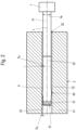
- In den
Figuren 7 und8 sind zwei weitere, nochmals alternative Ausführungsvariante einer erfindungsgemäßen Spaltdichtungseinrichtung, in diesem Fall mit als Vollstange bzw. massiv ausgebildeter Stange dargestellt. - Bei diesen Varianten weist die Stange 4 bevorzugt ein mit einem Außengewinde versehenes erstes Ende 48 auf, das in ein Innengewinde der Laufbuchse 5 eingeschraubt ist.
- Entsprechend weist die Stange 4 auch ein mit einem Außengewinde versehenes zweites Ende 49 auf, das in das Innengewinde 73 der Kupplung 7 eingeschraubt ist. Denkbar sind auch hier andere Kopplungsausgestaltungen, die ein Verspannen oder Anbinden der Stange 4 in Axialrichtung L ermöglichen.
- Die beiden Enden 48, 49 stehen dabei aus einer Stirnfläche des Führungsbereiches 1 der Stange 4 vor und weisen einen gegenüber dem Durchmesser dK des Führungsbereiches 1 geringeren Durchmesser auf.
- Bei der in
Figur 7 gezeigten Ausführungsvariante liegt eine Außenmantelfläche des von der Laufbuchse 5 ummantelten abgestuften Bereichs 42 bis auf die als Materialausnehmung ausgebildete Steifigkeitsänderung 56 an der Innenfläche des Hülsenabschnitts 52 der Laufbuchse 5 an. - An diesen abgestuften Bereich 42 schließt sich dann das erste Ende 47 der Stange 4 an, das in den Kopfabschnitt 51 der Laufbuchse 5 eingeschraubt ist.
- Bei der in
Figur 8 gezeigten Ausführungsvariante geht der abgestufte Bereich 42 stufenlos in das erste Ende 47 über, so dass der Hülsenabschnitts 52 der Laufbuchse 5, an dessen Innenmantelfläche die Steifigkeitsänderung 56 ausgebildet ist, die Außenmantelfläche des von der Laufbuchse 5 ummantelten abgestuften Bereichs 42 nicht berührt. - Denkbar ist des Weiteren auch, die Stange einstückig mit der Kupplung auszubilden.
- Wichtig ist auch bei diesen Ausführungsvarianten, dass durch die Verspannung der Stange 4 eine erste Verkleinerung der Breite des Ringspaltes 9 von der Nennspaltbreite S0 auf eine verspannte Spaltbreite Sv ermöglicht ist, die bei Druckbeaufschlagung sich weiter auf eine Spaltbreite SK reduziert.
-
- 2
- Gehäuse
- 21
- Körper
- 22
- Führungsraum
- 23
- Hochdruckbereich
- 24
- Niederdruckbereich
- 3
- Stange
- 4
- Stange
- 41
- Führungsbereich
- 42
- abgestufter Bereich
- 43
- Steifigkeitsänderung
- 44
- Stufe
- 45
- erste Stirnfläche
- 46
- Durchgangsbohrung
- 47
- Andruckfläche
- 48
- erstes Ende
- 49
- zweites Ende
- 5
- Laufbuchse
- 51
- Kopfabschnitt
- 52
- Hülsenabschnitt
- 53
- Innenstirnwand
- 54
- Sackloch
- 55
- Verformung
- 56
- Steifigkeitsänderung
- 57
- Stirnfläche
- 6
- Zugstange
- 61
- erstes Ende
- 62
- zweites Ende
- 63
- Außengewinde
- 7
- Kupplung
- 71
- Kupplungskopf
- 72
- Sackloch
- 73
- Innengewinde
- 8
- Hochdruckraum
- 9
- Ringspalt
- 10
- Spalt
- S
- Spaltbreite
- S0
- Nennspaltbreite
- Sv
- Spaltbreite verspannt
- SK
- Spaltbreite verspannt und bei anliegendem Hochdruck
- L
- Längsachse
- T
- Translationsrichtung
- R
- Rotationsrichtung
- X
- Richtung
- Y
- Richtung
- dK
- Durchmesser
- p
- Druck
Claims (13)
- Spaltdichtungseinrichtung, aufweisendein Gehäuse (2) mit einem fluidgefüllten Führungsraum (22),einen mehrteiligen Kolben (3), der translatorisch und/oder rotatorisch in dem Führungsraum (22) bewegbar ist,wobei der Kolben (3) unter Ausbildung eines Ringspaltes (9) mit einer Nennspaltbreite (S0) mit einer den Führungsraum (22) begrenzenden Innenwand (25) einen Hochdruckbereich (23) von einem Niederdruckbereich (24) des Führungsraumes (22) abgrenzt,dadurch gekennzeichnet, dassder Kolben (3) eine gestufte Stange (4), eine über einen abgestuften Bereich (42) der Stange (4) übergestülpte Laufbuchse (5) mit einer Sackbohrung (54) und eine Kupplung (7) aufweist,wobei im abgestuften Bereich (42) der Stange (4) oder einem Hülsenabschnitt (52) der Laufbuchse (5) wenigstens eine Steifigkeitsänderung (43, 56) vorgesehen ist,wobei eine gegenüber der Nennspaltbreite (S0) reduzierte Spaltbreite (Sv) des Ringspalts (9) in einem Bereich radial zur Steifigkeitsänderung (43, 56) durch verspannungsbedingtes Aufweiten eines Außendurchmessers des Hülsenabschnitts (52) der Laufbuchse (5) in Abhängigkeit von der eingestellten Spannkraft (F) einstellbar ist.
- Spaltdichtungseinrichtung nach Anspruch 1, dadurch gekennzeichnet, dass die Stange (4) relativ zur Laufbuchse (5) verspannbar ist.
- Spaltdichtungseinrichtung nach Anspruch 1 oder 2, dadurch gekennzeichnet, dass die Stange (4) über die Kupplung (7) und die Laufbuchse (5) verspannbar ist.
- Spaltdichtungseinrichtung nach Anspruch 3, dadurch gekennzeichnet, dass die Stange (4) als Hohlstange mit einer Durchgangsbohrung (46) ausgebildet ist, in der eine Zugstange (6) aufgenommen ist, wobei die Zugstange (6) durch die Durchgangsbohrung (46) der Stange (4) geführt und die Stange (4) durch Kopplung eines ersten Endes (61) der Zugstange (6) mit der Kupplung (7) und eines zweiten Endes (62) der Zugstange (6) mit der Laufbuchse (5) verspannbar ist.
- Spaltdichtungseinrichtung nach Anspruch 4, dadurch gekennzeichnet, dass die Kupplung (7) ein mit einem Innengewinde (73) versehenes Sackloch (72) aufweist, wobei ein Außengewinde (63) am ersten Ende (61) der Zugstange (6) auf das Innengewinde (73) aufgedreht und durch Rotation um eine Längsachse (L) der Zugstange (6) ein in axialer Richtung der Zugstange (6) wirkender Druck auf die als Hohlstange ausgebildete Stange (4) einstellbar ist.
- Spaltdichtungseinrichtung nach einem der vorstehenden Ansprüche, dadurch gekennzeichnet, dass die Steifigkeitsänderung (43) als Materialausnehmung am Innenumfang des abgestuften Bereichs (42) der Stange (4) ausgebildet ist.
- Spaltdichtungseinrichtung nach einem der Ansprüche 4 bis 6, dadurch gekennzeichnet, dass die Laufbuchse (5) relativ zur Zugstange (6) axial zur Längsachse (L) der Zugstange (6) verstellbar ist.
- Spaltdichtungseinrichtung nach Anspruch 1 oder 2, dadurch gekennzeichnet, dass die Stange (4) als abgestufte Vollstange ausgebildet ist.
- Spaltdichtungseinrichtung nach einem der Ansprüche 1 bis 5 oder 8, dadurch gekennzeichnet, dass die Steifigkeitsänderung (56) als Materialausnehmung am Innenumfang des Hülsenabschnitts (52) der Laufbuchse (5) ausgebildet ist.
- Spaltdichtungseinrichtung nach Anspruch 6 oder 9, dadurch gekennzeichnet, dass die Steifigkeitsänderung (43, 56) als ringförmige Aussparung ausgebildet ist.
- Spaltdichtungseinrichtung nach einem der Ansprüche 8 bis 10, dadurch gekennzeichnet, dass die Stange (4) ein mit einem Außengewinde versehenes erstes Ende (48) aufweist, das in ein Innengewinde der Laufbuchse (5) eingeschraubt ist.
- Spaltdichtungseinrichtung nach einem der Ansprüche 8 bis 11, dadurch gekennzeichnet, dass die Stange (4) ein mit einem Außengewinde versehenes zweites Ende (49) aufweist, das in ein Innengewinde (73) der Kupplung (7) eingeschraubt ist.
- Spaltdichtungseinrichtung nach einem der Ansprüche 8 bis 11, dadurch gekennzeichnet, dass die Stange (4) einstückig mit der Kupplung (7) ausgebildet ist.
Priority Applications (2)
| Application Number | Priority Date | Filing Date | Title |
|---|---|---|---|
| RS20241241A RS66121B1 (sr) | 2020-08-07 | 2021-07-22 | Uređaj za zaptivanje zazora |
| HRP20241529TT HRP20241529T1 (hr) | 2020-08-07 | 2021-07-22 | Naprava za brtvljenje pukotina |
Applications Claiming Priority (2)
| Application Number | Priority Date | Filing Date | Title |
|---|---|---|---|
| DE102020120929.0A DE102020120929A1 (de) | 2020-08-07 | 2020-08-07 | Spaltdichtungseinrichtung |
| PCT/EP2021/070517 WO2022028906A1 (de) | 2020-08-07 | 2021-07-22 | Spaltdichtungseinrichtung |
Publications (2)
| Publication Number | Publication Date |
|---|---|
| EP4193080A1 EP4193080A1 (de) | 2023-06-14 |
| EP4193080B1 true EP4193080B1 (de) | 2024-08-28 |
Family
ID=77155769
Family Applications (1)
| Application Number | Title | Priority Date | Filing Date |
|---|---|---|---|
| EP21748842.8A Active EP4193080B1 (de) | 2020-08-07 | 2021-07-22 | Spaltdichtungseinrichtung |
Country Status (13)
| Country | Link |
|---|---|
| US (1) | US12000490B2 (de) |
| EP (1) | EP4193080B1 (de) |
| JP (1) | JP2023537304A (de) |
| AU (1) | AU2021321978A1 (de) |
| DE (1) | DE102020120929A1 (de) |
| DK (1) | DK4193080T3 (de) |
| ES (1) | ES2993895T3 (de) |
| FI (1) | FI4193080T3 (de) |
| HR (1) | HRP20241529T1 (de) |
| PL (1) | PL4193080T3 (de) |
| PT (1) | PT4193080T (de) |
| RS (1) | RS66121B1 (de) |
| WO (1) | WO2022028906A1 (de) |
Family Cites Families (13)
| Publication number | Priority date | Publication date | Assignee | Title |
|---|---|---|---|---|
| US2574109A (en) | 1949-02-17 | 1951-11-06 | Jr Frank A Kane | Device for adjustably interfitting two coactive members |
| GB1324080A (en) * | 1969-12-15 | 1973-07-18 | Ici Ltd | Pistons |
| GB1462145A (en) | 1974-11-15 | 1977-01-19 | Hammelmann Paul Maschf | High-pressure plunger pumps |
| DE2615530C3 (de) | 1976-04-09 | 1980-02-28 | Paul Hammelmann Maschinenfabrik, 4740 Oelde | Hochdruckplungerpumpe |
| JPS578917Y2 (de) * | 1977-09-16 | 1982-02-20 | ||
| US4734013A (en) * | 1986-02-18 | 1988-03-29 | V-Tech Industries Inc. | Rotary pressure intensifier |
| JPH046575U (de) * | 1990-04-24 | 1992-01-21 | ||
| US5740718A (en) * | 1996-10-17 | 1998-04-21 | Binks Manufacturing Company | Modular piston rod assembly with integrated high-wear components |
| DE10210317A1 (de) * | 2002-03-08 | 2003-09-25 | Bosch Gmbh Robert | Hochdruckelement für Einspritzanlagen mit verringerter Leckage |
| DE10215311A1 (de) | 2002-04-08 | 2003-11-06 | Hammelmann Paul Maschf | Dichtungseinrichtung |
| JP2004019761A (ja) * | 2002-06-14 | 2004-01-22 | Kurabo Ind Ltd | シリンジ装置 |
| DE102008041176A1 (de) * | 2008-08-12 | 2010-02-18 | Robert Bosch Gmbh | Hochdruckpumpe |
| GB201116907D0 (en) * | 2011-09-30 | 2011-11-16 | Ge Biosciences Ab | Piston pump and piston assembly therefor |
-
2020
- 2020-08-07 DE DE102020120929.0A patent/DE102020120929A1/de not_active Ceased
-
2021
- 2021-07-22 DK DK21748842.8T patent/DK4193080T3/da active
- 2021-07-22 HR HRP20241529TT patent/HRP20241529T1/hr unknown
- 2021-07-22 RS RS20241241A patent/RS66121B1/sr unknown
- 2021-07-22 WO PCT/EP2021/070517 patent/WO2022028906A1/de not_active Ceased
- 2021-07-22 JP JP2023506083A patent/JP2023537304A/ja active Pending
- 2021-07-22 US US18/019,880 patent/US12000490B2/en active Active
- 2021-07-22 PL PL21748842.8T patent/PL4193080T3/pl unknown
- 2021-07-22 EP EP21748842.8A patent/EP4193080B1/de active Active
- 2021-07-22 PT PT217488428T patent/PT4193080T/pt unknown
- 2021-07-22 FI FIEP21748842.8T patent/FI4193080T3/fi active
- 2021-07-22 AU AU2021321978A patent/AU2021321978A1/en active Pending
- 2021-07-22 ES ES21748842T patent/ES2993895T3/es active Active
Also Published As
| Publication number | Publication date |
|---|---|
| DE102020120929A1 (de) | 2022-02-10 |
| FI4193080T3 (fi) | 2024-09-24 |
| EP4193080A1 (de) | 2023-06-14 |
| US12000490B2 (en) | 2024-06-04 |
| HRP20241529T1 (hr) | 2025-01-17 |
| JP2023537304A (ja) | 2023-08-31 |
| WO2022028906A1 (de) | 2022-02-10 |
| ES2993895T3 (en) | 2025-01-13 |
| PL4193080T3 (pl) | 2025-01-07 |
| AU2021321978A1 (en) | 2023-02-23 |
| US20230287980A1 (en) | 2023-09-14 |
| RS66121B1 (sr) | 2024-11-29 |
| PT4193080T (pt) | 2024-10-02 |
| DK4193080T3 (da) | 2024-11-11 |
Similar Documents
| Publication | Publication Date | Title |
|---|---|---|
| EP3371470B1 (de) | Längenverstellbare pleuelstange | |
| EP3069827B1 (de) | Spannvorrichtung zum dehnen eines gewindebolzens | |
| DE102017217492A1 (de) | Dreiteiliges Pleuel mit verstellbarer Pleuellänge | |
| DE202011050262U1 (de) | Spannvorrichtung für ein Werkstück oder Werkzeug | |
| EP1456547B1 (de) | Hohlwelle | |
| WO2012151709A1 (de) | Zylinderschotthalterung | |
| DE202014010614U1 (de) | Spanneinrichtung und Bauteil mit einer derartigen Spanneinrichtung | |
| WO2018134244A1 (de) | Zylinder-kolben-vorrichtung mit einem aus einem faserverbundwerkstoff gefertigten zylinder | |
| EP4243998B1 (de) | Lagerbefestigungssystem und verfahren zum aufziehen, halten und abziehen einer lagereinheit auf einem zapfen einer walze | |
| EP4193080B1 (de) | Spaltdichtungseinrichtung | |
| AT524662B1 (de) | Längenverstellbare Pleuelstange mit Schraubbund | |
| EP3992469B1 (de) | Endlagengedämpfter arbeitszylinder | |
| DE102006022551B3 (de) | Hauptbremszylinder | |
| DE10011002C2 (de) | Linearantrieb mit integriertem pneumohydraulischen Druckübersetzer | |
| EP4081714B1 (de) | Endlagengedämpfter arbeitszylinder | |
| EP3555501A1 (de) | Zylinder-kolben-vorrichtung | |
| EP0815361B1 (de) | Rohrbruchsicherungsventil | |
| EP3510883B1 (de) | Vorrichtung zur einbringung von ösen in eine textil- oder kunststoffplane | |
| EP3073095B1 (de) | Hydraulikventil und pleuel mit einem hydraulikventil | |
| DE102019215159B4 (de) | Stellkolben und Verstelleinrichtung | |
| EP2286944B1 (de) | Gasdruckfeder und Spannvorrichtung mit einer derartigen Gasdruckfeder | |
| EP1493519B1 (de) | Spannvorrichtung, insbesondere für Wechselwerkzeuge | |
| DE29620260U1 (de) | Hydraulikspindel | |
| EP3546722B1 (de) | Pleuel für eine brennkraftmaschine mit variabler verdichtung | |
| WO1996041692A1 (de) | Hydraulische druckübersetzereinheit, insbesondere für eine nach dem innenhochdruckumformverfahren arbeitende presse |
Legal Events
| Date | Code | Title | Description |
|---|---|---|---|
| REG | Reference to a national code |
Ref country code: HR Ref legal event code: TUEP Ref document number: P20241529T Country of ref document: HR |
|
| STAA | Information on the status of an ep patent application or granted ep patent |
Free format text: STATUS: UNKNOWN |
|
| STAA | Information on the status of an ep patent application or granted ep patent |
Free format text: STATUS: THE INTERNATIONAL PUBLICATION HAS BEEN MADE |
|
| PUAI | Public reference made under article 153(3) epc to a published international application that has entered the european phase |
Free format text: ORIGINAL CODE: 0009012 |
|
| STAA | Information on the status of an ep patent application or granted ep patent |
Free format text: STATUS: REQUEST FOR EXAMINATION WAS MADE |
|
| 17P | Request for examination filed |
Effective date: 20230207 |
|
| AK | Designated contracting states |
Kind code of ref document: A1 Designated state(s): AL AT BE BG CH CY CZ DE DK EE ES FI FR GB GR HR HU IE IS IT LI LT LU LV MC MK MT NL NO PL PT RO RS SE SI SK SM TR |
|
| DAV | Request for validation of the european patent (deleted) | ||
| DAX | Request for extension of the european patent (deleted) | ||
| GRAP | Despatch of communication of intention to grant a patent |
Free format text: ORIGINAL CODE: EPIDOSNIGR1 |
|
| STAA | Information on the status of an ep patent application or granted ep patent |
Free format text: STATUS: GRANT OF PATENT IS INTENDED |
|
| INTG | Intention to grant announced |
Effective date: 20240416 |
|
| GRAS | Grant fee paid |
Free format text: ORIGINAL CODE: EPIDOSNIGR3 |
|
| GRAA | (expected) grant |
Free format text: ORIGINAL CODE: 0009210 |
|
| STAA | Information on the status of an ep patent application or granted ep patent |
Free format text: STATUS: THE PATENT HAS BEEN GRANTED |
|
| P01 | Opt-out of the competence of the unified patent court (upc) registered |
Free format text: CASE NUMBER: APP_41338/2024 Effective date: 20240712 |
|
| AK | Designated contracting states |
Kind code of ref document: B1 Designated state(s): AL AT BE BG CH CY CZ DE DK EE ES FI FR GB GR HR HU IE IS IT LI LT LU LV MC MK MT NL NO PL PT RO RS SE SI SK SM TR |
|
| REG | Reference to a national code |
Ref country code: CH Ref legal event code: EP |
|
| REG | Reference to a national code |
Ref country code: DE Ref legal event code: R096 Ref document number: 502021004975 Country of ref document: DE |
|
| REG | Reference to a national code |
Ref country code: FI Ref legal event code: FGE |
|
| REG | Reference to a national code |
Ref country code: IE Ref legal event code: FG4D Free format text: LANGUAGE OF EP DOCUMENT: GERMAN |
|
| REG | Reference to a national code |
Ref country code: PT Ref legal event code: SC4A Ref document number: 4193080 Country of ref document: PT Date of ref document: 20241002 Kind code of ref document: T Free format text: AVAILABILITY OF NATIONAL TRANSLATION Effective date: 20240926 |
|
| REG | Reference to a national code |
Ref country code: NL Ref legal event code: FP |
|
| REG | Reference to a national code |
Ref country code: SE Ref legal event code: TRGR |
|
| REG | Reference to a national code |
Ref country code: DK Ref legal event code: T3 Effective date: 20241108 |
|
| REG | Reference to a national code |
Ref country code: LT Ref legal event code: MG9D |
|
| REG | Reference to a national code |
Ref country code: GR Ref legal event code: EP Ref document number: 20240402713 Country of ref document: GR Effective date: 20241209 |
|
| REG | Reference to a national code |
Ref country code: ES Ref legal event code: FG2A Ref document number: 2993895 Country of ref document: ES Kind code of ref document: T3 Effective date: 20250113 |
|
| REG | Reference to a national code |
Ref country code: HR Ref legal event code: T1PR Ref document number: P20241529 Country of ref document: HR |
|
| PG25 | Lapsed in a contracting state [announced via postgrant information from national office to epo] |
Ref country code: BG Free format text: LAPSE BECAUSE OF FAILURE TO SUBMIT A TRANSLATION OF THE DESCRIPTION OR TO PAY THE FEE WITHIN THE PRESCRIBED TIME-LIMIT Effective date: 20240828 |
|
| PG25 | Lapsed in a contracting state [announced via postgrant information from national office to epo] |
Ref country code: LV Free format text: LAPSE BECAUSE OF FAILURE TO SUBMIT A TRANSLATION OF THE DESCRIPTION OR TO PAY THE FEE WITHIN THE PRESCRIBED TIME-LIMIT Effective date: 20240828 |
|
| PG25 | Lapsed in a contracting state [announced via postgrant information from national office to epo] |
Ref country code: IS Free format text: LAPSE BECAUSE OF FAILURE TO SUBMIT A TRANSLATION OF THE DESCRIPTION OR TO PAY THE FEE WITHIN THE PRESCRIBED TIME-LIMIT Effective date: 20241228 |
|
| PG25 | Lapsed in a contracting state [announced via postgrant information from national office to epo] |
Ref country code: LV Free format text: LAPSE BECAUSE OF FAILURE TO SUBMIT A TRANSLATION OF THE DESCRIPTION OR TO PAY THE FEE WITHIN THE PRESCRIBED TIME-LIMIT Effective date: 20240828 Ref country code: IS Free format text: LAPSE BECAUSE OF FAILURE TO SUBMIT A TRANSLATION OF THE DESCRIPTION OR TO PAY THE FEE WITHIN THE PRESCRIBED TIME-LIMIT Effective date: 20241228 Ref country code: BG Free format text: LAPSE BECAUSE OF FAILURE TO SUBMIT A TRANSLATION OF THE DESCRIPTION OR TO PAY THE FEE WITHIN THE PRESCRIBED TIME-LIMIT Effective date: 20240828 |
|
| PG25 | Lapsed in a contracting state [announced via postgrant information from national office to epo] |
Ref country code: RO Free format text: LAPSE BECAUSE OF FAILURE TO SUBMIT A TRANSLATION OF THE DESCRIPTION OR TO PAY THE FEE WITHIN THE PRESCRIBED TIME-LIMIT Effective date: 20240828 Ref country code: SM Free format text: LAPSE BECAUSE OF FAILURE TO SUBMIT A TRANSLATION OF THE DESCRIPTION OR TO PAY THE FEE WITHIN THE PRESCRIBED TIME-LIMIT Effective date: 20240828 |
|
| PG25 | Lapsed in a contracting state [announced via postgrant information from national office to epo] |
Ref country code: EE Free format text: LAPSE BECAUSE OF FAILURE TO SUBMIT A TRANSLATION OF THE DESCRIPTION OR TO PAY THE FEE WITHIN THE PRESCRIBED TIME-LIMIT Effective date: 20240828 |
|
| PG25 | Lapsed in a contracting state [announced via postgrant information from national office to epo] |
Ref country code: SK Free format text: LAPSE BECAUSE OF FAILURE TO SUBMIT A TRANSLATION OF THE DESCRIPTION OR TO PAY THE FEE WITHIN THE PRESCRIBED TIME-LIMIT Effective date: 20240828 |
|
| REG | Reference to a national code |
Ref country code: DE Ref legal event code: R097 Ref document number: 502021004975 Country of ref document: DE |
|
| PGFP | Annual fee paid to national office [announced via postgrant information from national office to epo] |
Ref country code: NL Payment date: 20250523 Year of fee payment: 5 |
|
| PLBE | No opposition filed within time limit |
Free format text: ORIGINAL CODE: 0009261 |
|
| STAA | Information on the status of an ep patent application or granted ep patent |
Free format text: STATUS: NO OPPOSITION FILED WITHIN TIME LIMIT |
|
| PGFP | Annual fee paid to national office [announced via postgrant information from national office to epo] |
Ref country code: PL Payment date: 20250523 Year of fee payment: 5 |
|
| PGFP | Annual fee paid to national office [announced via postgrant information from national office to epo] |
Ref country code: DK Payment date: 20250522 Year of fee payment: 5 |
|
| PGFP | Annual fee paid to national office [announced via postgrant information from national office to epo] |
Ref country code: PT Payment date: 20250625 Year of fee payment: 5 |
|
| PGFP | Annual fee paid to national office [announced via postgrant information from national office to epo] |
Ref country code: IE Payment date: 20250523 Year of fee payment: 5 |
|
| PGFP | Annual fee paid to national office [announced via postgrant information from national office to epo] |
Ref country code: SE Payment date: 20250523 Year of fee payment: 5 |
|
| 26N | No opposition filed |
Effective date: 20250530 |
|
| REG | Reference to a national code |
Ref country code: HR Ref legal event code: ODRP Ref document number: P20241529 Country of ref document: HR Payment date: 20250714 Year of fee payment: 5 |
|
| PGFP | Annual fee paid to national office [announced via postgrant information from national office to epo] |
Ref country code: LU Payment date: 20250722 Year of fee payment: 5 |
|
| PGFP | Annual fee paid to national office [announced via postgrant information from national office to epo] |
Ref country code: ES Payment date: 20250819 Year of fee payment: 5 Ref country code: FI Payment date: 20250722 Year of fee payment: 5 |
|
| PGFP | Annual fee paid to national office [announced via postgrant information from national office to epo] |
Ref country code: DE Payment date: 20250606 Year of fee payment: 5 |
|
| PGFP | Annual fee paid to national office [announced via postgrant information from national office to epo] |
Ref country code: NO Payment date: 20250717 Year of fee payment: 5 Ref country code: GR Payment date: 20250721 Year of fee payment: 5 |
|
| PGFP | Annual fee paid to national office [announced via postgrant information from national office to epo] |
Ref country code: TR Payment date: 20250717 Year of fee payment: 5 Ref country code: IT Payment date: 20250731 Year of fee payment: 5 |
|
| PGFP | Annual fee paid to national office [announced via postgrant information from national office to epo] |
Ref country code: BE Payment date: 20250716 Year of fee payment: 5 Ref country code: GB Payment date: 20250715 Year of fee payment: 5 |
|
| PGFP | Annual fee paid to national office [announced via postgrant information from national office to epo] |
Ref country code: HR Payment date: 20250714 Year of fee payment: 5 |
|
| PGFP | Annual fee paid to national office [announced via postgrant information from national office to epo] |
Ref country code: FR Payment date: 20250715 Year of fee payment: 5 Ref country code: AT Payment date: 20251020 Year of fee payment: 5 |
|
| PGFP | Annual fee paid to national office [announced via postgrant information from national office to epo] |
Ref country code: CH Payment date: 20250801 Year of fee payment: 5 |
|
| PGFP | Annual fee paid to national office [announced via postgrant information from national office to epo] |
Ref country code: RS Payment date: 20250709 Year of fee payment: 5 Ref country code: CZ Payment date: 20250630 Year of fee payment: 5 |