EP4192222B1 - Magnetoresistive memory elements for spin-tranfer torque (stt) and spin-orbit torque (sot) random access memories - Google Patents
Magnetoresistive memory elements for spin-tranfer torque (stt) and spin-orbit torque (sot) random access memories Download PDFInfo
- Publication number
- EP4192222B1 EP4192222B1 EP22189928.9A EP22189928A EP4192222B1 EP 4192222 B1 EP4192222 B1 EP 4192222B1 EP 22189928 A EP22189928 A EP 22189928A EP 4192222 B1 EP4192222 B1 EP 4192222B1
- Authority
- EP
- European Patent Office
- Prior art keywords
- layer
- oxide
- magnetic
- dbl
- memory element
- Prior art date
- Legal status (The legal status is an assumption and is not a legal conclusion. Google has not performed a legal analysis and makes no representation as to the accuracy of the status listed.)
- Active
Links
Images


Classifications
-
- H—ELECTRICITY
- H10—SEMICONDUCTOR DEVICES; ELECTRIC SOLID-STATE DEVICES NOT OTHERWISE PROVIDED FOR
- H10N—ELECTRIC SOLID-STATE DEVICES NOT OTHERWISE PROVIDED FOR
- H10N50/00—Galvanomagnetic devices
- H10N50/10—Magnetoresistive devices
-
- G—PHYSICS
- G11—INFORMATION STORAGE
- G11C—STATIC STORES
- G11C11/00—Digital stores characterised by the use of particular electric or magnetic storage elements; Storage elements therefor
- G11C11/02—Digital stores characterised by the use of particular electric or magnetic storage elements; Storage elements therefor using magnetic elements
- G11C11/16—Digital stores characterised by the use of particular electric or magnetic storage elements; Storage elements therefor using magnetic elements using elements in which the storage effect is based on magnetic spin effect
-
- H—ELECTRICITY
- H10—SEMICONDUCTOR DEVICES; ELECTRIC SOLID-STATE DEVICES NOT OTHERWISE PROVIDED FOR
- H10B—ELECTRONIC MEMORY DEVICES
- H10B61/00—Magnetic memory devices, e.g. magnetoresistive RAM [MRAM] devices
-
- H—ELECTRICITY
- H10—SEMICONDUCTOR DEVICES; ELECTRIC SOLID-STATE DEVICES NOT OTHERWISE PROVIDED FOR
- H10N—ELECTRIC SOLID-STATE DEVICES NOT OTHERWISE PROVIDED FOR
- H10N50/00—Galvanomagnetic devices
- H10N50/01—Manufacture or treatment
-
- H—ELECTRICITY
- H10—SEMICONDUCTOR DEVICES; ELECTRIC SOLID-STATE DEVICES NOT OTHERWISE PROVIDED FOR
- H10N—ELECTRIC SOLID-STATE DEVICES NOT OTHERWISE PROVIDED FOR
- H10N50/00—Galvanomagnetic devices
- H10N50/80—Constructional details
- H10N50/85—Materials of the active region
-
- H—ELECTRICITY
- H10—SEMICONDUCTOR DEVICES; ELECTRIC SOLID-STATE DEVICES NOT OTHERWISE PROVIDED FOR
- H10N—ELECTRIC SOLID-STATE DEVICES NOT OTHERWISE PROVIDED FOR
- H10N50/00—Galvanomagnetic devices
- H10N50/80—Constructional details
Definitions
- the present invention relates to integrated circuit memory devices and, more particularly, to nonvolatile integrated circuit memory devices and methods of fabricating same.
- MRAM magnetoresistive random access memory
- a/k/a magnetic tunnel-junction a nonvolatile memory element
- MTJ magnetoresistive tunnel-junction
- a magnetic reference layer which is often referred to as a "pinned” or “fixed” magnetic layer
- a tunneling barrier layer which is often referred to as a tunneling dielectric layer
- a magnetic free layer a magnetic free layer
- an MTJ may be programmed to define a "0" or “1” logic state by setting the "field" of the magnetic free layer to be parallel to, or anti-parallel to, the field of the magnetic reference layer during a memory write operation.
- an MTJ 10 can be set to have a "first" logic state by setting the magnetization of the magnetic free layer 12 to be parallel to the magnetization of the magnetic reference layer 16, so that a relatively low resistance state is present when a read current is established across the layers of the MTJ 10, including a tunneling barrier layer 14, which separates the magnetic free layer 12 from the magnetic reference layer 16.
- the MTJ 10 can be set to have a "second" logic state by setting the magnetization of the magnetic free layer 12 to be anti-parallel to the magnetization of the magnetic reference layer 16, so that a relatively high resistance state is present when a read current is established across the layers of the MTJ 10.
- a conventional MTJ may also be configured to support "vertical” or “perpendicular” spin directions rather than the "horizontal” ones illustrated by FIG. 1A .
- a spin-transfer torque (STT) MRAM 20a (having a single "read/write” select transistor T1) may be programmed during a write operation by passing a "write" current in a first direction through the layers of the MTJ 10 in order to program a logic "0", and in a second direction, opposite the first direction, in order to program a logic "1".
- STT spin-transfer torque
- a spin-orbit torque (SOT) MRAM 20b (having separate read and write select transistors T1, T2) may be programmed by passing a "write" current across a separate "strap" layer 18, which shares an interface with the magnetic free layer 12.
- SOT spin-orbit torque
- the use of the strap layer 18 to support the write current operates to decouple the write current path from the read current path, and thereby avoids the potential endurance and reliability limitations associated with the STT-MRAM 20a, but at the expense of a somewhat larger per-bit layout footprint caused by the additional write select transistor T2 within each memory cell.
- a more representative MTJ 10' is shown as including a seed layer 22, upon which a stack of a bottom magnetic reference layer 24a, a Ruderman-Kittel-Kasuya-Yosida (RKKY) spacer/coupling layer 24b, and a top magnetic reference layer 24c may be sequentially formed as a composite magnetic reference layer 24.
- Conventional devices related to the MTJ 10' are disclosed in an article by D. Apalkov, B. Dieny and J. M. Slaughter, entitled “Magnetoresistive Random Access Memory," Proceedings of the IEEE, vol. 104, no. 10, pp. 1796-1830, Oct. 2016 .
- the MTJ 10' also includes a tunneling barrier layer 26, which may be configured as a magnesium oxide (Mg-O) layer, and a magnetic free layer 28 directly on the tunneling barrier layer 26.
- an oxide cap for high efficiency and/or optimum tunnel magnetoresistance (TMR) may have inadequate post-annealing stability when compared to other lower performance oxide caps.
- TMR tunnel magnetoresistance
- Nonvolatile memories may utilize magnetoresistive tunnel-junction (MTJ) memory elements with improved thermal stability during fabrication, and improved post-fabrication yield and endurance.
- MTJ magnetoresistive tunnel-junction
- an MTJ memory element is provided, which includes a magnetic reference layer (RL), a magnetic free layer (FL), and a tunneling barrier layer, which extends between the magnetic RL and the magnetic FL.
- a diffusion-blocking layer is provided on the magnetic FL, which extends between the DBL and the tunneling barrier layer.
- This DBL is configured to have: (i) relatively high thermal stability (e.g., annealing stability), (ii) relatively high diffusion barrier energy (Eb) or relatively high segregation tendencies towards its layer interface(s), and (iii) reduced lattice mismatch vis-à-vis adjacent layers, includes at least one material selected from a group consisting of bismuth (Bi), antimony (Sb), osmium (Os), rhenium (Re), tin (Sn), rhodium (Rh), indium (In), and cadmium (Cd).
- an oxide layer such as an oxide capping layer is provided on the DBL.
- the DBL may also have a thickness in a range from 0.1 nm to 1 nm, whereas the oxide layer may have a thickness in a range from 0.2 nm to 2 nm. Moreover, the DBL extends between the oxide layer and the magnetic FL to form interfaces with the oxide layer and the magnetic FL.
- the DBL includes a stacked composite of a first DBL of a first material, and a second DBL of a second material, which extends between the first DBL and the oxide layer.
- This first material may be a material selected from a group consisting of magnesium (Mg), aluminum (Al), scandium (Sc), titanium (Ti), vanadium (V) and chromium (Cr).
- the oxide layer is configured as a composite of: (i) a first oxide layer, which includes at least one oxide selected from a group consisting of scandium oxide (Sc-O), strontium oxide (Sr-O) and calcium oxide (Ca-O), and (ii) a second oxide layer, which includes at least one oxide selected from a group consisting of tantalum oxide (Ta-O) and hafnium oxide (Hf-O).
- This first oxide layer extends between the DBL and the second oxide layer, which may be thicker than the first oxide layer.
- a spin-transfer torque magnetoresistive random access memory (STT-MRAM) element which includes a magnetic reference layer (RL), a magnetic free layer (FL), a tunneling barrier layer extending between the magnetic RL and the magnetic FL, and a seed layer under the magnetic RL.
- the magnetic RL may include a stacked composite of first and second magnetic reference layers having a Ruderman-Kittel-Kasuya-Yosida (RKKY) coupling layer extending therebetween, which is designed to facilitate antiferromagnetic coupling between the bottom RL and the top RL.
- RKKY Ruderman-Kittel-Kasuya-Yosida
- a diffusion-blocking layer (DBL) is provided on the magnetic FL, and an oxide “capping" layer is provided on the DBL.
- the DBL operates to improve, among other things, the annealing stability of the memory element during fabrication, by suppressing out-diffusion from the magnetic FL (i.e., interdiffusion between the FL and oxide capping layer), and suppressing out-diffusion from the capping layer.
- the DBL may have a thickness in a range from 0.1 nm to 1 nm, and may include at least one material selected from a group consisting of bismuth (Bi), antimony (Sb), osmium (Os), rhenium (Re), tin (Sn), rhodium (Rh), indium (In), and cadmium (Cd).
- the DBL may even be configured as a stacked composite of a first DBL, and a second DBL (of a different material) extending between the first DBL and the oxide capping layer.
- This first DBL may include a first material selected from a group consisting of magnesium (Mg), aluminum (Al), scandium (Sc), titanium (Ti), vanadium (V) and chromium (Cr), which contacts the magnetic FL.
- the oxide capping layer includes a stacked composite of: (i) a scandium oxide (Sc-O) layer, a strontium oxide (Sr-O) layer and/or a calcium oxide (Ca-O) layer, which contacts the DBL, and (ii) a tantalum oxide (Ta-O) layer and/or a hafnium oxide (Hf-O) layer thereon.
- a spin-orbit torque magnetoresistive random access memory (SOT-MRAM) element which includes a magnetic reference layer (RL), a magnetic free layer (FL), and a tunneling barrier layer, which extends between the magnetic RL and the magnetic FL.
- a diffusion-blocking layer (DBL) is provided on the magnetic FL.
- This DBL includes at least one material selected from a group consisting of bismuth (Bi), antimony (Sb), osmium (Os), rhenium (Re), tin (Sn), rhodium (Rh), indium (In), and cadmium (Cd).
- each reference to a metal (M) oxide (O) herein represents a metal oxide compound M x O y , where M designates a metal, O designates oxygen, with varying stoichiometric subscripts: x ⁇ 1, y ⁇ 1.
- first, second, third, etc. may be used herein to describe various elements, components, regions, layers and/or sections, these elements, components, regions, layers and/or sections should not be limited by these terms. These terms are only used to distinguish one element, component, region, layer or section from another region, layer or section. Thus, a first element, component, region, layer or section discussed below could be termed a second element, component, region, layer or section without departing from the teachings of the present invention.
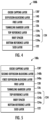
- a nonvolatile magnetoresistive tunnel-junction (MTJ) memory element 100a is illustrated as including a vertical stack of: (i) a seed layer 122, (ii) a magnetic reference layer (RL) 124 on the seed layer 122, (iii) a tunneling barrier layer 126 on the magnetic RL 124, and (iv) a magnetic free layer (FL) 128 on the tunneling barrier layer 126.
- the magnetic RL 124 is configured as a stacked composite of a bottom magnetic RL 124a, a Ruderman-Kittel-Kasuya-Yosida (RKKY) coupling/spacer layer 124b, and a top magnetic RL 124c on the spacer layer 124b.
- RKKY Ruderman-Kittel-Kasuya-Yosida
- the seed layer 122 may include a material selected from a group consisting of Ir, Ru, Ta, for example, and may have a thickness in a range from about 1 nm to about 200 nm.
- the bottom magnetic RL 124a may include a material selected from a group consisting of Co/Pt multilayers or Co-Pt alloys or another material including multilayers of magnetic materials such as Co or Fe with non-magnetic materials such as Pt or Pd, and may have a thickness in a range from about 1 nm to about 50 nm;
- the Ruderman-Kittel-Kasuya-Yosida (RKKY) coupling layer 124b may include a material selected from a group consisting of Ru, Rh, Ir and alloys thereof, and may have a thickness in a range from about 0.3 nm to about 1.8 nm; and the top magnetic RL 124c may include a material selected from a group consisting of Co/Pt multilayers
- the tunneling barrier layer 126 may be configured as a magnesium oxide (Mg-O) layer and/or a Mg-Al-O layer, for example, and have a thickness in a range from about 0.4 nm to about 2 nm.
- the magnetic FL 128 may include a material selected from a group consisting of Co, Fe, B, Nb, Ta, Mo, Si, Zr, Ge, W, and may have a thickness in a range from about 0.4 nm to about 5 nm.
- a diffusion-blocking layer (DBL) 140 is provided, which extends between (and forms interfaces with) the magnetic FL 128 and an oxide capping layer 130, as shown.
- the DBL 140 preferably has: (i) relatively high thermal stability (e.g., annealing stability), (ii) relatively high diffusion barrier energy (Eb) or relatively high segregation tendencies towards its layer interface(s), and (iii) reduced lattice mismatch vis-à-vis the adjacent magnetic FL 128 and the oxide capping layer 130.
- the annealing stability of the oxide capping layer 130 can be improved by configuring the DBL 140 such that, among other things, an increase in diffusion barrier energy (Eb) or relatively high segregation tendency, and a reduced lattice mismatch is achieved relative to a conventional interface between a magnetic FL and an oxide (e.g., Mg-O) capping layer (while maintaining sufficient perpendicular magnetic anisotropy (PMA) relative to the conventional interface).
- Eb diffusion barrier energy
- PMA perpendicular magnetic anisotropy
- the DBL 140 may have a thickness in a range from 0.1 nm to 1 nm, and includes at least one material selected from a group consisting of bismuth (Bi), antimony (Sb), osmium (Os), rhenium (Re), tin (Sn), rhodium (Rh), indium (In), and cadmium (Cd).
- osmium (Os), rhenium (Re) and rhodium (Rh) are believed to have a lower segregation tendency towards the free layer and oxide layer interfaces, but a relatively high diffusion barrier, which suggests that these elements may remain as deposited during post-annealing.
- bismuth (Bi), indium (In) and cadmium (Cd) are believed to have a lower diffusion barrier, but a higher segregation tendency towards the interfaces so diffusion during post-annealing is not likely to move these elements out of the interfaces.
- a first sub-group of bismuth (Bi), antimony (Sb), osmium (Os), rhenium (Re), and tin (Sn) may be chosen relative to a second sub-group of rhodium (Rh), indium (In), and cadmium (Cd), in some embodiments, based on a likelihood of stability (and other properties) of a subsequently formed oxide cap, which is described hereinbelow.
- a uniformity in the thickness of the DBL 140 may also be enhanced by cooling an intermediate-stage substrate containing the magnetic FL 128 to a temperature of about -250°C to about -100°C prior to deposition of the DBL 140.
- the oxide capping layer 130 of FIG. 3 which is provided on the DBL 140, may have a thickness in a range from 0.2 nm to 2 nm.
- an alternative oxide capping layer 130' may include at least one of strontium oxide (Sr-O), scandium oxide (Sc-O), beryllium oxide (Be-O), calcium oxide (Ca-O), tantalum oxide (Ta-O), yttrium oxide (Y-O), zirconium oxide (Zr-O), and hafnium oxide (Hf-O), which may provide lower formation energies and a high oxygen diffusion barrier.
- the DBL 140 of FIGS. 3-4 may be modified to include a stacked composite of a first DBL 140a of a first material, and a second DBL 140b of a second material, which extends between the first DBL 140a and the oxide capping layer 130'.
- MTJ magnetoresistive tunnel-junction
- This first material may be a material selected from a group consisting of magnesium (Mg), aluminum (Al), scandium (Sc), titanium (Ti), vanadium (V) and chromium (Cr), whereas the second material may include at least one of bismuth (Bi), antimony (Sb), osmium (Os), rhenium (Re), tin (Sn), rhodium (Rh), indium (In), and cadmium (Cd).
- the first DBL 140a may operate to suppress out-diffusion of atoms from the second DBL 140b into the magnetic FL 128 (e.g., during deposition and post-annealing of the second DBL 140b).
- the oxide capping layers 130, 130' of FIGS. 3-5 are modified to include a stacked composite of: (i) a first oxide layer 130a for superior annealing stability, which includes at least one oxide selected from a group consisting of scandium oxide (Sc-O), strontium oxide (Sr-O) and calcium oxide (Ca-O), and (ii) a second oxide layer 130b for good figure-of-merit (FOM), which includes at least one oxide selected from a group consisting of tantalum oxide (Ta-O) and hafnium oxide (Hf-O), and may be thicker than the first oxide layer 130a.
- a first oxide layer 130a for superior annealing stability which includes at least one oxide selected from a group consisting of scandium oxide (Sc-O), strontium oxide (Sr-O) and calcium oxide (Ca-O)
- a second oxide layer 130b for good figure-of-merit (FOM) which includes at least one oxide selected from a group consisting of tanta
- a spin-orbit torque magnetoresistive random access memory (SOT-MRAM) element 100e includes: (i) a magnetic reference layer 224 having a capping layer 250 thereon (e.g., nitride, such as Ta-N, Ti-N), (ii) a magnetic free layer 228, (iii) a tunneling barrier layer 226 extending between the magnetic reference layer 224 and the magnetic free layer 228, and (iv) a diffusion-blocking layer 240 on the magnetic free layer 228.
- a magnetic reference layer 224 having a capping layer 250 thereon (e.g., nitride, such as Ta-N, Ti-N)
- a magnetic free layer 228, iii) a tunneling barrier layer 226 extending between the magnetic reference layer 224 and the magnetic free layer 228, and (iv) a diffusion-blocking layer 240 on the magnetic free layer 228.
- the magnetic reference layer 224 is shown as including a stacked composite of a top reference layer 224a, a Ruderman-Kittel-Kasuya-Yosida (RKKY) coupling/spacer layer 224b, and a bottom reference layer 224c.
- RKKY Ruderman-Kittel-Kasuya-Yosida
- a bottom reference layer 224c may be configured as described hereinabove with respect to memory elements 100a-100d of FIGS. 3-6 .
- the SOT-MRAM element 100e of FIG. 7 further includes a thin shunt-current reducing oxide (SRO) layer 260, which extends between the diffusion-blocking layer 240 and a SOT write/read line 300, which may have a relatively high resistance and perform the same function as the strap layer 18 of the SOT-MRAM 20b of FIG. 1B during write and read operations.
- the SRO layer 260 is thin (to improve interfacial transparency) and provides a relatively high parallel resistance relative to the SOT write/read line 300, so that a lateral shunt current J c is blocked from passing laterally through the relatively low resistance free layer 228 during a write operation.
- the diffusion-blocking layer 240 also enhances the annealing stability of the thin SRO layer 260.
- the SRO layer may include at least one material selected from a group consisting of magnesium oxide (Mg-O), calcium oxide (Ca-O), scandium oxide (Sc-O), titanium oxide (Ti-O), vanadium oxide (V-O), iron oxide (Fe-O), nickel oxide (Ni-O), cobalt oxide (Co-O), zirconium oxide (Zr-O), niobium oxide (Nb-O), tantalum oxide (Ta-O), tungsten oxide (W-O), and osmium oxide (Os-O), and has a thickness in a range from about 0.2 nm to about 1 nm.
- Mg-O magnesium oxide
- Ca-O calcium oxide
- Sc-O scandium oxide
- Ti-O titanium oxide
- V-O vanadium oxide
- Fe-O iron oxide
- Ni-O nickel oxide
- cobalt oxide Co-O
- Zr-O zirconium oxide
- Nb-O tantalum oxide
- Ta-O tantalum
Landscapes
- Engineering & Computer Science (AREA)
- Manufacturing & Machinery (AREA)
- Computer Hardware Design (AREA)
- Mram Or Spin Memory Techniques (AREA)
- Hall/Mr Elements (AREA)
Applications Claiming Priority (2)
| Application Number | Priority Date | Filing Date | Title |
|---|---|---|---|
| US202163285672P | 2021-12-03 | 2021-12-03 | |
| US17/675,876 US12114578B2 (en) | 2021-12-03 | 2022-02-18 | Magnetoresistive memory elements for spin-transfer torque (STT) and spin-orbit torque (SOT) random access memories |
Publications (2)
| Publication Number | Publication Date |
|---|---|
| EP4192222A1 EP4192222A1 (en) | 2023-06-07 |
| EP4192222B1 true EP4192222B1 (en) | 2025-05-14 |
Family
ID=82899188
Family Applications (1)
| Application Number | Title | Priority Date | Filing Date |
|---|---|---|---|
| EP22189928.9A Active EP4192222B1 (en) | 2021-12-03 | 2022-08-11 | Magnetoresistive memory elements for spin-tranfer torque (stt) and spin-orbit torque (sot) random access memories |
Country Status (6)
| Country | Link |
|---|---|
| US (1) | US12114578B2 (https=) |
| EP (1) | EP4192222B1 (https=) |
| JP (1) | JP2023083208A (https=) |
| KR (1) | KR20230084003A (https=) |
| CN (1) | CN116234416A (https=) |
| TW (1) | TW202324800A (https=) |
Families Citing this family (2)
| Publication number | Priority date | Publication date | Assignee | Title |
|---|---|---|---|---|
| US20240164219A1 (en) * | 2022-11-11 | 2024-05-16 | International Business Machines Corporation | Fast switching mram having an aluminum-manganese-germanium free layer combined with a chromium diffusion barrier |
| US12573438B2 (en) | 2024-01-18 | 2026-03-10 | Taiwan Semiconductor Manufacturing Company, Ltd. | Device having rows of MRAM cells configured for concurrent writing and reading |
Citations (4)
| Publication number | Priority date | Publication date | Assignee | Title |
|---|---|---|---|---|
| US20130075839A1 (en) * | 2011-09-24 | 2013-03-28 | Taiwan Semiconductor Manufacturing Company, Ltd. | Structure and method for a mram device with an oxygen absorbing cap layer |
| US20140048893A1 (en) * | 2012-08-16 | 2014-02-20 | Taiwan Semiconductor Manufacturing Company, Ltd. | Magnetoresistive random access memory cell and fabricating the same |
| US20210159393A1 (en) * | 2019-11-26 | 2021-05-27 | Globalfoundries Singapore Pte. Ltd. | Magnetic tunnel junction devices and methods of forming thereof |
| US20210257541A1 (en) * | 2018-07-04 | 2021-08-19 | Sony Semiconductor Solutions Corporation | Magnetic tunnel junction element and semiconductor device |
Family Cites Families (10)
| Publication number | Priority date | Publication date | Assignee | Title |
|---|---|---|---|---|
| US7190557B2 (en) | 2004-04-14 | 2007-03-13 | Hitachi Global Storage Technologies Netherlands B.V. | Current-in-the-plane spin valve magnetoresistive sensor with dual metal oxide capping layers |
| US7770282B2 (en) | 2005-09-01 | 2010-08-10 | Hitachi Global Storage Technologies Netherlands B.V. | Method of making a magnetic sensing device having an insulator structure |
| JP5768498B2 (ja) | 2011-05-23 | 2015-08-26 | ソニー株式会社 | 記憶素子、記憶装置 |
| US9147833B2 (en) | 2013-07-05 | 2015-09-29 | Headway Technologies, Inc. | Hybridized oxide capping layer for perpendicular magnetic anisotropy |
| US9425387B1 (en) | 2015-09-08 | 2016-08-23 | Headway Technologies, Inc. | Magnetic element with perpendicular magnetic anisotropy for high coercivity after high temperature annealing |
| US10522744B2 (en) | 2017-10-10 | 2019-12-31 | Taiwan Semiconductor Manufacturing Company, Ltd. | High thermal stability by doping of oxide capping layer for spin torque transfer (STT) magnetic random access memory (MRAM) applications |
| US11165012B2 (en) | 2018-10-29 | 2021-11-02 | Taiwan Semiconductor Manufacturing Co., Ltd. | Magnetic device and magnetic random access memory |
| US11009570B2 (en) | 2018-11-16 | 2021-05-18 | Samsung Electronics Co., Ltd. | Hybrid oxide/metal cap layer for boron-free free layer |
| US11264566B2 (en) | 2019-06-21 | 2022-03-01 | Headway Technologies, Inc. | Magnetic element with perpendicular magnetic anisotropy (PMA) and improved coercivity field (Hc)/switching current ratio |
| US11264560B2 (en) | 2019-06-21 | 2022-03-01 | Headway Technologies, Inc. | Minimal thickness, low switching voltage magnetic free layers using an oxidation control layer and magnetic moment tuning layer for spintronic applications |
-
2022
- 2022-02-18 US US17/675,876 patent/US12114578B2/en active Active
- 2022-07-11 KR KR1020220085310A patent/KR20230084003A/ko active Pending
- 2022-08-11 EP EP22189928.9A patent/EP4192222B1/en active Active
- 2022-08-23 JP JP2022132440A patent/JP2023083208A/ja active Pending
- 2022-09-08 TW TW111134159A patent/TW202324800A/zh unknown
- 2022-12-01 CN CN202211531856.2A patent/CN116234416A/zh active Pending
Patent Citations (4)
| Publication number | Priority date | Publication date | Assignee | Title |
|---|---|---|---|---|
| US20130075839A1 (en) * | 2011-09-24 | 2013-03-28 | Taiwan Semiconductor Manufacturing Company, Ltd. | Structure and method for a mram device with an oxygen absorbing cap layer |
| US20140048893A1 (en) * | 2012-08-16 | 2014-02-20 | Taiwan Semiconductor Manufacturing Company, Ltd. | Magnetoresistive random access memory cell and fabricating the same |
| US20210257541A1 (en) * | 2018-07-04 | 2021-08-19 | Sony Semiconductor Solutions Corporation | Magnetic tunnel junction element and semiconductor device |
| US20210159393A1 (en) * | 2019-11-26 | 2021-05-27 | Globalfoundries Singapore Pte. Ltd. | Magnetic tunnel junction devices and methods of forming thereof |
Also Published As
| Publication number | Publication date |
|---|---|
| US12114578B2 (en) | 2024-10-08 |
| JP2023083208A (ja) | 2023-06-15 |
| EP4192222A1 (en) | 2023-06-07 |
| KR20230084003A (ko) | 2023-06-12 |
| CN116234416A (zh) | 2023-06-06 |
| TW202324800A (zh) | 2023-06-16 |
| US20230180627A1 (en) | 2023-06-08 |
Similar Documents
| Publication | Publication Date | Title |
|---|---|---|
| US9608040B2 (en) | Memory device and method of fabricating the same | |
| US10418548B2 (en) | Magnetic memory device | |
| US11127445B2 (en) | Magnetic device | |
| JP6202764B2 (ja) | 垂直磁気異方性の強化のための二重MgO界面およびCoFeB層を有する垂直スピントランスファートルク(STT)メモリセル | |
| CN104051610B (zh) | 具有插入层的磁性结和使用该磁性结的磁存储器 | |
| US8492169B2 (en) | Magnetic tunnel junction for MRAM applications | |
| CN102473450B (zh) | 具有带垂直磁化取向的基准层的磁性叠层 | |
| US8704319B2 (en) | Method and system for providing magnetic layers having insertion layers for use in spin transfer torque memories | |
| US11217289B1 (en) | Spinel containing magnetic tunnel junction and method of making the same | |
| EP4192222B1 (en) | Magnetoresistive memory elements for spin-tranfer torque (stt) and spin-orbit torque (sot) random access memories | |
| TW201435869A (zh) | 提供具有梯度磁性自由層之磁性接面的方法與系統 | |
| US11176981B1 (en) | Spinel containing magnetic tunnel junction and method of making the same | |
| KR20160031614A (ko) | 자기 기억 소자 및 이의 제조 방법 | |
| EP3867959B1 (en) | Magnetoresistive devices and methods therefor | |
| US10431627B2 (en) | Magnetic memory devices and methods for manufacturing the same | |
| US11443790B2 (en) | Spinel containing magnetic tunnel junction and method of making the same | |
| CN109427962B (zh) | 磁性结及提供所述磁性结的方法和磁性存储器 | |
| US20240349622A1 (en) | Templating layers for growth of perpendicularly magnetized heusler films | |
| US12457906B2 (en) | Spin-orbit torque magnetic random-access memory (SOT-MRAM) device | |
| US20250301917A1 (en) | Magnetic memory device and method of manufacturing the same | |
| KR20220066725A (ko) | 자기 메모리 소자 | |
| US20230276714A1 (en) | Semiconductor device and method of making the same | |
| CN107452868B (zh) | 一种垂直型磁电阻元件及其制造工艺 | |
| WO2023063198A1 (ja) | 記憶素子及び記憶装置 |
Legal Events
| Date | Code | Title | Description |
|---|---|---|---|
| PUAI | Public reference made under article 153(3) epc to a published international application that has entered the european phase |
Free format text: ORIGINAL CODE: 0009012 |
|
| STAA | Information on the status of an ep patent application or granted ep patent |
Free format text: STATUS: REQUEST FOR EXAMINATION WAS MADE |
|
| 17P | Request for examination filed |
Effective date: 20230328 |
|
| AK | Designated contracting states |
Kind code of ref document: A1 Designated state(s): AL AT BE BG CH CY CZ DE DK EE ES FI FR GB GR HR HU IE IS IT LI LT LU LV MC MK MT NL NO PL PT RO RS SE SI SK SM TR |
|
| STAA | Information on the status of an ep patent application or granted ep patent |
Free format text: STATUS: EXAMINATION IS IN PROGRESS |
|
| 17Q | First examination report despatched |
Effective date: 20230705 |
|
| RIC1 | Information provided on ipc code assigned before grant |
Ipc: H10N 50/80 20230101ALN20240623BHEP Ipc: H10N 50/85 20230101ALI20240623BHEP Ipc: H10N 50/10 20230101AFI20240623BHEP |
|
| RIC1 | Information provided on ipc code assigned before grant |
Ipc: H10N 50/80 20230101ALN20241205BHEP Ipc: H10N 50/85 20230101ALI20241205BHEP Ipc: H10N 50/10 20230101AFI20241205BHEP |
|
| RIC1 | Information provided on ipc code assigned before grant |
Ipc: H10N 50/80 20230101ALN20241213BHEP Ipc: H10N 50/85 20230101ALI20241213BHEP Ipc: H10N 50/10 20230101AFI20241213BHEP |
|
| GRAP | Despatch of communication of intention to grant a patent |
Free format text: ORIGINAL CODE: EPIDOSNIGR1 |
|
| STAA | Information on the status of an ep patent application or granted ep patent |
Free format text: STATUS: GRANT OF PATENT IS INTENDED |
|
| INTG | Intention to grant announced |
Effective date: 20250205 |
|
| GRAS | Grant fee paid |
Free format text: ORIGINAL CODE: EPIDOSNIGR3 |
|
| GRAA | (expected) grant |
Free format text: ORIGINAL CODE: 0009210 |
|
| STAA | Information on the status of an ep patent application or granted ep patent |
Free format text: STATUS: THE PATENT HAS BEEN GRANTED |
|
| AK | Designated contracting states |
Kind code of ref document: B1 Designated state(s): AL AT BE BG CH CY CZ DE DK EE ES FI FR GB GR HR HU IE IS IT LI LT LU LV MC MK MT NL NO PL PT RO RS SE SI SK SM TR |
|
| REG | Reference to a national code |
Ref country code: GB Ref legal event code: FG4D |
|
| REG | Reference to a national code |
Ref country code: CH Ref legal event code: EP |
|
| REG | Reference to a national code |
Ref country code: IE Ref legal event code: FG4D |
|
| REG | Reference to a national code |
Ref country code: DE Ref legal event code: R096 Ref document number: 602022014558 Country of ref document: DE |
|
| PGFP | Annual fee paid to national office [announced via postgrant information from national office to epo] |
Ref country code: NL Payment date: 20250716 Year of fee payment: 4 |
|
| REG | Reference to a national code |
Ref country code: NL Ref legal event code: FP |
|
| PG25 | Lapsed in a contracting state [announced via postgrant information from national office to epo] |
Ref country code: ES Free format text: LAPSE BECAUSE OF FAILURE TO SUBMIT A TRANSLATION OF THE DESCRIPTION OR TO PAY THE FEE WITHIN THE PRESCRIBED TIME-LIMIT Effective date: 20250514 Ref country code: PT Free format text: LAPSE BECAUSE OF FAILURE TO SUBMIT A TRANSLATION OF THE DESCRIPTION OR TO PAY THE FEE WITHIN THE PRESCRIBED TIME-LIMIT Effective date: 20250915 Ref country code: FI Free format text: LAPSE BECAUSE OF FAILURE TO SUBMIT A TRANSLATION OF THE DESCRIPTION OR TO PAY THE FEE WITHIN THE PRESCRIBED TIME-LIMIT Effective date: 20250514 |
|
| PGFP | Annual fee paid to national office [announced via postgrant information from national office to epo] |
Ref country code: DE Payment date: 20250708 Year of fee payment: 4 |
|
| REG | Reference to a national code |
Ref country code: LT Ref legal event code: MG9D |
|
| PG25 | Lapsed in a contracting state [announced via postgrant information from national office to epo] |
Ref country code: GR Free format text: LAPSE BECAUSE OF FAILURE TO SUBMIT A TRANSLATION OF THE DESCRIPTION OR TO PAY THE FEE WITHIN THE PRESCRIBED TIME-LIMIT Effective date: 20250815 Ref country code: NO Free format text: LAPSE BECAUSE OF FAILURE TO SUBMIT A TRANSLATION OF THE DESCRIPTION OR TO PAY THE FEE WITHIN THE PRESCRIBED TIME-LIMIT Effective date: 20250814 |
|
| PG25 | Lapsed in a contracting state [announced via postgrant information from national office to epo] |
Ref country code: PL Free format text: LAPSE BECAUSE OF FAILURE TO SUBMIT A TRANSLATION OF THE DESCRIPTION OR TO PAY THE FEE WITHIN THE PRESCRIBED TIME-LIMIT Effective date: 20250514 |
|
| REG | Reference to a national code |
Ref country code: AT Ref legal event code: MK05 Ref document number: 1795935 Country of ref document: AT Kind code of ref document: T Effective date: 20250514 |
|
| PG25 | Lapsed in a contracting state [announced via postgrant information from national office to epo] |
Ref country code: BG Free format text: LAPSE BECAUSE OF FAILURE TO SUBMIT A TRANSLATION OF THE DESCRIPTION OR TO PAY THE FEE WITHIN THE PRESCRIBED TIME-LIMIT Effective date: 20250514 |
|
| PG25 | Lapsed in a contracting state [announced via postgrant information from national office to epo] |
Ref country code: HR Free format text: LAPSE BECAUSE OF FAILURE TO SUBMIT A TRANSLATION OF THE DESCRIPTION OR TO PAY THE FEE WITHIN THE PRESCRIBED TIME-LIMIT Effective date: 20250514 |
|
| PG25 | Lapsed in a contracting state [announced via postgrant information from national office to epo] |
Ref country code: AT Free format text: LAPSE BECAUSE OF FAILURE TO SUBMIT A TRANSLATION OF THE DESCRIPTION OR TO PAY THE FEE WITHIN THE PRESCRIBED TIME-LIMIT Effective date: 20250514 |
|
| PG25 | Lapsed in a contracting state [announced via postgrant information from national office to epo] |
Ref country code: RS Free format text: LAPSE BECAUSE OF FAILURE TO SUBMIT A TRANSLATION OF THE DESCRIPTION OR TO PAY THE FEE WITHIN THE PRESCRIBED TIME-LIMIT Effective date: 20250814 |
|
| PG25 | Lapsed in a contracting state [announced via postgrant information from national office to epo] |
Ref country code: IS Free format text: LAPSE BECAUSE OF FAILURE TO SUBMIT A TRANSLATION OF THE DESCRIPTION OR TO PAY THE FEE WITHIN THE PRESCRIBED TIME-LIMIT Effective date: 20250914 |
|
| PG25 | Lapsed in a contracting state [announced via postgrant information from national office to epo] |
Ref country code: LV Free format text: LAPSE BECAUSE OF FAILURE TO SUBMIT A TRANSLATION OF THE DESCRIPTION OR TO PAY THE FEE WITHIN THE PRESCRIBED TIME-LIMIT Effective date: 20250514 |
|
| P01 | Opt-out of the competence of the unified patent court (upc) registered |
Free format text: CASE NUMBER: UPC_APP_0013987_4192222/2025 Effective date: 20251119 |
|
| PG25 | Lapsed in a contracting state [announced via postgrant information from national office to epo] |
Ref country code: SM Free format text: LAPSE BECAUSE OF FAILURE TO SUBMIT A TRANSLATION OF THE DESCRIPTION OR TO PAY THE FEE WITHIN THE PRESCRIBED TIME-LIMIT Effective date: 20250514 Ref country code: DK Free format text: LAPSE BECAUSE OF FAILURE TO SUBMIT A TRANSLATION OF THE DESCRIPTION OR TO PAY THE FEE WITHIN THE PRESCRIBED TIME-LIMIT Effective date: 20250514 |
|
| PG25 | Lapsed in a contracting state [announced via postgrant information from national office to epo] |
Ref country code: CZ Free format text: LAPSE BECAUSE OF FAILURE TO SUBMIT A TRANSLATION OF THE DESCRIPTION OR TO PAY THE FEE WITHIN THE PRESCRIBED TIME-LIMIT Effective date: 20250514 |
|
| PG25 | Lapsed in a contracting state [announced via postgrant information from national office to epo] |
Ref country code: EE Free format text: LAPSE BECAUSE OF FAILURE TO SUBMIT A TRANSLATION OF THE DESCRIPTION OR TO PAY THE FEE WITHIN THE PRESCRIBED TIME-LIMIT Effective date: 20250514 |
|
| PG25 | Lapsed in a contracting state [announced via postgrant information from national office to epo] |
Ref country code: SK Free format text: LAPSE BECAUSE OF FAILURE TO SUBMIT A TRANSLATION OF THE DESCRIPTION OR TO PAY THE FEE WITHIN THE PRESCRIBED TIME-LIMIT Effective date: 20250514 |
|
| PG25 | Lapsed in a contracting state [announced via postgrant information from national office to epo] |
Ref country code: IT Free format text: LAPSE BECAUSE OF FAILURE TO SUBMIT A TRANSLATION OF THE DESCRIPTION OR TO PAY THE FEE WITHIN THE PRESCRIBED TIME-LIMIT Effective date: 20250514 |
|
| REG | Reference to a national code |
Ref country code: DE Ref legal event code: R097 Ref document number: 602022014558 Country of ref document: DE |
|
| PG25 | Lapsed in a contracting state [announced via postgrant information from national office to epo] |
Ref country code: RO Free format text: LAPSE BECAUSE OF FAILURE TO SUBMIT A TRANSLATION OF THE DESCRIPTION OR TO PAY THE FEE WITHIN THE PRESCRIBED TIME-LIMIT Effective date: 20250514 |
|
| PLBE | No opposition filed within time limit |
Free format text: ORIGINAL CODE: 0009261 |
|
| STAA | Information on the status of an ep patent application or granted ep patent |
Free format text: STATUS: NO OPPOSITION FILED WITHIN TIME LIMIT |
|
| REG | Reference to a national code |
Ref country code: CH Ref legal event code: H13 Free format text: ST27 STATUS EVENT CODE: U-0-0-H10-H13 (AS PROVIDED BY THE NATIONAL OFFICE) Effective date: 20260324 |
|
| REG | Reference to a national code |
Ref country code: CH Ref legal event code: L10 Free format text: ST27 STATUS EVENT CODE: U-0-0-L10-L00 (AS PROVIDED BY THE NATIONAL OFFICE) Effective date: 20260325 |
|
| PG25 | Lapsed in a contracting state [announced via postgrant information from national office to epo] |
Ref country code: MC Free format text: LAPSE BECAUSE OF FAILURE TO SUBMIT A TRANSLATION OF THE DESCRIPTION OR TO PAY THE FEE WITHIN THE PRESCRIBED TIME-LIMIT Effective date: 20250514 |
|
| PG25 | Lapsed in a contracting state [announced via postgrant information from national office to epo] |
Ref country code: LU Free format text: LAPSE BECAUSE OF NON-PAYMENT OF DUE FEES Effective date: 20250811 |
|
| 26N | No opposition filed |
Effective date: 20260217 |