EP4191117A1 - Vorrichtung - Google Patents
Vorrichtung Download PDFInfo
- Publication number
- EP4191117A1 EP4191117A1 EP22208273.7A EP22208273A EP4191117A1 EP 4191117 A1 EP4191117 A1 EP 4191117A1 EP 22208273 A EP22208273 A EP 22208273A EP 4191117 A1 EP4191117 A1 EP 4191117A1
- Authority
- EP
- European Patent Office
- Prior art keywords
- tank
- counterpart
- connection system
- connection
- tank wall
- Prior art date
- Legal status (The legal status is an assumption and is not a legal conclusion. Google has not performed a legal analysis and makes no representation as to the accuracy of the status listed.)
- Granted
Links
Images
Classifications
-
- F—MECHANICAL ENGINEERING; LIGHTING; HEATING; WEAPONS; BLASTING
- F17—STORING OR DISTRIBUTING GASES OR LIQUIDS
- F17C—VESSELS FOR CONTAINING OR STORING COMPRESSED, LIQUEFIED OR SOLIDIFIED GASES; FIXED-CAPACITY GAS-HOLDERS; FILLING VESSELS WITH, OR DISCHARGING FROM VESSELS, COMPRESSED, LIQUEFIED, OR SOLIDIFIED GASES
- F17C3/00—Vessels not under pressure
-
- F—MECHANICAL ENGINEERING; LIGHTING; HEATING; WEAPONS; BLASTING
- F16—ENGINEERING ELEMENTS AND UNITS; GENERAL MEASURES FOR PRODUCING AND MAINTAINING EFFECTIVE FUNCTIONING OF MACHINES OR INSTALLATIONS; THERMAL INSULATION IN GENERAL
- F16L—PIPES; JOINTS OR FITTINGS FOR PIPES; SUPPORTS FOR PIPES, CABLES OR PROTECTIVE TUBING; MEANS FOR THERMAL INSULATION IN GENERAL
- F16L23/00—Flanged joints
- F16L23/16—Flanged joints characterised by the sealing means
- F16L23/24—Flanged joints characterised by the sealing means specially adapted for unequal expansion of the parts of the joint
-
- F—MECHANICAL ENGINEERING; LIGHTING; HEATING; WEAPONS; BLASTING
- F16—ENGINEERING ELEMENTS AND UNITS; GENERAL MEASURES FOR PRODUCING AND MAINTAINING EFFECTIVE FUNCTIONING OF MACHINES OR INSTALLATIONS; THERMAL INSULATION IN GENERAL
- F16L—PIPES; JOINTS OR FITTINGS FOR PIPES; SUPPORTS FOR PIPES, CABLES OR PROTECTIVE TUBING; MEANS FOR THERMAL INSULATION IN GENERAL
- F16L23/00—Flanged joints
- F16L23/02—Flanged joints the flanges being connected by members tensioned axially
- F16L23/032—Flanged joints the flanges being connected by members tensioned axially characterised by the shape or composition of the flanges
-
- F—MECHANICAL ENGINEERING; LIGHTING; HEATING; WEAPONS; BLASTING
- F16—ENGINEERING ELEMENTS AND UNITS; GENERAL MEASURES FOR PRODUCING AND MAINTAINING EFFECTIVE FUNCTIONING OF MACHINES OR INSTALLATIONS; THERMAL INSULATION IN GENERAL
- F16L—PIPES; JOINTS OR FITTINGS FOR PIPES; SUPPORTS FOR PIPES, CABLES OR PROTECTIVE TUBING; MEANS FOR THERMAL INSULATION IN GENERAL
- F16L51/00—Expansion-compensation arrangements for pipe-lines
-
- F—MECHANICAL ENGINEERING; LIGHTING; HEATING; WEAPONS; BLASTING
- F17—STORING OR DISTRIBUTING GASES OR LIQUIDS
- F17C—VESSELS FOR CONTAINING OR STORING COMPRESSED, LIQUEFIED OR SOLIDIFIED GASES; FIXED-CAPACITY GAS-HOLDERS; FILLING VESSELS WITH, OR DISCHARGING FROM VESSELS, COMPRESSED, LIQUEFIED, OR SOLIDIFIED GASES
- F17C13/00—Details of vessels or of the filling or discharging of vessels
- F17C13/04—Arrangement or mounting of valves
-
- F—MECHANICAL ENGINEERING; LIGHTING; HEATING; WEAPONS; BLASTING
- F16—ENGINEERING ELEMENTS AND UNITS; GENERAL MEASURES FOR PRODUCING AND MAINTAINING EFFECTIVE FUNCTIONING OF MACHINES OR INSTALLATIONS; THERMAL INSULATION IN GENERAL
- F16B—DEVICES FOR FASTENING OR SECURING CONSTRUCTIONAL ELEMENTS OR MACHINE PARTS TOGETHER, e.g. NAILS, BOLTS, CIRCLIPS, CLAMPS, CLIPS OR WEDGES; JOINTS OR JOINTING
- F16B5/00—Joining sheets or plates, e.g. panels, to one another or to strips or bars parallel to them
- F16B5/02—Joining sheets or plates, e.g. panels, to one another or to strips or bars parallel to them by means of fastening members using screw-thread
- F16B5/0241—Joining sheets or plates, e.g. panels, to one another or to strips or bars parallel to them by means of fastening members using screw-thread with the possibility for the connection to absorb deformation, e.g. thermal or vibrational
-
- F—MECHANICAL ENGINEERING; LIGHTING; HEATING; WEAPONS; BLASTING
- F17—STORING OR DISTRIBUTING GASES OR LIQUIDS
- F17C—VESSELS FOR CONTAINING OR STORING COMPRESSED, LIQUEFIED OR SOLIDIFIED GASES; FIXED-CAPACITY GAS-HOLDERS; FILLING VESSELS WITH, OR DISCHARGING FROM VESSELS, COMPRESSED, LIQUEFIED, OR SOLIDIFIED GASES
- F17C2203/00—Vessel construction, in particular walls or details thereof
- F17C2203/01—Reinforcing or suspension means
- F17C2203/011—Reinforcing means
- F17C2203/012—Reinforcing means on or in the wall, e.g. ribs
-
- F—MECHANICAL ENGINEERING; LIGHTING; HEATING; WEAPONS; BLASTING
- F17—STORING OR DISTRIBUTING GASES OR LIQUIDS
- F17C—VESSELS FOR CONTAINING OR STORING COMPRESSED, LIQUEFIED OR SOLIDIFIED GASES; FIXED-CAPACITY GAS-HOLDERS; FILLING VESSELS WITH, OR DISCHARGING FROM VESSELS, COMPRESSED, LIQUEFIED, OR SOLIDIFIED GASES
- F17C2203/00—Vessel construction, in particular walls or details thereof
- F17C2203/06—Materials for walls or layers thereof; Properties or structures of walls or their materials
- F17C2203/0602—Wall structures; Special features thereof
- F17C2203/0612—Wall structures
- F17C2203/0614—Single wall
- F17C2203/0617—Single wall with one layer
-
- F—MECHANICAL ENGINEERING; LIGHTING; HEATING; WEAPONS; BLASTING
- F17—STORING OR DISTRIBUTING GASES OR LIQUIDS
- F17C—VESSELS FOR CONTAINING OR STORING COMPRESSED, LIQUEFIED OR SOLIDIFIED GASES; FIXED-CAPACITY GAS-HOLDERS; FILLING VESSELS WITH, OR DISCHARGING FROM VESSELS, COMPRESSED, LIQUEFIED, OR SOLIDIFIED GASES
- F17C2203/00—Vessel construction, in particular walls or details thereof
- F17C2203/06—Materials for walls or layers thereof; Properties or structures of walls or their materials
- F17C2203/0634—Materials for walls or layers thereof
- F17C2203/0658—Synthetics
- F17C2203/0663—Synthetics in form of fibers or filaments
-
- F—MECHANICAL ENGINEERING; LIGHTING; HEATING; WEAPONS; BLASTING
- F17—STORING OR DISTRIBUTING GASES OR LIQUIDS
- F17C—VESSELS FOR CONTAINING OR STORING COMPRESSED, LIQUEFIED OR SOLIDIFIED GASES; FIXED-CAPACITY GAS-HOLDERS; FILLING VESSELS WITH, OR DISCHARGING FROM VESSELS, COMPRESSED, LIQUEFIED, OR SOLIDIFIED GASES
- F17C2205/00—Vessel construction, in particular mounting arrangements, attachments or identifications means
- F17C2205/03—Fluid connections, filters, valves, closure means or other attachments
- F17C2205/0302—Fittings, valves, filters, or components in connection with the gas storage device
-
- F—MECHANICAL ENGINEERING; LIGHTING; HEATING; WEAPONS; BLASTING
- F17—STORING OR DISTRIBUTING GASES OR LIQUIDS
- F17C—VESSELS FOR CONTAINING OR STORING COMPRESSED, LIQUEFIED OR SOLIDIFIED GASES; FIXED-CAPACITY GAS-HOLDERS; FILLING VESSELS WITH, OR DISCHARGING FROM VESSELS, COMPRESSED, LIQUEFIED, OR SOLIDIFIED GASES
- F17C2205/00—Vessel construction, in particular mounting arrangements, attachments or identifications means
- F17C2205/03—Fluid connections, filters, valves, closure means or other attachments
- F17C2205/0302—Fittings, valves, filters, or components in connection with the gas storage device
- F17C2205/0305—Bosses, e.g. boss collars
-
- F—MECHANICAL ENGINEERING; LIGHTING; HEATING; WEAPONS; BLASTING
- F17—STORING OR DISTRIBUTING GASES OR LIQUIDS
- F17C—VESSELS FOR CONTAINING OR STORING COMPRESSED, LIQUEFIED OR SOLIDIFIED GASES; FIXED-CAPACITY GAS-HOLDERS; FILLING VESSELS WITH, OR DISCHARGING FROM VESSELS, COMPRESSED, LIQUEFIED, OR SOLIDIFIED GASES
- F17C2209/00—Vessel construction, in particular methods of manufacturing
- F17C2209/22—Assembling processes
- F17C2209/228—Assembling processes by screws, bolts or rivets
-
- F—MECHANICAL ENGINEERING; LIGHTING; HEATING; WEAPONS; BLASTING
- F17—STORING OR DISTRIBUTING GASES OR LIQUIDS
- F17C—VESSELS FOR CONTAINING OR STORING COMPRESSED, LIQUEFIED OR SOLIDIFIED GASES; FIXED-CAPACITY GAS-HOLDERS; FILLING VESSELS WITH, OR DISCHARGING FROM VESSELS, COMPRESSED, LIQUEFIED, OR SOLIDIFIED GASES
- F17C2221/00—Handled fluid, in particular type of fluid
- F17C2221/01—Pure fluids
- F17C2221/011—Oxygen
-
- F—MECHANICAL ENGINEERING; LIGHTING; HEATING; WEAPONS; BLASTING
- F17—STORING OR DISTRIBUTING GASES OR LIQUIDS
- F17C—VESSELS FOR CONTAINING OR STORING COMPRESSED, LIQUEFIED OR SOLIDIFIED GASES; FIXED-CAPACITY GAS-HOLDERS; FILLING VESSELS WITH, OR DISCHARGING FROM VESSELS, COMPRESSED, LIQUEFIED, OR SOLIDIFIED GASES
- F17C2221/00—Handled fluid, in particular type of fluid
- F17C2221/01—Pure fluids
- F17C2221/012—Hydrogen
-
- F—MECHANICAL ENGINEERING; LIGHTING; HEATING; WEAPONS; BLASTING
- F17—STORING OR DISTRIBUTING GASES OR LIQUIDS
- F17C—VESSELS FOR CONTAINING OR STORING COMPRESSED, LIQUEFIED OR SOLIDIFIED GASES; FIXED-CAPACITY GAS-HOLDERS; FILLING VESSELS WITH, OR DISCHARGING FROM VESSELS, COMPRESSED, LIQUEFIED, OR SOLIDIFIED GASES
- F17C2223/00—Handled fluid before transfer, i.e. state of fluid when stored in the vessel or before transfer from the vessel
- F17C2223/01—Handled fluid before transfer, i.e. state of fluid when stored in the vessel or before transfer from the vessel characterised by the phase
- F17C2223/0146—Two-phase
- F17C2223/0153—Liquefied gas, e.g. LPG, GPL
- F17C2223/0161—Liquefied gas, e.g. LPG, GPL cryogenic, e.g. LNG, GNL, PLNG
-
- F—MECHANICAL ENGINEERING; LIGHTING; HEATING; WEAPONS; BLASTING
- F17—STORING OR DISTRIBUTING GASES OR LIQUIDS
- F17C—VESSELS FOR CONTAINING OR STORING COMPRESSED, LIQUEFIED OR SOLIDIFIED GASES; FIXED-CAPACITY GAS-HOLDERS; FILLING VESSELS WITH, OR DISCHARGING FROM VESSELS, COMPRESSED, LIQUEFIED, OR SOLIDIFIED GASES
- F17C2223/00—Handled fluid before transfer, i.e. state of fluid when stored in the vessel or before transfer from the vessel
- F17C2223/03—Handled fluid before transfer, i.e. state of fluid when stored in the vessel or before transfer from the vessel characterised by the pressure level
- F17C2223/033—Small pressure, e.g. for liquefied gas
-
- F—MECHANICAL ENGINEERING; LIGHTING; HEATING; WEAPONS; BLASTING
- F17—STORING OR DISTRIBUTING GASES OR LIQUIDS
- F17C—VESSELS FOR CONTAINING OR STORING COMPRESSED, LIQUEFIED OR SOLIDIFIED GASES; FIXED-CAPACITY GAS-HOLDERS; FILLING VESSELS WITH, OR DISCHARGING FROM VESSELS, COMPRESSED, LIQUEFIED, OR SOLIDIFIED GASES
- F17C2270/00—Applications
- F17C2270/01—Applications for fluid transport or storage
- F17C2270/0186—Applications for fluid transport or storage in the air or in space
- F17C2270/0197—Rockets
-
- Y—GENERAL TAGGING OF NEW TECHNOLOGICAL DEVELOPMENTS; GENERAL TAGGING OF CROSS-SECTIONAL TECHNOLOGIES SPANNING OVER SEVERAL SECTIONS OF THE IPC; TECHNICAL SUBJECTS COVERED BY FORMER USPC CROSS-REFERENCE ART COLLECTIONS [XRACs] AND DIGESTS
- Y02—TECHNOLOGIES OR APPLICATIONS FOR MITIGATION OR ADAPTATION AGAINST CLIMATE CHANGE
- Y02E—REDUCTION OF GREENHOUSE GAS [GHG] EMISSIONS, RELATED TO ENERGY GENERATION, TRANSMISSION OR DISTRIBUTION
- Y02E60/00—Enabling technologies; Technologies with a potential or indirect contribution to GHG emissions mitigation
- Y02E60/30—Hydrogen technology
- Y02E60/32—Hydrogen storage
Definitions
- the invention relates to a connection system for a cryogenic tank, the tank wall of which is formed from a first material, the connection system having a connection piece for a component to be connected to the tank, and the connection piece being formed from a second material and the connection piece on a tank outside and is positioned substantially congruently with a passage opening of the tank wall, and wherein at least one sealing element is provided, and the first and the second material have different coefficients of thermal expansion.
- carrier rockets use liquid, i.e. extremely cold (cryogenic) hydrogen (LH2 at 20 K - 253.15 °C) and oxygen (LOX at 90 K or -183.15 °C) as fuel.
- liquid i.e. extremely cold (cryogenic) hydrogen (LH2 at 20 K - 253.15 °C) and oxygen (LOX at 90 K or -183.15 °C)
- LH2 extremely cold (cryogenic) hydrogen
- LOX oxygen
- CFRP carbon fiber reinforced plastics
- the object of the invention is to specify a connection system for a cryogenic tank in which, due to unequal coefficients of thermal expansion of the materials combined with one another, thermally induced mechanical stresses do not lead to radial loading of connecting elements.
- a counterpart formed with the second material is mounted on the inside of the tank is positioned, which can be connected to the connection piece with the aid of at least two fastening elements, in such a way that the tank wall is clamped between the counterpart, the connection piece and the at least one sealing element and, to compensate for thermally induced mechanical stresses, the connection piece and the counterpart can be slightly displaced remains parallel to the tank wall.
- connection piece and counterpart are made of the same material, thermally induced mechanical stresses within the connection system are reduced at low (cryogenic) temperatures of the same or lower than around -183 °C in the tank and comparatively high outside temperatures of around 20 °C, since the cold-related radial Shrinkage of the connecting piece and the counterpart are approximately the same.
- counterpart lying on the side of the tank there is a larger-area introduction of force of any forces introduced from the connecting piece into the tank wall.
- the connecting piece is essentially sleeve-like and has a peripheral fastening flange on a first end facing the outside of the tank and a connecting flange for the component on a second end pointing away therefrom.
- a standard component can be used as a connecting piece.
- the at least two fastening elements are designed as threaded bolts.
- the counterpart is preferably designed essentially in the form of a circular ring. This results in a force application that is uniform around the circumference guaranteed.
- connection piece, the counterpart and the at least one sealing element are designed to be essentially rotationally symmetrical to a longitudinal central axis.
- connection piece, the counterpart and the sealing element each have a preferably circular opening which, when the connection system is installed, is preferably positioned congruently to one another and congruently with the through-opening in the tank wall at a room temperature of around 20°C.
- the fastening flange preferably has a number of preferably non-continuous threaded bores corresponding to the number of threaded bolts and the counterpart has a corresponding number of unthreaded through bores for the threaded bolts or vice versa.
- one sealing element is sufficient due to the provision of non-continuous threaded bores or blind bores with a thread.
- the component provided with the non-continuous threaded bores has non-threaded through bores configured congruently to these.
- the at least one sealing element is positioned between the outside of the tank and the fastening flange and/or between the counterpart and the inside of the tank. This gives greater flexibility during assembly.
- the threaded bolts are screwed in from an interior of the tank or starting from the outside of the tank. Appropriate access to the interior of the tank is required.
- the first material is a fiber composite plastic, such as a glass fiber reinforced or a carbon fiber reinforced plastic.
- a tank that is lighter than an aluminum tank can be realized.
- the second material is preferably formed from a metal such as aluminum, titanium, stainless steel or a metal alloy. This enables a mechanically robust connection of components to the tank, such as lines, pipelines, sensors or the like.
- the at least one sealing element is formed from a plastic such as polytetrafluoroethylene (PTFE). Due to the soft plastic, damage to the tank wall by the metal parts clamped to it is avoided and at the same time a reliable sealing effect is achieved.
- PTFE polytetrafluoroethylene
- the at least one sealing element is preferably designed as an essentially annular flat seal or as a spring-loaded seal.
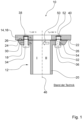
- the figure 1 shows a schematic longitudinal section through a connection system according to the prior art, the connection system in the left half of the drawing I being at a temperature T 1 of about 20° (room temperature), whereas the connection system in the right half of the drawing II being at a cryogenic temperature of is less than or equal to -183.15 °C (boiling temperature of oxygen).
- a connection system 10 includes, among other things, a connecting piece 12 for a component that is not shown here and is to be connected to a tank wall 14 of a tank 16 that is not shown in detail.
- the connecting piece 12 has an annular flange 18 , which serves to rest against the tank wall 14 and continues into a tubular connecting section 20 directed away from the tank wall 14 .
- a sealing element 26 is preferably provided between an outer side 22 of the tank wall 14 and a sealing surface 24 of the flange 18 .
- the tank wall 14 is made of a fiber composite plastic such as a carbon fiber reinforced plastic, while the connecting piece 12 is made of a metallic material such as steel, titanium or aluminum.
- the flange 18 has a multiplicity of through-holes which are arranged at a uniform distance from one another on the circumferential side, of which only two through-holes 30, 32 are shown here as a representative of all the others.
- the flange 16 is fastened to the tank wall 14 with the aid of a number of threaded bolts corresponding to the number of through-holes, which are each screwed into an assigned threaded insert on the tank wall side, with the threaded inserts introduced starting from the outside 22 of the tank 16 not penetrating the tank wall 14 .
- only two threaded bolts 34, 36 and two threaded inserts 38, 40 are shown in the drawing as representative of all others.
- connection system 10 is constructed rotationally symmetrically to a longitudinal central axis 46 .
- the connection system 10 is at room temperature or a temperature T 1 of approximately 20° C., whereas the connection system 10 is at a cryogenic temperature of equal to or less than -183.15° C. in a second half of the drawing II .
- a material formed with a carbon-reinforced plastic or material has a coefficient of thermal expansion ⁇ 1 of about 0.2 ⁇ 10 -6 K -1 in the direction of the fibers and of 30 ⁇ 10 -6 K -1 perpendicular to the direction of the fibers, while the coefficient of thermal expansion ⁇ 2 for a material such as steel in all spatial directions is about 12 ⁇ 10 -6 K -1 to 15 ⁇ 10 -6 K -1 and for aluminum about 23 ⁇ 10 -6 K -1 .
- connection system 10 Due to these temperature-related shrinkage effects of the connection system 10 outlined above, there are undesired mechanical stresses between the tank wall 14 and the connection piece 12 of the connection system 10, which in the connection system according to the invention (cf 2 ) should be avoided as far as possible.
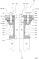
- the figure 2 illustrates a schematic longitudinal section of a connection system according to the invention, the connection system in the left half of the drawing III being at a temperature T 1 of about 20° (room temperature), whereas the connection system in the right half of the drawing IV being at a cryogenic temperature of less than or equal to -183 .15 °C (boiling point of oxygen) is .
- a connection system 100 for a cryogenic tank 102 includes, among other things, a connection piece 110 for a component to be connected thereto 116.
- the fitting 110 is formed with a second material 120.
- the connecting piece 110 is arranged on a tank outside 124 essentially congruently with a through-opening 126 in the tank wall 104 .
- a sealing element 130 is provided here merely as an example for sealing purposes.
- the connection system 100 is constructed essentially rotationally symmetrically to a longitudinal central axis 134 .
- the first material 106 of the tank wall 104 is a fiber composite plastic, such as a carbon fiber reinforced plastic (CFRP).
- CFRP carbon fiber reinforced plastic
- the tank wall 104 can also be formed with a glass fiber reinforced plastic (GRP) or with a plastic reinforced with Aramid® fibers.
- the first material 106 has a coefficient of thermal expansion ⁇ 1 which is approximately 0.2 ⁇ 10 -6 K -1 in the fiber direction and approximately 30 ⁇ 10 -6 K -1 perpendicular thereto.
- the second material 120 of the connection piece 110 is a homogeneous metallic material such as aluminum, steel or titanium.
- a direction-independent coefficient of thermal expansion ⁇ 2 is in a range from 12 ⁇ 10 -6 K -1 to 15 ⁇ 10 -6 K -1 in the case of steel and in the case of aluminum or an aluminum alloy at about 23 ⁇ 10 -6 K -1 .
- An approximately annular counterpart 140 which is also formed from the second material 120 and can be connected to the connection piece 110 with the aid of at least two fastening elements, is positioned on the inside of a tank 136 in such a way that the tank wall 104 lies between the counterpart 140, the connection piece 110 and the Sealing element 130 is reliably clamped or clamped. To compensate for thermally induced mechanical stresses due to the different coefficients of thermal expansion, at least a slight displaceability of connecting piece 110 and counterpart 140 remains parallel to tank wall 104.
- the material thickness of counterpart 140 corresponds approximately to the material thickness of tank wall 104.
- fastening elements 146, 148 are shown and labeled here as representative of all the others.
- the fastening elements 146, 148 are designed here as threaded bolts 150, 152 only by way of example.
- the sealing element 130 is accommodated in a circumferential groove 154 (annular groove) with a substantially U-shaped cross-sectional geometry and has through-openings 156, 158 for one of the fastening elements 146, 148 as well as through-openings for the in FIG 2 non-representable fasteners.
- the circumferential groove 154 in the fastening flange 164 extends in the radial direction (radially inwards and outwards) on both sides of the fastening elements 146, 148 and the fastening elements that are not visible, but does not take up the full radial width of a contact surface 174 of the fastening flange 164.
- the connecting piece 110 is essentially sleeve-like and has a peripheral fastening flange 164 on a first end 160 facing the tank outside 124 and a connecting flange 172 for the component 116 to be connected on a second end 168 pointing axially away therefrom.
- the U-shaped groove 154 in the fastening flange 164 is designed in such a way that the sealing element 130 is compressed in the clamped state of the counterpart 140, tank wall 104 and connecting piece 110 essentially in the axial direction to such an extent that it ends flush with the contact surface 174 of the fastening flange 164 .
- a sealing element (not designated for the sake of clarity in the drawing) can be installed in a circumferential, U-shaped groove that extends only radially outwards in relation to the fastening elements 146, 148 in the fastening flange 164 - as in 2 only indicated graphically with a dashed outline representation - be provided.
- the sealing element can also be designed as a profile seal or the like.
- the mounting flange 164 has a number of threaded bolts 150, 152 corresponding number of preferably non-through threaded bores 178, 180, whereas in the counterpart 140 a corresponding number of unthreaded through bores 182, 184 for the passage of the threaded bolts 150, 152 is introduced.
- the tank wall 104 also has a number of unthreaded through-bores 186, 188 which are preferably evenly spaced from one another around the circumference and correspond to the number of threaded bolts 150, 152.
- the threaded holes 178, 180 in the connecting piece 110, the through holes 182, 184 in the counterpart 140 and the through holes 186, 188 in the tank wall 104 are each formed essentially congruently with one another. Deviating from the representation in the 2 the non-through threaded bores 178, 180 can also be introduced into the counterpart 140, while a corresponding number of unthreaded through bores are then provided within the mounting flange 164 of the connecting piece 110 (not shown). In such a case, the fastening elements 146, 148 are rotated through 180° in relation to the illustration in FIG 2 , so starting from the tank outside 124 used. This can be advantageous if access to the interior of the tank is difficult.
- the sealing effort of the connection system 100 is reduced.
- the sealing element is dependent on whether the fastening flange 164 of the connection piece 110 or the counterpart 140 is equipped with the non-continuous threaded bores 178, 180 130 positioned between the tank wall 104 and the mounting flange 164 of the connector 110 and/or between the counterpart 140 and the inside 136 of the tank. If necessary, further sealing elements are to be provided for a complete sealing of the leakage paths of the connection system 100.
- the sealing element 130 is designed here only as an example as a circular flat seal 200 with a small axial height H, can alternatively be realized with O-rings or with spring-loaded seals.
- the sealing element 130 is preferably realized with polytetrafluoroethylene (PTFE or Teflon® ).
- connection system 100 is at room temperature, ie at a temperature T 1 of approximately 20°C.
- a cryogenic or low-temperature fuel such as liquid oxygen at a temperature of less than or equal to -183.15° C.
- the cooling-related shrinkage rates - as indicated by the two arrows 210, 212 - are essentially the same the same size, so that, in contrast to previously known connection systems, there can be no plastic deformation of the fastening element 148 transversely to its associated central longitudinal axis 214 as long as the fastening element 148 is not brought into contact with the through hole 188 within the tank wall 104 with a high radial force.
- Sealing element 130 is used on the one hand for fluidic sealing and on the other hand to reduce the risk of mechanical damage to tank wall 104, which is formed from a fiber-reinforced plastic, as a result of the mechanical clamping on both sides between connecting piece 110, which is formed from metallic material, and counterpart 140, which is also formed from metallic material.
- passage opening 126 in the tank wall 104 and essentially cylindrical passage openings 224, 226 are positioned approximately congruently to one another in order to achieve the lowest possible flow resistance for a fluid passing through.
- a counterpart (140) formed with the second material (120) is positioned on the inside (136) of the tank and can be connected to the connecting piece (110) with the aid of at least two fastening elements (146, 148) in such a way that that the tank wall (104) is clamped between the counterpart (140), the connection piece (110) and the at least one sealing element (130) and that the connection piece (110) and the counterpart (140) can be slightly displaced to compensate for thermally induced mechanical stresses remains parallel to the tank wall (104).
- connecting piece (110) and counterpart (140) are made of the same material and the resulting identical thermal shrinkage and expansion rates in the event of high temperature fluctuations in the range of 200 °C, the generation of lateral forces acting on the fastening elements (146, 148) is avoided.
Landscapes
- Engineering & Computer Science (AREA)
- General Engineering & Computer Science (AREA)
- Mechanical Engineering (AREA)
- Filling Or Discharging Of Gas Storage Vessels (AREA)
Abstract
Description
- Die Erfindung betrifft ein Anschlusssystem für einen kryogenen Tank, dessen Tankwand mit einem ersten Material gebildet ist, wobei das Anschlusssystem ein Anschlussstück für ein an den Tank anzubindendes Bauteil aufweist, und wobei das Anschlussstück mit einem zweiten Material gebildet ist und das Anschlussstück an einer Tankaußenseite und im Wesentlichen deckungsgleich zu einer Durchgangsöffnung der Tankwand positioniert ist, und wobei mindestens ein Dichtelement vorgesehen ist, und das erste und das zweite Material unterschiedliche Wärmeausdehnungskoeffizienten aufweisen.
- Bei Trägerraketen werden aufgrund der hohen Energiedichte flüssiger, das heißt extrem kalter (kryogener) Wasserstoff (LH2 bei 20 K - 253,15 °C) und Sauerstoff (LOX bei 90 K bzw. -183,15 °C) als Treibstoff eingesetzt. In der Regel sind die Tanks von Trägerraketen mit Aluminium gefertigt und Anschlussteile wie Leitungen, Sensoren oder dergleichen können direkt mit Gewindeaufnahmen in der Tankwand verbunden werden. Üblicherweise finden zur Abdichtung von Schraubverbindungen metallische Dichtungen Verwendung.
- Durch den Einsatz von kohlenstofffaserverstärkten Kunststoffen (CFK bzw. engl. CFRP) zur Herstellung von Treibstofftanks kryogener Trägerraketen können durch lastoptimiertes Design erhebliche Gewichtsvorteile gegenüber der Metallbauform erzielt werden. Hierbei können die ungleichen Wärmeausdehnungskoeffizienten der verschiedenen Materialen zu thermisch bedingten mechanischen Spannungen und Verformungen führen. Von Nachteil bei CFK-Bauteilen ist unter anderem, dass sich Gewindeaufnahmen nur mit einem hohen Aufwand realisieren lassen. Zudem können die bisher bei kryogenen metallischen Behältern verwendeten metallischen Profildichtungen aufgrund ihrer dünnen Kontaktlinie und eventuell harten Dichtkante die Matrix und Verstärkungsfasern des Verbundwerkstoffes beschädigen und damit Undichtigkeiten und Festigkeitsverluste bewirken.
- Eine weitere Herausforderung stellen bei einer Kombination von CFK-Bauteilen mit Metallbauteilen die ungleichen Wärmeausdehnungskoeffizienten dar. CFK weist einen Wärmeausdehnungskoeffizienten α1 von etwa 0,2 ·10-6 K-1 in Faserrichtung und in Höhe von 30 ·10-6 K-1 senkrecht zu der Faserrichtung auf, während der Wärmeausdehnungskoeffizient α2 für Stahl in allen Richtungen bei etwa 12 ·10-6 K-1 bis 15 ·10-6 K-1 und für Aluminium bei etwa 23 ·10-6 K-1 liegt. Eine Abkühlung um ungefähr 200 °C führt daher zu einer starken Schrumpfung eines metallischen Bauteils, während ein CFK-Bauteil in Faserrichtung annähernd unverändert bleibt. Senkrecht zur Faserrichtung schrumpft ein CFK-Bauteil im Vergleich zu einem Metallbauteil deutlich stärker.
- Die vorstehend genannten Effekte können zu einer unterschiedlichen Schrumpfrate eines Metallbauteils und eines CFK-Bauteils in radialer Richtung führen. Ist ein Metallbauteil beispielsweise mit einem CFK-Bauteil fest verschraubt, kann ein Verbindungselement unerwünscht radial auf Biegung beansprucht werden. In ein CFK-Bauteil direkt integrierte metallische Einsätze unterliegen gleichfalls mechanischen Spannungen, die durch die unterschiedlichen thermischen Ausdehnungsraten hervorgerufen werden. Hierbei ist die Gefahr einer Delamination von Einsatz und Matrix und einer hiermit einhergehenden Undichtigkeit gegeben.
- Aufgabe der Erfindung ist es, ein Anschlusssystem für einen kryogenen Tank anzugeben, bei dem aufgrund ungleicher Wärmeausdehnungskoeffizienten der miteinander kombinierten Werkstoffe thermisch bedingte mechanische Spannungen nicht zu einer radialen Belastung von Verbindungselementen führen.
- Die eingangs genannte Aufgabe wird dadurch gelöst, dass an einer Tankinnenseite ein mit dem zweiten Material gebildetes Gegenstück positioniert ist, das mit Hilfe von mindestens zwei Befestigungselementen mit dem Anschlussstück verbindbar ist, derart, dass die Tankwand zwischen dem Gegenstück, dem Anschlussstück und dem mindestens einen Dichtelement eingeklemmt ist und zum Ausgleich von thermisch hervorgerufenen mechanischen Spannungen eine geringfügige Verschiebbarkeit des Anschlussstücks und des Gegenstücks parallel zu der Tankwand verbleibt.
- Aufgrund der Materialgleichheit von Anschlussstück und Gegenstück werden bei tiefkalten (kryogenen) Temperaturen von gleich oder niedriger als etwa -183 °C im Tank und im Vergleich hierzu hohen Außentemperaturen von ungefähr 20 °C thermisch bedingte mechanische Spannungen innerhalb des Anschlusssystems reduziert, da die kältebedingte radiale Schrumpfung des Anschlussstücks und des Gegenstücks ungefähr gleich groß sind. Durch das an der Seite des Tanks anliegende Gegenstück ergibt sich darüber hinaus eine großflächigere Krafteinleitung etwaiger vom Anschlussstück in die Tankwand eingeleiteter Kräfte.
- Vorzugsweise ist das Anschlussstück im Wesentlichen hülsenartig ausgebildet und weist an einem der Tankaußenseite zugewandten ersten Ende einen umlaufenden Befestigungsflansch und an einem hiervon weg gerichteten, zweiten Ende einen Anschlussflansch für das Bauteil auf. Hierdurch kann ein Standardbauteil als Anschlussstück Verwendung finden.
- Bei einer technisch vorteilhaften Ausgestaltung sind die mindestens zwei Befestigungselemente als Gewindebolzen ausgeführt. Hierdurch ist eine Höhe der axialen Verspannung von Anschluss- und Gegenstück und damit eine resultierende Klemmkraft an der Tankwand einstellbar, so dass zumindest eine geringfügige radiale Verschiebbarkeit der genannten Komponenten bzw. eine "schwimmende Lagerung" in Bezug zur Tankwand ohne Beeinträchtigung der Abdichtungswirkung gegeben ist.
- Bevorzugt ist das Gegenstück im Wesentlichen kreisringförmig ausgeführt. Hierdurch ist eine umfangsseitig gleichmäßige Krafteinleitung gewährleistet.
- Im Fall einer Weiterbildung sind das Anschlussstück, das Gegenstück sowie das mindestens eine Dichtelement im Wesentlichen rotationssymmetrisch zu einer Längsmittelachse ausgebildet. Infolgedessen ist eine kostengünstige Herstellbarkeit gegeben. Das Anschlussstück, das Gegenstück sowie das Dichtelement weisen jeweils eine bevorzugt kreisrunde Öffnung auf, die im montierten Zustand des Anschlusssystems bei Raumtemperatur von etwa 20 °C vorzugsweise jeweils kongruent zueinander sowie deckungsgleich mit der Durchgangsöffnung in der Tankwand positioniert sind.
- Vorzugsweise weist der Befestigungsflansch eine der Anzahl der Gewindebolzen entsprechende Anzahl von bevorzugt nicht durchgehenden Gewindebohrungen und das Gegenstück eine entsprechende Anzahl von gewindelosen Durchgangsbohrungen für die Gewindebolzen oder umgekehrt auf. Durch das Vorsehen der nicht durchgehenden Gewindebohrungen bzw. der Blindbohrungen mit Gewinde ist prinzipiell ein Dichtelement ausreichend. Das mit den nicht durchgehenden Gewindebohrungen versehene Bauteil weist jeweils kongruent zu diesen ausgebildete, gewindelose Durchgangsbohrungen auf.
- Bei einer günstigen Weiterbildung ist vorgesehen, dass je nachdem, ob der Befestigungsflansch des Anschlussstücks oder das Gegenstück mit den nicht durchgehenden Gewindebohrungen versehen ist, das mindestens eine Dichtelement zwischen der Tankaußenseite und dem Befestigungsflansch und/oder zwischen dem Gegenstück und der Tankinnenseite positioniert ist. Hierdurch ist eine höhere Flexibilität bei der Montage gegeben. Je nachdem ob das Gegenstück oder das Anschlussstück mit den nicht durchgehenden Gewindebohrungen versehen sind, werden die Gewindebolzen von einem Innenraum des Tanks oder ausgehend von der Außenumgebung des Tanks eingeschraubt. Eine entsprechende Zugangsmöglichkeit zum Innenraum des Tanks ist hierbei vorausgesetzt.
- Vorzugsweise ist das erste Material ein Faserverbundkunststoff, wie ein glasfaserverstärkter oder ein kohlenstofffaserverstärkter Kunststoff. Hierdurch ist ein im Vergleich zu einem Aluminiumtank leichterer Tank realisierbar.
- Bevorzugterweise ist das zweite Material mit einem Metall, wie Aluminium, Titan, Edelstahl oder mit einer Metalllegierung gebildet. Hierdurch ist eine mechanisch robuste Anbindung von Bauteilen an den Tank, wie zum Beispiel Leitungen, Rohrleitungen, Sensoren oder dergleichen möglich.
- Im Fall einer günstigen Weiterbildung ist das mindestens eine Dichtelement mit einem Kunststoff wie Polytetrafluorethylen (PTFE) gebildet. Aufgrund des weichen Kunststoffes wird eine Beschädigung der Tankwand durch die mit dieser verspannten Metallteile vermieden und zugleich eine zuverlässige Abdichtwirkung erreicht.
- Bei einer vorteilhaften Weiterbildung ist das mindestens eine Dichtelement vorzugsweise als eine im Wesentlichen kreisringförmige Flachdichtung oder als eine federbelastete Dichtung ausgeführt. Hierdurch ist unbeschadet der Verschiebbarkeit und bei nur einem Dichtelement eine zuverlässige Abdichtungswirkung gegeben.
- Im Folgenden wird ein bevorzugtes Ausführungsbeispiel der Erfindung anhand von schematischen Figuren näher erläutert. Es zeigen
- Figur 1
- einen schematischen Längsschnitt durch ein Anschlusssystem nach dem Stand der Technik, und
- Figur 2
- einen schematischen Längsschnitt eines erfindungsgemäßen Anschlusssystems.
- Die
Figur 1 zeigt einen schematischen Längsschnitt durch ein Anschlusssystem nach dem Stand der Technik, wobei sich das Anschlusssystem in der linken Zeichnungshälfte I auf einer Temperatur T1 von etwa 20° (Raumtemperatur) befindet, wohingegen sich das Anschlusssystem in der rechten Zeichnungshälfte II auf einer kryogenen Temperatur von kleiner oder gleich -183,15 °C (Siedetemperatur des Sauerstoffs) befindet. - Ein Anschlusssystem 10 umfasst unter anderem einen Anschlussstutzen 12 für ein an eine Tankwand 14 eines nicht näher dargestellten Tanks 16 anzuschließendes, hier nicht dargestelltes Bauteil. Der Anschlussstutzen 12 weist einen zur Anlage an der Tankwand 14 dienenden, kreisringförmigen Flansch 18 auf, der sich in einen, von der Tankwand 14 weg gerichteten, rohrförmigen Anschlussabschnitt 20 fortsetzt. Zwischen einer Außenseite 22 der Tankwand 14 und einer Dichtfläche 24 des Flansches 18 ist bevorzugt ein Dichtelement 26 vorgesehen. Die Tankwand 14 ist mit einem Faserverbundkunststoff wie einem kohlenstofffaserverstärkten Kunststoff gefertigt, während der Anschlussstutzen 12 mit einem metallischen Material wie Stahl, Titan oder Aluminium gebildet ist.
- Der Flansch 18 weist eine Vielzahl von umfangsseitig gleichmäßig zueinander beabstandet angeordneten Durchgangsbohrungen auf, von denen hier lediglich zwei Durchgangsbohrungen 30, 32 repräsentativ für alle weiteren dargestellt sind. Die Befestigung des Flansches 16 an der Tankwand 14 erfolgt mit Hilfe einer, der Anzahl der Durchgangsbohrungen entsprechenden Anzahl von Gewindebolzen, die jeweils in einen zugeordneten tankwandseitigen Gewindeeinsatz eingeschraubt sind, wobei die ausgehend von der Außenseite 22 des Tanks 16 eingebrachten Gewindeeinsätze die Tankwand 14 nicht durchdringen. Von den Gewindebolzen und den Gewindeeinsätzen sind jeweils nur zwei Gewindebolzen 34, 36 sowie zwei Gewindeeinsätze 38, 40 (so genannte "Inserts") stellvertretend für alle weiteren zeichnerisch dargestellt.
- Das Anschlusssystem 10 ist, abgesehen von temperaturbedingten Dehnungs- und Schrumpfungseffekten, rotationssymmetrisch zu einer Längsmittelachse 46 aufgebaut. In einer linken Zeichnungshälfte I befindet sich das Anschlusssystem 10 auf Raumtemperatur bzw. einer Temperatur T1 von ungefähr 20 °C, wohingegen sich das Anschlusssystem 10 in einer zweiten Zeichnungshälfte II auf einer kryogenen Temperatur von gleich oder weniger als -183,15 °C befindet.
- Ein mit einem kohlenstoffverstärkten Kunststoff gebildetes Material bzw. Werkstoff weist einen Wärmeausdehnungskoeffizienten α1 von etwa 0,2 ·10-6 K-1 in Faserrichtung und in Höhe von 30 ·10-6 K-1 senkrecht zu der Faserrichtung auf, während der Wärmeausdehnungskoeffizient α2 für ein Material wie Stahl in allen Raumrichtungen bei etwa 12 ·10-6 K-1 bis 15 ·10-6 K-1 und für Aluminium bei etwa 23 ·10-6 K-1 liegt. Aufgrund dieser erheblich voneinander abweichenden Wärmeausdehnungskoeffizienten α1,2 der eingesetzten Materialien kommt es bei einer Abkühlung des Tanks 16 um etwa 200 °C, wie sie beim Befüllen mit einem kryogenen Sauerstoff ausgehend von Raumtemperatur aufritt, zu erheblichen Schrumpfungseffekten des Anschlussstutzens 12 in Relation zu der sich nur minimal zusammenziehenden Tankwand 14 des Tanks 16, wie mit dem weißen Pfeil 50 angedeutet ist. Dadurch kommt es hier beispielhaft zu einer erheblichen mechanischen radialen Belastung des Gewindebolzens 36 quer zu dessen Längsmittelachse 52. Die thermisch bedingte mechanische Belastung des Gewindebolzens 36 kann so hoch werden, dass es zu einer plastischen Deformation desselben kommt, was mit dessen abschnittsweise stark gekrümmter Außenkontur 54 symbolisch angedeutet ist.
- Aufgrund dieser vorstehend skizierten temperaturbedingten Schrumpfungseffekte des Anschlusssystems 10 kommt es zu unerwünschten mechanischen Spannungen zwischen der Tankwand 14 und dem Anschlussstutzen 12 des Anschlusssystems 10, die beim erfindungsgemäßen Anschlusssystem (vgl. hierzu
Fig. 2 ) weitestgehend vermieden werden. - Die
Figur 2 illustriert einen schematischen Längsschnitt eines erfindungsgemäßen Anschlusssystems, wobei sich das Anschlusssystem in der linken Zeichnungshälfte III auf einer Temperatur T1 von etwa 20° (Raumtemperatur) befindet, wohingegen sich das Anschlusssystem in der rechten Zeichnungshälfte IV auf einer kryogenen Temperatur von kleiner oder gleich -183,15 °C (Siedetemperatur des Sauerstoffs) befindet . - Ein Anschlusssystem 100 für einen kryogenen Tank 102, dessen Tankwand 104 mit einem ersten Material 106 gebildet ist, umfasst unter anderem ein Anschlussstück 110 für ein daran anzubindendes Bauteil 116. Das Anschlussstück 110 ist mit einem zweiten Material 120 gebildet. Das Anschlussstück 110 ist an einer Tankaußenseite 124 im Wesentlichen kongruent zu einer Durchgangsöffnung 126 in der Tankwand 104 angeordnet. Zur Abdichtung ist hier lediglich exemplarisch ein Dichtelement 130 vorgesehen. Das Anschlusssystem 100 ist abgesehen von thermisch bedingten Schrumpfungs- oder Dehnungseffekten im Wesentlichen rotationssymmetrisch zu einer Längsmittelachse 134 aufgebaut.
- Bei dem ersten Material 106 der Tankwand 104 handelt es sich um einen Faserverbundkunststoff, wie einen kohlenstofffaserverstärkten Kunststoff (CFK). Alternativ kann die Tankwand 104 auch mit einem glasfaserverstärkten Kunststoff (GFK) oder mit einem mit Aramid®-Faser verstärkten Kunststoff gebildet sein. Das erste Material 106 weist einen Wärmeausdehnungskoeffizienten α1 auf, der bei etwa 0,2 ·10-6 K-1 in Faserrichtung und bei etwa 30 ·10-6 K-1 senkrecht zu dieser liegt. Das zweite Material 120 des Anschlussstücks 110 ist ein homogener metallischer Werkstoff wie Aluminium, Stahl oder Titan. Ist das zweite Material 120 Stahl oder Aluminium, liegt ein richtungsunabhängiger Wärmeausdehnungskoeffizient α2 im Fall von Stahl in einem Bereich von 12 ·10-6 K-1 bis zu 15 ·10-6 K-1 und im Fall von Aluminium bzw. einer Aluminiumlegierung bei etwa 23 ·10-6 K-1.
- An einer Tankinnenseite 136 ist ein gleichfalls mit dem zweiten Material 120 gebildetes, näherungsweise kreisringförmiges Gegenstück 140 positioniert, das mit Hilfe von mindestens zwei Befestigungselementen mit dem Anschlussstück 110 verbindbar ist, derart, dass die Tankwand 104 zwischen dem Gegenstück 140, dem Anschlussstück 110 sowie dem Dichtelement 130 zuverlässig eingeklemmt bzw. eingespannt ist. Hierbei verbleibt zum Ausgleich von thermisch hervorgerufenen mechanischen Spannungen aufgrund der unterschiedlichen Wärmeausdehnungskoeffizienten zumindest eine geringfügige Verschiebbarkeit des Anschlussstücks 110 und des Gegenstücks 140 parallel zu der Tankwand 104. Eine Materialstärke des Gegenstücks 140 entspricht ungefähr einer Materialstärke der Tankwand 104.
- Von den bevorzugt umfangsseitig gleichmäßig zueinander angeordneten Befestigungselementen sind hier lediglich zwei Befestigungselemente 146, 148 stellvertretend für alle Übrigen dargestellt und bezeichnet. Die Befestigungselemente 146, 148 sind hier nur beispielhaft als Gewindebolzen 150, 152 ausgeführt. Das Dichtelement 130 ist in einer umlaufenden Nut 154 (Ringnut) mit einer im Wesentlichen U-förmigen Querschnittsgeometrie aufgenommen und weist Durchgangsöffnungen 156, 158 für jeweils eines der Befestigungselemente 146, 148 sowie Durchgangsöffnungen für die in der
Fig. 2 nicht darstellbaren Befestigungselemente auf. Die umlaufende Nut 154 in dem Befestigungsflansch 164 erstreckt sich hierbei in radialer Richtung (radial ein- und auswärts) beidseits der Befestigungselemente 146, 148 sowie der nicht sichtbaren Befestigungselemente, nimmt aber nicht die vollständige radiale Breite einer Kontaktfläche 174 des Befestigungsflansches 164 ein. - Das Anschlussstück 110 ist im Wesentlichen hülsenartig ausgeführt und weist an einem der Tankaußenseite 124 zugewandten ersten Ende 160 einen umlaufenden Befestigungsflansch 164 und an einem hiervon axial weg gerichteten zweiten Ende 168 einen Anschlussflansch 172 für das anzubindende Bauteil 116 auf. Die U-förmige Nut 154 in dem Befestigungsflansch 164 ist derart ausgebildet, dass das Dichtelement 130 im verspannten Zustand von Gegenstück 140, Tankwand 104 und Anschlussstück 110 im Wesentlichen in axialer Richtung soweit komprimiert ist, dass sie bündig mit der Kontaktfläche 174 des Befestigungsflansches 164 abschließt.
- Anstelle des Dichtelementes 130 und der U-förmigen Nut 154 kann ein der besseren zeichnerischen Übersicht halber nicht bezeichnetes Dichtelement in einer sich nur radial auswärts in Bezug zu den Befestigungselementen 146, 148 im Befestigungsflansch 164 erstreckenden, umlaufenden und U-förmigen Nut - wie in
Fig. 2 lediglich mit einer gestrichelten Umrissdarstellung zeichnerisch angedeutet - vorgesehen sein. In einer solchen Konstellation kann das Dichtelement auch als eine Profildichtung oder dergleichen ausgeführt sein. - Der Befestigungsflansch 164 weist eine der Anzahl der Gewindebolzen 150, 152 entsprechende Anzahl von vorzugsweise nicht durchgehenden Gewindebohrungen 178, 180 auf, wohingegen in das Gegenstück 140 eine entsprechende Anzahl von gewindelosen Durchgangsbohrungen 182, 184 zum Durchführen der Gewindebolzen 150, 152 eingebracht ist. Um das Durchführen der Gewindebolzen 150, 152 durch die Tankwand 104 zu ermöglichen, weist diese gleichfalls eine der Anzahl der Gewindebolzen 150, 152 entsprechende Anzahl von gewindelosen sowie umfangsseitig bevorzugt gleichmäßig zueinander beabstandet angeordneten Durchgangsbohrungen 186, 188 auf. Die Gewindebohrungen 178, 180 in dem Anschlussstück 110, die Durchgangsbohrungen 182, 184 in dem Gegenstück 140 sowie die Durchgangsbohrungen 186, 188 in der Tankwand 104 sind jeweils im Wesentlichen kongruent zueinander ausgebildet. Abweichend von der Darstellung in der
Fig. 2 können die nicht durgehenden Gewindebohrungen 178, 180 auch in das Gegenstück 140 eingebracht sein, während dann eine entsprechende Anzahl von gewindelosen Durchgangsbohrungen innerhalb des Befestigungsflansches 164 des Anschlussstücks 110 vorgesehen ist (nicht dargestellt). Die Befestigungselemente 146, 148 werden in einem solchen Fall um 180° verdreht in Relation zu der Darstellung vonFig. 2 , also ausgehend von der Tankaußenseite 124 eingesetzt. Dies kann bei einem erschwerten Zugang in den Tankinnenraum vorteilhaft sein. - Aufgrund der axial nicht durchgehenden Gewindebohrungen 178, 180 in dem Gegenstück 140 reduziert sich der abdichtungstechnische Aufwand des Anschlusssystems 100. Je nachdem, ob der Befestigungsflansch 164 des Anschlussstücks 110 oder das Gegenstück 140 mit den nicht durchgehenden Gewindebohrungen 178, 180 ausgestattet ist, ist das Dichtelemente 130 zwischen der Tankwand 104 und dem Befestigungsflansch 164 des Anschlussstücks 110 und/oder zwischen dem Gegenstück 140 und der Tankinnenseite 136 positioniert. Gegebenenfalls sind weitere Dichtelemente für eine vollständige Abdichtung der Leckagewege des Anschlusssystems 100 vorzusehen.
- Das Dichtelement 130 ist hier lediglich exemplarisch als eine kreisringförmige Flachdichtung 200 mit einer geringen axialen Höhe H ausgeführt, können alternativ aber auch mit O-Ringen oder mit federbelasteten Dichtungen realisiert sein. Das Dichtelement 130 ist bevorzugt mit Polytetrafluorethylen (PTFE bzw. Teflon®) realisiert.
- In der ersten, linksseitigen Zeichnungshälfte III befindet sich das Anschlusssystem 100 auf Raumtemperatur, das heißt auf einer Temperatur T1 von etwa 20 °C. Durch das Befüllen des Tanks 102 mit einem kryogenen bzw. tiefkalten Treibstoff, wie flüssigem Sauerstoff bei einer Temperatur von gleich oder weniger als -183,15 °C, kommt es zu einer starken Abkühlung des Anschlusssystems 100 in einer Größenordnung von 200 °C oder mehr und damit einhergehend zu erheblichen mechanischen Schrumpfungseffekten des mit dem zweiten, metallischen Material 120 gebildeten Anschlussstücks 110 und des Gegenstücks 140. Aufgrund der Materialgleichheit von Anschlussstück 110 und Gegenstück 140 sind die abkühlungsbedingten Schrumpfraten - wie mit den beiden Pfeilen 210, 212 angedeutet - jedoch im Wesentlichen gleich groß, so dass es im Gegensatz zu vorbekannten Anschlusssystemen zu keiner plastischen Deformation des Befestigungselements 148 quer zu seiner zugeordneten Längsmittelachse 214 kommen kann, solange das Befestigungselement 148 nicht mit einer hohen radialen Kraft zur Anlage an die Durchgangsbohrung 188 innerhalb der Tankwand 104 gebracht wird. Dasselbe gilt für die Durchgangsbohrung 186 in der Tankwand 104 im Hinblick auf das darin befindliche Befestigungselement 146. Vor diesem Hintergrund ist es von Vorteil, einen Querschnitt der Durchgangsbohrungen 186, 188 in der Tankwand 102 größer zu bemessen, als die Querschnitte der Durchgangsbohrungen 182, 184 in dem Gegenstück 140, um genügend radiales Spiel zur Kompensation der thermisch bedingten Schrumpf- und Ausdehnungsraten des Anschlussstücks 110 und des Gegenstücks 140 zur Verfügung zu haben. Das Dichtelement 130 dienen einerseits der fluidischen Abdichtung und anderseits zum Reduzieren der Gefahr einer mechanischen Beschädigung der mit einem Faserverbundkunststoff gebildeten Tankwand 104 durch das beidseitige mechanische Einspannen zwischen dem mit einem metallischen Material gebildeten Anschlussstück 110 und dem gleichfalls mit dem metallischen Material gebildeten Gegenstück 140.
- Im montierten Zustand von
Fig. 2 sind schließlich die Durchgangsöffnung 126 in der Tankwand 104, sowie im Wesentlichen zylindrische Durchgangsöffnungen 224, 226 näherungsweise kongruent zueinander positioniert, um einen möglichst geringen Strömungswiderstand für ein durchtretendes Fluid zu erreichen. - Die Erfindung betrifft ein Anschlusssystem (100) für einen kryogenen Tank (102), dessen Tankwand (104) mit einem ersten Material (106) gebildet ist, wobei das Anschlusssystem (100) ein Anschlussstück (110) für ein an den Tank (102) anzubindendes Bauteil (116) aufweist, und wobei das Anschlussstück (110) mit einem zweiten Material (120) gebildet ist und das Anschlussstück (110) an einer Tankaußenseite (124) und im Wesentlichen deckungsgleich zu einer Durchgangsöffnung (126) der Tankwand (104) positioniert ist, und wobei mindestens ein Dichtelement (130) vorgesehen ist, und das erste und das zweite Material (106, 120) unterschiedliche Wärmeausdehnungskoeffizienten (α1,2) aufweisen.
- Erfindungsgemäß ist vorgesehen, dass an einer Tankinnenseite (136) ein mit dem zweiten Material (120) gebildetes Gegenstück (140) positioniert ist, das mit Hilfe von mindestens zwei Befestigungselementen (146, 148) mit dem Anschlussstück (110) verbindbar ist, derart, dass die Tankwand (104) zwischen dem Gegenstück (140), dem Anschlussstück (110) und dem mindestens einen Dichtelement (130) eingeklemmt ist und zum Ausgleich von thermisch hervorgerufenen mechanischen Spannungen eine geringfügige Verschiebbarkeit des Anschlussstücks (110) und des Gegenstücks (140) parallel zu der Tankwand (104) verbleibt.
- Aufgrund der Materialgleichheit von Anschlussstück (110) und Gegenstück (140) und der hierdurch bewirkten identischen thermischen Schrumpf- und Ausdehnungsraten im Fall hoher Temperaturschwankungen im Bereich von 200 °C wird die Entstehung von auf die Befestigungselemente (146, 148) einwirkenden Querkräften vermieden.
-
- 10
- Anschlusssystem (SdT)
- 12
- Anschlussstutzen
- 14
- Tankwand
- 16
- Tank
- 18
- Flansch
- 20
- Anschlussabschnitt
- 22
- Außenseite (Tankwand)
- 24
- Dichtfläche
- 26
- Dichtelement
- 30
- Durchgangsbohrung
- 32
- Durchgangsbohrung
- 34
- Gewindebolzen
- 36
- Gewindebolzen
- 38
- Gewindeeinsatz
- 40
- Gewindeeinsatz
- 46
- Längsmittelachse
- 50
- weißer Pfeil
- 52
- Längsmittelachse (Gewindebolzen)
- 54
- Außenkontur (Gewindebolzen)
- 100
- Anschlusssystem
- 102
- Tank
- 104
- Tankwand
- 106
- erstes Material (Faserverbundkunststoff)
- 110
- Anschlussstück
- 116
- Bauteil
- 120
- zweites Material (Metall)
- 124
- Tankaußenseite
- 126
- Durchgangsöffnung (Tankwand)
- 130
- Dichtelement
- 134
- Längsmittelachse
- 136
- Tankinnenseite
- 140
- Gegenstück
- 146
- Befestigungselement
- 148
- Befestigungselement
- 150
- Gewindebolzen
- 152
- Gewindebolzen
- 154
- Nut
- 156
- Durchgangsöffnung (Dichtelement)
- 158
- Durchgangsöffnung (Dichtelement)
- 160
- erstes Ende (Anschlussstück)
- 164
- Befestigungsflansch (Anschlussstück)
- 168
- zweites Ende (Anschlussstück)
- 172
- Anschlussflansch (Anschlussstück)
- 174
- Kontaktfläche (Befestigungsflansch)
- 178
- Gewindebohrung (Anschlussstück)
- 180
- Gewindebohrung (Anschlussstück)
- 182
- Durchgangsbohrung (Gegenstück)
- 184
- Durchgangsbohrung (Gegenstück)
- 186
- Durchgangsbohrung (Tankwand)
- 188
- Durchgangsbohrung (Tankwand)
- 200
- Flachdichtung
- 210
- Pfeil
- 212
- Pfeil
- 214
- Längsmittelachse
- 216
- Durchgangsbohrung (Tankwand)
- 218
- Durchgangsbohrung (Tankwand)
- 224
- Durchgangsöffnung (Anschlussstück)
- 226
- Durchgangsöffnung (Gegenstück)
- α1
- Wärmeausdehnungskoeffizient
- α2
- Wärmeausdehnungskoeffizient
- H
- Höhe (Dichtelemente)
- T1,2
- Temperatur
- I
- erste Zeichnungshälfte
- II
- zweite Zeichnungshälfte
- III
- dritte Zeichnungshälfte
- IV
- vierte Zeichnungshälfte
Claims (11)
- Anschlusssystem (100) für einen kryogenen Tank (102), dessen Tankwand (104) mit einem ersten Material (106) gebildet ist, wobei das Anschlusssystem (100) ein Anschlussstück (110) für ein an den Tank (102) anzubindendes Bauteil (116) aufweist, und wobei das Anschlussstück (110) mit einem zweiten Material (120) gebildet ist und das Anschlussstück (110) an einer Tankaußenseite (124) und im Wesentlichen deckungsgleich zu einer Durchgangsöffnung (126) der Tankwand (104) positioniert ist, und wobei mindestens ein Dichtelement (130) vorgesehen ist, und das erste und das zweite Material (106, 120) unterschiedliche Wärmeausdehnungskoeffizienten (α1,2) aufweisen, dadurch gekennzeichnet, dass an einer Tankinnenseite (136) ein mit dem zweiten Material (120) gebildetes Gegenstück (140) positioniert ist, das mit Hilfe von mindestens zwei Befestigungselementen (146, 148) mit dem Anschlussstück (110) verbindbar ist, derart, dass die Tankwand (104) zwischen dem Gegenstück (140), dem Anschlussstück (110) und dem mindestens einen Dichtelement (130) eingeklemmt ist und zum Ausgleich von thermisch hervorgerufenen mechanischen Spannungen eine geringfügige Verschiebbarkeit des Anschlussstücks (110) und des Gegenstücks (140) parallel zu der Tankwand (104) verbleibt.
- Anschlusssystem (100) nach Patentanspruch 1, wobei das Anschlussstück (110) im Wesentlichen hülsenartig ausgebildet ist und an einem der Tankaußenseite (124) zugewandten ersten Ende (160) einen umlaufenden Befestigungsflansch (164) und an einem hiervon weg gerichteten, zweiten Ende (168) einen Anschlussflansch (172) für das Bauteil (116) aufweist.
- Anschlusssystem (100) nach Patentanspruch 2, wobei die mindestens zwei Befestigungselemente (146, 148) als Gewindebolzen (150, 152) ausgeführt sind.
- Anschlusssystem (100) nach Patentanspruch 1, 2 oder 3, wobei das Gegenstück (140) im Wesentlichen kreisringförmig ausgeführt ist.
- Anschlusssystem (100) nach einem der Patentansprüche 1 bis 4, wobei das Anschlussstück (110), das Gegenstück (140) sowie das mindestens eine Dichtelement (130) im Wesentlichen rotationssymmetrisch zu einer Längsmittelachse (134) ausgebildet sind.
- Anschlusssystem (100) nach einem der Patentansprüche 1 bis 5, wobei der Befestigungsflansch (164) eine der Anzahl der Gewindebolzen (150, 152) entsprechende Anzahl von bevorzugt nicht durchgehenden Gewindebohrungen (178, 180) und das Gegenstück (140) eine entsprechende Anzahl von gewindelosen Durchgangsbohrungen (182, 184) für die Gewindebolzen (150, 152) oder umgekehrt aufweist.
- Anschlusssystem (100) nach Patentanspruch 6, wobei je nachdem, ob der Befestigungsflansch (164) des Anschlussstücks (110) oder das Gegenstück (140) mit den nicht durchgehenden Gewindebohrungen (178, 180) versehen ist, das mindestens eine Dichtelement (130, 132) zwischen der Tankaußenseite (124) und dem Befestigungsflansch (164) und/oder zwischen dem Gegenstück (140) und der Tankinnenseite (136) positioniert ist.
- Anschlusssystem (100) nach einem der Ansprüche 1 bis 7, wobei das erste Material (106) ein Faserverbundkunststoff, wie ein glasfaserverstärkter oder ein kohlenstofffaserverstärkter Kunststoff ist.
- Anschlusssystem (100) nach Patentanspruch 8, wobei das zweite Material (120) mit einem Metall, wie Aluminium, Titan, Edelstahl oder mit einer Metalllegierung gebildet ist.
- Anschlusssystem (100) nach Patentanspruch 8 oder 9, wobei das mindestens eine Dichtelement (130) mit einem Kunststoff wie Polytetrafluorethylen (PTFE) gebildet ist.
- Anschlusssystem (100) nach Patentanspruch 10, wobei das mindestens eine Dichtelement (130) vorzugsweise als eine im Wesentlichen kreisringförmige Flachdichtung (200) oder als eine federbelastete Dichtung ausgeführt ist.
Applications Claiming Priority (1)
| Application Number | Priority Date | Filing Date | Title |
|---|---|---|---|
| DE102021131892.0A DE102021131892A1 (de) | 2021-12-03 | 2021-12-03 | Anschlusssystem für einen Tank |
Publications (3)
| Publication Number | Publication Date |
|---|---|
| EP4191117A1 true EP4191117A1 (de) | 2023-06-07 |
| EP4191117B1 EP4191117B1 (de) | 2025-06-25 |
| EP4191117C0 EP4191117C0 (de) | 2025-06-25 |
Family
ID=84360349
Family Applications (1)
| Application Number | Title | Priority Date | Filing Date |
|---|---|---|---|
| EP22208273.7A Active EP4191117B1 (de) | 2021-12-03 | 2022-11-18 | Vorrichtung |
Country Status (5)
| Country | Link |
|---|---|
| US (1) | US12163605B2 (de) |
| EP (1) | EP4191117B1 (de) |
| JP (1) | JP7653401B2 (de) |
| CA (1) | CA3182486C (de) |
| DE (1) | DE102021131892A1 (de) |
Citations (4)
| Publication number | Priority date | Publication date | Assignee | Title |
|---|---|---|---|---|
| US20150267864A1 (en) * | 2012-06-20 | 2015-09-24 | Hypercomp Engineering, Inc. | Port/liner assembly for pressure vessel |
| WO2018019651A1 (de) * | 2016-07-29 | 2018-02-01 | Siemens Aktiengesellschaft | Verbindung zwischen bauteilen mit unterschiedlichen wärmeausdehnungskoeffizienten |
| US20180038547A1 (en) * | 2016-08-04 | 2018-02-08 | The Boeing Company | Composite Joint |
| US10179304B2 (en) * | 2017-05-26 | 2019-01-15 | Craig V. Winborn | Tank fitting apparatus and method |
Family Cites Families (6)
| Publication number | Priority date | Publication date | Assignee | Title |
|---|---|---|---|---|
| JPS597268Y2 (ja) | 1977-12-15 | 1984-03-06 | 積水工事株式会社 | 液槽における出入口 |
| JPS6112384Y2 (de) * | 1980-04-28 | 1986-04-17 | ||
| JPH09208929A (ja) | 1995-12-08 | 1997-08-12 | Parker Hannifin Corp | シールリングおよびそれの成形用組成物 |
| US6668441B1 (en) | 2000-06-07 | 2003-12-30 | Lockheed Martin Corporation | Screw mounting installation method |
| US9724629B2 (en) | 2013-05-20 | 2017-08-08 | Thermos L.L.C. | Bottle system and method for filtering or treating a beverage |
| JP6423230B2 (ja) | 2014-10-01 | 2018-11-14 | 川崎重工業株式会社 | ローディングアーム用緊急離脱システム |
-
2021
- 2021-12-03 DE DE102021131892.0A patent/DE102021131892A1/de active Pending
-
2022
- 2022-11-18 EP EP22208273.7A patent/EP4191117B1/de active Active
- 2022-11-21 CA CA3182486A patent/CA3182486C/en active Active
- 2022-11-30 US US18/072,095 patent/US12163605B2/en active Active
- 2022-12-02 JP JP2022193329A patent/JP7653401B2/ja active Active
Patent Citations (4)
| Publication number | Priority date | Publication date | Assignee | Title |
|---|---|---|---|---|
| US20150267864A1 (en) * | 2012-06-20 | 2015-09-24 | Hypercomp Engineering, Inc. | Port/liner assembly for pressure vessel |
| WO2018019651A1 (de) * | 2016-07-29 | 2018-02-01 | Siemens Aktiengesellschaft | Verbindung zwischen bauteilen mit unterschiedlichen wärmeausdehnungskoeffizienten |
| US20180038547A1 (en) * | 2016-08-04 | 2018-02-08 | The Boeing Company | Composite Joint |
| US10179304B2 (en) * | 2017-05-26 | 2019-01-15 | Craig V. Winborn | Tank fitting apparatus and method |
Also Published As
| Publication number | Publication date |
|---|---|
| JP2023083257A (ja) | 2023-06-15 |
| DE102021131892A1 (de) | 2023-06-07 |
| EP4191117B1 (de) | 2025-06-25 |
| JP7653401B2 (ja) | 2025-03-28 |
| EP4191117C0 (de) | 2025-06-25 |
| US12163605B2 (en) | 2024-12-10 |
| CA3182486C (en) | 2026-03-03 |
| CA3182486A1 (en) | 2023-06-03 |
| US20230175619A1 (en) | 2023-06-08 |
Similar Documents
| Publication | Publication Date | Title |
|---|---|---|
| DE102006031118B4 (de) | Wasserstoffdrucktank | |
| DE4205063C2 (de) | Rohrflansch für ein Kühlmittelrohr | |
| DE10119534B4 (de) | Metallische Dichtung | |
| WO2023006869A1 (de) | Druckbehälter, druckbehältersystem, kraftfahrzeug und verfahren zum ausbilden von rippen | |
| WO2017080723A1 (de) | Druckbehälter mit einem lastring, kraftfahrzeug und verfahren zur herstellung eines druckbehälters | |
| DE102015204623A1 (de) | Kryogener Druckbehälter und Verfahren zum Montieren eines kryogenen Druckbehälters | |
| EP2640956A1 (de) | Befestigungsanordnung einer kraftstoffzufuhrvorrichtung an einer verbrennungskraftmaschine, sowie verfahren zum befestigen einer kraftstoffzufuhrvorrichtung an einer verbrennungskraftmaschine | |
| DE102020208552A1 (de) | Vorrichtung zur Verbindung eines gasführenden Leitungselements und Verfahren zur Verbindung eines gasführenden Leitungselements | |
| DE102011056418B4 (de) | Lasttragende Armierung von innendruckbeaufschlagten Hohlkörpern | |
| EP4191117B1 (de) | Vorrichtung | |
| DE102011120041A1 (de) | Druckbehälter zur Speicherung von fluiden Medien und Verfahren zur Herstellung eines derartigen Druckbehälters sowie Anschlussstück für einen Druckbehälter | |
| EP3999772B1 (de) | Tankvorrichtung zur speicherung eines gasförmigen mediums | |
| DE102017222835B4 (de) | Hybridbauteil und Verfahren zur Herstellung eines Hybridbauteils sowie dessen Verwendung | |
| DE102023118645A1 (de) | Verfahren zur herstellung eines hochfesten druckbehälters | |
| DE102017204710A1 (de) | Behälter zum Speichern eines fluiden Mediums sowie Fahrzeug mit einem derartigen Behälter | |
| DE102022128202A9 (de) | Tragrahmen für Druckbehälter | |
| DE102021124236A1 (de) | Druckbehälter, Druckbehältersystem, Kraftfahrzeug und Verfahren zum Ausbilden von Rippen | |
| DE102019008480A1 (de) | Übergangsbauteil | |
| AT528153B1 (de) | H2-Hochdruckbehälter | |
| DE102017204713A1 (de) | Behälter zum Speichern eines fluiden Mediums sowie Fahrzeug mit einem derartigen Behälter | |
| DE102020208843A1 (de) | Ventilfassung für einen druckbeaufschlagten Behälter, Ventilvorrichtung und Verfahren zum Herstellen einer Ventilfassung | |
| DE2261862A1 (de) | Befestigung von rohren in dicken rohrboeden | |
| DE202024106561U1 (de) | Vorrichtung zur Trennung zweier Raketenstufen | |
| DE102023118646A1 (de) | Hochfester druckbehälter | |
| DE102024128687A1 (de) | Verfahren zur Montage eines Verschlusses an einem Druckbehälter |
Legal Events
| Date | Code | Title | Description |
|---|---|---|---|
| PUAI | Public reference made under article 153(3) epc to a published international application that has entered the european phase |
Free format text: ORIGINAL CODE: 0009012 |
|
| STAA | Information on the status of an ep patent application or granted ep patent |
Free format text: STATUS: THE APPLICATION HAS BEEN PUBLISHED |
|
| AK | Designated contracting states |
Kind code of ref document: A1 Designated state(s): AL AT BE BG CH CY CZ DE DK EE ES FI FR GB GR HR HU IE IS IT LI LT LU LV MC ME MK MT NL NO PL PT RO RS SE SI SK SM TR |
|
| STAA | Information on the status of an ep patent application or granted ep patent |
Free format text: STATUS: REQUEST FOR EXAMINATION WAS MADE |
|
| 17P | Request for examination filed |
Effective date: 20231110 |
|
| RBV | Designated contracting states (corrected) |
Designated state(s): AL AT BE BG CH CY CZ DE DK EE ES FI FR GB GR HR HU IE IS IT LI LT LU LV MC ME MK MT NL NO PL PT RO RS SE SI SK SM TR |
|
| GRAP | Despatch of communication of intention to grant a patent |
Free format text: ORIGINAL CODE: EPIDOSNIGR1 |
|
| STAA | Information on the status of an ep patent application or granted ep patent |
Free format text: STATUS: GRANT OF PATENT IS INTENDED |
|
| RIC1 | Information provided on ipc code assigned before grant |
Ipc: F16B 5/02 20060101ALN20250310BHEP Ipc: F17C 3/00 20060101AFI20250310BHEP |
|
| INTG | Intention to grant announced |
Effective date: 20250321 |
|
| GRAS | Grant fee paid |
Free format text: ORIGINAL CODE: EPIDOSNIGR3 |
|
| GRAA | (expected) grant |
Free format text: ORIGINAL CODE: 0009210 |
|
| STAA | Information on the status of an ep patent application or granted ep patent |
Free format text: STATUS: THE PATENT HAS BEEN GRANTED |
|
| AK | Designated contracting states |
Kind code of ref document: B1 Designated state(s): AL AT BE BG CH CY CZ DE DK EE ES FI FR GB GR HR HU IE IS IT LI LT LU LV MC ME MK MT NL NO PL PT RO RS SE SI SK SM TR |
|
| REG | Reference to a national code |
Ref country code: GB Ref legal event code: FG4D Free format text: NOT ENGLISH |
|
| REG | Reference to a national code |
Ref country code: CH Ref legal event code: EP |
|
| REG | Reference to a national code |
Ref country code: CH Ref legal event code: EP |
|
| REG | Reference to a national code |
Ref country code: IE Ref legal event code: FG4D Free format text: LANGUAGE OF EP DOCUMENT: GERMAN |
|
| REG | Reference to a national code |
Ref country code: DE Ref legal event code: R096 Ref document number: 502022004397 Country of ref document: DE |
|
| U01 | Request for unitary effect filed |
Effective date: 20250703 |
|
| U07 | Unitary effect registered |
Designated state(s): AT BE BG DE DK EE FI FR IT LT LU LV MT NL PT RO SE SI Effective date: 20250710 |
|
| PG25 | Lapsed in a contracting state [announced via postgrant information from national office to epo] |
Ref country code: GR Free format text: LAPSE BECAUSE OF FAILURE TO SUBMIT A TRANSLATION OF THE DESCRIPTION OR TO PAY THE FEE WITHIN THE PRESCRIBED TIME-LIMIT Effective date: 20250926 |
|
| PG25 | Lapsed in a contracting state [announced via postgrant information from national office to epo] |
Ref country code: HR Free format text: LAPSE BECAUSE OF FAILURE TO SUBMIT A TRANSLATION OF THE DESCRIPTION OR TO PAY THE FEE WITHIN THE PRESCRIBED TIME-LIMIT Effective date: 20250625 |
|
| PG25 | Lapsed in a contracting state [announced via postgrant information from national office to epo] |
Ref country code: RS Free format text: LAPSE BECAUSE OF FAILURE TO SUBMIT A TRANSLATION OF THE DESCRIPTION OR TO PAY THE FEE WITHIN THE PRESCRIBED TIME-LIMIT Effective date: 20250925 |
|
| U20 | Renewal fee for the european patent with unitary effect paid |
Year of fee payment: 4 Effective date: 20251127 |
|
| PG25 | Lapsed in a contracting state [announced via postgrant information from national office to epo] |
Ref country code: IS Free format text: LAPSE BECAUSE OF FAILURE TO SUBMIT A TRANSLATION OF THE DESCRIPTION OR TO PAY THE FEE WITHIN THE PRESCRIBED TIME-LIMIT Effective date: 20251025 |
|
| PGFP | Annual fee paid to national office [announced via postgrant information from national office to epo] |
Ref country code: NO Payment date: 20251125 Year of fee payment: 4 |
|
| PG25 | Lapsed in a contracting state [announced via postgrant information from national office to epo] |
Ref country code: SM Free format text: LAPSE BECAUSE OF FAILURE TO SUBMIT A TRANSLATION OF THE DESCRIPTION OR TO PAY THE FEE WITHIN THE PRESCRIBED TIME-LIMIT Effective date: 20250625 |
|
| PG25 | Lapsed in a contracting state [announced via postgrant information from national office to epo] |
Ref country code: CZ Free format text: LAPSE BECAUSE OF FAILURE TO SUBMIT A TRANSLATION OF THE DESCRIPTION OR TO PAY THE FEE WITHIN THE PRESCRIBED TIME-LIMIT Effective date: 20250625 |
|
| PG25 | Lapsed in a contracting state [announced via postgrant information from national office to epo] |
Ref country code: PL Free format text: LAPSE BECAUSE OF FAILURE TO SUBMIT A TRANSLATION OF THE DESCRIPTION OR TO PAY THE FEE WITHIN THE PRESCRIBED TIME-LIMIT Effective date: 20250625 |
|
| PG25 | Lapsed in a contracting state [announced via postgrant information from national office to epo] |
Ref country code: SK Free format text: LAPSE BECAUSE OF FAILURE TO SUBMIT A TRANSLATION OF THE DESCRIPTION OR TO PAY THE FEE WITHIN THE PRESCRIBED TIME-LIMIT Effective date: 20250625 |
|
| PG25 | Lapsed in a contracting state [announced via postgrant information from national office to epo] |
Ref country code: ES Free format text: LAPSE BECAUSE OF FAILURE TO SUBMIT A TRANSLATION OF THE DESCRIPTION OR TO PAY THE FEE WITHIN THE PRESCRIBED TIME-LIMIT Effective date: 20250625 |
|
| PLBE | No opposition filed within time limit |
Free format text: ORIGINAL CODE: 0009261 |
|
| STAA | Information on the status of an ep patent application or granted ep patent |
Free format text: STATUS: NO OPPOSITION FILED WITHIN TIME LIMIT |
|
| REG | Reference to a national code |
Ref country code: CH Ref legal event code: L10 Free format text: ST27 STATUS EVENT CODE: U-0-0-L10-L00 (AS PROVIDED BY THE NATIONAL OFFICE) Effective date: 20260507 |