EP4191004A1 - Sperrvorrichtung für ein verschlusselement - Google Patents
Sperrvorrichtung für ein verschlusselement Download PDFInfo
- Publication number
- EP4191004A1 EP4191004A1 EP21212239.4A EP21212239A EP4191004A1 EP 4191004 A1 EP4191004 A1 EP 4191004A1 EP 21212239 A EP21212239 A EP 21212239A EP 4191004 A1 EP4191004 A1 EP 4191004A1
- Authority
- EP
- European Patent Office
- Prior art keywords
- blocking element
- stator
- component
- rotor
- blocking
- Prior art date
- Legal status (The legal status is an assumption and is not a legal conclusion. Google has not performed a legal analysis and makes no representation as to the accuracy of the status listed.)
- Granted
Links
Images


Classifications
-
- E—FIXED CONSTRUCTIONS
- E05—LOCKS; KEYS; WINDOW OR DOOR FITTINGS; SAFES
- E05B—LOCKS; ACCESSORIES THEREFOR; HANDCUFFS
- E05B47/00—Operating or controlling locks or other fastening devices by electric or magnetic means
- E05B47/06—Controlling mechanically-operated bolts by electro-magnetically-operated detents
- E05B47/0611—Cylinder locks with electromagnetic control
- E05B47/0619—Cylinder locks with electromagnetic control by blocking the rotor
- E05B47/0626—Cylinder locks with electromagnetic control by blocking the rotor radially
- E05B47/063—Cylinder locks with electromagnetic control by blocking the rotor radially with a rectilinearly moveable blocking element
-
- E—FIXED CONSTRUCTIONS
- E05—LOCKS; KEYS; WINDOW OR DOOR FITTINGS; SAFES
- E05B—LOCKS; ACCESSORIES THEREFOR; HANDCUFFS
- E05B27/00—Cylinder locks or other locks with tumbler pins or balls that are set by pushing the key in
- E05B27/0003—Details
- E05B27/0007—Rotors
- E05B27/001—Rotors having relatively movable parts, e.g. coaxial- or split-plugs
-
- E—FIXED CONSTRUCTIONS
- E05—LOCKS; KEYS; WINDOW OR DOOR FITTINGS; SAFES
- E05B—LOCKS; ACCESSORIES THEREFOR; HANDCUFFS
- E05B27/00—Cylinder locks or other locks with tumbler pins or balls that are set by pushing the key in
- E05B27/0003—Details
- E05B27/0014—Stators
-
- E—FIXED CONSTRUCTIONS
- E05—LOCKS; KEYS; WINDOW OR DOOR FITTINGS; SAFES
- E05B—LOCKS; ACCESSORIES THEREFOR; HANDCUFFS
- E05B27/00—Cylinder locks or other locks with tumbler pins or balls that are set by pushing the key in
- E05B27/0003—Details
- E05B27/0017—Tumblers or pins
- E05B27/0021—Tumblers or pins having movable parts
-
- E—FIXED CONSTRUCTIONS
- E05—LOCKS; KEYS; WINDOW OR DOOR FITTINGS; SAFES
- E05B—LOCKS; ACCESSORIES THEREFOR; HANDCUFFS
- E05B27/00—Cylinder locks or other locks with tumbler pins or balls that are set by pushing the key in
- E05B27/0082—Side bar locking
-
- E—FIXED CONSTRUCTIONS
- E05—LOCKS; KEYS; WINDOW OR DOOR FITTINGS; SAFES
- E05B—LOCKS; ACCESSORIES THEREFOR; HANDCUFFS
- E05B47/00—Operating or controlling locks or other fastening devices by electric or magnetic means
- E05B47/0001—Operating or controlling locks or other fastening devices by electric or magnetic means with electric actuators; Constructional features thereof
- E05B47/0002—Operating or controlling locks or other fastening devices by electric or magnetic means with electric actuators; Constructional features thereof with electromagnets
- E05B47/0003—Operating or controlling locks or other fastening devices by electric or magnetic means with electric actuators; Constructional features thereof with electromagnets having a movable core
- E05B47/0005—Operating or controlling locks or other fastening devices by electric or magnetic means with electric actuators; Constructional features thereof with electromagnets having a movable core said core being rotary movable
-
- E—FIXED CONSTRUCTIONS
- E05—LOCKS; KEYS; WINDOW OR DOOR FITTINGS; SAFES
- E05B—LOCKS; ACCESSORIES THEREFOR; HANDCUFFS
- E05B47/00—Operating or controlling locks or other fastening devices by electric or magnetic means
- E05B47/06—Controlling mechanically-operated bolts by electro-magnetically-operated detents
- E05B47/0611—Cylinder locks with electromagnetic control
- E05B47/0619—Cylinder locks with electromagnetic control by blocking the rotor
-
- E—FIXED CONSTRUCTIONS
- E05—LOCKS; KEYS; WINDOW OR DOOR FITTINGS; SAFES
- E05B—LOCKS; ACCESSORIES THEREFOR; HANDCUFFS
- E05B47/00—Operating or controlling locks or other fastening devices by electric or magnetic means
- E05B47/06—Controlling mechanically-operated bolts by electro-magnetically-operated detents
- E05B47/0611—Cylinder locks with electromagnetic control
- E05B47/0638—Cylinder locks with electromagnetic control by disconnecting the rotor
- E05B47/0646—Cylinder locks with electromagnetic control by disconnecting the rotor radially
- E05B47/0649—Cylinder locks with electromagnetic control by disconnecting the rotor radially with a rectilinearly moveable coupling element
-
- E—FIXED CONSTRUCTIONS
- E05—LOCKS; KEYS; WINDOW OR DOOR FITTINGS; SAFES
- E05B—LOCKS; ACCESSORIES THEREFOR; HANDCUFFS
- E05B13/00—Devices preventing the key or the handle or both from being used
- E05B13/002—Devices preventing the key or the handle or both from being used locking the handle
-
- E—FIXED CONSTRUCTIONS
- E05—LOCKS; KEYS; WINDOW OR DOOR FITTINGS; SAFES
- E05B—LOCKS; ACCESSORIES THEREFOR; HANDCUFFS
- E05B9/00—Lock casings or latch-mechanism casings ; Fastening locks or fasteners or parts thereof to the wing
- E05B9/04—Casings of cylinder locks
- E05B9/041—Double cylinder locks
- E05B9/042—Stators consisting of multiple parts being assembled together
Definitions
- the invention relates to an electromechanical locking device for a closure element or for a switching element according to the preamble of claim 1.
- a locking device is provided with a stator and a rotor as components and with a locking element.
- the rotor is mounted in the stator.
- the locking element is mounted in a first one of the components and is movable between a first position and a second position. In the first position, the locking element engages a second one of the components. In the second position, the blocking element is disengaged from the second component.
- the second component has a first contact surface for the blocking element, which moves the blocking element from the first position into the second position when the rotor rotates.
- the invention relates to a locking device equipped with such a locking device. Locking devices are available in numerous designs, for example in the form of a locking cylinder.
- the EP 1 914 368 B1 discloses a lock cylinder with a locking element which is located in a first position in both a rotor and in a stator and thus blocks rotation of the rotor with respect to the stator.
- the blocking element In a second position of the blocking element, however, the blocking element is located completely in the rotor, so that the rotor can be rotated relative to the stator.
- a locking member in the rotor is rotated from a locked position to an unlocked position.
- the blocking element allows movement of the blocking element from the first position to the second position.
- the movement of the blocking element is caused by inclined contact surfaces in the stator, which force the blocking element into the second position when the rotor rotates.
- the object of the invention is therefore to further develop a generic locking device in such a way that the risk of damage to the locking device, in particular the blocking element and/or the locking element, is at least reduced during operation.
- a locking device provided with such a locking device is also to be created.
- a blocking device is provided with a stator and a rotor as components and a blocking element.
- the rotor is mounted in the stator, in particular rotatably.
- the locking element is mounted in a first one of the components and is movable between a first position and a second position. In the first position, the locking element engages a second one of the components. In the second position, the blocking element is disengaged from the second component.
- the second component has a first contact surface for the blocking element, which moves the blocking element from the first position into the second position when the rotor rotates.
- the second component has a second contact surface for the blocking element, which leaves the blocking element in the first position, in which the blocking element is in the engaged position with the second component.
- the blocking element when the blocking element rests against the second contact surface, it is preferably free of forces that could press the blocking element against another element, in particular against a blocking element. This reduces the risk of damaging the locking element or the blocking element.
- the first component can correspond to the rotor or the stator.
- the second component corresponds to the other of the components, i. H. either the stator or the rotor.
- the blocking element can be mounted in the rotor and can engage in the stator in the first position, or the blocking element is mounted in the stator and can engage in the rotor in the first position.
- the storage of the blocking element is preferably a linear guide.
- the locking element prevents rotation of the rotor in the stator.
- preventing a rotation is understood to mean preventing a relevant range of rotation, e.g. B. to be able to unlock a closure element.
- the locking element allows the rotor to rotate in the stator.
- the locking device preferably serves to lock a spatial area.
- the spatial area is fixed.
- the physical area may be a building space, such as an office, apartment, or house, or a storage space, such as a closet, mailbox, chest, box, safe, or drawer.
- the blocking device serves to be used in a particular door-like closure element, for example a front door, an apartment door, a room door, a cupboard door, a mailbox flap or the front of a drawer, or to be attached to a closure element.
- the stator of the blocking device is at least indirectly non-rotatably connected to the closure element.
- the locking device can have a driver or can be connected to a driver. Rotation of the ratchet rotor serves to rotate the driver.
- the driver is preferably designed as an eccentric.
- the driver can be designed as a locking lug. It may be that a rotation of the driver in a first direction is used to convert the closure element from an unlocked state to a locked state. It may be that a rotation of the driver in a second direction serves to convert the closure element from a locked to an unlocked state.
- the blocking device can be used at least indirectly in a mortise lock. In this case, a rotation of the driver can cause the bolt of the mortise lock to move. So the rotation of the driver in a first direction z. B. an extension of the bolt and thus bringing about the locked state of the closure element. A rotation of the driver in a second direction can, for. B. bring about a retraction of the bolt and thus bringing about the unlocked state of the closure element.
- the driver itself can act as a latch. So the rotation of the driver in a first direction z. B. cause the driver to assume a locked position. The rotation of the driver in a second direction z. B. cause the driver to assume an unlocked position.
- the locking device is designed as a built-in device.
- the installation device is designed to be inserted into a locking device housing of a locking device.
- the built-in device is preferably fastened in a rotationally fixed manner in the locking device housing by means of a fastening element.
- the closure device housing is used in particular for insertion into or attachment to the closure element.
- the locking device can be designed, for example, as a locking cylinder, in particular as a double cylinder or half cylinder, as a knob cylinder, as a furniture cylinder or as a padlock.
- the locking device in particular the rotor, can be connected or can be connected to a knob or a key in order to transmit a mechanical torque to the rotor.
- the blocking device is designed as a built-in device, it is preferably provided that the blocking device comprises a connecting section in order to be connected to a driver.
- the locking device itself is designed as a lock cylinder, in particular as a double cylinder or half cylinder, as a knob cylinder, as a furniture cylinder or as a padlock.
- the stator also serves as a housing for insertion into or attachment to the closure element.
- the blocking device can be provided for a switching element.
- the switching element can only be operated by authorized users.
- the driver can be used to actuate a switch or button.
- the blocking device can thus be used in a switching element, in particular in a key switch, or can correspond to a key switch.
- the electromechanical locking device comprises in particular an electromechanical actuator, in particular an electric motor.
- the actuator serves to enable the locking element to be moved to the second position.
- the locking device can include an electronic control device, in particular a processor and/or a controller, in order to activate the actuator.
- the control device may include an electronic memory.
- the locking device may include a transmission device.
- the transmission device can be designed as a transmitting and receiving unit, as a biometric sensor, as a keypad for entering a PIN and/or as a contact element for making electrical contact with a key, in particular an electronic key.
- the transmitting and receiving unit can be designed to communicate with a mobile unit, in particular a mobile phone or a card, by wireless short-range communication, in particular RFID or Bluetooth Low Energy.
- the transmission device can be used to send and / or receive electronic data that enable a user to unlock the authorization Determine spatial area or to operate the switching element.
- the transmission device can receive an authorization code and/or an authorization time window, which is checked by the control device. If the check is completed with a positive result, the actuator can be activated in order to enable the blocking element to move into the second position.
- the transmission device can receive an opening command, as a result of which the blocking element is moved electromechanically into the second position or the movement into the second position is released electromechanically.
- the transmission device serves in particular additionally or alternatively to transmit electrical energy to the blocking device.
- the electrical energy can be provided for actuating the actuator and/or for the control device.
- the locking device according to the invention preferably comprises a blocking element.
- the locking device may include an electromechanical actuator assembly with the blocking element and the actuator.
- the actuator preferably serves to enable movement of the blocking element from the blocking position into the release position. So the actuator can move the blocking element in the release position and / or z. B. cause a movement of the blocking element in the release position by tensioning a spring.
- the rotation of the rotor enables, in particular causes, a movement of the blocking element into the second position.
- the first contact surface pushes the blocking element into the second position.
- the second contact surface is in particular designed in such a way that the blocking element is spaced apart from the blocking element by contact with the second contact surface. This can prevent damage to the locking device.
- the blocking element and the blocking element can be spaced apart from one another in the first position of the blocking element, in particular when the blocking element is unloaded and/or when the blocking element is in contact with the second contact surface.
- the actuator assembly includes the electromechanical actuator.
- the blocking element is arranged on the output shaft of the actuator designed as an electric motor.
- the actuator allows rotation of the Blocking element from the blocking position to the release position.
- the actuator rotates the blocking element from the blocking position to the release position. This allows a very space-saving design.
- the output shaft can only be mounted in the actuator on one side. Forces acting on the blocking element from the blocking element can be diverted on one side, in particular via the output shaft.
- the locking element in order to space the blocking element and the locking element when abutting against the second abutment surface, can comprise a projecting head surface.
- the second contact surface can be designed to correspond thereto.
- the head surface and the second contact surface are designed in such a way that when the blocking element rests against the second contact surface, the second contact surface is located between the head surface and the blocking element.
- the movement of the blocking element between the first and the second position defines a direction of movement, with the head surface and the second contact surface being designed inclined to the direction of movement of the blocking element.
- the blocking element preferably comprises a recess in which the blocking element is arranged in the second position. In the first position, on the other hand, the blocking element is outside of the recess. In the release position, the blocking element is arranged in such a way that the cutout is opposite the blocking element, so that the blocking element can move into the cutout.
- the blocking element can, for example, be disc-shaped.
- the second component preferably comprises a component element which has the first contact surface and is movably mounted in the rest of the second component. In particular, this can result in the blocking element coming into contact with the second contact surface as a result of a movement of the component element.
- the component element preferably has no fixed connection or bearing to the first component.
- the blocking element moves from the first position to the second position.
- the component element moves, so that the blocking element comes to rest against the second contact surface.
- the first position the first contact surface is in contact with the blocking element in such a way that when the rotor rotates, the blocking element is moved from the first position into the second position.
- the blocking element comes into contact with the second contact surface in such a way that the blocking element remains in the first position. i.e.
- the component element must first be moved into the desired second position so that the second contact surface can become effective. This allows a targeted initiation of the movement of the blocking element from the first to the second position or a targeted remaining in the first position.
- At least one locking element recess is defined between the at least one first component element and the at least one second component element, in which the locking element is arranged in the first position.
- the rotation of the rotor is prevented in particular by engagement of the locking element in the locking element recess in the first position of the locking element.
- the blocking element In the second position, the blocking element is outside the blocking element recess.
- the first contact surface In the first position of the component element, the first contact surface is closer to the blocking element than the second contact surface. In the first position of the component element, the first contact surface delimits the blocking element recess. In the second position of the component element, the second contact surface protrudes more into the blocking element recess than the first contact surface.
- the blocking element recesses are preferably each surrounded by first contact surfaces and second contact surfaces, as for a blocking element recess portrayed.
- the movement of the component element between the first position and the second position preferably includes a perpendicular component for movement of the locking element between the first position and the second position.
- the movement of the component element between the first and the second position is perpendicular to the movement of the locking element from the first position to the second position.
- the second component can comprise at least one spring element which urges the component element into the first position, the spring element being mounted in the second component. This automatically returns the component element to the first position, allowing for easier motion control.
- the blocking element is preferably biased into the first position by a spring.
- the blocking element is preferably arranged between at least one first component element and at least one second component element.
- the blocking element is preferably arranged between second contact surfaces.
- the blocking element is thus moved against a second contact surface both when the rotor rotates clockwise and counterclockwise, if movement of the blocking element into the second position is prevented in particular by the blocking element.
- the first component is preferably designed as the rotor and the second component as the stator.
- the blocking element is thus movably mounted in the rotor and, in the first position, engages in the blocking element recess of the stator.
- the blocking element is preferably located in the rotor.
- the stator includes the component element.
- the component element is designed as a stator element.
- the blocking element rotates with the rotor.
- the component element does not rotate with the rotor.
- the component element remains in the stator when the rotor rotates.
- the stator preferably comprises a stator body and/or at least one stator insert element.
- the stator body can comprise a stator recess which is accessible from the outer circumference and in which the stator insert element can be inserted.
- the stator insert element preferably comprises the second contact surface.
- stator insert element comprises a guide surface for the stator element, preferably for the first and the second stator element.
- the stator can include a shell.
- the rest of the stator, in particular the stator body, the stator insert element and/or the stator element is/are inserted into the casing.
- the rotor comprises at least a first axial section, in particular a first rotor element, and a second axial section, in particular a second rotor element.
- the second section preferably comprises a smaller diameter than the first section.
- the first contact surface and the second contact surface can be arranged axially one behind the other in relation to the rotor axis.
- the first contact surface encloses the second contact surface axially.
- a second contact surface is provided in each direction of rotation, which is surrounded by a plurality of first contact surfaces. This enables the blocking element to be moved evenly.
- the blocking element preferably comprises a first contact section for contact with the first contact surface and a second contact section for contact with the second contact surface.
- the first contact section and the second contact section are preferably rigidly connected to one another.
- the first contact section and the second contact section are preferably arranged one behind the other in the axial direction. This enables a simple construction of the blocking element.
- the first contact section can be designed to correspond to the first contact surface, so that the first contact section and the first contact surface can lie flat against one another.
- the second contact section can be designed to correspond to the second contact surface, so that the second contact section and the second contact surface can lie flat against one another.
- the locking element recess includes a first side against which the locking element comes into contact when the rotor rotates clockwise, and a second side against which the locking element comes into contact counterclockwise rotation of the rotor comes to rest, the first and second contact surfaces being provided on the first side and on the second side.
- the blocking element preferably comprises a third contact section for contacting the blocking element, in particular for engaging in the blocking element.
- the third contact section is preferably rigidly connected to the first contact section and/or the second contact section.
- the locking device can include a latching element for latching in at least one position of the rotor relative to the stator.
- the latching element holds the rotor in a position in which the blocking element is not urged from the first contact surface to the blocking element.
- the blocking element is held securely in this position and cannot leave this position unintentionally.
- the blocking element can be designed in one piece.
- a locking device is provided according to the invention, which is provided with the locking device according to the invention.
- the locking device is designed as a built-in device.
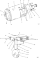
- the locking device 100 in the form of a lock cylinder, as is known to be used in mortise locks, in order to unlock a building door as a locking element or to be able to lock it by means of a bolt.
- the locking device 100 has a housing 101 with a recess in which a driver 103, which is designed as a locking lug, is rotatably arranged.
- the driver 103 is used to move a bolt in the locking or unlocking direction.
- the installation device 1 comprises a stator 10 in which a rotor 30 of the installation device 1 is inserted so that it can rotate about a rotor axis 35 which, for example, corresponds to the axis of rotation of the driver 103 .
- the rotor 30 On its front side 37 facing away from the driver 103, the rotor 30 comprises a key channel 36 for inserting a shank of a key 200.
- the key 200 carries an electronic locking code in the form of electronic data.
- the authorization of a user to unlock the door can be determined on the basis of the locking code.
- the key 200 is preferably designed without mechanical coding. Thus, it can only be determined on the basis of the electronic locking code whether the user has authorization or not.
- the key and the locking devices can be mechanically identical to each other.
- FIG. 12 shows the closure device 100 partially disassembled.
- the housing 101 has, for example in both halves of the recess for the driver 103, openings 104 in the lower area, of which the opening on the right is provided with a reference number.
- the openings 104 here extend perpendicularly to the axis of rotation of the driver 103.
- the driver 103 has, for example, an inner contour that is non-circular in cross section, for example in the form of internal teeth, into which an insert 105 preferably engages in a form-fitting manner.
- the insert 105 has an outer contour that is preferably designed to complement the inner contour of the driver 103, here in the form of external teeth, so that the two parts 103, 105 are arranged in a rotationally fixed manner with respect to one another.
- a connecting section 38 of the installation device 1 protrudes into the insert 105 .
- a coupling part 41 is slidably arranged in a guide 42 in the connecting section 38 .
- the coupling part 41 is designed in several parts. Depending on the position of the coupling part 41 , the coupling part 41 can establish or release an operative connection between the rotor 30 and the driver 103 , in particular via the insert 105 .
- the coupling part 41 of the locking device 100 can engage in a non-illustrated inner contour of the insert 105 in a form-fitting manner.
- the guide 42 preferably forms a linear guide for the coupling part 41, so that the coupling part 41 is arranged to be guided along the rotor axis 35 of the rotor 30 so that it can be moved.
- the installation device 1 has a cover 14 with which the installation device 1 is pushed into an associated insertion opening 106 of the housing 101 .
- a fastening element 102 in the form of a screw is screwed through the recess 104 on the right here from the underside of the housing 101 and into an opening 21 on the left here in the casing 14 of the stator 10 and a stator body 11 of the stator 10 explained in more detail later.
- the screw 102 thus fixes the stator 10 in the housing 101.
- the key channel 36 for inserting the key 200 which is formed in a first rotor element 32 of the rotor 30, is also designated here.
- the stator body 11 is also designed as a type of sleeve, but has functional structures on the inside.
- the stator body 11 has a stator recess 19 into which a stator insert element 13 is inserted.
- Component elements 12 which will be explained in more detail later, are attached or arranged on a side of the stator insert element 13 that faces the interior of the stator body 11 .
- the component elements 12 are movably mounted on the stator insert element 13 and the stator body 11 .
- the component elements 12 remain in the rest of the stator 10 when the rotor 30 rotates.
- the component elements 12 are therefore designed as stator elements 12 .
- the rotor 30 comprises the first rotor element 32 and a second rotor element 33.
- the rotor 30 is freely rotatable in the stator body 11 of the stator 10 but is mounted stationary in the direction of its rotor axis 35 , which runs parallel to the insertion direction of the key 200 into the key channel 36 .
- the coupling part 41 is arranged on the second rotor element 33 of the rotor 30 of the installation device 1 in a rotationally fixed manner.
- Both rotor elements 32, 33 are reversibly detachable, for example by means of a screw 24, fastened to one another and arranged in the stator body 11 so as to be freely rotatable.
- the second rotor element 33 has the guide 42 in which the coupling part 41 engages and is thus arranged in a rotationally fixed manner with respect to the second rotor element 33 .
- the second rotor element 33 is inserted into the stator body 11 from a base side 23 of the stator 10, preferably without the first rotor element 32 during assembly.
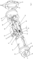
- FIG 4 shows the installation device 1 without the casing 14, the stator body 11 and the coupling part 41 in the partially dismantled state.
- An extension element 40 is intended to mechanically interact with the key 200 . If the key 200 is pushed into the key channel 36, it moves the extension element 40 axially or parallel to the rotor axis 35 upon contact.
- the key and thus the key channel 36 can have a small depth.
- the keyway 36 may be limited to the first rotor member 36 .
- the extension part 40 moves the coupling part 41 away from the rotor 30 in the direction of the driver 103 so that the coupling part 41 can engage the driver 103 in rotation.
- a passage 39 is provided in the connecting portion 38 for the extension member 40 to abut against the coupling member 41 .
- either the extension element 40 or the coupling part 41 can protrude through the passage 39 .
- a transmission element 44 here for example in the form of a coil, is provided in order to establish a data and/or energy transmission connection with the key 200.
- This makes it possible to read out electronic data, for example authentication information or an opening command, from the key 200 or to receive it from the key 200 .
- An electronic control device 53 is coupled to the coil in order to read out the data and, if necessary, evaluate it. If the control device 53 checks that the user of the key 200 is authorized to open the associated door and/or if the control device 53 has an opening command, an electromechanical actuator assembly 50 is activated.
- the actuator group 50 comprises an electromechanical actuator 52 here in the form of an electric motor, on the output shaft of which a blocking element 51 is arranged in a rotationally fixed manner. Blocking element 51 includes a recess 54, which will be explained in more detail later.
- a blocking element 31 is mounted in the second rotor element 33 so that it can move toward and away from the blocking element 51 , preferably perpendicular to the rotor axis 35 .
- the blocking element 31 In the first position shown here, the blocking element 31 is located in a blocking element recess 15 (see Fig. figure 5 ), which is formed by the stator insert element 13 and the stator elements 12. With this, the second rotor element 33 and thus the coupling part 41 are prevented from being rotated. The turning of the inserted key 200 to unlock the associated lock is blocked or prevented.
- a second position of the blocking element 31 (not shown), the blocking element 31 is disengaged from the blocking element recess 15 of the stator 10. This makes it possible to rotate the rotor 30 in the stator 10 and thus the driver 103.
- the blocking element 31 is held in place by at least one spring 34 (see Fig. figure 5 ), preferably several springs 34, are urged into the first position. In the embodiment of figure 5 several springs 34 are provided.
- Figures 5 to 7 show selected elements of the built-in device 1 4 . while showing figure 5 the arrangement of the blocking element 31 in relation to the blocking element 51 and the stator insert element 13 together with the stator elements 12.
- the blocking element 51 is between a release position in which the cutout 54 is opposite the blocking element 31 so that the blocking element 31 moves into the cutout 54 and locking positions in which the recess 54 does not oppose the locking member 31 so that the locking member 31 is prevented from entering the recess 54, rotatably.
- Blocking positions of the blocking element 51 are shown.
- the blocking element 31 is designed with a contact section 63 facing a blocking element 51 in order to be able to move into the recess 54 when the blocking element 51 is in the release position and the recess 54 is opposite the contact section 63 of the blocking element 31, in figure 5 i.e. pointing upwards. This makes it possible for the blocking element 31 to reach the second position.
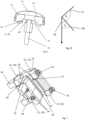
- a first contact surface 16 of the stator elements 12 facing the blocking element 31 is designed in such a way that the blocking element 31 is pushed in the direction of the blocking element 51, i.e. into the second position, when the rotor 30 rotates further, in which the rotor 30 can rotate freely in relation to the stator 10 is.
- the first contact surface 16 is designed as an inclined surface that pushes the blocking element 31 into the second position.
- the first contact surface can be straight, convex or concave.
- the stator elements 12 are movably mounted on the stator insert element 13 and the stator body 11 between a first position and a second position.
- the stator elements 12 are urged into the first position by means of spring elements 18 .
- the spring elements 18 are mounted in the stator 10 .
- the movement of the stator elements 12 from the first position to the second position according to the direction of movement 71 is perpendicular to the direction of movement 70 of the blocking element 31 at the beginning of the movement.
- the locking element 31 When the rotor 30 is unlocked relative to the stator 10, the locking element 31 is initially located in the locking element recess 15. The locking element 31 is guided in the rotor 30 in this case. In addition, the blocking element 31 is in contact with the first contact surfaces 16 of the stator elements 12 . As a result, the blocking element 31 is centered. This position of the blocking element 31 is referred to as the rest position. In the rest position, the blocking element 31 is preferably arranged at a distance from the blocking element 51 .
- the control device 53 controls the actuator 52 .
- the actuator 52 designed as an electric motor rotates the blocking element 51 into the release position in which the recess 54 is opposite the blocking element 31 . If the rotor 30 is now started to rotate using the key 200, the blocking element 31 slides along one of the first contact surfaces 16 into the second position, in which the blocking element 31 in the recess 54 engages. Here, the springs 34 are stretched. The blocking element 31 moves in the direction of movement 70.
- the first contact surfaces 16 form an acute angle ⁇ with the direction of movement 70 of the blocking element 31 (see Fig. figure 8 ).
- stator elements 12 remain in the first position. This is made possible by the fact that the spring elements 18 exert a greater force on the stator element 12, along which the blocking element 31 slides, than the springs 34 exert on the blocking element 31.
- the rotor 30 is now freely rotatable.
- the locking element 31 slides along that of the first contact surfaces 16 into which the locking element 31 is rotated.
- the locking element 31 is surrounded by the first contact surfaces 16 in both directions of rotation, so that rotation in both directions when it contacts at least one of the first contact surfaces 16 allows the locking element 31 to move into the second position.
- the blocking element recess 15 is surrounded on both sides by at least a first stator element 12, 12a and a second stator element 12, 12b (see Fig. figure 7 ).
- the stator 10 has a second contact surface 17 which leaves the blocking element 31 in the first position.
- the second contact surface 17 is functionally used when the user is not authorized to unlock the door.
- the second contact surfaces are formed in the stator insert element 13 . If the blocking element 31 is in the rest position, the second contact surfaces 17 are spaced further away from the blocking element 31 than the first contact surfaces 16.
- the second contact surfaces 17 are preferably also inclined, but in the opposite direction to the first contact surfaces 16 in relation to the direction of movement 70 of the locking element 31.
- the second contact surfaces 17 thus form an obtuse angle ⁇ to the direction of movement 70 of the locking element 31 (see figure 8 ).
- the blocking element 31 seen along the axis of rotation of the blocking element 51 and/or the rotor axis 35, has a cross section which has the shape of a preferably symmetrical trapezium tapering in the direction of the blocking element 51.
- the legs of this trapezoid form head surfaces 60 outwardly in relation to the blocking element 31.
- the head surface 60 and the corresponding contact surface 17 are designed to be inclined relative to the direction of movement of the blocking element 31.
- the sequence is as follows.
- the locking element 31 is initially in the rest position.
- a key 200 without a locking authorization is inserted into the keyway 36 .
- the electronic data exchange shows that there is no authorization to unlock the door. Therefore, the actuator 52 is not activated and the blocking element 51 remains in a blocking position, in which the recess 54 does not face the locking element 31, as in FIG figure 4 and 5 shown. Rather, an outer circumference of the blocking element 51 lies opposite the blocking element 31 .
- the blocking element 31 If the rotor 30 is rotated, the blocking element 31 tries to slide along the first contact surface 16 . However, this does not succeed since the blocking element 31 stands on an outer circumference of the blocking element 31 . Thus, the blocking element 31 cannot be pushed into the second position against the force of the springs 34 .
- stator element 12 which is located in the direction of rotation of the blocking element 31 , is pushed back by the blocking element 31 against the force of the spring 18 until the blocking element 31 rests against the second contact surface 17 .
- the stator element 12 is now in the second position.
- the head surface 60 of the blocking element 31 comes into contact with the corresponding second contact surface 17 opposite one of the legs of the trapezium.
- stator element 12 or the stator elements 12 have been moved back in the direction of rotation against the force of a spring element 18 .
- the spring element 18 presses the stator element 12 against the locking element 31 as the rotor 30 rotates further.
- the contact surface 17 is designed in such a way that the contact surface 17 holds the blocking element 31 in the first position. Thus, the rotor 30 remains blocked by the blocking element 31 so that the door cannot be unlocked.
- Every second contact surface 17 corresponds to a respective head surface 60 of the blocking element 31 facing the head surface 60.
- the surface 60 and the corresponding contact surface 17 are designed in such a way that the contact surface 17 is located between the surface 60 and the blocking element 51 when the blocking element 31 is on the contact surface 17 is applied.
- the blocking element 31 slides away from the blocking element 51 counter to the direction of movement 70 . This is achieved by the slope of the second contact surface 17.
- the blocking element 31 can slide along with the head surface 60 on the second contact surface 17 .
- the blocking element 31 and the blocking element 51 can thus be spaced apart from one another when they are in contact with the second contact surface 17 .
- the forces that act on the blocking element 31 in the event of further attempted rotation of the rotor 30 are diverted into the second contact surface 17 .
- a contributing factor here is that the head surfaces 60 correspond to the second contact surfaces and the blocking element 31 thus lies flat against the second contact surface.
- this makes it possible to mount the blocking element 51 on one side.
- FIG 5 the blocking element recess is provided with the reference number 15 .
- 6 shows the arrangement of figure 5 Seen from an end face of the blocking element 31, only without blocking element 51.
- the stator elements 12 are in the second position.
- FIG 7 are the same elements as in figure 6 presented in a different perspective. Additionally are in figure 7 the spring elements 18 shown and on the left side a spring seat 65 of the stator 10 for receiving the spring elements 18, while the spring seat 65 is not shown on the right side.
- the blocking element 31 is surrounded by the second contact surfaces 17 in both directions of rotation, so that the rotation in both directions of rotation when it rests against one of the second contact surfaces 17 leaves the blocking element 31 in the first position.
- the first contact surfaces 16 are closer to the blocking element 31 than the second contact surfaces 17.
- the second contact surfaces 17 protrude more into the blocking element recess 15 than the first contact surfaces 16.
- the first and the second contact surfaces 16, 17 are arranged axially one behind the other in the direction of the rotor axis 35.
- four first contact surfaces 16 are provided, for example, with two first contact surfaces 16 being provided in each direction of rotation of the rotor 30 .
- two first stator elements 12a are provided on one side of the locking element recess 15 and two second stator elements 12b are provided on the other side of the locking element recess 15 .
- the blocking element 31 extends in the axial direction in relation to the rotor axis 35 in such a way that the blocking element 31 can come into contact with both the first contact surface 16 and the second contact surface 17 .
- the locking element 31 is formed in one piece.
- first contact sections 64 of the blocking element 31, which are used to contact the first contact surfaces 16, are rigidly connected to the head surfaces 60, which are used to contact the second contact surfaces 17.
- the top surfaces 60 serve here as second contact sections.
- the first and the second abutment sections 60, 64 are rigidly connected to the third abutment section 63 of the locking element, which serves to abut in the recess 54.
- the first contact section 64 is adapted to the first contact surface 16, ie the blocking element 31 in the first contact section 64, for example as an in Can be designed towards blocking element 51 widening trapezoid. As a result, the blocking element 31 can slide flatly along the first contact surface 16 .
- the four stator elements 12, for example, are outwardly delimited on one side by a guide surface 62 of the stator insert element 13 during the movement between the first and the second position.
- the stator elements 12 are delimited on the inside by a guide surface, not shown, of the stator body 11 .
- stator comprises a stator body 11 and a stator insert body 13, assembly of the built-in element 1 is facilitated.
- the shell 14 serves to fasten the stator insert body 13 in the stator body 11 .
- the first rotor element 32 has a larger diameter than the second rotor element 33.
- the stator elements 12 and the stator insert body 13 are arranged in the portion of the stator 10 which surrounds the second rotor element 33. Due to the small diameter of the second rotor element 33, it is possible to provide the first and the second system sections 16, 17 in the stator 10.
- a peripheral projection 43 of the second rotor element 33 serves as a stop for the second rotor element 33 on the stator 10.
- the projection 43 is preferably designed in one piece with the second rotor element 33. As a result, the second rotor element 33 is fixed axially towards the front side 37 .
- the first rotor element 32 can be inserted into the stator 10 from the front side 37 .
- the first rotor element 32 is fixed axially towards the driver 103 by an end face 66 facing the second rotor element 33 .
- the end surface 66 is in contact with an inner structure of the stator 10 , in particular of the stator body 11 .
- the second rotor element 33 can be inserted from the base 23 until the projection 43 rests against the base 23 .
- a locking element 61 is provided, which holds the rotor 30 in position in relation to the stator 10 (see Fig. 4 ).
- a rotation of the rotor 30 is inhibited by the latching element 61 in the stator in such a way that the blocking element 31 can assume the rest position.
- the latching element 61 is formed, for example, by means of a spring-loaded latching lug. i.e. the rotor 30 can overcome the detent 61 when rotating, so that the function of the rotor 30 is maintained.
- An annular projection 22 is formed by means of, in particular, half-shell-like parts whose inner surfaces 26 facing one another interact with the key 200 in the manner of a bayonet catch. The parts are inserted into a peripheral groove 45 of the first rotor element 32 . Outwardly projecting projections 25 of the annular Projection 22 fix the parts of the projection 22 in the stator body 11 in their relative position to each other and to the stator body 11.
- the annular projection 22 acts with the inserted key 200 preferably like a bayonet as a key withdrawal lock.
- the extension element 40 is angled in the example shown.
- a first part of the extension element 40 which is intended to interact with the key 200, runs radially further outward than a second part of the extension element 40, which is intended to interact with the coupling part 41.
- the second part can be arranged more centrally in order to be able to push the coupling part 41 better.
- the extension element 40 is designed to push the coupling part 41 but without being positively engaged with the coupling part 41 . This enables the extension element 40 to be of filigree design.
- the extension element 40 serves to return the blocking element 51 mechanically and/or magnetically from the release position to the blocking position.
- the extension element 40 can be moved back into a starting position when the key is removed.
- a movement of the blocking element 51 into the blocking position can be caused or permitted.
- a spring (not shown) can be tensioned during the movement of the blocking element 51 into the release position.
- FIG. 9 shows a further embodiment of the locking device according to the invention. While showing figure 9 a view that the figure 4 corresponds, ie .the shell 14 and the stator body 11 are not shown. In the following, only the differences from the first embodiment of the Figures 1 to 8 discussed.
- the first rotor element 32 comprises fastening means 67 and the second rotor element 33 has fastening means 68 corresponding thereto, which interlock positively so that the first rotor element 32 and the second rotor element 33 are fastened to one another in a rotationally fixed manner in the direction of rotation.
- the first and the second fastening means 67, 68 are designed as projections and corresponding recesses.
- contact elements are provided as the transmission device 44, which transmit data and/or electrical energy to the locking device 1 via electrical contact with the key 200.
- the contact elements 44 are attached to a housing 46 in a resilient manner.
- the housing 46 also serves to fasten the rotor elements 32, 33 to one another axially.
- the housing 46 includes a first latching element 47 which latches into the first rotor element 32 .
- the first rotor element 32 has an edge 78 .
- the housing 46 has a second latching element 48 which latches into the second rotor element 33 .
- the second rotor element 33 includes a not shown groove.
- the first rotor element 32 is axially fixed by a snap ring 72 in either direction along the axis of rotation.
- the snap ring 72 is arranged in a groove 73 of the first rotor element 33 .
- the latching element 61 designed here as a ball, is arranged in the stator 10 and engages in a recess 69 in the first rotor element 32 .
- the installation device 1 can also be used in other locking devices, for example in a half cylinder, a knob cylinder, a furniture cylinder or a padlock.
- the coupling part 41 is missing. Rather, locking devices according to the invention can be provided in which the driver 103 is rigidly attached to the rotor 30 .
- the driver 103 can also serve as a bolt itself, z. B. in a furniture lock.
- the driver 103 and the insert 105 can be formed in one piece with each other.
- stator insert element 13 and the stator body 11 can be designed in one piece. It is also conceivable that the shell 14 is missing and the stator directly in the
- Locking device housing 101 is fixed.
- the locking device 1 is not designed as a built-in device 1 .
- the stator 10 is designed as a locking device housing 101 .
- the rotor 30 can thus be designed to be pushed directly into a lock cylinder housing 101 .
- the locking device housing 101 then takes over the function of the stator 10.
- the blocking element 31 can also be mounted in the stator 10 so that it is pressed against the rotor 30 .
- the first and the second bearing surfaces 16, 17 are formed in the rotor.
- the contact surfaces 16, 17 are designed in such a way that the first contact surfaces 16 or the second contact surfaces 17 enclose the second contact surfaces 17 or the first contact surfaces 16, respectively. However, they can also be arranged differently relative to one another.
- the transmission device 44 can be in the form of a contact element for making electrical contact with the key, or in the second exemplary embodiment it can be in the form of contactless coils.
- the attachment can be done by locking means as in the second embodiment.
- the actuator moves the blocking element back into the blocking position. This can be provided in particular for knob cylinders.
- the blocking element 51 can alternatively be designed in the form of a plunger.
- a preferably bistable magnet can be used as an actuator.
- the plunger may be spring loaded in one direction, preferably away from the magnet.
- the rotor 30 does not have to have a plurality of rotor elements 32, 33. Nevertheless, the rotor 30 can have sections with different diameters.
Landscapes
- Physics & Mathematics (AREA)
- Electromagnetism (AREA)
- Lock And Its Accessories (AREA)
- Snaps, Bayonet Connections, Set Pins, And Snap Rings (AREA)
Abstract
Description
- Die Erfindung betrifft eine elektromechanische Sperrvorrichtung für ein Verschlusselement oder für ein Schaltelement gemäß dem Oberbegriff von Anspruch 1. Solch eine Sperrvorrichtung ist mit einem Stator und einem Rotor als Bauteile sowie mit einem Sperrelement versehen. Der Rotor ist in dem Stator gelagert. Das Sperrelement ist in einem ersten Bauteil der Bauteile gelagert und zwischen einer ersten Stellung und einer zweiten Stellung bewegbar. In der ersten Stellung greift das Sperrelement in einem zweiten Bauteil der Bauteile ein. In der zweiten Stellung befindet sich das Sperrelement außer Eingriff mit dem zweiten Bauteil. Das zweite Bauteil weist eine erste Anlagefläche für das Sperrelement auf, die bei einer Drehung des Rotors das Sperrelement von der ersten Stellung in die zweite Stellung bewegt. Ferner betrifft die Erfindung eine mit solch einer Sperrvorrichtung ausgestattete Schließvorrichtung. Schließvorrichtungen gibt es in zahlreicher Ausführung beispielsweise in Form eines Schließzylinders.
- Die
EP 1 914 368 B1 offenbart einen Schließzylinder mit einem Sperrelement, das sich in einer ersten Stellung sowohl in einem Rotor als auch in einem Stator befindet und damit eine Drehung des Rotors gegenüber dem Stator blockiert. In einer zweiten Stellung des Sperrelements hingegen befindet sich das Sperrelement vollständig im Rotor, so dass der Rotor gegenüber dem Stator drehbar ist. Um aus der ersten Stellung in die zweite Stellung zu gelangen, wird ein Blockierelement in dem Rotor von einer Blockierposition in eine Freigabeposition gedreht. In der Freigabeposition erlaubt das Blockierelement die Bewegung des Sperrelements von der ersten Stellung in die zweite Stellung. Die Bewegung des Sperrelements wird durch schräge Anlageflächen im Stator hervorgerufen, die bei einer Drehung des Rotors das Sperrelement in die zweite Stellung drängen. Damit das Sperrelement in der ersten Stellung beabstandet von dem Blockierelement bleibt, ist ein Magnet vorgesehen, der das Sperrelement in der ersten Stellung hält. Nachteilig hieran ist, dass bei einer Bewegung des Rotors das Sperrelement stets durch die Anlageflächen zum Blockierelement gedrückt wird. Hierdurch können das Blockierelement und das Sperrelement Schaden nehmen. - Aufgabe der Erfindung ist es daher, eine gattungsgemäße Sperrvorrichtung so weiterzuentwickeln, dass der die Gefahr einer Beschädigung der Sperrvorrichtung, insbesondere des Blockierelements und/oder des Sperrelements, im Betrieb zumindest verringert ist. Insbesondere soll zudem eine mit solch einer Sperrvorrichtung versehene Schließvorrichtung geschaffen werden.
- Die Aufgabe wird gelöst durch den unabhängigen Anspruch 1. Vorteilhafte Weiterbildungen der Vorrichtung sind in den abhängigen Vorrichtungsansprüchen, der Beschreibung und in den Figuren angegeben. Ferner wird die Aufgabe auch durch eine Schließvorrichtung gemäß dem Anspruch 15 gelöst. Vorteilhafte Weiterbildungen der Schließvorrichtung sind in der Beschreibung und in den Figuren angegeben. Merkmale und Details, die in Zusammenhang mit der erfindungsgemäßen Sperrvorrichtung beschrieben sind, gelten dabei auch im Zusammenhang mit der erfindungsgemäßen Schließvorrichtung und umgekehrt. Dabei können die in der Beschreibung und in den Ansprüchen erwähnten Merkmale jeweils einzeln für sich oder in Kombination erfindungswesentlich sein.
- Erfindungsgemäß ist eine Sperrvorrichtung mit einem Stator und mit einem Rotor als Bauteile und einem Sperrelement vorgesehen. Der Rotor ist in dem Stator, insbesondere drehbar, gelagert. Das Sperrelement ist in einem ersten Bauteil der Bauteile gelagert und zwischen einer ersten Stellung und einer zweiten Stellung bewegbar. In der ersten Stellung greift das Sperrelement in einem zweiten Bauteil der Bauteile ein. In der zweiten Stellung befindet sich das Sperrelement außer Eingriff mit dem zweiten Bauteil. Das zweite Bauteil weist eine erste Anlagefläche für das Sperrelement auf, die bei einer Drehung des Rotors das Sperrelement von der ersten Stellung in die zweite Stellung bewegt. Erfindungsgemäß weist das zweite Bauteil eine zweite Anlagefläche für das Sperrelement auf, die das Sperrelement in der ersten Stellung belässt, in der sich das Sperrelement in Eingriffsstellung mit dem zweiten Bauteil befindet.
- Damit ist das Sperrelement bei einer Anlage an der zweiten Anlagefläche bevorzugt frei von Kräften, die das Sperrelement gegen ein anderes Element, insbesondere gegen ein Blockierelement, drücken könnten. Dies verringert die Gefahr einer Beschädigung des Sperrelements oder des Bockierelements.
- Das erste Bauteil kann dem Rotor oder dem Stator entsprechen. Entsprechend ist entspricht das zweite Bauteil dem anderen der Bauteile, d. h. entweder dem Stator oder dem Rotor. Somit kann entweder das Sperrelement in dem Rotor gelagert und in der ersten Stellung in den Stator eingreifen oder das Sperrelement ist in dem Stator gelagert und greift in der ersten Stellung in den Rotor ein. Bei der Lagerung des Sperrelements handelt es sich bevorzugt um eine lineare Führung.
- In der ersten Stellung verhindert das Sperrelement eine Drehung des Rotors in dem Stator. Hierbei wird unter einer Verhinderung einer Drehung das Verhindern um einen relevanten Drehbereich verstanden, z. B. um ein Verschlusselement entriegeln zu können. In der zweiten Stellung ermöglicht das Sperrelement eine Drehung des Rotors in dem Stator.
- Dadurch, dass das Sperrelement bei der Anlage an der zweiten Anlagefläche in der ersten Stellung verbleibt, ist eine weitere Drehung des Rotors gegenüber dem Stator verhindert. Dadurch, dass die zweite Anlagefläche das Sperrelement in der ersten Stellung belässt, wird, wenn eine Drehung des Rotors versucht wird, die Drehung des Rotors bei einer Anlage des Sperrelements an der zweiten Anlagefläche gestoppt. Hierbei wird durch die zweite Anlagefläche keine Kraft auf das Sperrelement in Richtung der ersten Stellung ausgeübt.
- Die Sperrvorrichtung dient bevorzugt zum Verriegeln eines räumlichen Bereichs. Der räumliche Bereich ist insbesondere feststehend. Beispielsweise kann es sich bei dem räumlichen Bereich um einen Gebäuderaum, beispielsweise um ein Büro, eine Wohnung oder ein Haus, oder um einen Aufbewahrungsraum, beispielsweise einen Schrank, einen Briefkasten, eine Truhe, einen Kasten, einen Tresor oder eine Schublade, handeln. Insbesondere dient die Sperrvorrichtung dazu, in einem insbesondere türenartigen Verschlusselement, beispielsweise einer Haustür, einer Wohnungstür, einer Zimmertür, einer Schranktür, einer Briefkastenklappe oder der Vorderseite einer Schublade eingesetzt zu werden oder an einem Verschlusselement angebracht zu werden. Bevorzugt ist der Stator der Sperrvorrichtung hierbei zumindest mittelbar mit dem Verschlusselement drehfest verbunden.
- Die Sperrvorrichtung kann einen Mitnehmer aufweisen oder mit einem Mitnehmer verbindbar sein. Eine Drehung des Rotors der Sperrvorrichtung dient dazu, den Mitnehmer zu drehen.
- Der Mitnehmer ist vorzugsweise als Exzenter ausgebildet. Der Mitnehmer kann als Schließnase ausgebildet sein. Es kann sein, dass eine Drehung des Mitnehmers in einer ersten Richtung dazu dient, das Verschlusselement von einem entriegelten Zustand in einen verriegelten Zustand zu überführen. Es kann sein, dass eine Drehung des Mitnehmers in eine zweite Richtung dazu dient, dass Verschlusselement von einem verriegelten in einen entriegelten Zustand zu überführen. Beispielsweise kann die Sperrvorrichtung zumindest mittelbar in ein Einsteckschloss eingesetzt werden. Eine Drehung des Mitnehmers kann in diesem Fall eine Bewegung des Riegels des Einsteckschlosses bewirken. So kann die Drehung des Mitnehmers in eine erste Richtung z. B. ein Ausfahren des Riegels und damit ein Herbeiführen des verriegelten Zustands des Verschlusselements bewirken. Eine Drehung des Mitnehmers in eine zweite Richtung kann z. B. ein Einfahren des Riegels und damit ein Herbeiführen des entriegelten Zustands des Verschlusselements bewirken.
- Alternativ kann der Mitnehmer selbst als Riegel wirken. So kann die Drehung des Mitnehmers in eine erste Richtung z. B. die Einnahme einer Verriegelungsposition des Mitnehmers bewirken. Die Drehung des Mitnehmers in eine zweite Richtung z. B. die Einnahme einer Entriegelungsposition des Mitnehmers bewirken.
- In einer bevorzugten Ausführungsform ist die Sperrvorrichtung als eine Einbauvorrichtung ausgebildet. Die Einbauvorrichtung ist ausgebildet, in ein Schließvorrichtungsgehäuse einer Schließvorrichtung eingesetzt zu werden. Bevorzugt wird die Einbauvorrichtung in dem Schließvorrichtungsgehäuse mittels eines Befestigungselements drehfest befestigt. Somit bilden im montierten Zustand der Schließvorrichtung der Stator der Sperrvorrichtung und das Schließvorrichtungsgehäuse eine gemeinsame feststehende Einheit. Das Schließvorrichtungsgehäuse dient insbesondere zum Einsetzen in oder Anbringen an dem Verschlusselement. Die Schließvorrichtung kann beispielsweise als Schließzylinder, insbesondere als Doppelzylinder oder Halbzylinder, als Knaufzylinder, als Möbelzylinder oder als Hängeschloss ausgebildet sein.
- Die Sperrvorrichtung, insbesondere der Rotor, können mit einem Knauf oder mit einem Schlüssel verbunden oder verbindbar sein, um ein mechanisches Drehmoment auf den Rotor zu übertragen.
- Ist die Sperrvorrichtung als Einbauvorrichtung ausgebildet, so ist vorzugsweise vorgesehen, dass die Sperrvorrichtung einen Verbindungsabschnitt umfasst, um mit einem Mitnehmer verbunden zu werden.
- Alternativ kann es vorgesehen sein, dass die Sperrvorrichtung selber als Schließzylinder, insbesondere als Doppelzylinder oder Halbzylinder, als Knaufzylinder, als Möbelzylinder oder als Hängeschloss ausgebildet sein. Hierbei dient der Stator zugleich als Gehäuse zum Einsetzen in oder Anbringen an dem Verschlusselement.
- Alternativ kann die Sperrvorrichtung für ein Schaltelement vorgesehen sein. So kann das Schaltelement nur von berechtigten Benutzern bedient werden. Der Mitnehmer kann hierbei dazu dienen, einen Schalter oder Taster zu betätigen. Somit kann die Sperrvorrichtung in einem Schaltelement, insbesondere in einem Schlüsselschalter, eingesetzt sein oder einem Schlüsselschalter entsprechen.
- Die elektromechanische Sperrvorrichtung umfasst insbesondere einen elektromechanischen Aktuator, insbesondere einen Elektromotor. Der Aktuator dient dazu, es zu ermöglichen, dass das Sperrelement in die zweite Stellung bewegt wird.
- Die Sperrvorrichtung kann eine elektronische Steuerungsvorrichtung, insbesondere einen Prozessor und/oder einen Controller, umfassen, um den Aktuator anzusteuern. Die Steuerungsvorrichtung kann einen elektronischen Speicher umfassen.
- Die Sperrvorrichtung kann eine Übertragungsvorrichtung umfassen. Die Übertragungsvorrichtung kann als eine Sende- und Empfangseinheit, als ein biometrischer Sensor, als ein Tastenfeld zur PIN-Eingabe und/oder als ein Kontaktelement zur elektrischen Kontaktierung eines insbesondere elektronischen Schlüssels ausgebildet sein. Die Sende- und Empfangseinheit kann ausgebildet sein, mit einer mobilen Einheit, insbesondere einem Mobiltelefon oder einer Karte, durch kabellose Nahbereichskommunikation, insbesondere RFID oder Bluetooth Low Energy, zu kommunizieren.
- Die Übertragungsvorrichtung kann dazu dienen, elektronische Daten zu senden und/oder zu empfangen, die es ermöglichen, eine Berechtigung eines Benutzers zum Entriegeln des räumlichen Bereichs oder zum Betätigen des Schaltelements festzustellen. Beispielsweise kann die Übertragungsvorrichtung einen Berechtigungscode und/oder ein Berechtigungszeitfenster empfangen, der von der Steuerungsvorrichtung überprüft wird. Ist die Überprüfung mit einem positiven Ergebnis abgeschlossen, kann der Aktuator angesteuert werden, um dem Sperrelement eine Bewegung in die zweite Stellung zu ermöglichen.
- Alternativ kann die Übertragungsvorrichtung einen Öffnungsbefehl empfangen, aufgrund dessen das Sperrelement elektromechanisch in die zweite Stellung bewegt wird oder elektromechanisch die Bewegung in die zweite Stellung freigegeben wird. Die Übertragungsvorrichtung dient insbesondere zusätzlich oder alternativ dazu, elektrische Energie auf die Sperrvorrichtung zu übertragen. Die elektrische Energie kann zur Betätigung des Aktuators und/oder für die Steuerungsvorrichtung vorgesehen sein.
- Vorzugsweise umfasst die erfindungsgemäße Sperrvorrichtung ein Blockierelement. Die Sperrvorrichtung kann eine elektromechanische Aktuatorbaugruppe mit dem Blockierelement und dem Aktuator umfassen.
- Bevorzugt ist, vorgesehen, dass das Blockierelement in einer Freigabeposition die Bewegung des Sperrelements von der ersten Stellung in die zweite Stellung zulässt und in einer Blockierposition die Bewegung des Sperrelements von der ersten Stellung in die zweite Stellung verhindert. Der Aktuator dient bevorzugt dazu, eine Bewegung des Blockierelements von der Blockierposition in die Freigabeposition zu ermöglichen. So kann der Aktuator das Blockierlement in die Freigabeposition bewegen und/oder z. B. über das Spannen einer Feder eine Bewegung des Blockierelements in die Freigabeposition veranlassen.
- Insbesondere kann vorgesehen sein, dass, wenn sich das Blockierelement in der Freigabeposition befindet, die Drehung des Rotors eine Bewegung des Sperrelements in die zweite Stellung ermöglicht, insbesondere hervorruft. Hierbei drängt insbesondere die erste Anlagefläche das Sperrelement in die zweite Stellung.
- Die zweite Anlagefläche ist insbesondere derart ausgebildet, dass das Sperrelement durch die Anlage an der zweiten Anlagefläche von dem Blockierelement beabstandet ist. Hierdurch kann eine Beschädigung der Sperrvorrichtung verhindert werden.
- Das Blockierelement und das Sperrelement können in der ersten Stellung des Sperrelements beabstandet voneinander sein, insbesondere wenn das Sperrelement unbelastet ist und/oder wenn das Sperrelement an der zweiten Anlagefläche anliegt.
- Vorzugsweise umfasst die Aktuatorbaugruppe den elektromechanischen Aktuator.
- Es kann vorgesehen sein, dass das Blockierelement auf der Ausgangswelle des als Elektromotor ausgebildeten Aktuators angeordnet ist. Vorzugsweise ermöglicht der Aktuator eine Drehung des Blockierelements von der Blockierposition in die Freigabeposition. Beispielsweise dreht der Aktuator das Blockierelement von der Blockierposition in die Freigabesposition. Dies erlaubt eine sehr raumsparende Ausführung.
- Insbesondere dadurch, dass die zweite Anlagefläche das Sperrelement von dem Blockierelement beanstandet, ist es möglich, das Blockierelement einseitig zu lagern. So kann die Ausgangswelle nur einseitig in dem Aktuator gelagert sein. Kräfte, die von dem Sperrelement auf das Blockierelement wirken, können einseitig, insbesondere über die Ausgangswelle, abgeleitet werden.
- Insbesondere, um das Blockierelement und das Sperrelement bei Anlage an der zweiten Anlagefläche zu beabstanden, kann das Sperrelement eine vorspringende Kopffläche umfassen. Die zweite Anlagefläche kann dazu korrespondieren ausgebildet sein. Die Kopffläche und die zweite Anlagefläche sind derart ausgebildet, dass sich bei Anlage des Sperrelements an der zweiten Anlagefläche die zweite Anlagefläche zwischen der Kopffläche und dem Blockierelement befindet.
- Alternativ oder zusätzlich definiert die Bewegung des Sperrelements zwischen der ersten und der zweiten Stellung eine Bewegungsrichtung, wobei die Kopffläche und die zweite Anlagefläche geneigt zu der Bewegungsrichtung des Sperrelements ausgebildet sind. Hierdurch können Kräfte, die auf das Sperrelement wirken, in den Stator geleitet werden.
- Bevorzugt umfasst das Blockierelement eine Aussparung, in die das Sperrelement in der zweiten Stellung angeordnet ist. In der ersten Stellung hingegen befindet sich das Sperrelement außerhalb der Aussparung. In der Freigabeposition ist das Blockierelement so angeordnet, dass die Aussparung dem Sperrelement gegenüberliegt, so dass das Sperrelement in die Aussparung einfahren kann.
- Das Blockierelement kann beispielsweise scheibenförmig ausgebildet sein.
- Vorzugsweise umfasst das zweite Bauteil ein Bauteilelement, das die erste Anlagefläche aufweist und in dem übrigen zweiten Bauteil beweglich gelagert ist. Insbesondere kann hierdurch erreicht werden, dass durch eine Bewegung des Bauteilelements das Sperrelement zur Anlage an die zweiten Anlagefläche gelangt. Das Bauteilelement weist vorzugsweise keine feste Verbindung oder Lagerung zu dem ersten Bauteil auf.
- Es kann vorgesehen sein, dass sich das Bauteilelement und das Sperrelement bei einer Drehung des Rotors relativ zueinander bewegen. In der Freigabeposition des Blockierelements bewegt sich das Sperrelement von der ersten Stellung in die zweite Stellung. In der Blockierposition des Blockierelements bewegt sich das Bauteilelement, so dass das Sperrelement zur Anlage an die zweite Anlagefläche gelangt.
- Es kann vorgesehen sein, dass das Bauteilelement zwischen einer ersten Position und einer zweiten Position bewegbar ist. In der ersten Position liegt die erste Anlagefläche an dem Sperrelement derart an, dass bei einer Drehung des Rotors das Sperrelement von der ersten Stellung in die zweite Stellung bewegt wird. In der zweiten Position des Bauteilelements kommt das Sperrelement derart an der zweiten Anlagefläche zur Anlage, sodass das Sperrelement in der ersten Stellung verbleibt. D. h. das Bauteilelement muss bei der vorgenannten Rotation zunächst in die gewünschte zweite Position bewegt werden, damit die zweite Anlagefläche wirksam werden kann. Dies ermöglicht ein gezieltes Initiieren der Bewegung des Sperrelements von der ersten in die zweite Stellung bzw. ein gezieltes Verbleiben in der ersten Stellung.
- Zumindest eine Sperrelement-Ausnehmung ist zwischen dem zumindest einen ersten Bauteilelement und dem zumindest einem zweite Bauteilelement definiert, in der das Sperrelement in der ersten Stellung angeordnet ist. Die Rotation des Rotors wird insbesondere durch Eingriff des Sperrelements in die Sperrelement-Ausnehmung in der ersten Stellung des Sperrelements verhindert. In der zweiten Stellung befindet sich das Sperrelement außerhalb der Sperrelement-Ausnehmung.
- Die ersten Anlagefläche befinden sich in der ersten Position des Bauteilelements näher an dem Sperrelement als die zweiten Anlagefläche. Die erste Anlagefläche begrenzt in der ersten Position des Bauteilelements die Sperrelement-Ausnehmung. In der zweiten Position des Bauteilelements ragt die zweiten Anlagefläche mehr in die Sperrelement-Ausnehmung hinein als die erste Anlagefläche.
- Sind mehrere Sperrelement-Ausnehmungen vorgesehen, z. B. damit das Sperrelement aus einer Ruheposition nach einer Drehung des Rotors über einen Drehwinkelbereich des Rotors kleiner als 360° erneut in die erste Stellung gelangen kann, so werden die Sperrelementausnehmungen bevorzugt jeweils von ersten Anlageflächen und zweiten Anlageflächen umgeben, wie für eine Sperrelement-Ausnehmung geschildert.
- Die Bewegung des Bauteilelements zwischen der ersten Position und der zweiten Position umfasst bevorzugt eine senkrechte Komponente zur Bewegung des Sperrelements zwischen der ersten Stellung und der zweiten Stellung. Insbesondere erfolgt die Bewegung des Bauteilelements zwischen der ersten und der zweiten Position senkrecht zu der Bewegung des Sperrelements von der ersten Stellung in die zweite Stellung.
- Das zweite Bauteil kann zumindest ein Federelement umfassen, das das Bauteilelement in die erste Position drängt, wobei das Federelement in dem zweiten Bauteil gelagert ist. Dadurch erfolgt eine Rückstellung des Bauteilelements in die erste Position automatisch, was eine einfachere Bewegungssteuerung ermöglicht.
- Vorzugsweise ist das Sperrelement durch eine Feder in die erste Stellung vorgespannt.
- Bevorzugt ist vorgesehen, dass die Kraft, die durch die Feder auf das Sperrelement wirkt, kleiner ist als die Kraft, die durch das Federelement auf das Bauteilelement wirkt. Es kann sein, dass die Federkonstante der Feder kleiner als die Federkonstante des Federelements ausgebildet ist. Dadurch ist es dem Federelement möglich, dass das Bauteilelement in der ersten Position verbleibt, wenn das Sperrelement in die zweite Stellung ausweichen kann.
- Bevorzugt ist das Sperrelement zwischen zumindest einem ersten Bauteilelement und zumindest einem zweiten Bauteilelement angeordnet. Somit wird sowohl bei einer Drehung des Rotors in dem Uhrzeigersinn als auch gegen den Uhrzeigersinn, dass Sperrelement durch die erste Anlagefläche in die zweite Stellung bewegt, sofern das Blockierelement die Bewegung in die zweite Stellung zulässt.
- Es kann vorgesehen sein, dass das zumindest eine erste Bauteilelement und/oder das zumindest eine zweite Bauteilelement an dem Sperrelement in der ersten Stellung anliegen.
- Bevorzugt ist das Sperrelement zwischen zweiten Anlageflächen angeordnet. Somit wird sowohl bei einer Drehung des Rotors in dem Uhrzeigersinn als auch gegen den Uhrzeigersinn das Sperrelement gegen eine zweite Anlagefläche bewegt, wenn eine Bewegung des Sperrelements in die zweite Stellung insbesondere durch das Blockierelement verhindert ist.
- Bevorzugt ist das erste Bauteil als der Rotor und das zweite Bauteil als der Stator ausgebildet. Somit ist das Sperrelement in dem Rotor beweglich gelagert und greift in der ersten Stellung in die Sperrelement-Ausnehmung des Stators ein.
- Vorzugsweise befindet sich das Sperrelement im Rotor. Der Stator umfasst das Bauteilelement. Das Bauteilelement ist in diesem Fall als Statorelement ausgebildet. In diesem Falle dreht sich das Sperrelement mit dem Rotor. Hingegen dreht sich das Bauteilelement nicht mit dem Rotor. Das Bauteilelement verbleibt bei einer Drehung des Rotors im Stator. Durch die Lagerung des Bauteilelements im Stator ist bevorzugt das Bauteilelement in einem vorgegebenen Bereich im Stator beweglich. Der Bereich selber ist hingegen vorzugsweise ortsfest.
- Insbesondere wenn das zweite Bauteil als Stator ausgebildet ist, umfasst der Stator vorzugsweise einen Statorkörper und/oder zumindest ein Statoreinsatzelement. Hierdurch kann die Montage vereinfacht sein.
- Der Statorkörper kann eine vom Außenumfang zugängliche Stator-Aussparung umfassen, in der das Statoreinsatzelement einsetzbar ist.
- Vorzugsweise umfasst das Statoreinsatzelement die zweite Anlagefläche.
- Es kann vorgesehen sein, dass das Statoreinsatzeleement eine Führungfläche für das Statorelement, bevorzugt für das erste und das zweite Statorelement, umfasst.
- Insbesondere kann der Stator eine Hülle umfassen. Dabei ist bzw. sind der übrige Stator, insbesondere der Statorkörper, das Statoreinsatzelement und/oder das Statorelement in die Hülle eingesetzt.
- Es kann vorgesehen sein, dass der Rotor zumindest einen ersten axialen Abschnitt, insbesondere eine erstes Rotorelement, und einen zweiten axialen Abschnitt, insbesondere ein zweites Rotorelement, umfasst. Der zweite Abschnitt umfasst bevorzugt einen geringeren Durchmesser als der erste Abschnitt.
- Es kann vorgesehen sein, dass das Sperrelement in dem zweiten axialen Abschnitt angeordnet ist. Hierdurch ist genügend Bauraum im Stator vorhanden, um die erste und die zweite Anlagefläche vorzusehen. Bevorzugt ist hierdurch genügend Bauraum im Stator vorgesehen, um das Statorelement oder die Statorelemente vorzusehen.
- Bei allen genannten Ausführungen können die erste Anlagefläche und die zweite Anlagefläche, bezogen auf die Rotorachse, axial hintereinander angeordnet sein. Insbesondere umschließt die erste Anlagefläche die zweite Anlagefläche axial. Somit sind in jeder Drehrichtung eine zweite Anlagefläche vorgesehen, die von mehreren ersten Anlageflächen umschlossen ist. Dadurch ist ein gleichmäßiges Verschieben des Sperrelements ermöglicht.
- Vorzugsweise umfasst das Sperrelement einen ersten Anlageabschnitt zur Anlage an die erste Anlagefläche und einen zweiten Anlageabschnitt zur Anlage an die zweite Anlagefläche. Dabei sind der erste Anlageabschnitt und der zweite Anlageabschnitt bevorzugt starr miteinander verbunden. Der erste Anlageabschnitt und der zweite Anlageabschnitt sind bevorzugt in axialer Richtung hintereinander angeordnet. Dies ermöglicht einen einfachen Aufbau des Sperrelements.
- Der erste Anlageabschnitt kann korrespondierend zur ersten Anlagefläche ausgebildet sein, so dass der erste Anlageabschnitt und die erste Anlagefläche flächig aneinander anliegen können.
- Der zweite Anlageabschnitt kann korrespondierend zur zweiten Anlagefläche ausgebildet sein, so dass der zweite Anlageabschnitt und die zweite Anlagefläche flächig aneinander anliegen können.
- Es kann vorgesehen sein, dass sich das Sperrelement derart erstreckt, dass das Sperrelement nur durch die Drehung des Rotors zu der zweiten Anlagefläche zur Anlage kommen kann. Beispielsweise ist es nicht nötig, das Sperrelement axial zur Rotorachse zu versetzen, damit das Sperrelement zur Anlage an die zweite Anlagefläche kommt.
- Es kann vorgesehen sein, dass sich das Sperrelement in axiale Richtung bezogen auf die Rotorachse vorzugsweise derart erstreckt, dass das Sperrelement sowohl zu der ersten Anlagefläche als auch der zweiten Anlagefläche zur Anlage kommen kann.
- Die Sperrelement-Ausnehmung umfasst eine erste Seite, an die das Sperrelement bei einer Rechtsdrehung des Rotors zur Anlage kommt, und eine zweite Seite, an die das Sperrelement bei einer Linksdrehung des Rotors zur Anlage kommt, wobei auf der ersten Seite und auf der zweiten Seite die erste und die zweite Anlagefläche vorgesehen sind.
- Vorzugsweise umfasst das Sperrelement einen dritten Anlageabschnitt zur Anlage an das Blockierelement, insbesondere zum Eingriff in das Blockierelement. Der dritte Anlageabschnitt ist bevorzugt starr mit dem ersten Anlageabschnitt und/oder dem zweite Anlageabschnitt verbunden.
- Insbesondere kann die Sperrvorrichtung ein Rastelement zum Rasten in zumindest einer Position des Rotors gegenüber dem Stator umfassen. Das Rastelement hält den Rotor in einer Position, in der das Sperrelement nicht von der ersten Anlagefläche zum Blockierelement gedrängt wird.
- Dadurch wird das Sperrelement sicher in dieser Position gehalten und kann diese Position nicht ungewollt verlassen.
- Bei allen genannten Varianten kann das Sperrelement einteilig ausgebildet sein.
- Ferner ist erfindungsgemäß eine Schließvorrichtung vorgesehen, die mit der erfindungsgemäßen Sperrvorrichtung versehen ist. Hierbei ist die Sperrvorrichtungen als Einbauvorrichtung ausgebildet.
- Die Erfindung wird nachfolgend anhand von Ausführungsbeispielen näher erläutert. Technische Merkmale mit gleicher Funktion sind in den Figuren mit identischen Bezugszeichen versehen. Es zeigen:
- Fig.1
- eine erfindungsgemäße Schließvorrichtung und einen Schlüssel,
- Fig. 2
- die Schließvorrichtung aus
Fig. 1 , die teilweise auseinander gebaut ist, mit einer perspektivischen Sicht auf eine erfindungsgemäße Sperrvorrichtung, die als Einbauvorrichtung ausgebildet ist, - Fig. 3
- die erfindungsgemäße Sperrvorrichtung aus
Fig. 2 ohne Hülle, - Fig. 4
- die Sperrvorrichtung aus
Figur 3 ohne Hülle und Statorkörper in einer Explosionsdarstellung, - Fig. 5, 6, 7
- ausgewählte Elemente der Einbauvorrichtung aus
Fig. 4 , - Fig. 8
- eine Prinzipiendarstellung der Neigungswinkel einer ersten und zweiten Anlagenfläche der erfindungsgemäßen Sperrvorrichtung und
- Fig. 9
- eine erfindungsgemäße Sperrvorrichtung gemäß einem zweiten Ausführungsbeispiel im teilweise demontierten Zustand.
-
Fig. 1 zeigt eine Schließvorrichtung 100 in Form eines Schließzylinders, wie er bekanntermaßen in Einsteckschlössern Verwendung findet, um eine Gebäudetür als Verschlusselement zu entriegeln oder mittels eines Riegels verriegeln zu können. Dazu weist die Schließvorrichtung 100 ein Gehäuse 101 mit einer Ausnehmung auf, in der ein Mitnehmer 103, der als Schließnase ausgebildet ist, drehbar angeordnet ist. Der Mitnehmer 103 dient dazu, einen Riegel in Ver- oder in Entriegelungsrichtung zu bewegen. - In der hier rechten Hälfte des Gehäuses 101 ist eine als Einbauvorrichtung ausgebildete Sperrvorrichtung 1 gemäß einem Ausführungsbeispiel der Erfindung eingesetzt. Die Einbauvorrichtung 1 umfasst einen Stator 10, in dem ein Rotor 30 der Einbauvorrichtung 1 um eine Rotorachse 35 rotierbar eingesetzt ist, die exemplarisch mit der Rotationsachse des Mitnehmers 103 übereinstimmt. Der Rotor 30 umfasst an seiner dem Mitnehmer 103 abgewandten Frontseite 37 einen Schlüsselkanal 36 zum Einschieben eines Schafts eines Schlüssels 200. Der Schlüssel 200 trägt ein elektronisches Schließgeheimnis in Form von elektronischen Daten. Anhand des Schließgeheimnis lässt sich die Berechtigung eines Benutzers zum Entriegeln der Tür feststellen. Der Schlüssel 200 ist bevorzugt ohne eine mechanische Codierung ausgebildet. Somit ist nur anhand des elektronischen Schließgeheimnis feststellbar, ob der Benutzer eine Berechtigung besitzt oder nicht. Hierbei können die Schlüssel und die Sperrvorrichtungen mechanisch identisch zueinander ausgebildet sein.
-
Fig. 2 zeigt die Schließvorrichtung 100, die teilweise auseinander gebaut ist. Das Gehäuse 101 weist, beispielsweise in beiden Hälften der Ausnehmung für den Mitnehmer 103, im unteren Bereich Öffnungen 104 auf, von denen die rechte Öffnung mit einem Bezugszeichen versehen ist. Die hier Öffnungen 104 erstrecken sich senkrecht zur Rotationsachse des Mitnehmers 103. Der Mitnehmer 103 weist exemplarisch inwendig eine im Querschnitt nicht kreisförmige Innenkontur beispielhaft in Form einer Innenverzahnung auf, in die ein Einsatz 105 vorzugsweise formschlüssig eingreift. Dazu weist der Einsatz 105 eine zur Innenkontur des Mitnehmers 103 vorzugsweise komplementär gestaltete Außenkontur hier in Form einer Außenverzahnung auf, sodass beide Teile 103, 105 drehfest zueinander angeordnet sind. - In den Einsatz 105 ragt ein Verbindungsabschnitt 38 der Einbauvorrichtung 1 hinein. In dem Verbindungsabschnitt 38 ist ein Kupplungsteil 41 verschiebbar in einer Führung 42 angeordnet. Das Kupplungsteil 41 ist mehrteilig ausgebildet. Das Kupplungsteil 41 kann je nach Position des Kupplungsteils 41 eine Wirkverbindung zwischen dem Rotor 30 und dem Mitnehmer 103, insbesondere über den Einsatz 105, herstellen oder freigeben. Hierzu kann das Kupplungsteil 41 der Schließvorrichtung 100 formschlüssig in eine nicht dargestellte Innenkontur des Einsatzes 105 eingreifen. Die Führung 42 bildet vorzugsweise eine Linearführung für das Kupplungsteil 41, sodass das Kupplungsteil 41 entlang der Rotorachse 35 des Rotors 30 geführt bewegbar angeordnet ist.
- Die Einbauvorrichtung 1 weist eine Hülle 14 auf, mit der die Einbauvorrichtung 1 in eine zugehörige Einschuböffnung 106 des Gehäuses 101 eingeschoben ist. Eine Befestigungselement 102 in Form einer Schraube ist durch die hier rechte Ausnehmung 104 von der Unterseite des Gehäuses 101 her und in eine hier linke Öffnung 21 der Hülle 14 des Stators 10 und eines später näher erläuterten Statorkörpers 11 des Stators 10 eingeschraubt. Damit fixiert die Schraube 102 den Stator 10 im Gehäuse 101. Ferner ist hier der Schlüsselkanal 36 zum Einführen des Schlüssels 200 bezeichnet, der in einem ersten Rotorelement 32 des Rotors 30 ausgebildet ist.
-
Fig. 3 zeigt die Einbauvorrichtung 1 ohne Hülle 14. Der Statorkörper 11 ist ebenfalls als eine Art Hülse ausgebildet, weist inwendig aber funktionale Strukturen auf. Der Statorkörper 11 weist eine Stator-Aussparung 19 auf, in die ein Statoreinsatzelement 13 eingesetzt ist. An einer dem Inneren des Statorkörpers 11 zugewandten Seite des Statoreinsatzelements 13 sind später näher erläuterte Bauteilelemente 12 angebracht bzw. angeordnet. Die Bauteilelemente 12 sind an dem Statoreinsatzelement 13 und dem Statorkörper 11 beweglich gelagert. Die Bauteilelemente 12 verbleiben bei einer Drehung des Rotors 30 in dem übrigen Stator 10. Somit sind die Bauteilelemente 12 als Statorelemente 12 ausgebildet. - Der Rotor 30 umfasst das erste Rotorelement 32 und ein zweites Rotorelement 33.
- Der Rotor 30 ist im Statorkörper 11 des Stators 10 frei rotierbar, aber ortsfest in Richtung seiner Rotorachse 35 gelagert, die parallel zur Einschubrichtung des Schlüssels 200 in den Schlüsselkanal 36 verläuft. Das Kupplungsteil 41 ist auf dem zweiten Rotorelement 33 des Rotors 30 der Einbauvorrichtung 1 drehfest angeordnet. Beide Rotorelemente 32, 33 sind reversibel lösbar, beispielsweise vermittels einer Schraube 24, aneinander befestigt und im Statorkörper 11 frei rotierbar angeordnet.
- Das zweite Rotorelement 33 weist die Führung 42 auf, in die das Kupplungsteil 41 eingreift und somit drehfest zum zweiten Rotorelement 33 angeordnet ist. Das zweite Rotorelement 33 ist von einer Grundseite 23 des Stators 10 her in den Statorkörper 11 eingesetzt, und zwar bei der Montage vorzugsweise ohne das erste Rotorelement 32.
-
Fig. 4 zeigt die Einbauvorrichtung 1 ohne Hülle 14, Statorkörper 11 und Kupplungsteil 41 im teilweise demontierten Zustand. - Ein Verlängerungselement 40 ist vorgesehen, mit dem Schlüssel 200 mechanisch zu interagieren. Wird der Schlüssel 200 in den Schlüsselkanal 36 eingeschoben, bewegt er bei Kontakt das Verlängerungselement 40 axial bzw. parallel zu der Rotorachse 35. Hierdurch kann das Verlängerungselement 40 den Wirkungskreis des Schlüssels 200 verlängern. Der Schlüssel und damit der Schlüsselkanal 36 können dabei eine geringe Tiefe aufweisen. Beispielsweise kann der Schlüsselkanal 36 auf das erste Rotorelement 36 beschränkt sein.
- Dabei bewegt das Verlängerungsteil 40 das Kupplungsteil 41 vom Rotor 30 weg in Richtung Mitnehmer 103, sodass das Kupplungsteil 41 mit dem Mitnehmer 103 in Rotationseingriff gelangen kann. Ein Durchgang 39 ist in dem Verbindungsabschnitt 38 vorgesehen, damit das Verlängerungselement 40 zur Anlage an das Kupplungsteil 41 gelangt. Hierbei kann entweder das Verlängerungselement 40 oder das Kupplungsteil 41 den Durchgang 39 durchragen.
- Ein Übertragungselement 44, hier beispielsweise in Form einer Spule, ist vorgesehen, um mit dem Schlüssel 200 eine Daten- und/oder Energieübertragungsverbindung herzustellen. Dadurch ist es möglich, elektronische Daten, beispielsweise eine Authentifizierungsinformation oder einen Öffnungsbefehl, aus dem Schlüssel 200 auszulesen oder von dem Schlüssel 200 zu empfangen. Eine elektronische Steuerungsvorrichtung 53 ist mit der Spule gekoppelt, um die Daten auszulesen und ggf. auszuwerten. Ergibt die Prüfung der Steuerungsvorrichtung 53, dass der Benutzer des Schlüssels 200 berechtigt ist, die zugehörige Tür zu öffnen, und/oder liegt der Steuerungsvorrichtung 53 ein Öffnungsbefehl vor, so wird eine elektromechanische Aktuatorbaugruppe 50 aktiviert. Die Aktuatorgruppe 50 umfasst einen elektromechanischen Aktuator 52 hier in Form eines Elektromotors, an dessen Abtriebswelle ein Blockierelement 51 drehfest angeordnet ist. Das Blockierelement 51 umfasst eine später näher erläuterte Aussparung 54.
- Ein Sperrelement 31 ist in dem zweiten Rotorelement 33 vorzugsweise senkrecht zur Rotorachse 35 auf das Blockierelement 51 zu und von diesem weg bewegbar gelagert. In der hier gezeigten ersten Stellung befindet sich das Sperrelement 31 in einer Sperrelement-Ausnehmung 15 (s.
Fig. 5 ), die vom Statoreinsatzelement 13 und den Statorelementen 12 gebildet ist. Damit sind das zweite Rotorelement 33 und damit das Kupplungsteil 41 daran gehindert, gedreht zu werden. Das Drehen des eingeschobenen Schlüssels 200 zum Entriegeln des zugehörigen Schlosses ist blockiert bzw. verhindert. In einer nicht dargestellten zweiten Stellung des Sperrelements 31 ist das Sperrelement 31 außer Eingriff mit der Sperrelement-Ausnehmung 15 des Stators 10. Hierdurch ist es möglich, den Rotor 30 in dem Stator 10 und damit den Mitnehmer 103 zu drehen. - Das Sperrelement 31 wird durch zumindest eine Feder 34 (s.
Fig. 5 ), bevorzugt mehrere Federn 34, in die erste Stellung gedrängt. In dem Ausführungsbeispiel derFigur 5 sind mehrere Federn 34 vorgesehen. -
Figuren 5 bis 7 zeigen ausgewählte Elemente der Einbauvorrichtung 1 ausFig. 4 . Dabei zeigtFig. 5 die Anordnung das Sperrelement 31 in Bezug auf das Blockierelement 51 und das Statoreinsatzelement 13 nebst Statorelementen 12. - Das Blockierelement 51 ist zwischen einer Freigabeposition, in der die Aussparung 54 dem Sperrelement 31 gegenüberliegt, so dass das Sperrelement 31 in die Aussparung 54 einfahren kann, und Blockierpositionen, in denen die Aussparung 54 dem Sperrelement 31 nicht gegenüberliegt, so dass das Sperrelement 31 gehindert ist, in die Aussparung 54 einzufahren, drehbar. In den
Figuren 4 und5 sind Blockierpositionen des Blockierelements 51 dargestellt. - Das Sperrelement 31 ist mit einem Blockierelement 51 zugewandten Anlageabschnitt 63 gestaltet, um in die Aussparung 54 einfahren zu können, wenn sich das Blockierelement 51 in der Freigabeposition befindet und die Aussparung 54 dem Anlageabschnitt 63 des Sperrelements 31 gegenüberliegt, in
Figur 5 also nach oben weist. Hierdurch ist es möglich, dass das Sperrelement 31 in die zweite Stellung gelangt. - Eine dem Sperrelement 31 zugewandte, erste Anlagefläche 16 der Statorelemente 12 ist so gestaltet, dass das Sperrelement 31 beim Weiterdrehen des Rotors 30 in Richtung Blockierelement 51, also in die zweite Stellung, zu drängen, in der der Rotor 30 gegenüber dem Stator 10 frei rotierbar ist. Die erste Anlagefläche 16 ist als schräge Fläche ausgebildet, die das Sperrelement 31 in die zweite Stellung drängt. Hierbei kann die erste Anlagefläche gerade, konvex oder konkav ausgebildet sein.
- Die Statorelemente 12 sind zwischen einer ersten Position und einer zweiten Position beweglich an dem Statoreinsatzelement 13 und dem Statorkörper 11 gelagert. Die Statorelemente 12 werden mittels Federelementen 18 in die erste Position gedrängt. Die Federelemente 18 sind in dem Stator 10 gelagert. Die Bewegung der Statorelemente 12 von der ersten Position in die zweite Position gemäß der Bewegungsrichtung 71 ist senkrecht zu der Bewegungsrichtung 70 des Sperrelements 31 zu Beginn der Bewegung.
- Bei einem Ablauf zum Entsperren des Rotors 30 gegenüber dem Stator 10 befindet sich zunächst das Sperrelement 31 in der Sperrelement-Ausnehmung 15. Hierbei ist das Sperrelement 31 in dem Rotor 30 geführt. Zusätzlich liegt das Sperrelement 31 an den ersten Anlageflächen 16 der Statorelemente 12 an. Hierdurch wird das Sperrelement 31 zentriert. Diese Stellung des Sperrelements 31 wird als Ruheposition bezeichnet. In der Ruheposition ist das Sperrelement 31 bevorzugt beabstandet von dem Blockierelement 51 angeordnet.
- Ein Benutzer möchte nun die Tür entriegeln und steckt den Schlüssel 200 in den Schlüsselkanal 36. Hierdurch wird eine elektronische Kommunikation des Schlüssels 200 mit der Steuerungsvorrichtung 53 gestartet, bei der elektronisch festgestellt wird, ob der Benutzer berechtigt ist.
- Ist der Benutzer zum Entriegeln der Tür berechtigt, so steuert die Steuerungsvorrichtung 53 den Aktuator 52 an. Der als Elektromotor ausgebildete Aktuator 52 dreht das Blockierelement 51 in die Freigabeposition, in der die Aussparung 54 dem Sperrelement 31 gegenüber liegt. Wird nun mittels des Schlüssels 200 der Rotor 30 angefangen zu drehen, so gleitet das Sperrelement 31 an einer der ersten Anlageflächen 16 entlang in die zweite Stellung, in der das Sperrelement 31 in die Aussparung 54 eingreift. Hierbei werden die Federn 34 gespannt. Das Sperrelement 31 bewegt sich in die Bewegungsrichtung 70.
- Die ersten Anlageflächen 16 bilden hierzu einen spitzen Winkel α mit der Bewegungsrichtung 70 des Sperrelements 31 (s.
Figur 8 ). - Die Statorelemente 12 verbleiben hierbei in der ersten Position. Dieses wird dadurch ermöglicht, dass die Federelemente 18 eine höhere Kraft auf das Statorelement 12, an dem das Sperrelement 31 entlanggleitet, ausüben als die Federn 34 auf das Sperrelement 31.
- Der Rotor 30 ist nun frei drehbar. Das Entlanggleiten des Sperrelements 31 erfolgt an derjenigen der ersten Anlageflächen 16, in die das Sperrelement 31 gedreht wird. Das Sperrelement 31 ist in beiden Drehrichtungen von den ersten Anlageflächen 16 umgeben, so dass die Drehung in beide Richtungen bei Anlage an zumindest einer der ersten Anlageflächen 16 das Sperrelement 31 in die zweite Stellung bewegen lässt. Damit in beide Drehrichtungen erste Anlageflächen 16 vorhanden sind, ist die Sperrelement-Ausnehmung 15 beidseitig von zumindest einem ersten Statorelement 12, 12a und einem zweiten Statorelement 12, 12b umgeben (s.
Figur 7 ). - Erfindungsgemäß ist vorgesehen, dass der Stator 10 eine zweite Anlagefläche 17 aufweist, die das Sperrelement 31 in der ersten Stellung belässt. Die zweite Anlagefläche 17 kommt funktional zum Einsatz, wenn der Benutzer nicht berechtigt ist, die Tür zu entriegeln. Die zweiten Anlageflächen sind in dem Statoreinsatzelement 13 ausgebildet. Befindet sich das Sperrelement 31 in der Ruheposition, so sind die zweiten Anlageflächen 17 weiter von dem Sperrelement 31 beanstandet als die ersten Anlageflächen 16.
- Bevorzugt sind die zweiten Anlageflächen 17 ebenfalls geneigt, jedoch bezogen auf die Bewegungsrichtung 70 des Sperrelements 31 entgegengesetzt den ersten Anlagenflächen 16. Die zweiten Anlagenflächen 17 bilden somit einen stumpfen Winkel β zu der Bewegungsrichtung 70 des Sperrelements 31 (s.
Figur 8 ). - An seinem dem Statoreinsatzelement 13 zugewandten Ende weist das Sperrelement 31, entlang der Rotationsachse des Blockierelements 51 und/oder der Rotorachse 35 gesehen, einen Querschnitt auf, der die Form eines sich in Richtung Blockierelement 51 verjüngenden, vorzugsweise symmetrischen Trapezes hat. Die Schenkel dieses Trapezes bilden nach außen in Bezug auf das Sperrelement 31 Kopfflächen 60. Die Kopffläche 60 und die korrespondierende Anlagefläche 17 sind zu der Bewegungsrichtung des Sperrelements 31 geneigt ausgebildet.
- Ist der Benutzer nicht zum Entriegeln der Tür berechtigt, so ergibt sich folgender Ablauf. Das Sperrelement 31 befindet sich zunächst in der Ruheposition. Ein Schlüssel 200 ohne eine Schließberechtigung wird in den Schlüsselkanal 36 eingesteckt. Der elektronische Datenaustausch ergibt, dass keine Berechtigung zum Entriegeln der Tür vorliegt. Daher wird der Aktuator 52 nicht angesteuert und das Blockierelement 51 verbleibt in einer Blockierposition, in der die Aussparung 54 dem Sperrelement 31 nicht gegenüberliegt, wie in
Figur 4 und5 dargestellt. Vielmehr liegt ein Außenumfang des Blockierelements 51 dem Sperrelement 31 gegenüber. - Wird der Rotor 30 gedreht, so versucht das Sperrelement 31 an der ersten Anlagefläche 16 entlangzugleiten. Dieses gelingt jedoch nicht, da das Sperrelement 31 auf einem Außenumfang des Blockierelements 31 aufsteht. Somit lässt sich das Sperrelement 31 nicht entgegen der Kraft der Federn 34 in die zweite Stellung drängen.
- Stattdessen wird das Statorelement 12, das sich in Drehrichtung des Sperrelements 31 befindet, von dem Sperrelement 31 entgegen der Kraft der Feder 18 zurückgedrängt, bis das Sperrelement 31 an der zweiten Anlagefläche 17 anliegt. Das Statorelement 12 befindet sich nun in der zweiten Position.
- Hierbei kommt die Kopffläche 60 des Sperrelements 31 mit der der korrespondierenden, einem der Schenkel des Trapez gegenüberliegenden, zweiten Anlagefläche 17 zur Anlage.
- In diesem Zustand ist das Statorelement 12 oder die Statorelemente 12 in Drehrichtung gegen die Kraft eines Federelements 18 zurückbewegt worden. Das Federelement 18 drückt das Statorelement 12 beim weiteren Drehen des Rotors 30 gegen das Sperrelement 31.
- Die Anlagefläche 17 ist derart ausgebildet, dass die Anlagefläche 17 das Sperrelement 31 in der ersten Stellung hält. Somit bleibt der Rotor 30 durch das Sperrelement 31 blockiert, so dass eine Entriegelung der Tür unterbleibt.
- Jede zweite Anlagefläche 17 korrespondiert zu einen jeweiligen, zur zugewandten Kopffläche 60 des Sperrelements 31. Die Fläche 60 und die jeweils korrespondierende Anlagefläche 17 sind derart ausgebildet, dass sich die Anlagenfläche 17 zwischen der Fläche 60 und dem Blockierelement 51 befindet, wenn das Sperrelement 31 an der Anlagefläche 17 anliegt.
- Wird versucht, den Rotor 30 weiter zu drehen, so gleitet das Sperrelement 31 entgegen der Bewegungsrichtung 70 von dem Blockierelement 51 weg. Dieses wird durch die Schräge der zweiten Anlagefläche 17 erreicht. Das Sperrelement 31 kann mit der Kopffläche 60 auf der zweiten Anlagefläche 17 entlanggleiten. Somit können das Sperrelement 31 und das Blockierelement 51 bei der Anlage an der zweiten Anlagefläche 17 voneinander beabstandet sein. Zusätzlich oder alternativ werden die Kräfte, die auf das Sperrelement 31 bei weiterer versuchten Drehung des Rotors 30 wirken, in die zweite Anlagefläche 17 abgeleitet. Hierzu trägt bei, dass die Kopfflächen 60 zu den zweiten Anlageflächen korrespondieren und somit das Sperrelement 31 flächig an der zweiten Anlagenfläche anliegt.
- Hierdurch wird eine Beschädigungsgefahr des Blockierelements 51 verringert.
- Insbesondere ist es hierdurch möglich, das Blockierelement 51 einseitig zu lagern.
- In
Fig. 5 ist die Sperrelement-Aussparung mit dem Bezugszeichen 15 versehen.Fig. 6 zeigt die Anordnung vonFig. 5 von einer Stirnseite des Sperrelements 31 gesehen, nur ohne Blockierelement 51. Hierbei befinden sich die Statorelemente 12 in der zweiten Position. InFigur 7 sind dieselben Elemente wie inFigur 6 in einer anderen Perspektive dargestellt. Zusätzlich sind inFigur 7 die Federelemente 18 dargestellt und auf der linken Seite eine Federaufnahme 65 des Stators 10 zur Aufnahme der Federelemente 18, während die Federaufnahme 65 auf der rechten Seite nicht dargestellt ist. - Das Sperrelement 31 ist in beiden Drehrichtungen von den zweiten Anlageflächen 17 umgeben, so dass die Drehung in beide Drehrichtungen bei Anlage an einer der zweiten Anlageflächen 17 das Sperrelement 31 in der ersten Stellung belässt.
- Die ersten Anlageflächen 16 befinden sich in der ersten Position der Statorelemente 12 näher an dem Sperrelement 31 als die zweiten Anlageflächen 17. In der zweiten Position der Statorelemente ragen die zweiten Anlageflächen 17 mehr in die Sperrelement-Ausnehmung 15 hinein als die ersten Anlageflächen 16.
- Die ersten und die zweiten Anlageflächen 16, 17 sind in Richtung der Rotorachse 35 axial hintereinander angeordnet. In dem Ausführungsbeispiel der Figuren, sind beispielsweise vier erste Anlageflächen 16 vorgesehen, wobei jeweils zwei erste Anlagefläche 16 auf in jeder Drehrichtung des Rotors 30 vorgesehen sind. Hierzu sind auf einer Seite der Sperrelement-Ausnehmung 15 zwei erste Statorelement 12a und auf der anderen Seite der Sperrelement-Ausnehmung 15 zwei zweite Statorelemente 12b vorgesehen.
- In
Figur 7 ist dargestellt, dass jeweils zwei erste Anlageflächen 16 eine zweite Anlagefläche 17 in axialer Richtung einschließen. Hierdurch wird erreicht, dass das Sperrelement 31 besonders gleichmäßig durch die erste Anlageflächen 16 in die zweite Stellung gedrängt wird. - Das Sperrelement 31 erstreckt sich in axiale Richtung bezogen auf die Rotorachse 35 derart, dass das Sperrelement 31 sowohl zu der ersten Anlagefläche 16 als auch der zweiten Anlagefläche 17 zur Anlage kommen kann.
- Das Sperrelement 31 ist einteilig ausgebildet. Hierdurch sind erste Anlageabschnitte 64 des Sperrelements 31, die zur Anlage an die ersten Anlageflächen 16 dienen, starr mit den Kopfflächen 60, die zur Anlage an die zweiten Anlageflächen 17 dienen, verbunden. Die Kopfflächen 60 dienen hierbei als zweite Anlageabschnitte. Die ersten und die zweiten Anlageabschnitte 60, 64 sind starr mit dem dritten Anlageabschnitt 63 des Sperrelements, der zur Anlage in der Aussparung 54 dient, verbunden. In einer nicht dargestellten Abwandlung des Ausführungsbeispiels ist der erste Anlageabschnitt 64 der ersten Anlagefläche 16 angepasst, d. h. dass das Sperrelement 31 in dem ersten Anlageabschnitt 64 beispielsweise als ein sich in Richtung Blockierelement 51 verbreiterndes Trapez ausgestaltet sein kann. Hierdurch kann das Sperrelement 31 flächig an der ersten Anlagefläche 16 entlanggleiten.
- Die beispielsweise vier Statorelemente 12 sind bei der Bewegung zwischen der ersten und der zweiten Position durch auf der einen Seite durch eine Führungsfläche 62 des Statoreinsatzelements 13 nach außen begrenzt. Nach innen werden die Statorelemente 12 durch eine nicht dargestellte Führungsfläche des Statorkörpers 11 begrenzt.
- Dadurch, dass der Stator einen Statorkörper 11 und einen Statoreinsatzkörper 13 umfasst, ist die Montage des Einbauelements 1 erleichtert. Die Hülle 14 dient dazu, den Statoreinsatzkörper 13 in dem Statorkörper 11 zu befestigen.
- Das erste Rotorelement 32 hat einen größeren Durchmesser als das zweite Rotorelement 33. Die Statorelemente 12 und der Statoreinsatzkörper 13 sind in dem Abschnitt des Stators 10 angeordnet, der das zweite Rotorelement 33 umgibt. Durch den geringen Durchmesser des zweiten Rotorelements 33 ist es möglich, die ersten und die zweiten Anlagenabschnitte 16, 17 in dem Stator 10 zur Verfügung zu stellen.
- Ein umlaufend ausgebildeter Vorsprung 43 des zweiten Rotorelements 33, hier als Kragen, dient als Anschlag des zweiten Rotorelements 33 am Stator 10. Der Vorsprung 43 ist mit dem zweiten Rotorelement 33 vorzugsweise einstückig ausgebildet. Hierdurch ist das zweite Rotorelement 33 axial zur Frontseite 37 hin festgelegt.
- Bei der Montage kann von der Frontseite 37 das erste Rotorelement 32 in den Stator 10 eingesetzt werden. Das erste Rotorelement 32 ist durch eine dem zweiten Rotorelement 33 zugewandte Endfläche 66 axial zum Mitnehmer 103 hin festgelegt. Hierbei liegt die Endfläche 66 an einer inneren Struktur des Stators 10, insbesondere des Statorkörpers 11, an. Das zweite Rotorelement 33 kann von der Grundseite 23 eingesetzt werden, bis der Vorsprung 43 an der Grundseite 23 anliegt. Durch eine Verbindung der beiden Rotorelemente 32, 33 ist der sich ergebene Rotor 30 nach vorne und nach hinten axial festgelegt.
- Ein Rastelement 61 ist vorgesehen, das den Rotor 30 in Bezug auf den Stator 10 in Position hält (s.
Fig. 4 ). Hierbei wird eine Drehung des Rotors 30 durch das Rastelement 61 derart in dem Stator gehemmt, dass das Sperrelement 31 die Ruheposition einnehmen kann. Das Rastelement 61 ist exemplarisch mittels einer federbelasteten Rastnase gebildet. D. h. der Rotor 30 kann die Rastnase 61 beim Rotieren überwinden, sodass die Funktion des Rotors 30 aufrechterhalten bleibt. - Ein ringförmige Vorsprung 22 ist mittels insbesondere halbschalenartiger Teile gebildet, deren einander zugewandte Innenflächen 26 mit dem Schlüssel 200 bajonettverschlussartig zusammenwirken. Die Teile sind in eine umlaufend ausgebildete Nut 45 des ersten Rotorelements 32 eingesetzt. Nach außen hervorstehende Vorsprünge 25 des ringförmigen Vorsprungs 22 fixieren die Teile des Vorsprungs 22 im Statorkörper 11 in ihrer Relativposition zueinander und zum Statorkörper 11. Der ringförmige Vorsprung 22 wirkt mit dem eingeschobenen Schlüssel 200 vorzugsweise bajonettartig als Schlüsselabzugssperre.
- Das Verlängerungselement 40 ist im gezeigten Beispiel gewinkelt ausgebildet. Dabei verläuft ein erster Teil des Verlängerungselements 40, der zur Wechselwirkung mit dem Schlüssel 200 bestimmt ist, radial weiter außen als ein zweiter Teil des Verlängerungselements 40, der zur Wechselwirkung mit dem Kupplungsteil 41 bestimmt ist. Dadurch kann der zweite Teil mehr mittig angeordnet werden, um das Kupplungsteil 41 besser schieben zu können.
- Das Verlängerungselement 40 ist ausgebildet, das Kupplungsteil 41 zu schieben, jedoch ohne mit dem Kupplungsteil 41 formschlüssig in Eingriff zu stehen. Dieses ermöglicht, dass das Verlängerungselement 40 filigran ausgebildet sein kann.
- Das Verlängerungselement 40 dient dazu, das Blockierelement 51 mechanisch und/oder magnetisch von der Freigabeposition in die Blockierposition zurückzuführen. Hierbei kann das Verlängerungselement 40 bei einem Schlüsselabzug in eine Ausgangsstellung zurückbewegt werden. Bei der Bewegung des Verlängerungselements in die Ausgangsstellung kann eine Bewegung des Blockierelements 51 in die Blockierposition hervorgerufen oder zugelassen werden. Beispielsweise kann eine nicht dargestellte Feder während der Bewegung des Blockierelements 51 in die Freigabeposition gespannt werden. Das Verlängerungselement 40 hält bei eingestecktem Schlüssel das Blockierelement 51 in der Freigabeposition und lässt eine Rückbewegung des Blockierelements 51 in die Blockierstellung zu, wenn sich das Verlängerungselement 40 mit dem Schlüssel 200 beim Schlüsselabzug in Richtung der Frontseite 37 bewegt.
-
Fig. 9 zeigt in weiteres Ausführungsbeispiel der erfindungsgemäßen Sperrvorrichtung. Dabei zeigtFigur 9 eine Ansicht, die derFigur 4 entspricht, d.h .die Hülle 14 und der Statorkörper 11 sind nicht dargestellt. Im Folgenden werden nur die Unterschiede zu dem ersten Ausführungsbeispiel derFiguren 1 bis 8 diskutiert. - Anstelle der Schraube 24 umfasst das erste Rotorelement 32 Befestigungsmittel 67 und das zweite Rotorelement 33 dazu korrespondierende Befestigungsmittel 68, die formschlüssig ineinandergreifen, so dass das erste Rotorelement 32 und das zweite Rotorelement 33 drehfest in Drehrichtung miteinander befestigt sind. Hierbei sind das erste und das zweite Befestigungsmittel 67, 68 als Vorsprünge und dazu korrespondierende Ausnehmungen ausgebildet.
- Anstelle der Spule als Übertragungsvorrichtung 44 sind Kontaktelemente als Übertragungsvorrichtung 44 vorgesehen, die über eine elektrische Kontaktierung mit dem Schlüssel 200 Daten und/oder elektrische Energie auf die Sperrvorrichtung 1 übertragen. Die Kontaktelemente 44 sind an einem Gehäuse 46 federnd befestigt.
- Das Gehäuse 46 dient zugleich dazu, die Rotorelemente 32, 33 axial aneinander zu befestigen. Hierzu umfasst das Gehäuse 46 ein erstes Rastelement 47, das in das erste Rotorelement 32 einrastet. Hierzu umfasst das erste Rotorelement 32 eine Kante 78. Das Gehäuse 46 umfasst ein zweites Rastelement 48, das in das zweite Rotorelement 33 einrastet. Hierzu umfasst das zweite Rotorelement 33 eine nicht dargestellte Nut.
- Das erste Rotorelement 32 ist durch einen Schnappring 72 axial festgelegt, in beiden Richtungen entlang der Rotationsachse. Der Schnappring 72 ist in einer Nut 73 des ersten Rotorelements 33 angeordnet.
- Das Rastelement 61, hier als Kugel ausgebildet, ist in dem Stator 10 angeordnet und greift in eine Ausnehmung 69 des ersten Rotorelements 32 ein.
- Die Einbauvorrichtung 1 kann auch in andere Schließvorrichtungen eingesetzt werden, beispielsweise in einen Halbzylinder, einen Knaufzylinder, einem Möbelzylinder oder einem Hängeschloss.
- Es ist denkbar, dass das Kupplungsteil 41 fehlt. Vielmehr können erfindungsgemäße Schließvorrichtungen vorgesehen sein, in denen der Mitnehmer 103 starr an dem Rotor 30 befestigt ist. Der Mitnehmer 103 kann zudem selber als Riegel dienen, z. B. bei einem Möbelschloss. Der Mitnehmer 103 und der Einsatz 105 können einstückig miteinander ausgebildet sein.
- Das Statoreinsatzelement 13 und der Statorkörper 11 können einteilig ausgebildet sein. Ebenfalls ist es denkbar, dass die Hülle 14 fehlt und der Statorkörper direkt in dem
- Schließvorrichtungsgehäuse 101 befestigt ist.
- In einer weiteren Alternative der Erfindung ist die Sperrvorrichtung 1 nicht als Einbauvorrichtung 1 ausgebildet. Vielmehr ist der Stator 10 als Schließvorrichtungsgehäuse 101 ausgebildet. Somit kann der Rotor 30 ausgebildet sein, direkt in ein Schließzylindergehäuse 101 eingeschoben zu werden. Das Schließvorrichtungsgehäuse 101 übernimmt dann die Funktion des Stators 10.
- Das Sperrelement 31 kann auch im Stator 10 gelagert sein, sodass es gegen den Rotor 30 gedrückt wird. Die erste und die zweite Anlageflächen 16, 17 sind in diesem Falle im Rotor ausgebildet.
- In dem Ausführungsbeispiel der Figuren sind die Anlageflächen 16, 17 so ausgebildet, dass die ersten Anlageflächen 16 oder die zweiten Anlageflächen 17 die zweiten Anlageflächen 17 bzw. die ersten Anlageflächen 16 einschließen. Sie können aber auch anderweitig zueinander angeordnet sein.
- Die Übertragungsvorrichtung 44 kann in dem ersten Ausführungsbeispiel als Kontaktelement zur elektrischen Kontaktierung des Schlüssels ausgebildet sein oder in dem zweiten Ausführungsbeispiel durch kontaktlose Spulen.
- In dem ersten Ausführungsbeispiel kann die Befestigung durch Rastmittel wie im zweiten Ausführungsbeispiel erfolgen.
- Es kann sein, dass der Aktuator das Blockierelement in die Blockierposition zurückbewegt. Dieses kann insbesondere bei Knaufzylindern vorgesehen sein.
- Das Blockierelement 51 kann alternativ stößelförmig ausgebildet sein. In dem Fall bietet sich als Aktuator ein vorzugsweise bistabiler Magnet an. Der Stößel kann in eine Richtung federbelastet sein, vorzugsweise in Richtung vom Magneten weg.
- Der Rotor 30 muss nicht mehrere Rotorelemente 32, 33 aufweisen. Dennoch kann der Rotor 30 Abschnitte mit unterschiedlichen Durchmessern aufweisen.
- Die Erfindung beschränkt sich in ihrer Ausführung nicht auf das vorstehend angegebene bevorzugte Ausführungsbeispiel. Vielmehr ist eine Anzahl von Varianten denkbar, welche von der dargestellten Lösung auch bei grundsätzlich anders gearteten Ausführungen Gebrauch macht. Sämtliche aus den Ansprüchen, der Beschreibung oder den Zeichnungen hervorgehenden Merkmale und/oder Vorteile, einschließlich konstruktiver Einzelheiten oder räumlicher Anordnungen, können sowohl für sich als auch in den verschiedensten Kombinationen erfindungswesentlich sein.
Claims (15)
- Elektromechanische Sperrvorrichtung (1) für ein Verschlusselement oder für ein Schaltelementmit einem Stator (10) und mit einem Rotor (30) als Bauteile,wobei der Rotor (30) in dem Stator (10) gelagert ist, und mit einem Sperrelement (31),wobei das Sperrelement (31) in einem ersten Bauteil der Bauteile (10, 30) gelagert ist,wobei das Sperrelement (31) zwischen einer ersten Stellung und einer zweiten Stellung bewegbar ist,wobei das Sperrelement (31) in der ersten Stellung in einem zweiten Bauteil (10, 30) der Bauteile (10, 30) eingreift,wobei das Sperrelement (31) sich in der zweiten Stellung außer Eingriff mit dem zweiten Bauteil (10, 30) befindet,wobei das zweite Bauteil (10, 30) eine erste Anlagefläche (16) für das Sperrelement (31) aufweist,wobei die erste Anlagefläche (16) bei einer Drehung des Rotors (30) das Sperrelement (31) von der ersten Stellung in die zweite Stellung bewegt,dadurch gekennzeichnet, dassdas zweite Bauteil (10, 30) eine zweite Anlagefläche (17) für das Sperrelement (31) aufweist,wobei die zweite Anlagefläche (17) das Sperrelement (31) in der ersten Stellung belässt.
- Sperrvorrichtung (1) nach Anspruch 1,
wobei das zweite Bauteil (10, 30) ein Bauteilelement (12) umfasst, wobei das Bauteilelement (12) die erste Anlagefläche (16) aufweist und das Bauteilelement (12) in dem übrigen zweiten Bauteil (10, 30) beweglich gelagert ist, insbesondere wobei sich das Bauteilelement (12) und das Sperrelement (31) bei einer Drehung des Rotors (30) relativ zueinander bewegen. - Sperrvorrichtung (1) nach Anspruch 2,
wobei das Bauteilelement (12) zwischen einer ersten Position und einer zweiten Position bewegbar ist, wobei in der ersten Position die erste Anlagefläche (16) an dem Sperrelement (31) derart anliegt, dass bei einer Drehung des Rotors (30) das Sperrelement (31) von der ersten Stellung in die zweite Stellung bewegt wird, wobei in der zweiten Position das Sperrelement (31) derart an der zweiten Anlagefläche (17) zur Anlage kommt, dass das Sperrelement (31) in der ersten Stellung verbleibt. - Sperrvorrichtung (1) nach Anspruch 2 oder 3,
wobei das Bauteilelement (12) zwischen einer ersten Position und einer zweiten Position bewegbar ist, wobei die Bewegung des Bauteilelements (12) zwischen der ersten Position und der zweiten Position eine senkrechte Komponente zur Bewegung des Sperrelements (31) zwischen der ersten Stellung und der zweiten Stellung umfasst, insbesondere dass die Bewegung des Bauteilelements (12) senkrecht zu der Bewegung des Sperrelements (31) erfolgt. - Sperrvorrichtung (1) nach einem der Ansprüche 2 bis 4,
wobei das zweite Bauteil (10) zumindest ein Federelement (18) umfasst, wobei das Federelement (18) das Bauteilelement (12) in die erste Position drängt, wobei das Federelement (18) in dem zweiten Bauteil (10) gelagert ist. - Sperrvorrichtung (1) nach Anspruch 5,
wobei das Sperrelement (31) durch eine Feder (34) in die erste Stellung vorgespannt ist, wobei die Kraft, die durch die Feder (34) auf das Sperrelement (31) wirkt, kleiner ist als die Kraft, die durch das Federelement (18) auf das Bauteilelement (12) wirkt. - Sperrvorrichtung (1) nach einem der vorhergehenden Ansprüche,
wobei das erste Bauteil (30) als der Rotor (30) und das zweite Bauteil (10) als der Stator (10) ausgebildet ist, wobei das Bauteilelement (12) als Statorelement ausgebildet ist, wobei das Bauteilelement (12) bei einer Drehung des Rotors (30) nicht mitdreht. - Sperrvorrichtung (1) nach Anspruch 7,
wobei der Stator (10) einen Statorkörper (11) und/oder ein Statoreinsatzelement (13) umfasst, wobei das Statoreinsatzelement (13) eine Führungsfläche (62) für das Statorelement (12) umfasst. - Sperrvorrichtung (1) nach einem der Ansprüche 7 oder 8,
wobei der Stator (10) einen Statorkörper (11) und ein Statoreinsatzelement (13) umfasst, wobei das Statoreinsatzelement (13) die zweite Anlagefläche (17) umfasst, wobei der Statorkörper (11) eine vom Außenumfang zugängliche Stator-Aussparung (19) umfasst, in der das Statoreinsatzelement (13) einsetzbar ist. - Sperrvorrichtung (1) nach einem der Ansprüche 7 bis 9,
wobei der Rotor (30) zumindest einen ersten axialen Abschnitt, insbesondere ein erstes Rotorelement (32), und einen zweiten axialen Abschnitt, insbesondere ein zweites Rotorelement (33) umfasst, wobei der zweite Abschnitt einen geringeren Durchmesser als der erste Abschnitt umfasst, wobei das Sperrelement (31) in dem zweiten Abschnitt angeordnet ist. - Sperrvorrichtung (1) nach einem der vorhergehenden Ansprüche,
wobei die erste Anlagefläche (16) und die zweite Anlagefläche (17) axial hintereinander, bezogen auf die Rotorachse (35), angeordnet sind, wobei insbesondere die erste Anlagefläche (16) die zweite Anlagefläche (17) axial umschließt. - Sperrvorrichtung (1) nach einem der vorhergehenden Ansprüche,
wobei das Sperrelement (31) einteilig ausgebildet ist und/oder wobei das Sperrelement (31) einen ersten Anlageabschnitt (64) zur Anlage an die erste Anlagefläche (16) und einen zweiten Anlageabschnitt (60) zur Anlage an die zweite Anlagefläche (17) umfasst, wobei der erste Anlageabschnitt (64) und der zweite Anlageabschnitt (60) starr miteinander verbunden sind. - Sperrvorrichtung (1) nach einem der vorhergehenden Ansprüche,
wobei die Sperrvorrichtung (1) ein Blockierelement (51) umfasst, wobei das Blockierelement (51) in einer Freigabeposition die Bewegung des Sperrelements (31) von der ersten Stellung in die zweite Stellung zulässt und in einer Blockierposition die Bewegung des Sperrelements (31) von der ersten Stellung in die zweite Stellung verhindert, wobei die zweite Anlagefläche (17) derart ausgebildet ist, dass das Sperrelement (31) durch die Anlage an der zweiten Anlagefläche (17) von dem Blockierelement (51) beabstandet ist, insbesondere wobei Kräfte, die von dem Sperrelement (31) auf das Blockierelement (51) wirken, einseitig abgeleitet werden. - Sperrvorrichtung (1) nach einem der vorhergehenden Ansprüche,
wobei das Sperrelement (31) einen dritten Anlageabschnitt (63) zur Anlage an das Blockierelement (51) umfasst, wobei der dritte Anlageabschnitt (63) starr mit dem ersten Anlageabschnitt (64) und/oder dem zweite Anlageabschnitt (60) verbunden ist. - Schließvorrichtung (100) mit einer als Einbauvorrichtung (1) ausgebildeten Sperrvorrichtung nach einem der vorhergehenden Ansprüche.
Priority Applications (7)
| Application Number | Priority Date | Filing Date | Title |
|---|---|---|---|
| ES21212239T ES2982968T3 (es) | 2021-12-03 | 2021-12-03 | Dispositivo de retención para un elemento de cierre |
| EP21212239.4A EP4191004B1 (de) | 2021-12-03 | 2021-12-03 | Sperrvorrichtung für ein verschlusselement |
| CN202280078815.4A CN118318087B (zh) | 2021-12-03 | 2022-12-02 | 用于关闭元件的锁止设备 |
| AU2022400246A AU2022400246B2 (en) | 2021-12-03 | 2022-12-02 | Locking device for a closure element |
| CA3239704A CA3239704C (en) | 2021-12-03 | 2022-12-02 | Barrier device for a closure element |
| US18/714,971 US12435545B2 (en) | 2021-12-03 | 2022-12-02 | Locking device for a closure element |
| PCT/EP2022/084201 WO2023099728A1 (de) | 2021-12-03 | 2022-12-02 | Sperrvorrichtung für ein verschlusselement |
Applications Claiming Priority (1)
| Application Number | Priority Date | Filing Date | Title |
|---|---|---|---|
| EP21212239.4A EP4191004B1 (de) | 2021-12-03 | 2021-12-03 | Sperrvorrichtung für ein verschlusselement |
Publications (3)
| Publication Number | Publication Date |
|---|---|
| EP4191004A1 true EP4191004A1 (de) | 2023-06-07 |
| EP4191004B1 EP4191004B1 (de) | 2024-05-15 |
| EP4191004C0 EP4191004C0 (de) | 2024-05-15 |
Family
ID=78821241
Family Applications (1)
| Application Number | Title | Priority Date | Filing Date |
|---|---|---|---|
| EP21212239.4A Active EP4191004B1 (de) | 2021-12-03 | 2021-12-03 | Sperrvorrichtung für ein verschlusselement |
Country Status (6)
| Country | Link |
|---|---|
| US (1) | US12435545B2 (de) |
| EP (1) | EP4191004B1 (de) |
| CN (1) | CN118318087B (de) |
| AU (1) | AU2022400246B2 (de) |
| ES (1) | ES2982968T3 (de) |
| WO (1) | WO2023099728A1 (de) |
Cited By (1)
| Publication number | Priority date | Publication date | Assignee | Title |
|---|---|---|---|---|
| EP4531009A1 (de) | 2023-09-26 | 2025-04-02 | dormakaba Schweiz AG | Sperrvorrichtungselement zur verwendung bei einem zugangsverfahren |
Citations (6)
| Publication number | Priority date | Publication date | Assignee | Title |
|---|---|---|---|---|
| EP0324096A2 (de) * | 1988-01-09 | 1989-07-19 | BKS GmbH | Schliesszylinder, insbesondere für Einsteckschlösser bestimmter Profilzylinder |
| EP1164238A1 (de) * | 2000-06-15 | 2001-12-19 | Kaba Gege GmbH | Schliesszylinder |
| WO2002088492A2 (de) * | 2001-04-26 | 2002-11-07 | Kaba Gmbh | Schliesszylinder |
| WO2003100199A1 (en) * | 2002-05-27 | 2003-12-04 | Mul-T-Lock Technologies Ltd. | Lock |
| FR2945065A1 (fr) * | 2009-05-03 | 2010-11-05 | Cogelec | Serrure electonique |
| EP1914368B1 (de) | 2006-10-18 | 2018-06-13 | ISEO SERRATURE S.p.A. | Elektronisches Schloss für Fenster und Türen |
Family Cites Families (18)
| Publication number | Priority date | Publication date | Assignee | Title |
|---|---|---|---|---|
| US4377940A (en) * | 1980-09-30 | 1983-03-29 | Richard Hucknall | Impression-resistant lock |
| DE3713653A1 (de) * | 1987-04-21 | 1988-11-17 | Zeiss Ikon Ag | Doppelschliesszylinder |
| DE3902992C1 (de) * | 1989-02-02 | 1990-03-29 | Dom-Sicherheitstechnik Gmbh & Co Kg, 5040 Bruehl, De | |
| AT405315B (de) * | 1994-06-30 | 1999-07-26 | Evva Werke | Einrichtung zum elektromagnetischen verriegeln eines schliesszylinders eines schlosses |
| GB9417748D0 (en) * | 1994-09-03 | 1994-10-19 | Yale Security Prod Ltd | Electrically operable cylinder lock |
| US6826935B2 (en) * | 1997-12-22 | 2004-12-07 | Security People, Inc. | Mechanical/electronic lock and key therefor |
| US6442986B1 (en) * | 1998-04-07 | 2002-09-03 | Best Lock Corporation | Electronic token and lock core |
| FR2779168B1 (fr) * | 1998-05-27 | 2001-01-26 | Euronetics France | Serrure electronique a embrayage mecanique |
| SE524645C2 (sv) * | 2002-01-23 | 2004-09-14 | Winloc Ag | Kombination av högsäkerhetslås och nyckelblad |
| US6865916B2 (en) | 2002-08-28 | 2005-03-15 | Ilan Goldman | Door cylinder lock |
| US6860131B2 (en) * | 2002-09-26 | 2005-03-01 | Newfrey Llc | Rekeying a lock assembly |
| SE0500977L (sv) * | 2005-04-29 | 2006-01-17 | Assa Ab | Låsanordning samt sätt att montera en låsanordning |
| DE102005020804A1 (de) * | 2005-05-04 | 2006-11-09 | Hewi Heinrich Wilke Gmbh | Schließzylinder für ein elektronisches Schließsystem |
| US7640773B2 (en) * | 2005-10-19 | 2010-01-05 | Ge Security, Inc. | Lock portion with deformable features |
| EP2886756B1 (de) * | 2013-12-19 | 2019-02-06 | BKS GmbH | Schliesszylinder |
| DE102014108355A1 (de) * | 2014-06-13 | 2015-12-17 | ABUS August Bremicker Söhne KG | Zylinderschloss |
| DE102014110857A1 (de) * | 2014-07-31 | 2016-02-04 | Basi Gmbh | Schließzylinder mit einem durch Axialverlagerung in eine Drehmitnahmestellung zu einer Kernwelle bringbaren Knauf |
| FR3071000B1 (fr) * | 2017-09-14 | 2019-09-06 | Havr | Dispositif electronique pour ouvrir et/ou fermer une porte, comprenant une serrure electrique, ainsi que son procede de pose |
-
2021
- 2021-12-03 EP EP21212239.4A patent/EP4191004B1/de active Active
- 2021-12-03 ES ES21212239T patent/ES2982968T3/es active Active
-
2022
- 2022-12-02 WO PCT/EP2022/084201 patent/WO2023099728A1/de not_active Ceased
- 2022-12-02 CN CN202280078815.4A patent/CN118318087B/zh active Active
- 2022-12-02 AU AU2022400246A patent/AU2022400246B2/en active Active
- 2022-12-02 US US18/714,971 patent/US12435545B2/en active Active
Patent Citations (6)
| Publication number | Priority date | Publication date | Assignee | Title |
|---|---|---|---|---|
| EP0324096A2 (de) * | 1988-01-09 | 1989-07-19 | BKS GmbH | Schliesszylinder, insbesondere für Einsteckschlösser bestimmter Profilzylinder |
| EP1164238A1 (de) * | 2000-06-15 | 2001-12-19 | Kaba Gege GmbH | Schliesszylinder |
| WO2002088492A2 (de) * | 2001-04-26 | 2002-11-07 | Kaba Gmbh | Schliesszylinder |
| WO2003100199A1 (en) * | 2002-05-27 | 2003-12-04 | Mul-T-Lock Technologies Ltd. | Lock |
| EP1914368B1 (de) | 2006-10-18 | 2018-06-13 | ISEO SERRATURE S.p.A. | Elektronisches Schloss für Fenster und Türen |
| FR2945065A1 (fr) * | 2009-05-03 | 2010-11-05 | Cogelec | Serrure electonique |
Cited By (2)
| Publication number | Priority date | Publication date | Assignee | Title |
|---|---|---|---|---|
| EP4531009A1 (de) | 2023-09-26 | 2025-04-02 | dormakaba Schweiz AG | Sperrvorrichtungselement zur verwendung bei einem zugangsverfahren |
| WO2025067803A1 (de) | 2023-09-26 | 2025-04-03 | Dormakaba Schweiz Ag | Sperrvorrichtungselement zur verwendung bei einem zugangsverfahren |
Also Published As
| Publication number | Publication date |
|---|---|
| US20240418004A1 (en) | 2024-12-19 |
| AU2022400246B2 (en) | 2024-10-10 |
| CA3239704A1 (en) | 2023-06-08 |
| EP4191004B1 (de) | 2024-05-15 |
| CN118318087A (zh) | 2024-07-09 |
| AU2022400246A1 (en) | 2024-06-13 |
| WO2023099728A1 (de) | 2023-06-08 |
| ES2982968T3 (es) | 2024-10-21 |
| CN118318087B (zh) | 2025-06-17 |
| EP4191004C0 (de) | 2024-05-15 |
| US12435545B2 (en) | 2025-10-07 |
Similar Documents
| Publication | Publication Date | Title |
|---|---|---|
| EP1636454B1 (de) | Elektromechanischer schliesszylinder | |
| EP1574643B1 (de) | Elektromechanischer Schliesszylinder | |
| EP2436858B1 (de) | Schließzylinder für ein Schloss | |
| DE19930054C5 (de) | Elektromechanisches Schließsystem | |
| DE102008063061A1 (de) | Betätigungsvorrichtung für ein elektronisches Türschloß | |
| DE102018202563B4 (de) | Knauf für einen elektronischen Schließzylinder | |
| DE29603652U1 (de) | Beschlag für ein Schloß | |
| DE19604442A1 (de) | Sicherheitsvorrichtung für elektronische Schlösser | |
| EP1135284A1 (de) | Schliessystem, insbesondere für kraftfahrzeuge | |
| WO2023099729A1 (de) | Sperrvorrichtung mit einem stator, mit einem rotor und mit einer abziehschutzvorrichtung | |
| EP4191004B1 (de) | Sperrvorrichtung für ein verschlusselement | |
| DE102007011554B4 (de) | Koppeleinheit für elektronische Schließ-Systeme | |
| EP4191002B1 (de) | Sperrvorrichtung für ein verschlusselement oder ein schaltelement | |
| EP1267020B1 (de) | Schlossvorrichtung | |
| EP4191000B1 (de) | Elektromechanische sperrvorrichtung | |
| EP1323880A2 (de) | Schliesszylinder, insbesondere für ein Einsteckschloss | |
| EP4441317B1 (de) | Elektromechanische sperrvorrichtung | |
| EP3889918B1 (de) | Schliesszylinder für einen spielautomaten, spielautomat und verfahren | |
| EP4441319B1 (de) | Elektromechanische einbauvorrichtung zum einsetzen in eine schliesszylinderartige schliessvorrichtung | |
| EP3627458B1 (de) | Verschlusselement und rohrtresor mit einem solchen verschlusselement | |
| DE102022114938B3 (de) | Riegelschlossanordnung und Set aus Schließzylinder und Befestigungszwischenstück | |
| AT524794B1 (de) | Zylinderschloss | |
| DE2646739A1 (de) | Schlossanordnung | |
| EP1164238A1 (de) | Schliesszylinder | |
| DE102022114905A1 (de) | Schloss mit einem von einem Betätigungselement drehbaren Riegel |
Legal Events
| Date | Code | Title | Description |
|---|---|---|---|
| PUAI | Public reference made under article 153(3) epc to a published international application that has entered the european phase |
Free format text: ORIGINAL CODE: 0009012 |
|
| STAA | Information on the status of an ep patent application or granted ep patent |
Free format text: STATUS: THE APPLICATION HAS BEEN PUBLISHED |
|
| AK | Designated contracting states |
Kind code of ref document: A1 Designated state(s): AL AT BE BG CH CY CZ DE DK EE ES FI FR GB GR HR HU IE IS IT LI LT LU LV MC MK MT NL NO PL PT RO RS SE SI SK SM TR |
|
| STAA | Information on the status of an ep patent application or granted ep patent |
Free format text: STATUS: REQUEST FOR EXAMINATION WAS MADE |
|
| 17P | Request for examination filed |
Effective date: 20231204 |
|
| RBV | Designated contracting states (corrected) |
Designated state(s): AL AT BE BG CH CY CZ DE DK EE ES FI FR GB GR HR HU IE IS IT LI LT LU LV MC MK MT NL NO PL PT RO RS SE SI SK SM TR |
|
| RIC1 | Information provided on ipc code assigned before grant |
Ipc: E05B 13/00 20060101ALN20240201BHEP Ipc: E05B 9/04 20060101ALI20240201BHEP Ipc: E05B 47/00 20060101ALI20240201BHEP Ipc: E05B 47/06 20060101AFI20240201BHEP |
|
| GRAP | Despatch of communication of intention to grant a patent |
Free format text: ORIGINAL CODE: EPIDOSNIGR1 |
|
| STAA | Information on the status of an ep patent application or granted ep patent |
Free format text: STATUS: GRANT OF PATENT IS INTENDED |
|
| GRAS | Grant fee paid |
Free format text: ORIGINAL CODE: EPIDOSNIGR3 |
|
| RIC1 | Information provided on ipc code assigned before grant |
Ipc: E05B 13/00 20060101ALN20240306BHEP Ipc: E05B 9/04 20060101ALI20240306BHEP Ipc: E05B 47/00 20060101ALI20240306BHEP Ipc: E05B 47/06 20060101AFI20240306BHEP |
|
| GRAA | (expected) grant |
Free format text: ORIGINAL CODE: 0009210 |
|
| STAA | Information on the status of an ep patent application or granted ep patent |
Free format text: STATUS: THE PATENT HAS BEEN GRANTED |
|
| INTG | Intention to grant announced |
Effective date: 20240319 |
|
| AK | Designated contracting states |
Kind code of ref document: B1 Designated state(s): AL AT BE BG CH CY CZ DE DK EE ES FI FR GB GR HR HU IE IS IT LI LT LU LV MC MK MT NL NO PL PT RO RS SE SI SK SM TR |
|
| REG | Reference to a national code |
Ref country code: CH Ref legal event code: EP |
|
| REG | Reference to a national code |
Ref country code: DE Ref legal event code: R096 Ref document number: 502021003714 Country of ref document: DE |
|
| REG | Reference to a national code |
Ref country code: IE Ref legal event code: FG4D Free format text: LANGUAGE OF EP DOCUMENT: GERMAN |
|
| U01 | Request for unitary effect filed |
Effective date: 20240607 |
|
| U07 | Unitary effect registered |
Designated state(s): AT BE BG DE DK EE FI FR IT LT LU LV MT NL PT SE SI Effective date: 20240620 |
|
| PG25 | Lapsed in a contracting state [announced via postgrant information from national office to epo] |
Ref country code: IS Free format text: LAPSE BECAUSE OF FAILURE TO SUBMIT A TRANSLATION OF THE DESCRIPTION OR TO PAY THE FEE WITHIN THE PRESCRIBED TIME-LIMIT Effective date: 20240915 |
|
| PG25 | Lapsed in a contracting state [announced via postgrant information from national office to epo] |
Ref country code: HR Free format text: LAPSE BECAUSE OF FAILURE TO SUBMIT A TRANSLATION OF THE DESCRIPTION OR TO PAY THE FEE WITHIN THE PRESCRIBED TIME-LIMIT Effective date: 20240515 |
|
| PG25 | Lapsed in a contracting state [announced via postgrant information from national office to epo] |
Ref country code: GR Free format text: LAPSE BECAUSE OF FAILURE TO SUBMIT A TRANSLATION OF THE DESCRIPTION OR TO PAY THE FEE WITHIN THE PRESCRIBED TIME-LIMIT Effective date: 20240816 |
|
| REG | Reference to a national code |
Ref country code: ES Ref legal event code: FG2A Ref document number: 2982968 Country of ref document: ES Kind code of ref document: T3 Effective date: 20241021 |
|
| PG25 | Lapsed in a contracting state [announced via postgrant information from national office to epo] |
Ref country code: PL Free format text: LAPSE BECAUSE OF FAILURE TO SUBMIT A TRANSLATION OF THE DESCRIPTION OR TO PAY THE FEE WITHIN THE PRESCRIBED TIME-LIMIT Effective date: 20240515 |
|
| PG25 | Lapsed in a contracting state [announced via postgrant information from national office to epo] |
Ref country code: PL Free format text: LAPSE BECAUSE OF FAILURE TO SUBMIT A TRANSLATION OF THE DESCRIPTION OR TO PAY THE FEE WITHIN THE PRESCRIBED TIME-LIMIT Effective date: 20240515 Ref country code: IS Free format text: LAPSE BECAUSE OF FAILURE TO SUBMIT A TRANSLATION OF THE DESCRIPTION OR TO PAY THE FEE WITHIN THE PRESCRIBED TIME-LIMIT Effective date: 20240915 Ref country code: HR Free format text: LAPSE BECAUSE OF FAILURE TO SUBMIT A TRANSLATION OF THE DESCRIPTION OR TO PAY THE FEE WITHIN THE PRESCRIBED TIME-LIMIT Effective date: 20240515 Ref country code: GR Free format text: LAPSE BECAUSE OF FAILURE TO SUBMIT A TRANSLATION OF THE DESCRIPTION OR TO PAY THE FEE WITHIN THE PRESCRIBED TIME-LIMIT Effective date: 20240816 Ref country code: RS Free format text: LAPSE BECAUSE OF FAILURE TO SUBMIT A TRANSLATION OF THE DESCRIPTION OR TO PAY THE FEE WITHIN THE PRESCRIBED TIME-LIMIT Effective date: 20240815 |
|
| PG25 | Lapsed in a contracting state [announced via postgrant information from national office to epo] |
Ref country code: CZ Free format text: LAPSE BECAUSE OF FAILURE TO SUBMIT A TRANSLATION OF THE DESCRIPTION OR TO PAY THE FEE WITHIN THE PRESCRIBED TIME-LIMIT Effective date: 20240515 |
|
| PG25 | Lapsed in a contracting state [announced via postgrant information from national office to epo] |
Ref country code: SK Free format text: LAPSE BECAUSE OF FAILURE TO SUBMIT A TRANSLATION OF THE DESCRIPTION OR TO PAY THE FEE WITHIN THE PRESCRIBED TIME-LIMIT Effective date: 20240515 Ref country code: RO Free format text: LAPSE BECAUSE OF FAILURE TO SUBMIT A TRANSLATION OF THE DESCRIPTION OR TO PAY THE FEE WITHIN THE PRESCRIBED TIME-LIMIT Effective date: 20240515 |
|
| PG25 | Lapsed in a contracting state [announced via postgrant information from national office to epo] |
Ref country code: SM Free format text: LAPSE BECAUSE OF FAILURE TO SUBMIT A TRANSLATION OF THE DESCRIPTION OR TO PAY THE FEE WITHIN THE PRESCRIBED TIME-LIMIT Effective date: 20240515 |
|
| PG25 | Lapsed in a contracting state [announced via postgrant information from national office to epo] |
Ref country code: SM Free format text: LAPSE BECAUSE OF FAILURE TO SUBMIT A TRANSLATION OF THE DESCRIPTION OR TO PAY THE FEE WITHIN THE PRESCRIBED TIME-LIMIT Effective date: 20240515 Ref country code: SK Free format text: LAPSE BECAUSE OF FAILURE TO SUBMIT A TRANSLATION OF THE DESCRIPTION OR TO PAY THE FEE WITHIN THE PRESCRIBED TIME-LIMIT Effective date: 20240515 Ref country code: RO Free format text: LAPSE BECAUSE OF FAILURE TO SUBMIT A TRANSLATION OF THE DESCRIPTION OR TO PAY THE FEE WITHIN THE PRESCRIBED TIME-LIMIT Effective date: 20240515 Ref country code: CZ Free format text: LAPSE BECAUSE OF FAILURE TO SUBMIT A TRANSLATION OF THE DESCRIPTION OR TO PAY THE FEE WITHIN THE PRESCRIBED TIME-LIMIT Effective date: 20240515 |
|
| U20 | Renewal fee for the european patent with unitary effect paid |
Year of fee payment: 4 Effective date: 20241227 |
|
| REG | Reference to a national code |
Ref country code: DE Ref legal event code: R097 Ref document number: 502021003714 Country of ref document: DE |
|
| PLBE | No opposition filed within time limit |
Free format text: ORIGINAL CODE: 0009261 |
|
| STAA | Information on the status of an ep patent application or granted ep patent |
Free format text: STATUS: NO OPPOSITION FILED WITHIN TIME LIMIT |
|
| 26N | No opposition filed |
Effective date: 20250218 |
|
| PG25 | Lapsed in a contracting state [announced via postgrant information from national office to epo] |
Ref country code: MC Free format text: LAPSE BECAUSE OF FAILURE TO SUBMIT A TRANSLATION OF THE DESCRIPTION OR TO PAY THE FEE WITHIN THE PRESCRIBED TIME-LIMIT Effective date: 20240515 |
|
| PG25 | Lapsed in a contracting state [announced via postgrant information from national office to epo] |
Ref country code: IE Free format text: LAPSE BECAUSE OF NON-PAYMENT OF DUE FEES Effective date: 20241203 |
|
| REG | Reference to a national code |
Ref country code: CH Ref legal event code: U11 Free format text: ST27 STATUS EVENT CODE: U-0-0-U10-U11 (AS PROVIDED BY THE NATIONAL OFFICE) Effective date: 20260101 |
|
| PGFP | Annual fee paid to national office [announced via postgrant information from national office to epo] |
Ref country code: GB Payment date: 20251219 Year of fee payment: 5 |
|
| U20 | Renewal fee for the european patent with unitary effect paid |
Year of fee payment: 5 Effective date: 20251230 |
|
| PG25 | Lapsed in a contracting state [announced via postgrant information from national office to epo] |
Ref country code: CY Free format text: LAPSE BECAUSE OF FAILURE TO SUBMIT A TRANSLATION OF THE DESCRIPTION OR TO PAY THE FEE WITHIN THE PRESCRIBED TIME-LIMIT; INVALID AB INITIO Effective date: 20211203 |
|
| PGFP | Annual fee paid to national office [announced via postgrant information from national office to epo] |
Ref country code: ES Payment date: 20260130 Year of fee payment: 5 |
|
| PGFP | Annual fee paid to national office [announced via postgrant information from national office to epo] |
Ref country code: NO Payment date: 20251230 Year of fee payment: 5 |
|
| PGFP | Annual fee paid to national office [announced via postgrant information from national office to epo] |
Ref country code: CH Payment date: 20260101 Year of fee payment: 5 |
|
| PG25 | Lapsed in a contracting state [announced via postgrant information from national office to epo] |
Ref country code: TR Free format text: LAPSE BECAUSE OF FAILURE TO SUBMIT A TRANSLATION OF THE DESCRIPTION OR TO PAY THE FEE WITHIN THE PRESCRIBED TIME-LIMIT Effective date: 20240515 |
|
| PG25 | Lapsed in a contracting state [announced via postgrant information from national office to epo] |
Ref country code: HU Free format text: LAPSE BECAUSE OF FAILURE TO SUBMIT A TRANSLATION OF THE DESCRIPTION OR TO PAY THE FEE WITHIN THE PRESCRIBED TIME-LIMIT; INVALID AB INITIO Effective date: 20211203 |