EP4191004A1 - Dispositif d'arrêt pour un élément de fermeture - Google Patents
Dispositif d'arrêt pour un élément de fermeture Download PDFInfo
- Publication number
- EP4191004A1 EP4191004A1 EP21212239.4A EP21212239A EP4191004A1 EP 4191004 A1 EP4191004 A1 EP 4191004A1 EP 21212239 A EP21212239 A EP 21212239A EP 4191004 A1 EP4191004 A1 EP 4191004A1
- Authority
- EP
- European Patent Office
- Prior art keywords
- blocking element
- stator
- component
- rotor
- blocking
- Prior art date
- Legal status (The legal status is an assumption and is not a legal conclusion. Google has not performed a legal analysis and makes no representation as to the accuracy of the status listed.)
- Pending
Links
- 230000000903 blocking effect Effects 0.000 claims abstract description 275
- 230000033001 locomotion Effects 0.000 claims description 39
- 230000008878 coupling Effects 0.000 description 20
- 238000010168 coupling process Methods 0.000 description 20
- 238000005859 coupling reaction Methods 0.000 description 20
- 230000005540 biological transmission Effects 0.000 description 11
- 238000009434 installation Methods 0.000 description 11
- 238000013475 authorization Methods 0.000 description 7
- 238000013461 design Methods 0.000 description 4
- 238000003780 insertion Methods 0.000 description 4
- 230000037431 insertion Effects 0.000 description 4
- 230000006870 function Effects 0.000 description 3
- 241000826860 Trapezium Species 0.000 description 2
- 238000004891 communication Methods 0.000 description 2
- 238000011161 development Methods 0.000 description 2
- 230000018109 developmental process Effects 0.000 description 2
- 230000002093 peripheral effect Effects 0.000 description 2
- 230000001154 acute effect Effects 0.000 description 1
- 230000000295 complement effect Effects 0.000 description 1
- 238000010276 construction Methods 0.000 description 1
- 230000001419 dependent effect Effects 0.000 description 1
- 230000000977 initiatory effect Effects 0.000 description 1
- 238000012986 modification Methods 0.000 description 1
- 230000004048 modification Effects 0.000 description 1
- ORQBXQOJMQIAOY-UHFFFAOYSA-N nobelium Chemical compound [No] ORQBXQOJMQIAOY-UHFFFAOYSA-N 0.000 description 1
Images


Classifications
-
- E—FIXED CONSTRUCTIONS
- E05—LOCKS; KEYS; WINDOW OR DOOR FITTINGS; SAFES
- E05B—LOCKS; ACCESSORIES THEREFOR; HANDCUFFS
- E05B47/00—Operating or controlling locks or other fastening devices by electric or magnetic means
- E05B47/06—Controlling mechanically-operated bolts by electro-magnetically-operated detents
- E05B47/0611—Cylinder locks with electromagnetic control
- E05B47/0619—Cylinder locks with electromagnetic control by blocking the rotor
- E05B47/0626—Cylinder locks with electromagnetic control by blocking the rotor radially
- E05B47/063—Cylinder locks with electromagnetic control by blocking the rotor radially with a rectilinearly moveable blocking element
-
- E—FIXED CONSTRUCTIONS
- E05—LOCKS; KEYS; WINDOW OR DOOR FITTINGS; SAFES
- E05B—LOCKS; ACCESSORIES THEREFOR; HANDCUFFS
- E05B47/00—Operating or controlling locks or other fastening devices by electric or magnetic means
- E05B47/0001—Operating or controlling locks or other fastening devices by electric or magnetic means with electric actuators; Constructional features thereof
- E05B47/0002—Operating or controlling locks or other fastening devices by electric or magnetic means with electric actuators; Constructional features thereof with electromagnets
- E05B47/0003—Operating or controlling locks or other fastening devices by electric or magnetic means with electric actuators; Constructional features thereof with electromagnets having a movable core
- E05B47/0005—Operating or controlling locks or other fastening devices by electric or magnetic means with electric actuators; Constructional features thereof with electromagnets having a movable core said core being rotary movable
-
- E—FIXED CONSTRUCTIONS
- E05—LOCKS; KEYS; WINDOW OR DOOR FITTINGS; SAFES
- E05B—LOCKS; ACCESSORIES THEREFOR; HANDCUFFS
- E05B13/00—Devices preventing the key or the handle or both from being used
- E05B13/002—Devices preventing the key or the handle or both from being used locking the handle
-
- E—FIXED CONSTRUCTIONS
- E05—LOCKS; KEYS; WINDOW OR DOOR FITTINGS; SAFES
- E05B—LOCKS; ACCESSORIES THEREFOR; HANDCUFFS
- E05B9/00—Lock casings or latch-mechanism casings ; Fastening locks or fasteners or parts thereof to the wing
- E05B9/04—Casings of cylinder locks
- E05B9/041—Double cylinder locks
- E05B9/042—Stators consisting of multiple parts being assembled together
Definitions
- the invention relates to an electromechanical locking device for a closure element or for a switching element according to the preamble of claim 1.
- a locking device is provided with a stator and a rotor as components and with a locking element.
- the rotor is mounted in the stator.
- the locking element is mounted in a first one of the components and is movable between a first position and a second position. In the first position, the locking element engages a second one of the components. In the second position, the blocking element is disengaged from the second component.
- the second component has a first contact surface for the blocking element, which moves the blocking element from the first position into the second position when the rotor rotates.
- the invention relates to a locking device equipped with such a locking device. Locking devices are available in numerous designs, for example in the form of a locking cylinder.
- the EP 1 914 368 B1 discloses a lock cylinder with a locking element which is located in a first position in both a rotor and in a stator and thus blocks rotation of the rotor with respect to the stator.
- the blocking element In a second position of the blocking element, however, the blocking element is located completely in the rotor, so that the rotor can be rotated relative to the stator.
- a locking member in the rotor is rotated from a locked position to an unlocked position.
- the blocking element allows movement of the blocking element from the first position to the second position.
- the movement of the blocking element is caused by inclined contact surfaces in the stator, which force the blocking element into the second position when the rotor rotates.
- the object of the invention is therefore to further develop a generic locking device in such a way that the risk of damage to the locking device, in particular the blocking element and/or the locking element, is at least reduced during operation.
- a locking device provided with such a locking device is also to be created.
- a blocking device is provided with a stator and a rotor as components and a blocking element.
- the rotor is mounted in the stator, in particular rotatably.
- the locking element is mounted in a first one of the components and is movable between a first position and a second position. In the first position, the locking element engages a second one of the components. In the second position, the blocking element is disengaged from the second component.
- the second component has a first contact surface for the blocking element, which moves the blocking element from the first position into the second position when the rotor rotates.
- the second component has a second contact surface for the blocking element, which leaves the blocking element in the first position, in which the blocking element is in the engaged position with the second component.
- the blocking element when the blocking element rests against the second contact surface, it is preferably free of forces that could press the blocking element against another element, in particular against a blocking element. This reduces the risk of damaging the locking element or the blocking element.
- the first component can correspond to the rotor or the stator.
- the second component corresponds to the other of the components, i. H. either the stator or the rotor.
- the blocking element can be mounted in the rotor and can engage in the stator in the first position, or the blocking element is mounted in the stator and can engage in the rotor in the first position.
- the storage of the blocking element is preferably a linear guide.
- the locking element prevents rotation of the rotor in the stator.
- preventing a rotation is understood to mean preventing a relevant range of rotation, e.g. B. to be able to unlock a closure element.
- the locking element allows the rotor to rotate in the stator.
- the locking device preferably serves to lock a spatial area.
- the spatial area is fixed.
- the physical area may be a building space, such as an office, apartment, or house, or a storage space, such as a closet, mailbox, chest, box, safe, or drawer.
- the blocking device serves to be used in a particular door-like closure element, for example a front door, an apartment door, a room door, a cupboard door, a mailbox flap or the front of a drawer, or to be attached to a closure element.
- the stator of the blocking device is at least indirectly non-rotatably connected to the closure element.
- the locking device can have a driver or can be connected to a driver. Rotation of the ratchet rotor serves to rotate the driver.
- the driver is preferably designed as an eccentric.
- the driver can be designed as a locking lug. It may be that a rotation of the driver in a first direction is used to convert the closure element from an unlocked state to a locked state. It may be that a rotation of the driver in a second direction serves to convert the closure element from a locked to an unlocked state.
- the blocking device can be used at least indirectly in a mortise lock. In this case, a rotation of the driver can cause the bolt of the mortise lock to move. So the rotation of the driver in a first direction z. B. an extension of the bolt and thus bringing about the locked state of the closure element. A rotation of the driver in a second direction can, for. B. bring about a retraction of the bolt and thus bringing about the unlocked state of the closure element.
- the driver itself can act as a latch. So the rotation of the driver in a first direction z. B. cause the driver to assume a locked position. The rotation of the driver in a second direction z. B. cause the driver to assume an unlocked position.
- the locking device is designed as a built-in device.
- the installation device is designed to be inserted into a locking device housing of a locking device.
- the built-in device is preferably fastened in a rotationally fixed manner in the locking device housing by means of a fastening element.
- the closure device housing is used in particular for insertion into or attachment to the closure element.
- the locking device can be designed, for example, as a locking cylinder, in particular as a double cylinder or half cylinder, as a knob cylinder, as a furniture cylinder or as a padlock.
- the locking device in particular the rotor, can be connected or can be connected to a knob or a key in order to transmit a mechanical torque to the rotor.
- the blocking device is designed as a built-in device, it is preferably provided that the blocking device comprises a connecting section in order to be connected to a driver.
- the locking device itself is designed as a lock cylinder, in particular as a double cylinder or half cylinder, as a knob cylinder, as a furniture cylinder or as a padlock.
- the stator also serves as a housing for insertion into or attachment to the closure element.
- the blocking device can be provided for a switching element.
- the switching element can only be operated by authorized users.
- the driver can be used to actuate a switch or button.
- the blocking device can thus be used in a switching element, in particular in a key switch, or can correspond to a key switch.
- the electromechanical locking device comprises in particular an electromechanical actuator, in particular an electric motor.
- the actuator serves to enable the locking element to be moved to the second position.
- the locking device can include an electronic control device, in particular a processor and/or a controller, in order to activate the actuator.
- the control device may include an electronic memory.
- the locking device may include a transmission device.
- the transmission device can be designed as a transmitting and receiving unit, as a biometric sensor, as a keypad for entering a PIN and/or as a contact element for making electrical contact with a key, in particular an electronic key.
- the transmitting and receiving unit can be designed to communicate with a mobile unit, in particular a mobile phone or a card, by wireless short-range communication, in particular RFID or Bluetooth Low Energy.
- the transmission device can be used to send and / or receive electronic data that enable a user to unlock the authorization Determine spatial area or to operate the switching element.
- the transmission device can receive an authorization code and/or an authorization time window, which is checked by the control device. If the check is completed with a positive result, the actuator can be activated in order to enable the blocking element to move into the second position.
- the transmission device can receive an opening command, as a result of which the blocking element is moved electromechanically into the second position or the movement into the second position is released electromechanically.
- the transmission device serves in particular additionally or alternatively to transmit electrical energy to the blocking device.
- the electrical energy can be provided for actuating the actuator and/or for the control device.
- the locking device according to the invention preferably comprises a blocking element.
- the locking device may include an electromechanical actuator assembly with the blocking element and the actuator.
- the actuator preferably serves to enable movement of the blocking element from the blocking position into the release position. So the actuator can move the blocking element in the release position and / or z. B. cause a movement of the blocking element in the release position by tensioning a spring.
- the rotation of the rotor enables, in particular causes, a movement of the blocking element into the second position.
- the first contact surface pushes the blocking element into the second position.
- the second contact surface is in particular designed in such a way that the blocking element is spaced apart from the blocking element by contact with the second contact surface. This can prevent damage to the locking device.
- the blocking element and the blocking element can be spaced apart from one another in the first position of the blocking element, in particular when the blocking element is unloaded and/or when the blocking element is in contact with the second contact surface.
- the actuator assembly includes the electromechanical actuator.
- the blocking element is arranged on the output shaft of the actuator designed as an electric motor.
- the actuator allows rotation of the Blocking element from the blocking position to the release position.
- the actuator rotates the blocking element from the blocking position to the release position. This allows a very space-saving design.
- the output shaft can only be mounted in the actuator on one side. Forces acting on the blocking element from the blocking element can be diverted on one side, in particular via the output shaft.
- the locking element in order to space the blocking element and the locking element when abutting against the second abutment surface, can comprise a projecting head surface.
- the second contact surface can be designed to correspond thereto.
- the head surface and the second contact surface are designed in such a way that when the blocking element rests against the second contact surface, the second contact surface is located between the head surface and the blocking element.
- the movement of the blocking element between the first and the second position defines a direction of movement, with the head surface and the second contact surface being designed inclined to the direction of movement of the blocking element.
- the blocking element preferably comprises a recess in which the blocking element is arranged in the second position. In the first position, on the other hand, the blocking element is outside of the recess. In the release position, the blocking element is arranged in such a way that the cutout is opposite the blocking element, so that the blocking element can move into the cutout.
- the blocking element can, for example, be disc-shaped.
- the second component preferably comprises a component element which has the first contact surface and is movably mounted in the rest of the second component. In particular, this can result in the blocking element coming into contact with the second contact surface as a result of a movement of the component element.
- the component element preferably has no fixed connection or bearing to the first component.
- the blocking element moves from the first position to the second position.
- the component element moves, so that the blocking element comes to rest against the second contact surface.
- the first position the first contact surface is in contact with the blocking element in such a way that when the rotor rotates, the blocking element is moved from the first position into the second position.
- the blocking element comes into contact with the second contact surface in such a way that the blocking element remains in the first position. i.e.
- the component element must first be moved into the desired second position so that the second contact surface can become effective. This allows a targeted initiation of the movement of the blocking element from the first to the second position or a targeted remaining in the first position.
- At least one locking element recess is defined between the at least one first component element and the at least one second component element, in which the locking element is arranged in the first position.
- the rotation of the rotor is prevented in particular by engagement of the locking element in the locking element recess in the first position of the locking element.
- the blocking element In the second position, the blocking element is outside the blocking element recess.
- the first contact surface In the first position of the component element, the first contact surface is closer to the blocking element than the second contact surface. In the first position of the component element, the first contact surface delimits the blocking element recess. In the second position of the component element, the second contact surface protrudes more into the blocking element recess than the first contact surface.
- the blocking element recesses are preferably each surrounded by first contact surfaces and second contact surfaces, as for a blocking element recess portrayed.
- the movement of the component element between the first position and the second position preferably includes a perpendicular component for movement of the locking element between the first position and the second position.
- the movement of the component element between the first and the second position is perpendicular to the movement of the locking element from the first position to the second position.
- the second component can comprise at least one spring element which urges the component element into the first position, the spring element being mounted in the second component. This automatically returns the component element to the first position, allowing for easier motion control.
- the blocking element is preferably biased into the first position by a spring.
- the blocking element is preferably arranged between at least one first component element and at least one second component element.
- the blocking element is preferably arranged between second contact surfaces.
- the blocking element is thus moved against a second contact surface both when the rotor rotates clockwise and counterclockwise, if movement of the blocking element into the second position is prevented in particular by the blocking element.
- the first component is preferably designed as the rotor and the second component as the stator.
- the blocking element is thus movably mounted in the rotor and, in the first position, engages in the blocking element recess of the stator.
- the blocking element is preferably located in the rotor.
- the stator includes the component element.
- the component element is designed as a stator element.
- the blocking element rotates with the rotor.
- the component element does not rotate with the rotor.
- the component element remains in the stator when the rotor rotates.
- the stator preferably comprises a stator body and/or at least one stator insert element.
- the stator body can comprise a stator recess which is accessible from the outer circumference and in which the stator insert element can be inserted.
- the stator insert element preferably comprises the second contact surface.
- stator insert element comprises a guide surface for the stator element, preferably for the first and the second stator element.
- the stator can include a shell.
- the rest of the stator, in particular the stator body, the stator insert element and/or the stator element is/are inserted into the casing.
- the rotor comprises at least a first axial section, in particular a first rotor element, and a second axial section, in particular a second rotor element.
- the second section preferably comprises a smaller diameter than the first section.
- the first contact surface and the second contact surface can be arranged axially one behind the other in relation to the rotor axis.
- the first contact surface encloses the second contact surface axially.
- a second contact surface is provided in each direction of rotation, which is surrounded by a plurality of first contact surfaces. This enables the blocking element to be moved evenly.
- the blocking element preferably comprises a first contact section for contact with the first contact surface and a second contact section for contact with the second contact surface.
- the first contact section and the second contact section are preferably rigidly connected to one another.
- the first contact section and the second contact section are preferably arranged one behind the other in the axial direction. This enables a simple construction of the blocking element.
- the first contact section can be designed to correspond to the first contact surface, so that the first contact section and the first contact surface can lie flat against one another.
- the second contact section can be designed to correspond to the second contact surface, so that the second contact section and the second contact surface can lie flat against one another.
- the locking element recess includes a first side against which the locking element comes into contact when the rotor rotates clockwise, and a second side against which the locking element comes into contact counterclockwise rotation of the rotor comes to rest, the first and second contact surfaces being provided on the first side and on the second side.
- the blocking element preferably comprises a third contact section for contacting the blocking element, in particular for engaging in the blocking element.
- the third contact section is preferably rigidly connected to the first contact section and/or the second contact section.
- the locking device can include a latching element for latching in at least one position of the rotor relative to the stator.
- the latching element holds the rotor in a position in which the blocking element is not urged from the first contact surface to the blocking element.
- the blocking element is held securely in this position and cannot leave this position unintentionally.
- the blocking element can be designed in one piece.
- a locking device is provided according to the invention, which is provided with the locking device according to the invention.
- the locking device is designed as a built-in device.
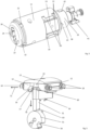
- the locking device 100 in the form of a lock cylinder, as is known to be used in mortise locks, in order to unlock a building door as a locking element or to be able to lock it by means of a bolt.
- the locking device 100 has a housing 101 with a recess in which a driver 103, which is designed as a locking lug, is rotatably arranged.
- the driver 103 is used to move a bolt in the locking or unlocking direction.
- the installation device 1 comprises a stator 10 in which a rotor 30 of the installation device 1 is inserted so that it can rotate about a rotor axis 35 which, for example, corresponds to the axis of rotation of the driver 103 .
- the rotor 30 On its front side 37 facing away from the driver 103, the rotor 30 comprises a key channel 36 for inserting a shank of a key 200.
- the key 200 carries an electronic locking code in the form of electronic data.
- the authorization of a user to unlock the door can be determined on the basis of the locking code.
- the key 200 is preferably designed without mechanical coding. Thus, it can only be determined on the basis of the electronic locking code whether the user has authorization or not.
- the key and the locking devices can be mechanically identical to each other.
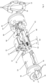
- FIG. 12 shows the closure device 100 partially disassembled.
- the housing 101 has, for example in both halves of the recess for the driver 103, openings 104 in the lower area, of which the opening on the right is provided with a reference number.
- the openings 104 here extend perpendicularly to the axis of rotation of the driver 103.
- the driver 103 has, for example, an inner contour that is non-circular in cross section, for example in the form of internal teeth, into which an insert 105 preferably engages in a form-fitting manner.
- the insert 105 has an outer contour that is preferably designed to complement the inner contour of the driver 103, here in the form of external teeth, so that the two parts 103, 105 are arranged in a rotationally fixed manner with respect to one another.
- a connecting section 38 of the installation device 1 protrudes into the insert 105 .
- a coupling part 41 is slidably arranged in a guide 42 in the connecting section 38 .
- the coupling part 41 is designed in several parts. Depending on the position of the coupling part 41 , the coupling part 41 can establish or release an operative connection between the rotor 30 and the driver 103 , in particular via the insert 105 .
- the coupling part 41 of the locking device 100 can engage in a non-illustrated inner contour of the insert 105 in a form-fitting manner.
- the guide 42 preferably forms a linear guide for the coupling part 41, so that the coupling part 41 is arranged to be guided along the rotor axis 35 of the rotor 30 so that it can be moved.
- the installation device 1 has a cover 14 with which the installation device 1 is pushed into an associated insertion opening 106 of the housing 101 .
- a fastening element 102 in the form of a screw is screwed through the recess 104 on the right here from the underside of the housing 101 and into an opening 21 on the left here in the casing 14 of the stator 10 and a stator body 11 of the stator 10 explained in more detail later.
- the screw 102 thus fixes the stator 10 in the housing 101.
- the key channel 36 for inserting the key 200 which is formed in a first rotor element 32 of the rotor 30, is also designated here.
- the stator body 11 is also designed as a type of sleeve, but has functional structures on the inside.
- the stator body 11 has a stator recess 19 into which a stator insert element 13 is inserted.
- Component elements 12 which will be explained in more detail later, are attached or arranged on a side of the stator insert element 13 that faces the interior of the stator body 11 .
- the component elements 12 are movably mounted on the stator insert element 13 and the stator body 11 .
- the component elements 12 remain in the rest of the stator 10 when the rotor 30 rotates.
- the component elements 12 are therefore designed as stator elements 12 .
- the rotor 30 comprises the first rotor element 32 and a second rotor element 33.
- the rotor 30 is freely rotatable in the stator body 11 of the stator 10 but is mounted stationary in the direction of its rotor axis 35 , which runs parallel to the insertion direction of the key 200 into the key channel 36 .
- the coupling part 41 is arranged on the second rotor element 33 of the rotor 30 of the installation device 1 in a rotationally fixed manner.
- Both rotor elements 32, 33 are reversibly detachable, for example by means of a screw 24, fastened to one another and arranged in the stator body 11 so as to be freely rotatable.
- the second rotor element 33 has the guide 42 in which the coupling part 41 engages and is thus arranged in a rotationally fixed manner with respect to the second rotor element 33 .
- the second rotor element 33 is inserted into the stator body 11 from a base side 23 of the stator 10, preferably without the first rotor element 32 during assembly.
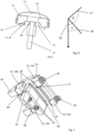
- FIG 4 shows the installation device 1 without the casing 14, the stator body 11 and the coupling part 41 in the partially dismantled state.
- An extension element 40 is intended to mechanically interact with the key 200 . If the key 200 is pushed into the key channel 36, it moves the extension element 40 axially or parallel to the rotor axis 35 upon contact.
- the key and thus the key channel 36 can have a small depth.
- the keyway 36 may be limited to the first rotor member 36 .
- the extension part 40 moves the coupling part 41 away from the rotor 30 in the direction of the driver 103 so that the coupling part 41 can engage the driver 103 in rotation.
- a passage 39 is provided in the connecting portion 38 for the extension member 40 to abut against the coupling member 41 .
- either the extension element 40 or the coupling part 41 can protrude through the passage 39 .
- a transmission element 44 here for example in the form of a coil, is provided in order to establish a data and/or energy transmission connection with the key 200.
- This makes it possible to read out electronic data, for example authentication information or an opening command, from the key 200 or to receive it from the key 200 .
- An electronic control device 53 is coupled to the coil in order to read out the data and, if necessary, evaluate it. If the control device 53 checks that the user of the key 200 is authorized to open the associated door and/or if the control device 53 has an opening command, an electromechanical actuator assembly 50 is activated.
- the actuator group 50 comprises an electromechanical actuator 52 here in the form of an electric motor, on the output shaft of which a blocking element 51 is arranged in a rotationally fixed manner. Blocking element 51 includes a recess 54, which will be explained in more detail later.
- a blocking element 31 is mounted in the second rotor element 33 so that it can move toward and away from the blocking element 51 , preferably perpendicular to the rotor axis 35 .
- the blocking element 31 In the first position shown here, the blocking element 31 is located in a blocking element recess 15 (see Fig. figure 5 ), which is formed by the stator insert element 13 and the stator elements 12. With this, the second rotor element 33 and thus the coupling part 41 are prevented from being rotated. The turning of the inserted key 200 to unlock the associated lock is blocked or prevented.
- a second position of the blocking element 31 (not shown), the blocking element 31 is disengaged from the blocking element recess 15 of the stator 10. This makes it possible to rotate the rotor 30 in the stator 10 and thus the driver 103.
- the blocking element 31 is held in place by at least one spring 34 (see Fig. figure 5 ), preferably several springs 34, are urged into the first position. In the embodiment of figure 5 several springs 34 are provided.
- Figures 5 to 7 show selected elements of the built-in device 1 4 . while showing figure 5 the arrangement of the blocking element 31 in relation to the blocking element 51 and the stator insert element 13 together with the stator elements 12.
- the blocking element 51 is between a release position in which the cutout 54 is opposite the blocking element 31 so that the blocking element 31 moves into the cutout 54 and locking positions in which the recess 54 does not oppose the locking member 31 so that the locking member 31 is prevented from entering the recess 54, rotatably.
- Blocking positions of the blocking element 51 are shown.
- the blocking element 31 is designed with a contact section 63 facing a blocking element 51 in order to be able to move into the recess 54 when the blocking element 51 is in the release position and the recess 54 is opposite the contact section 63 of the blocking element 31, in figure 5 i.e. pointing upwards. This makes it possible for the blocking element 31 to reach the second position.
- a first contact surface 16 of the stator elements 12 facing the blocking element 31 is designed in such a way that the blocking element 31 is pushed in the direction of the blocking element 51, i.e. into the second position, when the rotor 30 rotates further, in which the rotor 30 can rotate freely in relation to the stator 10 is.
- the first contact surface 16 is designed as an inclined surface that pushes the blocking element 31 into the second position.
- the first contact surface can be straight, convex or concave.
- the stator elements 12 are movably mounted on the stator insert element 13 and the stator body 11 between a first position and a second position.
- the stator elements 12 are urged into the first position by means of spring elements 18 .
- the spring elements 18 are mounted in the stator 10 .
- the movement of the stator elements 12 from the first position to the second position according to the direction of movement 71 is perpendicular to the direction of movement 70 of the blocking element 31 at the beginning of the movement.
- the locking element 31 When the rotor 30 is unlocked relative to the stator 10, the locking element 31 is initially located in the locking element recess 15. The locking element 31 is guided in the rotor 30 in this case. In addition, the blocking element 31 is in contact with the first contact surfaces 16 of the stator elements 12 . As a result, the blocking element 31 is centered. This position of the blocking element 31 is referred to as the rest position. In the rest position, the blocking element 31 is preferably arranged at a distance from the blocking element 51 .
- the control device 53 controls the actuator 52 .
- the actuator 52 designed as an electric motor rotates the blocking element 51 into the release position in which the recess 54 is opposite the blocking element 31 . If the rotor 30 is now started to rotate using the key 200, the blocking element 31 slides along one of the first contact surfaces 16 into the second position, in which the blocking element 31 in the recess 54 engages. Here, the springs 34 are stretched. The blocking element 31 moves in the direction of movement 70.
- the first contact surfaces 16 form an acute angle ⁇ with the direction of movement 70 of the blocking element 31 (see Fig. figure 8 ).
- stator elements 12 remain in the first position. This is made possible by the fact that the spring elements 18 exert a greater force on the stator element 12, along which the blocking element 31 slides, than the springs 34 exert on the blocking element 31.
- the rotor 30 is now freely rotatable.
- the locking element 31 slides along that of the first contact surfaces 16 into which the locking element 31 is rotated.
- the locking element 31 is surrounded by the first contact surfaces 16 in both directions of rotation, so that rotation in both directions when it contacts at least one of the first contact surfaces 16 allows the locking element 31 to move into the second position.
- the blocking element recess 15 is surrounded on both sides by at least a first stator element 12, 12a and a second stator element 12, 12b (see Fig. figure 7 ).
- the stator 10 has a second contact surface 17 which leaves the blocking element 31 in the first position.
- the second contact surface 17 is functionally used when the user is not authorized to unlock the door.
- the second contact surfaces are formed in the stator insert element 13 . If the blocking element 31 is in the rest position, the second contact surfaces 17 are spaced further away from the blocking element 31 than the first contact surfaces 16.
- the second contact surfaces 17 are preferably also inclined, but in the opposite direction to the first contact surfaces 16 in relation to the direction of movement 70 of the locking element 31.
- the second contact surfaces 17 thus form an obtuse angle ⁇ to the direction of movement 70 of the locking element 31 (see figure 8 ).
- the blocking element 31 seen along the axis of rotation of the blocking element 51 and/or the rotor axis 35, has a cross section which has the shape of a preferably symmetrical trapezium tapering in the direction of the blocking element 51.
- the legs of this trapezoid form head surfaces 60 outwardly in relation to the blocking element 31.
- the head surface 60 and the corresponding contact surface 17 are designed to be inclined relative to the direction of movement of the blocking element 31.
- the sequence is as follows.
- the locking element 31 is initially in the rest position.
- a key 200 without a locking authorization is inserted into the keyway 36 .
- the electronic data exchange shows that there is no authorization to unlock the door. Therefore, the actuator 52 is not activated and the blocking element 51 remains in a blocking position, in which the recess 54 does not face the locking element 31, as in FIG figure 4 and 5 shown. Rather, an outer circumference of the blocking element 51 lies opposite the blocking element 31 .
- the blocking element 31 If the rotor 30 is rotated, the blocking element 31 tries to slide along the first contact surface 16 . However, this does not succeed since the blocking element 31 stands on an outer circumference of the blocking element 31 . Thus, the blocking element 31 cannot be pushed into the second position against the force of the springs 34 .
- stator element 12 which is located in the direction of rotation of the blocking element 31 , is pushed back by the blocking element 31 against the force of the spring 18 until the blocking element 31 rests against the second contact surface 17 .
- the stator element 12 is now in the second position.
- the head surface 60 of the blocking element 31 comes into contact with the corresponding second contact surface 17 opposite one of the legs of the trapezium.
- stator element 12 or the stator elements 12 have been moved back in the direction of rotation against the force of a spring element 18 .
- the spring element 18 presses the stator element 12 against the locking element 31 as the rotor 30 rotates further.
- the contact surface 17 is designed in such a way that the contact surface 17 holds the blocking element 31 in the first position. Thus, the rotor 30 remains blocked by the blocking element 31 so that the door cannot be unlocked.
- Every second contact surface 17 corresponds to a respective head surface 60 of the blocking element 31 facing the head surface 60.
- the surface 60 and the corresponding contact surface 17 are designed in such a way that the contact surface 17 is located between the surface 60 and the blocking element 51 when the blocking element 31 is on the contact surface 17 is applied.
- the blocking element 31 slides away from the blocking element 51 counter to the direction of movement 70 . This is achieved by the slope of the second contact surface 17.
- the blocking element 31 can slide along with the head surface 60 on the second contact surface 17 .
- the blocking element 31 and the blocking element 51 can thus be spaced apart from one another when they are in contact with the second contact surface 17 .
- the forces that act on the blocking element 31 in the event of further attempted rotation of the rotor 30 are diverted into the second contact surface 17 .
- a contributing factor here is that the head surfaces 60 correspond to the second contact surfaces and the blocking element 31 thus lies flat against the second contact surface.
- this makes it possible to mount the blocking element 51 on one side.
- FIG 5 the blocking element recess is provided with the reference number 15 .
- 6 shows the arrangement of figure 5 Seen from an end face of the blocking element 31, only without blocking element 51.
- the stator elements 12 are in the second position.
- FIG 7 are the same elements as in figure 6 presented in a different perspective. Additionally are in figure 7 the spring elements 18 shown and on the left side a spring seat 65 of the stator 10 for receiving the spring elements 18, while the spring seat 65 is not shown on the right side.
- the blocking element 31 is surrounded by the second contact surfaces 17 in both directions of rotation, so that the rotation in both directions of rotation when it rests against one of the second contact surfaces 17 leaves the blocking element 31 in the first position.
- the first contact surfaces 16 are closer to the blocking element 31 than the second contact surfaces 17.
- the second contact surfaces 17 protrude more into the blocking element recess 15 than the first contact surfaces 16.
- the first and the second contact surfaces 16, 17 are arranged axially one behind the other in the direction of the rotor axis 35.
- four first contact surfaces 16 are provided, for example, with two first contact surfaces 16 being provided in each direction of rotation of the rotor 30 .
- two first stator elements 12a are provided on one side of the locking element recess 15 and two second stator elements 12b are provided on the other side of the locking element recess 15 .
- the blocking element 31 extends in the axial direction in relation to the rotor axis 35 in such a way that the blocking element 31 can come into contact with both the first contact surface 16 and the second contact surface 17 .
- the locking element 31 is formed in one piece.
- first contact sections 64 of the blocking element 31, which are used to contact the first contact surfaces 16, are rigidly connected to the head surfaces 60, which are used to contact the second contact surfaces 17.
- the top surfaces 60 serve here as second contact sections.
- the first and the second abutment sections 60, 64 are rigidly connected to the third abutment section 63 of the locking element, which serves to abut in the recess 54.
- the first contact section 64 is adapted to the first contact surface 16, ie the blocking element 31 in the first contact section 64, for example as an in Can be designed towards blocking element 51 widening trapezoid. As a result, the blocking element 31 can slide flatly along the first contact surface 16 .
- the four stator elements 12, for example, are outwardly delimited on one side by a guide surface 62 of the stator insert element 13 during the movement between the first and the second position.
- the stator elements 12 are delimited on the inside by a guide surface, not shown, of the stator body 11 .
- stator comprises a stator body 11 and a stator insert body 13, assembly of the built-in element 1 is facilitated.
- the shell 14 serves to fasten the stator insert body 13 in the stator body 11 .
- the first rotor element 32 has a larger diameter than the second rotor element 33.
- the stator elements 12 and the stator insert body 13 are arranged in the portion of the stator 10 which surrounds the second rotor element 33. Due to the small diameter of the second rotor element 33, it is possible to provide the first and the second system sections 16, 17 in the stator 10.
- a peripheral projection 43 of the second rotor element 33 serves as a stop for the second rotor element 33 on the stator 10.
- the projection 43 is preferably designed in one piece with the second rotor element 33. As a result, the second rotor element 33 is fixed axially towards the front side 37 .
- the first rotor element 32 can be inserted into the stator 10 from the front side 37 .
- the first rotor element 32 is fixed axially towards the driver 103 by an end face 66 facing the second rotor element 33 .
- the end surface 66 is in contact with an inner structure of the stator 10 , in particular of the stator body 11 .
- the second rotor element 33 can be inserted from the base 23 until the projection 43 rests against the base 23 .
- a locking element 61 is provided, which holds the rotor 30 in position in relation to the stator 10 (see Fig. 4 ).
- a rotation of the rotor 30 is inhibited by the latching element 61 in the stator in such a way that the blocking element 31 can assume the rest position.
- the latching element 61 is formed, for example, by means of a spring-loaded latching lug. i.e. the rotor 30 can overcome the detent 61 when rotating, so that the function of the rotor 30 is maintained.
- An annular projection 22 is formed by means of, in particular, half-shell-like parts whose inner surfaces 26 facing one another interact with the key 200 in the manner of a bayonet catch. The parts are inserted into a peripheral groove 45 of the first rotor element 32 . Outwardly projecting projections 25 of the annular Projection 22 fix the parts of the projection 22 in the stator body 11 in their relative position to each other and to the stator body 11.
- the annular projection 22 acts with the inserted key 200 preferably like a bayonet as a key withdrawal lock.
- the extension element 40 is angled in the example shown.
- a first part of the extension element 40 which is intended to interact with the key 200, runs radially further outward than a second part of the extension element 40, which is intended to interact with the coupling part 41.
- the second part can be arranged more centrally in order to be able to push the coupling part 41 better.
- the extension element 40 is designed to push the coupling part 41 but without being positively engaged with the coupling part 41 . This enables the extension element 40 to be of filigree design.
- the extension element 40 serves to return the blocking element 51 mechanically and/or magnetically from the release position to the blocking position.
- the extension element 40 can be moved back into a starting position when the key is removed.
- a movement of the blocking element 51 into the blocking position can be caused or permitted.
- a spring (not shown) can be tensioned during the movement of the blocking element 51 into the release position.
- FIG. 9 shows a further embodiment of the locking device according to the invention. While showing figure 9 a view that the figure 4 corresponds, ie .the shell 14 and the stator body 11 are not shown. In the following, only the differences from the first embodiment of the Figures 1 to 8 discussed.
- the first rotor element 32 comprises fastening means 67 and the second rotor element 33 has fastening means 68 corresponding thereto, which interlock positively so that the first rotor element 32 and the second rotor element 33 are fastened to one another in a rotationally fixed manner in the direction of rotation.
- the first and the second fastening means 67, 68 are designed as projections and corresponding recesses.
- contact elements are provided as the transmission device 44, which transmit data and/or electrical energy to the locking device 1 via electrical contact with the key 200.
- the contact elements 44 are attached to a housing 46 in a resilient manner.
- the housing 46 also serves to fasten the rotor elements 32, 33 to one another axially.
- the housing 46 includes a first latching element 47 which latches into the first rotor element 32 .
- the first rotor element 32 has an edge 78 .
- the housing 46 has a second latching element 48 which latches into the second rotor element 33 .
- the second rotor element 33 includes a not shown groove.
- the first rotor element 32 is axially fixed by a snap ring 72 in either direction along the axis of rotation.
- the snap ring 72 is arranged in a groove 73 of the first rotor element 33 .
- the latching element 61 designed here as a ball, is arranged in the stator 10 and engages in a recess 69 in the first rotor element 32 .
- the installation device 1 can also be used in other locking devices, for example in a half cylinder, a knob cylinder, a furniture cylinder or a padlock.
- the coupling part 41 is missing. Rather, locking devices according to the invention can be provided in which the driver 103 is rigidly attached to the rotor 30 .
- the driver 103 can also serve as a bolt itself, z. B. in a furniture lock.
- the driver 103 and the insert 105 can be formed in one piece with each other.
- stator insert element 13 and the stator body 11 can be designed in one piece. It is also conceivable that the shell 14 is missing and the stator directly in the
- Locking device housing 101 is fixed.
- the locking device 1 is not designed as a built-in device 1 .
- the stator 10 is designed as a locking device housing 101 .
- the rotor 30 can thus be designed to be pushed directly into a lock cylinder housing 101 .
- the locking device housing 101 then takes over the function of the stator 10.
- the blocking element 31 can also be mounted in the stator 10 so that it is pressed against the rotor 30 .
- the first and the second bearing surfaces 16, 17 are formed in the rotor.
- the contact surfaces 16, 17 are designed in such a way that the first contact surfaces 16 or the second contact surfaces 17 enclose the second contact surfaces 17 or the first contact surfaces 16, respectively. However, they can also be arranged differently relative to one another.
- the transmission device 44 can be in the form of a contact element for making electrical contact with the key, or in the second exemplary embodiment it can be in the form of contactless coils.
- the attachment can be done by locking means as in the second embodiment.
- the actuator moves the blocking element back into the blocking position. This can be provided in particular for knob cylinders.
- the blocking element 51 can alternatively be designed in the form of a plunger.
- a preferably bistable magnet can be used as an actuator.
- the plunger may be spring loaded in one direction, preferably away from the magnet.
- the rotor 30 does not have to have a plurality of rotor elements 32, 33. Nevertheless, the rotor 30 can have sections with different diameters.
Priority Applications (2)
| Application Number | Priority Date | Filing Date | Title |
|---|---|---|---|
| EP21212239.4A EP4191004A1 (fr) | 2021-12-03 | 2021-12-03 | Dispositif d'arrêt pour un élément de fermeture |
| PCT/EP2022/084201 WO2023099728A1 (fr) | 2021-12-03 | 2022-12-02 | Dispositif de verrouillage pour un élément de fermeture |
Applications Claiming Priority (1)
| Application Number | Priority Date | Filing Date | Title |
|---|---|---|---|
| EP21212239.4A EP4191004A1 (fr) | 2021-12-03 | 2021-12-03 | Dispositif d'arrêt pour un élément de fermeture |
Publications (1)
| Publication Number | Publication Date |
|---|---|
| EP4191004A1 true EP4191004A1 (fr) | 2023-06-07 |
Family
ID=78821241
Family Applications (1)
| Application Number | Title | Priority Date | Filing Date |
|---|---|---|---|
| EP21212239.4A Pending EP4191004A1 (fr) | 2021-12-03 | 2021-12-03 | Dispositif d'arrêt pour un élément de fermeture |
Country Status (2)
| Country | Link |
|---|---|
| EP (1) | EP4191004A1 (fr) |
| WO (1) | WO2023099728A1 (fr) |
Citations (6)
| Publication number | Priority date | Publication date | Assignee | Title |
|---|---|---|---|---|
| EP0324096A2 (fr) * | 1988-01-09 | 1989-07-19 | BKS GmbH | Serrure à cylindre, notamment cylindre pour serrure encastrée |
| EP1164238A1 (fr) * | 2000-06-15 | 2001-12-19 | Kaba Gege GmbH | Serrure cylindrique |
| WO2002088492A2 (fr) * | 2001-04-26 | 2002-11-07 | Kaba Gmbh | Cylindre de blocage |
| WO2003100199A1 (fr) * | 2002-05-27 | 2003-12-04 | Mul-T-Lock Technologies Ltd. | Verrou |
| FR2945065A1 (fr) * | 2009-05-03 | 2010-11-05 | Cogelec | Serrure electonique |
| EP1914368B1 (fr) | 2006-10-18 | 2018-06-13 | ISEO SERRATURE S.p.A. | Serrure électronique pour portes et fenêtres |
-
2021
- 2021-12-03 EP EP21212239.4A patent/EP4191004A1/fr active Pending
-
2022
- 2022-12-02 WO PCT/EP2022/084201 patent/WO2023099728A1/fr unknown
Patent Citations (6)
| Publication number | Priority date | Publication date | Assignee | Title |
|---|---|---|---|---|
| EP0324096A2 (fr) * | 1988-01-09 | 1989-07-19 | BKS GmbH | Serrure à cylindre, notamment cylindre pour serrure encastrée |
| EP1164238A1 (fr) * | 2000-06-15 | 2001-12-19 | Kaba Gege GmbH | Serrure cylindrique |
| WO2002088492A2 (fr) * | 2001-04-26 | 2002-11-07 | Kaba Gmbh | Cylindre de blocage |
| WO2003100199A1 (fr) * | 2002-05-27 | 2003-12-04 | Mul-T-Lock Technologies Ltd. | Verrou |
| EP1914368B1 (fr) | 2006-10-18 | 2018-06-13 | ISEO SERRATURE S.p.A. | Serrure électronique pour portes et fenêtres |
| FR2945065A1 (fr) * | 2009-05-03 | 2010-11-05 | Cogelec | Serrure electonique |
Also Published As
| Publication number | Publication date |
|---|---|
| WO2023099728A1 (fr) | 2023-06-08 |
Similar Documents
| Publication | Publication Date | Title |
|---|---|---|
| EP1636454B1 (fr) | Barillet electromagnetique | |
| EP1574643B1 (fr) | Cylindre de serrure électromécanique | |
| EP1214491B1 (fr) | Unite de verrouillage pour une serrure a barillet | |
| EP2436858B1 (fr) | Cylindre de fermeture pour un verrou | |
| EP3207197B1 (fr) | Élément d'actionnement pour une serrure à palastre | |
| DE19930054C5 (de) | Elektromechanisches Schließsystem | |
| DE60105778T2 (de) | Schloss | |
| EP0819810B1 (fr) | Ferrure pour une serrure | |
| DE102008063061A1 (de) | Betätigungsvorrichtung für ein elektronisches Türschloß | |
| DE19604442A1 (de) | Sicherheitsvorrichtung für elektronische Schlösser | |
| EP1135284A1 (fr) | Systeme de fermeture, notamment pour automobiles | |
| DE102007011554B4 (de) | Koppeleinheit für elektronische Schließ-Systeme | |
| EP4191004A1 (fr) | Dispositif d'arrêt pour un élément de fermeture | |
| EP1267020B1 (fr) | Dispositif de verrouillage | |
| DE102004063126B3 (de) | Elektromechanisches Schließsystem | |
| EP1323880A2 (fr) | Serrure cylindrique, notamment pour serrure encastrée | |
| WO2023099747A1 (fr) | Dispositif de blocage destiné à un élément de fermeture ou à un élément de commutation | |
| EP4191000A1 (fr) | Dispositif de verrouillage électromécanique | |
| EP4191003A1 (fr) | Dispositif de verrouillage électromécanique | |
| EP4191005A1 (fr) | Dispositif électromécanique d'installation permettant d'insérer dans un dispositif de fermeture de type cylindre de fermeture | |
| EP3535463B1 (fr) | Unité de fermeture pour un véhicule automobile | |
| WO2023099729A1 (fr) | Dispositif de verrouillage doté d'un stator, d'un rotor et d'un dispositif anti-retrait | |
| DE102022114938B3 (de) | Riegelschlossanordnung und Set aus Schließzylinder und Befestigungszwischenstück | |
| EP1356177A1 (fr) | Dispositif de fermeture a commande electronique | |
| AT524794B1 (de) | Zylinderschloss |
Legal Events
| Date | Code | Title | Description |
|---|---|---|---|
| PUAI | Public reference made under article 153(3) epc to a published international application that has entered the european phase |
Free format text: ORIGINAL CODE: 0009012 |
|
| STAA | Information on the status of an ep patent application or granted ep patent |
Free format text: STATUS: THE APPLICATION HAS BEEN PUBLISHED |
|
| AK | Designated contracting states |
Kind code of ref document: A1 Designated state(s): AL AT BE BG CH CY CZ DE DK EE ES FI FR GB GR HR HU IE IS IT LI LT LU LV MC MK MT NL NO PL PT RO RS SE SI SK SM TR |
|
| STAA | Information on the status of an ep patent application or granted ep patent |
Free format text: STATUS: REQUEST FOR EXAMINATION WAS MADE |
|
| 17P | Request for examination filed |
Effective date: 20231204 |
|
| RBV | Designated contracting states (corrected) |
Designated state(s): AL AT BE BG CH CY CZ DE DK EE ES FI FR GB GR HR HU IE IS IT LI LT LU LV MC MK MT NL NO PL PT RO RS SE SI SK SM TR |
|
| RIC1 | Information provided on ipc code assigned before grant |
Ipc: E05B 13/00 20060101ALN20240201BHEP Ipc: E05B 9/04 20060101ALI20240201BHEP Ipc: E05B 47/00 20060101ALI20240201BHEP Ipc: E05B 47/06 20060101AFI20240201BHEP |
|
| GRAP | Despatch of communication of intention to grant a patent |
Free format text: ORIGINAL CODE: EPIDOSNIGR1 |
|
| STAA | Information on the status of an ep patent application or granted ep patent |
Free format text: STATUS: GRANT OF PATENT IS INTENDED |
|
| GRAS | Grant fee paid |
Free format text: ORIGINAL CODE: EPIDOSNIGR3 |
|
| RIC1 | Information provided on ipc code assigned before grant |
Ipc: E05B 13/00 20060101ALN20240306BHEP Ipc: E05B 9/04 20060101ALI20240306BHEP Ipc: E05B 47/00 20060101ALI20240306BHEP Ipc: E05B 47/06 20060101AFI20240306BHEP |
|
| GRAA | (expected) grant |
Free format text: ORIGINAL CODE: 0009210 |
|
| STAA | Information on the status of an ep patent application or granted ep patent |
Free format text: STATUS: THE PATENT HAS BEEN GRANTED |
|
| INTG | Intention to grant announced |
Effective date: 20240319 |