EP4188043B1 - Procédé d'assemblage d'un ensemble de refroidissement de liquide d'une famille d'ensembles de refroidissement de liquide - Google Patents
Procédé d'assemblage d'un ensemble de refroidissement de liquide d'une famille d'ensembles de refroidissement de liquide Download PDFInfo
- Publication number
- EP4188043B1 EP4188043B1 EP21306655.8A EP21306655A EP4188043B1 EP 4188043 B1 EP4188043 B1 EP 4188043B1 EP 21306655 A EP21306655 A EP 21306655A EP 4188043 B1 EP4188043 B1 EP 4188043B1
- Authority
- EP
- European Patent Office
- Prior art keywords
- liquid cooling
- thermal contact
- base
- contact surface
- heat spreading
- Prior art date
- Legal status (The legal status is an assumption and is not a legal conclusion. Google has not performed a legal analysis and makes no representation as to the accuracy of the status listed.)
- Active
Links
Images


Classifications
-
- H—ELECTRICITY
- H05—ELECTRIC TECHNIQUES NOT OTHERWISE PROVIDED FOR
- H05K—PRINTED CIRCUITS; CASINGS OR CONSTRUCTIONAL DETAILS OF ELECTRIC APPARATUS; MANUFACTURE OF ASSEMBLAGES OF ELECTRICAL COMPONENTS
- H05K7/00—Constructional details common to different types of electric apparatus
- H05K7/20—Modifications to facilitate cooling, ventilating, or heating
- H05K7/20218—Modifications to facilitate cooling, ventilating, or heating using a liquid coolant without phase change in electronic enclosures
- H05K7/20254—Cold plates transferring heat from heat source to coolant
-
- H—ELECTRICITY
- H05—ELECTRIC TECHNIQUES NOT OTHERWISE PROVIDED FOR
- H05K—PRINTED CIRCUITS; CASINGS OR CONSTRUCTIONAL DETAILS OF ELECTRIC APPARATUS; MANUFACTURE OF ASSEMBLAGES OF ELECTRICAL COMPONENTS
- H05K7/00—Constructional details common to different types of electric apparatus
- H05K7/20—Modifications to facilitate cooling, ventilating, or heating
- H05K7/2029—Modifications to facilitate cooling, ventilating, or heating using a liquid coolant with phase change in electronic enclosures
- H05K7/20327—Accessories for moving fluid, for connecting fluid conduits, for distributing fluid or for preventing leakage, e.g. pumps, tanks or manifolds
-
- F—MECHANICAL ENGINEERING; LIGHTING; HEATING; WEAPONS; BLASTING
- F28—HEAT EXCHANGE IN GENERAL
- F28D—HEAT-EXCHANGE APPARATUS, NOT PROVIDED FOR IN ANOTHER SUBCLASS, IN WHICH THE HEAT-EXCHANGE MEDIA DO NOT COME INTO DIRECT CONTACT
- F28D1/00—Heat-exchange apparatus having stationary conduit assemblies for one heat-exchange medium only, the media being in contact with different sides of the conduit wall, in which the other heat-exchange medium is a large body of fluid, e.g. domestic or motor car radiators
- F28D1/02—Heat-exchange apparatus having stationary conduit assemblies for one heat-exchange medium only, the media being in contact with different sides of the conduit wall, in which the other heat-exchange medium is a large body of fluid, e.g. domestic or motor car radiators with heat-exchange conduits immersed in the body of fluid
- F28D1/03—Heat-exchange apparatus having stationary conduit assemblies for one heat-exchange medium only, the media being in contact with different sides of the conduit wall, in which the other heat-exchange medium is a large body of fluid, e.g. domestic or motor car radiators with heat-exchange conduits immersed in the body of fluid with plate-like or laminated conduits
- F28D1/0308—Heat-exchange apparatus having stationary conduit assemblies for one heat-exchange medium only, the media being in contact with different sides of the conduit wall, in which the other heat-exchange medium is a large body of fluid, e.g. domestic or motor car radiators with heat-exchange conduits immersed in the body of fluid with plate-like or laminated conduits the conduits being formed by paired plates touching each other
- F28D1/035—Heat-exchange apparatus having stationary conduit assemblies for one heat-exchange medium only, the media being in contact with different sides of the conduit wall, in which the other heat-exchange medium is a large body of fluid, e.g. domestic or motor car radiators with heat-exchange conduits immersed in the body of fluid with plate-like or laminated conduits the conduits being formed by paired plates touching each other with U-flow or serpentine-flow inside the conduits
-
- F—MECHANICAL ENGINEERING; LIGHTING; HEATING; WEAPONS; BLASTING
- F28—HEAT EXCHANGE IN GENERAL
- F28F—DETAILS OF HEAT-EXCHANGE AND HEAT-TRANSFER APPARATUS, OF GENERAL APPLICATION
- F28F3/00—Plate-like or laminated elements; Assemblies of plate-like or laminated elements
- F28F3/12—Elements constructed in the shape of a hollow panel, e.g. with channels
-
- G—PHYSICS
- G06—COMPUTING OR CALCULATING; COUNTING
- G06F—ELECTRIC DIGITAL DATA PROCESSING
- G06F1/00—Details not covered by groups G06F3/00 - G06F13/00 and G06F21/00
- G06F1/16—Constructional details or arrangements
- G06F1/20—Cooling means
-
- H—ELECTRICITY
- H05—ELECTRIC TECHNIQUES NOT OTHERWISE PROVIDED FOR
- H05K—PRINTED CIRCUITS; CASINGS OR CONSTRUCTIONAL DETAILS OF ELECTRIC APPARATUS; MANUFACTURE OF ASSEMBLAGES OF ELECTRICAL COMPONENTS
- H05K7/00—Constructional details common to different types of electric apparatus
- H05K7/20—Modifications to facilitate cooling, ventilating, or heating
- H05K7/2029—Modifications to facilitate cooling, ventilating, or heating using a liquid coolant with phase change in electronic enclosures
- H05K7/20318—Condensers
-
- H—ELECTRICITY
- H05—ELECTRIC TECHNIQUES NOT OTHERWISE PROVIDED FOR
- H05K—PRINTED CIRCUITS; CASINGS OR CONSTRUCTIONAL DETAILS OF ELECTRIC APPARATUS; MANUFACTURE OF ASSEMBLAGES OF ELECTRICAL COMPONENTS
- H05K7/00—Constructional details common to different types of electric apparatus
- H05K7/20—Modifications to facilitate cooling, ventilating, or heating
- H05K7/2029—Modifications to facilitate cooling, ventilating, or heating using a liquid coolant with phase change in electronic enclosures
- H05K7/20336—Heat pipes, e.g. wicks or capillary pumps
-
- H—ELECTRICITY
- H05—ELECTRIC TECHNIQUES NOT OTHERWISE PROVIDED FOR
- H05K—PRINTED CIRCUITS; CASINGS OR CONSTRUCTIONAL DETAILS OF ELECTRIC APPARATUS; MANUFACTURE OF ASSEMBLAGES OF ELECTRICAL COMPONENTS
- H05K7/00—Constructional details common to different types of electric apparatus
- H05K7/20—Modifications to facilitate cooling, ventilating, or heating
- H05K7/2039—Modifications to facilitate cooling, ventilating, or heating characterised by the heat transfer by conduction from the heat generating element to a dissipating body
- H05K7/20509—Multiple-component heat spreaders; Multi-component heat-conducting support plates; Multi-component non-closed heat-conducting structures
-
- H—ELECTRICITY
- H10—SEMICONDUCTOR DEVICES; ELECTRIC SOLID-STATE DEVICES NOT OTHERWISE PROVIDED FOR
- H10W—GENERIC PACKAGES, INTERCONNECTIONS, CONNECTORS OR OTHER CONSTRUCTIONAL DETAILS OF DEVICES COVERED BY CLASS H10
- H10W40/00—Arrangements for thermal protection or thermal control
- H10W40/01—Manufacture or treatment
- H10W40/03—Manufacture or treatment of arrangements for cooling
- H10W40/037—Assembling together parts thereof
-
- H—ELECTRICITY
- H10—SEMICONDUCTOR DEVICES; ELECTRIC SOLID-STATE DEVICES NOT OTHERWISE PROVIDED FOR
- H10W—GENERIC PACKAGES, INTERCONNECTIONS, CONNECTORS OR OTHER CONSTRUCTIONAL DETAILS OF DEVICES COVERED BY CLASS H10
- H10W40/00—Arrangements for thermal protection or thermal control
- H10W40/40—Arrangements for thermal protection or thermal control involving heat exchange by flowing fluids
- H10W40/47—Arrangements for thermal protection or thermal control involving heat exchange by flowing fluids by flowing liquids, e.g. forced water cooling
-
- F—MECHANICAL ENGINEERING; LIGHTING; HEATING; WEAPONS; BLASTING
- F28—HEAT EXCHANGE IN GENERAL
- F28D—HEAT-EXCHANGE APPARATUS, NOT PROVIDED FOR IN ANOTHER SUBCLASS, IN WHICH THE HEAT-EXCHANGE MEDIA DO NOT COME INTO DIRECT CONTACT
- F28D21/00—Heat-exchange apparatus not covered by any of the groups F28D1/00 - F28D20/00
- F28D2021/0019—Other heat exchangers for particular applications; Heat exchange systems not otherwise provided for
- F28D2021/0028—Other heat exchangers for particular applications; Heat exchange systems not otherwise provided for for cooling heat generating elements, e.g. for cooling electronic components or electric devices
- F28D2021/0029—Heat sinks
-
- G—PHYSICS
- G06—COMPUTING OR CALCULATING; COUNTING
- G06F—ELECTRIC DIGITAL DATA PROCESSING
- G06F2200/00—Indexing scheme relating to G06F1/04 - G06F1/32
- G06F2200/20—Indexing scheme relating to G06F1/20
- G06F2200/201—Cooling arrangements using cooling fluid
-
- Y—GENERAL TAGGING OF NEW TECHNOLOGICAL DEVELOPMENTS; GENERAL TAGGING OF CROSS-SECTIONAL TECHNOLOGIES SPANNING OVER SEVERAL SECTIONS OF THE IPC; TECHNICAL SUBJECTS COVERED BY FORMER USPC CROSS-REFERENCE ART COLLECTIONS [XRACs] AND DIGESTS
- Y02—TECHNOLOGIES OR APPLICATIONS FOR MITIGATION OR ADAPTATION AGAINST CLIMATE CHANGE
- Y02E—REDUCTION OF GREENHOUSE GAS [GHG] EMISSIONS, RELATED TO ENERGY GENERATION, TRANSMISSION OR DISTRIBUTION
- Y02E60/00—Enabling technologies; Technologies with a potential or indirect contribution to GHG emissions mitigation
- Y02E60/14—Thermal energy storage
Definitions
- the present technology relates to liquid cooling assemblies and methods and systems for assembly thereof.
- Heat dissipation is an important consideration for computer systems.
- a processor also referred to as central processing unit (CPU)
- CPU central processing unit
- Similar considerations arise for systems other than computer systems (e.g., power management systems).
- different types of cooling solutions are implemented to promote heat dissipation from heat-generating electronic components, with the objective being to collect and conduct thermal energy away from these heat-generating electronic components.
- multiple electronic systems e.g., servers, networking equipment, power equipment
- such cooling solutions may be particularly important.
- a cooling solution is a heat sink which relies on a heat transfer medium (e.g., a gas or liquid) to carry away the heat generated by a heat-generating electronic component.
- a liquid cooling block (sometimes referred to as a "water block"), which is a liquid cooling heat sink, can be thermally coupled to a heat-generating electronic component and water (or other liquid) is made to flow through a conduit in the liquid cooling block to absorb heat from the heat-generating electronic component. As water flows out of the liquid cooling block, so does the thermal energy collected thereby.
- EP620741 A1 discloses a thermal transfer device has a body and a fluid conduit defined in the body.
- the body has a thermal transfer surface configured to be placed in contact with a target component.
- the fluid conduit is configured for conveying fluid through the body and is thermally coupled to the thermal transfer surface.
- a method for assembling a liquid cooling assembly of a family of liquid cooling assemblies including at least a first liquid cooling assembly and a second liquid cooling assembly, the method comprising: providing a plurality of liquid cooling blocks, each of the liquid cooling blocks defining an internal fluid conduit for circulation of cooling fluid therethrough, each of the liquid cooling blocks having a block thermal contact surface, the block thermal contact surface of each of the liquid cooling blocks having a same surface area; providing a first heat spreading base having a first thermal contact surface on a lower side of the first heat spreading base, the first thermal contact surface being configured to be in thermal contact with a first heat-generating electronic component, the first heat spreading base defining at least one first pocket on an upper side thereof; providing a second heat spreading base having a second thermal contact surface on a lower side of the second heat spreading base, the second thermal contact surface being configured to be in thermal contact with a second heat-generating electronic component, the second heat spreading base defining a plurality of second pockets on an upper side thereof, the second thermal contact
- each of the liquid cooling blocks has a lower portion defining the block thermal contact surface thereof; when assembling the first liquid cooling assembly, inserting the selected at least one liquid cooling block comprises inserting the lower portion of the selected at least one liquid cooling block into the at least one first pocket; and when assembling the second liquid cooling assembly, inserting the selected at least two liquid cooling blocks comprises inserting the lower portions of the selected at least two liquid cooling blocks into the second pockets.
- the method further comprises: when assembling the first liquid cooling assembly, applying a thermal interface material on at least one of: (i) each upper base surface defining the at least one first pocket of the first heat spreading base, and (ii) the block thermal contact surface of each of the selected at least one liquid cooling block; and when assembling the second cooling assembly, applying a thermal interface material on at least one of: (i) each upper base surface defining a corresponding one of the second pockets of the second heat spreading base, and (ii) the block thermal contact surface of each of the selected at least two liquid cooling blocks.
- the at least one first pocket and the second pockets are sized to closely fit part of each of the liquid cooling blocks.
- the first heat spreading base is generally square; and the second heat spreading base is generally rectangular.
- the at least one first pocket is a single first pocket.
- the plurality of second pockets is two second pockets.
- the liquid cooling blocks are identical to one another.
- each liquid cooling block comprises a base and a cover connected thereto, the internal fluid conduit of each liquid cooling block being defined between the base and the cover thereof.
- the surface area of the second thermal contact surface is at least two times greater than the surface area of the first thermal contact surface.
- a system for assembling a liquid cooling assembly of a family of liquid cooling assemblies including at least a first liquid cooling assembly and a second liquid cooling assembly, the system comprising: a plurality of liquid cooling blocks, each of the liquid cooling blocks defining an internal fluid conduit for circulation of cooling liquid therethrough, each of the liquid cooling blocks having a block thermal contact surface, the block thermal contact surfaces of the liquid cooling blocks having a same surface area; a first heat spreading base having a first thermal contact surface on a lower side of the first heat spreading base, the first thermal contact surface being configured to be in thermal contact with a first heat-generating electronic component, the first heat spreading base defining at least one first pocket on an upper side thereof; a second heat spreading base having a second thermal contact surface on a lower side of the second heat spreading base, the second thermal contact surface being configured to be in thermal contact with a second heat-generating electronic component, the second heat spreading base defining a plurality of second pockets on an upper side thereof, the second thermal contact surface having a surface
- each of the liquid cooling blocks comprises a lower portion defining the block thermal contact surface thereof and an upper portion, a periphery of the lower portion being smaller than a periphery of the upper portion; when the first liquid cooling assembly is assembled, the lower portion of each of the at least one liquid cooling block is received in the respective one of the at least one first pocket; and when the second liquid cooling assembly is assembled, the lower portion of each of the at least two liquid cooling blocks is received within a respective one of the second pockets.
- the at least one first pocket and the second pockets are sized to closely fit part of each of the liquid cooling blocks.
- the at least one first pocket is a single first pocket.
- the surface area of the second thermal contact surface is at least two times greater than the surface area of the first thermal contact surface.
- Embodiments of the present technology each have at least one of the above-mentioned object and/or aspects, but do not necessarily have all of them. It should be understood that some aspects of the present technology that have resulted from attempting to attain the above-mentioned object may not satisfy this object and/or may satisfy other objects not specifically recited herein.
- Figs. 1 and 8 illustrate two different liquid cooling assemblies 100, 200 in accordance with an embodiment of the present technology.
- the liquid cooling assemblies 100, 200 are configured for cooling respective heat-generating electronic components 50, 50' (illustrated in Figs. 2 and 9 respectively).
- each of the heat-generating electronic components 50, 50' is a central processing unit (CPU).
- CPU central processing unit
- each heat-generating electronic component 50, 50' may be part of a respective server operating within a data center.
- the heat-generating electronic components 50, 50' generate a significant amount of heat and, as is known, can benefit from cooling.
- each of the heat-generating electronic components 50, 50' could be any other suitable heat-generating electronic component (e.g., a graphics processing unit (GPU)).
- the heat-generating electronic components 50, 50' may be different types of heat-generating electronic components from one another (e.g., a CPU and a GPU respectively).
- each liquid cooling assembly 100, 200 of the family of liquid cooling assemblies includes a common model of liquid cooling block 10 having an internal fluid conduit to circulate a cooling fluid therethrough.
- the liquid cooling block 10 can be used in the assembly of either of the liquid cooling assemblies 100, 200. This may allow the liquid cooling assemblies 100, 200 of the same family to be used for cooling different heat-generating electronic components 50, 50' without having to produce a different model of liquid cooling block altogether to accommodate either one of the heat-generating electronic components 50, 50'.
- liquid cooling block 10 will now be described with reference to Figs. 1 to 3 and 5 to 7 in which the liquid cooling block 10 is illustrated forming part of the liquid cooling assembly 100.
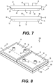
- the liquid cooling block 10 has a base 12 and a cover 14 which are connected to one another to form the liquid cooling block 10.
- the base 12 and the cover 14 define an internal fluid conduit 15 (schematically illustrated in Fig. 5 ) within which a cooling fluid is circulated to absorb heat from the heat-generating electronic component (50 or 50').
- the internal fluid conduit 15 extends from an inlet 17 to an outlet 19 of the liquid cooling block 10.
- the cooling fluid circulated through the internal fluid conduit 15 is demineralized water.
- the cooling fluid may be any other suitable cooling fluid (e.g., a refrigerant) in other embodiments.
- the cooling fluid may be capable of two-phase flow such that the cooling fluid can change phases from liquid to gas and vice-versa based on a temperature thereof.
- the cooling fluid circulating within the liquid cooling block 10 will thus, at some point, be in the liquid phase, however the cooling fluid may not necessarily be in liquid phase throughout (e.g., the cooling fluid may evaporate from liquid to gas when its temperature reaches a certain value).
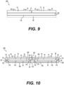
- the base 12 has a lower portion 16 and an upper portion 18 disposed above the lower portion 16.
- the lower portion 16 has a periphery that is smaller than a periphery of the upper portion 18 and, as such, the upper portion 18 forms a peripheral shoulder 24 that extends outwardly from an upper end of the lower portion 16.
- the peripheral shoulder 24 defines a shoulder surface 26 on a lower side 20 of the base 12.
- the lower portion 16 is also positioned generally centrally relative to the upper portion 18. In this embodiment, the lower portion 16 is generally square and thus has four outer surfaces 29, one of which is shown in Fig. 7 .
- the lower portion 16 defines a thermal contact surface 22 of the liquid cooling block 10, the thermal contact surface 22 being disposed on the lower side 20 of the base 12.
- the thermal contact surface 22 is the surface of the base 12 through which heat is primarily transferred to the liquid cooling block 10. As such, in use, the thermal contact surface 22 is placed in thermal contact with another surface from which heat is to be absorbed.
- the thermal contact surface 22 is parallel to the shoulder surface 26 and is offset therefrom in a height direction of the liquid cooling block 10, the height direction of the liquid cooling block 10 being normal to the thermal contact surface 22.
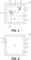
- the upper portion 18 of the base 12 defines an upper base surface 28 disposed on and accessible from an upper side 21 of the base 12.
- the upper portion 18 also includes a retaining lip section 30 which extends upward from the upper base surface 28 and is disposed peripherally around the upper base surface 28.
- a pocket 32 is defined by the upper base surface 28 and the retaining lip section 30.
- the pocket 32 is shaped and dimensioned to at least partly receive the cover 14 therein.
- the pocket 32 is generally square as defined by the square shape of the retaining lip section 30.
- the upper base surface 28 defines a channel 34 that forms in part the internal fluid conduit 15 of the liquid cooling block 10.
- the channel 34 establishes a path of the internal fluid conduit 15 and thus guides the cooling fluid circulating therein through the liquid cooling block 10 from the inlet 17 to the outlet 19 of the liquid cooling block 10.
- the channel 34 may have any suitable shape in different embodiments.
- the channel 34 may be shaped to define in part a serpentine path from the inlet 17 to the outlet 19. Examples of different shapes that the channel 34 could have are described in greater detail in European Patent Application 18315027.5, filed September 4, 2018 , the entirety of which is incorporated by reference herein.
- the base 12 is a single-piece component made integrally such that the base 12 is formed from a continuous material.
- the base 12 may also be referred to as a "base body".
- the base 12 is formed at least in part by punching. More specifically, a punch 300 is pressed onto the material of the base 12 from the upper side 21 which, in an initial condition, is a flat plate member. As such, the punch 300 deforms the material of the flat plate member to form the above-described shape of the base 12, namely including the lower portion 16, the upper portion 18 and the pocket 32. Forming the base 12 by punching can be cost-efficient, particularly when repeatably producing many such components, and notably because the height of the raw flat plate member is lower than the height of the formed base 12.
- the base 12 may be formed differently in other embodiments.
- the cover 14 is a plate member that is generally planar and shaped to be received within the pocket 32.
- the cover 14 has an upper (outer) surface 36 and a lower (inner) surface 38 on opposite sides of the cover 14.
- the cover 14 defines an inlet opening 23 and an outlet opening 25 which extend from the upper surface 36 to the lower surface 38.
- the inlet and outlet openings 23, 25 correspond to the inlet 17 and the outlet 19 of the liquid cooling block 10 respectively.
- cooling fluid is respectively fed into and discharged from the internal fluid conduit 15 through the inlet opening 23 and the outlet opening 25 of the cover 14.
- Inlet and outlet ducts 40, 42 are connected to the cover 14 at the inlet and outlet openings 23, 25 respectively to fluidly connect the internal fluid conduit 15 to an external cooling fluid source.
- the external cooling fluid source may comprise a circuit of cooling equipment including one or more dry coolers installed outside of the data center. As such, during use, in this embodiment, cooling fluid is continuously recirculated between the external cooling fluid source and the liquid cooling block 10.
- the cover 14 is received in the pocket 32 of the base 12 with the lower surface 36 of the cover 14 facing the upper base surface 28.
- the lower surface 36 is placed in contact with the upper base surface 28.
- the internal fluid conduit 15 of the liquid cooling block 10 is thus defined by the lower surface 36 of the cover 14 and the channel 34 of the base 12.
- the cover 14 could define a channel in the lower surface 36 complementary to the channel 34 of the base 12.
- the channel 34 could be omitted from the base 12 and the cover 14 could define the channel instead.
- the cover 14 has a thickness approximately equal to a height of the retaining lip section 30 such that, when the cover 14 is in place in the pocket 32, an upper (outer) surface 38 of the cover 14 is generally flush with the upper surface of the retaining lip section 30.
- the cover 14 is welded to the base 12 along a periphery of the cover 14.
- the cover 14 may be laser welded to the base 12. The relatively small periphery of the cover 14 is helpful for limiting a temperature increase of the cover 14 and the base 12 during welding.
- welding the cover 14 to the base 12 generally increases the temperature of the cover 14 and the base 12 and therefore, providing a cover with a greater periphery would increase the amount of time to which the cover 14 and the base 12 are exposed to increased temperatures which could result in deformation of the cover 14 and/or the base 12.
- the liquid cooling assembly 100 includes the liquid cooling block 10 as previously described and a heat spreading base 60 that at least partly receives the liquid cooling block 10.
- the heat spreading base 60 is configured to be positioned between the liquid cooling block 10 and the heat-generating electronic component 50 such that, in use, heat is transferred from the heat-generating electronic component 50 to the heat spreading base 60 and subsequently to the liquid cooling block 10.
- the heat spreading base 60 has a base body 62 which has substantially the same configuration as the base 12 of the liquid cooling block 10.
- the base body 62 has a lower portion 64 and an upper portion 66 disposed above the lower portion 64.
- the lower portion 64 has a periphery that is smaller than a periphery of the upper portion 66 and, as such, the upper portion 66 forms a peripheral shoulder 72 that extends outwardly from an upper end of the lower portion 64.
- the peripheral shoulder 72 defines a shoulder surface 74 on a lower side 68 of the base body 62.
- the lower portion 64 is also positioned generally centrally relative to the upper portion 66. In this embodiment, the lower portion 64 is generally square.
- the lower portion 64 defines a thermal contact surface 70 of the heat spreading base 60, the thermal contact surface 70 being disposed on the lower side 68 of the base body 62. As shown in Fig. 2 , the thermal contact surface 70 is configured to be placed in thermal contact with the heat-generating electronic component 50. As such, the thermal contact surface 70 is the surface of the heat spreading base 60 through which heat is primarily transferred to the heat spreading base 60.
- the upper portion 66 of the base body 62 defines an upper base surface 76 accessible from an upper side 69 of the base body 62.
- the upper portion 66 also includes a retaining lip section 78 which extends upward from the upper base surface 76 and is disposed peripherally around the base surface 76.
- a pocket 80 is defined by the upper base surface 76 and the retaining lip section 78.
- the pocket 80 is shaped and dimensioned to at least partly receive the base 12 of the liquid cooling block 10.
- the pocket 80 is generally square to correspond to the square shape of the lower portion 16 of the base 12 of the liquid cooling block 10.
- the retaining lip section 78 has four inner surfaces 79 forming the square shape of the pocket 80.
- the upper base surface 76 does not define a channel like the channel 34 of the base 12.
- the base body 62 is identical to the base 12 of the liquid cooling block 10 with the exception of the channel 34 which is omitted from the base body 62.
- the base body 62 is formed in the same manner as the base 12.
- the base body 62 is also formed by punching.
- the liquid cooling assembly 100 is formed by mating the liquid cooling block 10 with the heat spreading base 60. More specifically, the lower portion 16 of the liquid cooling block 10 is inserted into the pocket 80 defined by the heat spreading base 60. To that end, the pocket 80 is shaped and dimensioned such that, when the lower portion 16 is inserted therein, the inner surfaces 79 of the retaining lip section 78 defining the pocket 80 and the outer surfaces 29 of the lower portion 16 are in a close fit such that the lower portion 16 is insertable into and removable from the pocket 80 by hand.
- the retaining lip section 78 of the heat spreading base 60 thus surrounds the lower portion 16 of the liquid cooling block 10 and thereby limits movement of the liquid cooling block 10 relative to the heat spreading base 60 along horizontal directions (e.g., frontwardly, rearwardly and laterally).
- the thermal contact surface 22 of the liquid cooling block 10 is in contact with the upper base surface 76 of the heat spreading base 60.
- heat is transferred from the heat-generating electronic component 50 to the heat spreading base 60 through the thermal contact surface 70 of the heat spreading base 60, with a thermal interface material disposed between the thermal contact surface 70 and the heat-generating electronic component 50.
- heat is transferred, at least primarily, from the heat spreading base 60 to the liquid cooling block 10 via the upper base surface 76 of the heat spreading base 60 and the thermal contact surface 22 of the liquid cooling block 10 which are mated with one another.
- the heat transferred to the liquid cooling block 10 is then absorbed by the cooling fluid circulating in the internal fluid conduit 15.
- the heated cooling fluid is discharged through the outlet 42 of the liquid cooling block 10 and is replaced by cooled cooling fluid entering the liquid cooling block 10 through the inlet 40. This process repeats continuously during use.
- the thermal contact surface 22 of the liquid cooling block 10 and the thermal contact surface 70 of the heat spreading base 60 have the same surface area (within acceptable manufacturing tolerances). Nevertheless, the presence of the heat spreading base 60 favors a greater uniformity of heat along the thermal contact surface 22 of the liquid cooling block 10 than might otherwise be feasible if the thermal contact surface 22 of the liquid cooling block 10 were directly mated with the heat-generating electronic component 50 without the intervening heat spreading base 60. Indeed, by providing the heat spreading base 60, heat is spread out horizontally in the heat spreading base 60 before being transferred to the liquid cooling block 10.
- the more uniform heat distribution along the thermal contact surface 22 of the liquid cooling block 10 results in more efficient cooling by the liquid cooling block 10 despite some thermal resistance being posed by the material of the heat spreading base 60. This may be particularly advantageous for instance in cases where the heat-generating electronic component 50 produces a significant amount of heat per unit surface area, such as newer more power dense CPUs.
- a method for manufacturing the liquid cooling assembly 100 includes producing multiple copies of the base body 62 and selecting one of the base bodies 62 to form the liquid cooling block 10 while another one of the base bodies 62 is selected to use as the heat spreading base 60.
- the base body 62 is identical to the "base body" 12 except that the base body 62 does not include the channel 34.
- the base bodies 12, 62 are identical to one another and are thus interchangeable.
- the base body 62 which was selected to form the liquid cooling block 10 is modified to form the channel 34, thereby obtaining the base 12 as described above.
- the channel 34 is formed by milling the channel 34 into the upper base surface 28.
- the cover 14 is affixed to the base 12 (i.e., the base body that was selected to form the liquid cooling block 10) to form the liquid cooling block 10.
- the cover 14 is laser welded to the base 12 along the periphery of the cover 14.
- the lower portion 16 of the now formed liquid cooling block 10 is then inserted into the pocket 80 of the heat spreading base 60 such that the thermal contact surface 22 of the lower portion 16 is in thermal contact with the upper base surface 76 of the heat spreading base 60.
- a thermal interface material may be applied on one or both of the thermal contact surface 22 and the upper base surface 76.
- the thermal interface material improves heat transfer between the heat spreading base 60 and the liquid cooling block 10 by ensuring continuity of contact between the thermal contact surface 22 and the upper base surface 76.
- the thermal interface material can be a thermal paste, a thermal pad, a graphite sheet, or any other compressible metal interface.
- the similarities between the heat spreading base 60 and the base 12 of the liquid cooling block 10 can ease requirements on the supply chain needed to form the liquid cooling assembly 100.
- a single component can be manufactured serially and used both as part of the liquid cooling block 10 and as the heat spreading base 60 for assembling various liquid cooling assemblies 100.
- the liquid cooling assembly 200 also includes the liquid cooling block 10 that is used to assemble the liquid cooling assembly 100.
- a number of the liquid cooling blocks 10 used in the liquid cooling assembly 200 is greater than the number of the liquid cooling blocks 10 used in the liquid cooling assembly 100.
- the liquid cooling assembly 200 includes two of the liquid cooling blocks 10 and a heat spreading base 160 that at least partly receives the two liquid cooling blocks 10.
- the heat spreading base 160 is configured to be positioned between the two liquid cooling blocks 10 and the heat-generating electronic component 50' such that, in use, heat is transferred from the heat-generating electronic component 50' to the heat spreading base 160 and subsequently to the liquid cooling blocks 10.
- the heat spreading base 160 has a base body 162 having an upper side 164 and a lower side 166 opposite the upper side 164.
- the base body 162 defines a thermal contact surface 170 of the heat spreading base 160 on the lower side 166 of the heat spreading base 160.
- the thermal contact surface 170 is generally rectangular.
- the thermal contact surface 170 is configured to be placed in thermal contact with the heat-generating electronic component 50' (with a thermal interface material disposed therebetween).
- the thermal contact surface 170 is the surface of the heat spreading base 160 through which heat is primarily transferred to the heat spreading base 160.
- the thermal contact surface 170 has a greater surface area than the thermal contact surface 70 of the heat spreading base 60.
- the base body 162 also has two upper base surfaces 176 on the upper side 164 thereof.
- the base body 162 also includes two retaining lip sections 178 extending upward from the upper base surface 176 and surrounding respective ones of the upper base surface 176.
- the heat spreading base 160 defines two pockets 180, each pocket 180 being defined by one of the base surfaces 176 and a respective retaining lip section 178.
- the pockets 180 are shaped and dimensioned to at least partly receive the bases 12 of the liquid cooling blocks 10.
- the liquid cooling assembly 200 is formed by mating the two liquid cooling blocks 10 thereof with the heat spreading base 160. More specifically, the lower portions 16 of the liquid cooling blocks 10 are inserted into the corresponding pockets 180 of the heat spreading base 160. To that end, each pocket 180 is shaped and dimensioned such that, when the lower portion 16 of the respective liquid cooling block 10 is inserted therein, the inner surfaces 179 of the retaining lip section 178 defining the pocket 180 and the outer surfaces 29 of the lower portion 16 are in a close fit such that the lower portion 16 is insertable into and removable from the pocket 180 by hand.
- the retaining lip sections 178 of the heat spreading base 160 thus surround the lower portions 16 of the corresponding liquid cooling blocks 10 and thereby limit movement thereof relative to the heat spreading base 160 in horizontal directions (e.g., frontwards, backwards and laterally).
- a thermal interface material may be applied on one or both of each of the thermal contact surfaces 22 and the upper base surfaces 176.
- the correct number of liquid cooling blocks 10 is selected for mating with one of the heat spreading bases 60, 160 to form the corresponding one of the liquid cooling assemblies 100, 200.
- the liquid cooling assembly 100 is being assembled to cool the heat-generating electronic component 50
- a single one of the liquid cooling blocks 10 is selected to mate with the heat spreading base 60.
- two of the liquid cooling blocks 10 are selected to mate with the heat spreading base 160.
- the liquid cooling block(s) 10 is/are partly inserted into the pockets 80, 180 of the corresponding heat spreading base 60, 160 such that the thermal contact surface(s) 22 of the liquid cooling block 10 is/are in contact with the upper base surface 76 of the heat spreading base 60 or the upper base surfaces 176 of the heat spreading base 160.
- the heat spreading bases 60, 160 have one and two pockets 80, 180 respectively, it is to be understood that the number of pockets 80, 180 may vary in different embodiments.
- the heat spreading base 60 could define two pockets while the heat spreading base 160 defines three pockets.
- the number of pockets 180 of the heat spreading base 160 is simply greater than the number of pockets 80 of the heat spreading base 60 (while the number of pockets 80 is at least one) such that the two liquid cooling assemblies 100, 200 differ in the amount of liquid cooling blocks 10 used.
- the two liquid cooling assemblies 100, 200 are suitable for cooling heat-generating electronic components 50, 50' of different sizes and yet both the liquid cooling assemblies 100, 200 implement the same model of the liquid cooling block 10 to achieve this function.
- this can result in significant economies for an operator (e.g., a data center operator) since the production of only a single model of liquid cooling block 10 needs to be ensured to assemble both of the liquid cooling assemblies 100, 200.
Landscapes
- Engineering & Computer Science (AREA)
- Physics & Mathematics (AREA)
- Microelectronics & Electronic Packaging (AREA)
- Thermal Sciences (AREA)
- General Engineering & Computer Science (AREA)
- Mechanical Engineering (AREA)
- Theoretical Computer Science (AREA)
- Human Computer Interaction (AREA)
- General Physics & Mathematics (AREA)
- Cooling Or The Like Of Electrical Apparatus (AREA)
- Cooling Or The Like Of Semiconductors Or Solid State Devices (AREA)
- Computer Hardware Design (AREA)
Claims (15)
- Procédé d'assemblage d'un ensemble de refroidissement par liquide (100, 200) d'une famille d'ensembles de refroidissement par liquide, comportant au moins un premier ensemble de refroidissement par liquide (100) et un second ensemble de refroidissement par liquide (200), le procédé comprenant :la fourniture d'une pluralité de blocs de refroidissement par liquide (10), chacun des blocs de refroidissement par liquide (10) définissant un conduit de fluide interne (15) pour la circulation d'un fluide de refroidissement à travers celui-ci, chacun des blocs de refroidissement par liquide (10) ayant une surface de contact thermique de bloc (22), la surface de contact thermique de bloc (22) de chacun des blocs de refroidissement par liquide (10) ayant une même superficie de surface ;la fourniture d'une première base dissipatrice de chaleur (60) ayant une première surface de contact thermique (70) sur un côté inférieur de la première base dissipatrice de chaleur (60), la première surface de contact thermique (70) étant conçue pour être en contact thermique avec un premier composant électronique générateur de chaleur (50), la première base dissipatrice de chaleur (60) définissant au moins une première cavité (80) sur un côté supérieur de celle-ci ;la fourniture d'une seconde base dissipatrice de chaleur (160) ayant une seconde surface de contact thermique (170) sur un côté inférieur (166) de la seconde base dissipatrice de chaleur (160), la seconde surface de contact thermique étant conçue pour être en contact thermique avec un second composant électronique générateur de chaleur (50'), la seconde base dissipatrice de chaleur (160) définissant une pluralité de secondes cavités (180) sur un côté supérieur (164) de celle-ci, la seconde surface de contact thermique (170) ayant une superficie de surface qui est supérieure à une superficie de surface de la première surface de contact thermique (70) de sorte que les première et seconde surfaces de contact thermique sont adaptées pour être montées sur les premier et second composants électroniques générateurs de chaleur (50, 50') respectivement,un nombre de secondes cavités (180) étant supérieur à un nombre de la au moins une première cavité (80) ;lors de l'assemblage du premier ensemble de refroidissement par liquide (100) :la sélection d'au moins un bloc de refroidissement par liquide (10) de la pluralité de blocs de refroidissement par liquide (10) pour s'accoupler avec la première base dissipatrice de chaleur (60) afin de former le premier ensemble de refroidissement par liquide (100) adapté au refroidissement du premier composant électronique générateur de chaleur (50) ;l'insertion de l'au moins un bloc de refroidissement par liquide (10) sélectionné au moins en partie dans une cavité correspondante de la au moins une première cavité (80) de la première base dissipatrice de chaleur (60) ;la surface de contact thermique de bloc (22) de chacun de l'au moins un bloc de refroidissement par liquide (10) sélectionné étant en contact avec une surface de base supérieure (76) de la première base dissipatrice de chaleur (60) définissant une cavité correspondante de la au moins une première cavité (80) ;lors de l'assemblage du second ensemble de refroidissement par liquide (200) :la sélection d'au moins deux blocs de refroidissement par liquide (10) de la pluralité de blocs de refroidissement par liquide (10) pour s'accoupler avec la seconde base dissipatrice de chaleur (160) afin de former le second ensemble de refroidissement par liquide (200) adapté au refroidissement du second composant générateur de chaleur (50) ;l'insertion des au moins deux blocs de refroidissement par liquide (10) sélectionnés au moins en partie dans des cavités correspondantes des secondes cavités (180) de la seconde base dissipatrice de chaleur (160) ;la surface de contact thermique de bloc (22) de chacun des au moins deux blocs de refroidissement par liquide (10) sélectionnés étant en contact avec une surface de base supérieure (176) de la seconde base dissipatrice de chaleur (160) définissant une cavité correspondante des secondes cavités (180).
- Procédé selon la revendication 1, dans lequel :chacun des blocs de refroidissement par liquide (10) a une partie inférieure (16) définissant la surface de contact thermique de bloc (22) ;lors de l'assemblage du premier ensemble de refroidissement par liquide (100), l'insertion de l'au moins un bloc de refroidissement par liquide (10) sélectionné comprend l'insertion de la partie inférieure (16) de l'au moins un bloc de refroidissement par liquide (10) sélectionné dans la au moins une première cavité (80) ; etlors de l'assemblage du second ensemble de refroidissement par liquide (200), l'insertion des au moins deux blocs de refroidissement par liquide (10) sélectionnés comprend l'insertion des parties inférieures (16) des au moins deux blocs de refroidissement par liquide (10) sélectionnés dans les secondes cavités (180).
- Procédé selon la revendication 1, comprenant en outre :lors de l'assemblage du premier ensemble de refroidissement par liquide (100), l'application d'un matériau d'interface thermique sur au moins l'une parmi : (i) chaque surface de base supérieure (76) définissant la au moins une première cavité (80) de la première base dissipatrice de chaleur (60), et (ii) la surface de contact thermique de bloc (22) de chacun de l'au moins un bloc de refroidissement par liquide (10) sélectionné ; etlors de l'assemblage du second ensemble de refroidissement (200), l'application d'un matériau d'interface thermique sur au moins l'une parmi : (i) chaque surface de base supérieure (176) définissant une cavité correspondante des secondes cavités (180) de la seconde base dissipatrice de chaleur (160), et (ii) la surface de contact thermique de bloc (22) de chacun des au moins deux blocs de refroidissement par liquide (10) sélectionnés.
- Procédé selon l'une quelconque des revendications 1 à 3, dans lequel la au moins une première cavité (80) et les secondes cavités (180) sont dimensionnées pour s'ajuster étroitement sur une partie de chacun des blocs de refroidissement par liquide (10).
- Procédé selon l'une quelconque des revendications 1 à 4, dans lequel :la première base dissipatrice de chaleur (60) est généralement carrée ; etla seconde base dissipatrice de chaleur (160) est généralement rectangulaire.
- Procédé selon l'une quelconque des revendications 1 à 5, dans lequel la au moins une première cavité (80) est une seule première cavité.
- Procédé selon l'une quelconque des revendications 1 à 6, dans lequel la pluralité de secondes cavités (180) sont constituées de deux secondes cavités.
- Procédé selon l'une quelconque des revendications 1 à 7, dans lequel les blocs de refroidissement par liquide (10) sont identiques l'un à l'autre.
- Procédé selon l'une quelconque des revendications 1 à 8, dans lequel chaque bloc de refroidissement par liquide (10) comprend une base (12) et un couvercle (14) relié à celle-ci, le conduit de fluide interne (15) de chaque bloc de refroidissement par liquide (10) étant défini entre la base (12) et le couvercle (14) de celui-ci.
- Procédé selon l'une quelconque des revendications 1 à 9, dans lequel la superficie de surface de la seconde surface de contact thermique (170) est au moins deux fois supérieure à la superficie de surface de la première surface de contact thermique (70).
- Système d'assemblage d'un ensemble de refroidissement par liquide (100, 200) d'une famille d'ensembles de refroidissement par liquide, comportant au moins un premier ensemble de refroidissement par liquide (100) et un second ensemble de refroidissement par liquide (200), le système comprenant :une pluralité de blocs de refroidissement par liquide (10), chacun des blocs de refroidissement par liquide (10) définissant un conduit de fluide interne (15) pour la circulation d'un liquide de refroidissement à travers celui-ci, chacun des blocs de refroidissement par liquide (10) ayant une surface de contact thermique de bloc (22), les surfaces de contact thermique de bloc (22) des blocs de refroidissement par liquide (10) ayant une même superficie de surface ;une première base dissipatrice de chaleur (60) ayant une première surface de contact thermique (70) sur un côté inférieur (68) de la première base dissipatrice de chaleur (60), la première surface de contact thermique (70) étant conçue pour être en contact thermique avec un premier composant électronique générateur de chaleur (50), la première base dissipatrice de chaleur (60) définissant au moins une première cavité (80) sur un côté supérieur (69) de celle-ci ;une seconde base dissipatrice de chaleur (160) ayant une seconde surface de contact thermique (170) sur un côté inférieur (166) de la seconde base dissipatrice de chaleur (160), la seconde surface de contact thermique (170) étant conçue pour être en contact thermique avec un second composant électronique générateur de chaleur (50'), la seconde base dissipatrice de chaleur (160) définissant une pluralité de secondes cavités (180) sur un côté supérieur (164) de celle-ci,la seconde surface de contact thermique (170) ayant une superficie de surface qui est supérieure à une superficie de surface de la première surface de contact thermique (70) de sorte que les première et seconde surfaces de contact thermique (70, 170) sont adaptées pour être montées sur les premier et second composants électroniques générateurs de chaleur (50, 50') respectivement,un nombre de secondes cavités (180) étant supérieur à un nombre de la au moins une première cavité (80) ;dans lequel, lorsque le premier ensemble de refroidissement par liquide (100) est assemblé :au moins un bloc de refroidissement par liquide (10) de la pluralité de blocs de refroidissement par liquide (10) est au moins partiellement reçu à l'intérieur de l'une cavité respective de la au moins une première cavité (80) définie par la première base dissipatrice de chaleur (60) ; etla surface de contact thermique de bloc (22) de chacun de l'au moins un bloc de refroidissement par liquide (10) est en contact thermique avec une surface de base supérieure (76) de la première base dissipatrice de chaleur (60) définissant une cavité correspondante de la au moins une première cavité (80) ;dans lequel, lorsque le second ensemble de refroidissement par liquide (200) est assemblé :au moins deux blocs de refroidissement par liquide (10) de la pluralité de blocs de refroidissement par liquide (10) sont au moins partiellement reçus à l'intérieur des cavités respectives des secondes cavités (180) définies par la seconde base dissipatrice de chaleur (160) ; etla surface de contact thermique de bloc (22) de chacun des au moins deux blocs de refroidissement par liquide (10) sont en contact thermique avec une surface de base supérieure (176) de la seconde base dissipatrice de chaleur (160) définissant une cavité correspondante des secondes cavités (180).
- Système selon la revendication 11, dans lequel :chacun des blocs de refroidissement par liquide (10) comprend une partie inférieure (16) définissant la surface de contact thermique de bloc (22) et une partie supérieure (18), une périphérie de la partie inférieure (16) étant inférieure à une périphérie de la partie supérieure (18) ;lorsque le premier ensemble de refroidissement par liquide (100) est assemblé, la partie inférieure (16) de chacun de l'au moins un bloc de refroidissement par liquide (10) est reçue dans l'une cavité respective de la au moins une première cavité (80) ; etlorsque le second ensemble de refroidissement par liquide (200) est assemblé, la partie inférieure (16) de chacun des au moins deux blocs de refroidissement par liquide (10) est reçue à l'intérieur de l'une cavité respective des secondes cavités (180).
- Système selon la revendication 11 ou 12, dans lequel la au moins une première cavité (80) et les secondes cavités (180) sont dimensionnées pour s'ajuster étroitement sur une partie de chacun des blocs de refroidissement par liquide (10).
- Système selon l'une quelconque des revendications 11 à 13, dans lequel la au moins une première cavité (80) est une seule première cavité (80).
- Système selon l'une quelconque des revendications 11 à 14, dans lequel la superficie de surface de la seconde surface de contact thermique (170) est au moins deux fois supérieure à la superficie de surface de la première surface de contact thermique (70).
Priority Applications (10)
| Application Number | Priority Date | Filing Date | Title |
|---|---|---|---|
| EP21306655.8A EP4188043B1 (fr) | 2021-11-29 | 2021-11-29 | Procédé d'assemblage d'un ensemble de refroidissement de liquide d'une famille d'ensembles de refroidissement de liquide |
| EP22306283.7A EP4188047B1 (fr) | 2021-11-29 | 2022-08-30 | Ensemble bloc de refroidissement pour refroidir un composant électronique générateur de chaleur |
| CA3182564A CA3182564A1 (fr) | 2021-11-29 | 2022-11-22 | Assemblage de bloc de refroidissement pour refroidir un composant electronique generant de la chaleur |
| US17/992,756 US12568603B2 (en) | 2021-11-29 | 2022-11-22 | Cooling block assembly for cooling a heat-generating electronic component |
| CA3182548A CA3182548A1 (fr) | 2021-11-29 | 2022-11-22 | Methode d'assemblage d'un ensemble de refroidissement liquide d'une famille d'ensembles de refroidissement liquide |
| US17/992,752 US12219733B2 (en) | 2021-11-29 | 2022-11-22 | Method for assembling a liquid cooling assembly of a family of liquid cooling assemblies |
| KR1020220158886A KR20230080324A (ko) | 2021-11-29 | 2022-11-24 | 발열 전자 부품의 냉각용 냉각 블록 조립체 |
| KR1020220161254A KR20230080333A (ko) | 2021-11-29 | 2022-11-28 | 액체 냉각 조립체 그룹 중 한 액체 냉각 조립체의 조립 방법 |
| CN202211503212.2A CN116185153B (zh) | 2021-11-29 | 2022-11-28 | 用于对发热电子部件进行冷却的冷却块组件 |
| CN202211502868.2A CN116193801B (zh) | 2021-11-29 | 2022-11-28 | 对成系列的液体冷却组件中的液体冷却组件组装的方法 |
Applications Claiming Priority (1)
| Application Number | Priority Date | Filing Date | Title |
|---|---|---|---|
| EP21306655.8A EP4188043B1 (fr) | 2021-11-29 | 2021-11-29 | Procédé d'assemblage d'un ensemble de refroidissement de liquide d'une famille d'ensembles de refroidissement de liquide |
Publications (2)
| Publication Number | Publication Date |
|---|---|
| EP4188043A1 EP4188043A1 (fr) | 2023-05-31 |
| EP4188043B1 true EP4188043B1 (fr) | 2025-04-02 |
Family
ID=78851097
Family Applications (2)
| Application Number | Title | Priority Date | Filing Date |
|---|---|---|---|
| EP21306655.8A Active EP4188043B1 (fr) | 2021-11-29 | 2021-11-29 | Procédé d'assemblage d'un ensemble de refroidissement de liquide d'une famille d'ensembles de refroidissement de liquide |
| EP22306283.7A Active EP4188047B1 (fr) | 2021-11-29 | 2022-08-30 | Ensemble bloc de refroidissement pour refroidir un composant électronique générateur de chaleur |
Family Applications After (1)
| Application Number | Title | Priority Date | Filing Date |
|---|---|---|---|
| EP22306283.7A Active EP4188047B1 (fr) | 2021-11-29 | 2022-08-30 | Ensemble bloc de refroidissement pour refroidir un composant électronique générateur de chaleur |
Country Status (5)
| Country | Link |
|---|---|
| US (2) | US12568603B2 (fr) |
| EP (2) | EP4188043B1 (fr) |
| KR (2) | KR20230080324A (fr) |
| CN (2) | CN116185153B (fr) |
| CA (2) | CA3182548A1 (fr) |
Families Citing this family (2)
| Publication number | Priority date | Publication date | Assignee | Title |
|---|---|---|---|---|
| KR102862230B1 (ko) * | 2021-01-28 | 2025-09-19 | 엘에스일렉트릭(주) | 전력기기용 히트싱크 |
| US20230328933A1 (en) * | 2022-04-11 | 2023-10-12 | Honeywell International Inc. | Integrated heat spreader |
Family Cites Families (27)
| Publication number | Priority date | Publication date | Assignee | Title |
|---|---|---|---|---|
| KR100456342B1 (ko) | 2002-02-08 | 2004-11-12 | 쿨랜스코리아 주식회사 | 반도체 칩의 수냉식 냉각 블록 |
| TWI251656B (en) | 2004-12-03 | 2006-03-21 | Hon Hai Prec Ind Co Ltd | Boiling chamber cooling device |
| US7077189B1 (en) | 2005-01-21 | 2006-07-18 | Delphi Technologies, Inc. | Liquid cooled thermosiphon with flexible coolant tubes |
| US20090065178A1 (en) | 2005-04-21 | 2009-03-12 | Nippon Light Metal Company, Ltd. | Liquid cooling jacket |
| US20080264608A1 (en) | 2007-04-30 | 2008-10-30 | Trentent Tye | Cooling mechanism comprising a heat pipe and water block |
| GB0710001D0 (en) | 2007-11-07 | 2007-11-07 | Chobanu Vadim | Universal modular waterblock |
| US20090151905A1 (en) | 2007-12-14 | 2009-06-18 | Fu Zhun Precision Industry (Shen Zhen) Co., Ltd. | Heat sink with vapor chamber |
| CN201156860Y (zh) | 2008-02-19 | 2008-11-26 | 讯凯国际股份有限公司 | 散热用水冷头结构 |
| US7978472B2 (en) | 2009-06-10 | 2011-07-12 | International Business Machines Corporation | Liquid-cooled cooling apparatus, electronics rack and methods of fabrication thereof |
| US20130168068A1 (en) | 2011-12-29 | 2013-07-04 | International Business Machines Corporation | Thermally enhanced cold plate having high conductivity thermal transfer paths |
| CN104238698B (zh) | 2014-08-01 | 2017-07-25 | 北京市鑫全盛商贸有限公司 | 用于水冷式cpu散热器的水冷头 |
| US10006571B2 (en) * | 2014-08-27 | 2018-06-26 | International Business Machines Corporation | Releasable, threadless conduit connector for liquid manifold |
| TWM500919U (zh) | 2015-01-29 | 2015-05-11 | 訊凱國際股份有限公司 | 水冷散熱裝置及其水冷頭 |
| TWM512883U (zh) * | 2015-05-05 | 2015-11-21 | 訊凱國際股份有限公司 | 散熱模組、水冷式散熱模組及散熱系統 |
| TWM522550U (zh) | 2015-10-26 | 2016-05-21 | 邁萪科技股份有限公司 | 散熱結構及包含該結構的水冷頭 |
| US10191521B2 (en) | 2017-05-25 | 2019-01-29 | Coolanyp, LLC | Hub-link liquid cooling system |
| US20190234691A1 (en) | 2018-01-26 | 2019-08-01 | Taiwan Microloops Corp. | Thermal module |
| CN209676753U (zh) | 2018-01-30 | 2019-11-22 | 讯凯国际股份有限公司 | 液冷式热交换装置 |
| PL3792576T3 (pl) * | 2018-09-04 | 2023-02-20 | Ovh | Blok wodny zawierający przewód płynowy |
| US10809776B2 (en) | 2018-10-03 | 2020-10-20 | Asia Vital Components (China) Co., Ltd. | Water block mounting holder with reinforced structure |
| EP3742097B1 (fr) * | 2019-05-23 | 2023-09-06 | Ovh | Ensemble bloc d'eau |
| US12284793B2 (en) * | 2019-12-27 | 2025-04-22 | Intel Corporation | Cooling systems, cooling structures and electronic devices and methods for manufacturing or operating cooling systems, cooling structures and electronic devices |
| EP3917300B1 (fr) * | 2020-05-29 | 2022-12-28 | Ovh | Alimentation sans coupure dotée d'un dispositif de refroidissement de liquide |
| US12402287B2 (en) * | 2020-05-29 | 2025-08-26 | Ovh | Uninterruptible power supply having a liquid cooling device |
| CN114121849B (zh) * | 2020-08-27 | 2025-10-31 | 讯凯国际股份有限公司 | 水冷散热装置及其制造方法 |
| CN112201637A (zh) * | 2020-11-03 | 2021-01-08 | 深圳市森若新材科技有限公司 | 相变液冷散热装置 |
| US11800682B2 (en) * | 2021-12-03 | 2023-10-24 | Hewlett Packard Enterprise Development Lp | Cooling module and a method of assembling the cooling module to an electronic circuit module |
-
2021
- 2021-11-29 EP EP21306655.8A patent/EP4188043B1/fr active Active
-
2022
- 2022-08-30 EP EP22306283.7A patent/EP4188047B1/fr active Active
- 2022-11-22 CA CA3182548A patent/CA3182548A1/fr active Pending
- 2022-11-22 CA CA3182564A patent/CA3182564A1/fr active Pending
- 2022-11-22 US US17/992,756 patent/US12568603B2/en active Active
- 2022-11-22 US US17/992,752 patent/US12219733B2/en active Active
- 2022-11-24 KR KR1020220158886A patent/KR20230080324A/ko active Pending
- 2022-11-28 CN CN202211503212.2A patent/CN116185153B/zh active Active
- 2022-11-28 KR KR1020220161254A patent/KR20230080333A/ko active Pending
- 2022-11-28 CN CN202211502868.2A patent/CN116193801B/zh active Active
Also Published As
| Publication number | Publication date |
|---|---|
| KR20230080324A (ko) | 2023-06-07 |
| US20230171925A1 (en) | 2023-06-01 |
| CN116185153B (zh) | 2025-07-15 |
| CN116185153A (zh) | 2023-05-30 |
| US12568603B2 (en) | 2026-03-03 |
| US20230171926A1 (en) | 2023-06-01 |
| KR20230080333A (ko) | 2023-06-07 |
| EP4188047B1 (fr) | 2024-05-08 |
| EP4188043A1 (fr) | 2023-05-31 |
| CA3182548A1 (fr) | 2023-05-29 |
| EP4188047A1 (fr) | 2023-05-31 |
| CN116193801A (zh) | 2023-05-30 |
| CA3182564A1 (fr) | 2023-05-29 |
| CN116193801B (zh) | 2025-05-23 |
| US12219733B2 (en) | 2025-02-04 |
Similar Documents
| Publication | Publication Date | Title |
|---|---|---|
| US11334126B2 (en) | Cooling apparatus | |
| US12219733B2 (en) | Method for assembling a liquid cooling assembly of a family of liquid cooling assemblies | |
| EP1682841B1 (fr) | Unite de distribution d'ecoulement et unite de refroidissement | |
| US9848515B1 (en) | Multi-compartment computing device with shared cooling device | |
| CN110753484B (zh) | 一种靶向散热微通道液冷冷板 | |
| US11910564B2 (en) | Liquid cooling device and manufacturing method thereof | |
| JP7288998B2 (ja) | 目詰まり防止機構を有するコールドプレート | |
| US20230422389A1 (en) | Cold plates for secondary side components of printed circuit boards | |
| CN119376511B (zh) | 服务器散热装置及服务器 | |
| CN112188792A (zh) | 散热器 | |
| CN214507694U (zh) | 电机控制器、功率模块、散热装置及冷却板 | |
| CN117234311B (zh) | 一种风液复合架构冷板式散热系统、主板及服务器 | |
| CN117608376A (zh) | 散热器 | |
| US20250247999A1 (en) | Cooling block for cooling a heat-generating electronic component | |
| EP4156251B1 (fr) | Bloc de refroidissement pour refroidir un composant électronique générant de la chaleur et son procédé de fabrication | |
| CN223957828U (zh) | 液冷散热板 | |
| CN216673625U (zh) | 一种冷却器及电器设备 | |
| CN220528417U (zh) | 液冷板散热结构及电子装置 | |
| CN112650374B (zh) | 一种用于电子系统中存储器模块的冷却方法和模组 | |
| US20250393164A1 (en) | Liquid cooling system | |
| CN213694622U (zh) | 均温板及具有该均温板的电子装置 | |
| CN120704487A (zh) | 一种内存散热模组及其制备方法 | |
| CN120066218A (zh) | 液冷散热组件与包含其的服务器装置 | |
| CN120343871A (zh) | 一种液冷散热装置 | |
| CN119677035A (zh) | 用于电子器件散热的水冷板及水冷板的确定方法 |
Legal Events
| Date | Code | Title | Description |
|---|---|---|---|
| PUAI | Public reference made under article 153(3) epc to a published international application that has entered the european phase |
Free format text: ORIGINAL CODE: 0009012 |
|
| STAA | Information on the status of an ep patent application or granted ep patent |
Free format text: STATUS: REQUEST FOR EXAMINATION WAS MADE |
|
| 17P | Request for examination filed |
Effective date: 20220712 |
|
| AK | Designated contracting states |
Kind code of ref document: A1 Designated state(s): AL AT BE BG CH CY CZ DE DK EE ES FI FR GB GR HR HU IE IS IT LI LT LU LV MC MK MT NL NO PL PT RO RS SE SI SK SM TR |
|
| RIC1 | Information provided on ipc code assigned before grant |
Ipc: H01L 21/48 20060101ALI20241219BHEP Ipc: F28F 3/12 20060101ALI20241219BHEP Ipc: H01L 23/473 20060101ALI20241219BHEP Ipc: F28D 1/03 20060101ALI20241219BHEP Ipc: H05K 7/20 20060101AFI20241219BHEP |
|
| GRAP | Despatch of communication of intention to grant a patent |
Free format text: ORIGINAL CODE: EPIDOSNIGR1 |
|
| STAA | Information on the status of an ep patent application or granted ep patent |
Free format text: STATUS: GRANT OF PATENT IS INTENDED |
|
| GRAS | Grant fee paid |
Free format text: ORIGINAL CODE: EPIDOSNIGR3 |
|
| GRAA | (expected) grant |
Free format text: ORIGINAL CODE: 0009210 |
|
| STAA | Information on the status of an ep patent application or granted ep patent |
Free format text: STATUS: THE PATENT HAS BEEN GRANTED |
|
| INTG | Intention to grant announced |
Effective date: 20250206 |
|
| AK | Designated contracting states |
Kind code of ref document: B1 Designated state(s): AL AT BE BG CH CY CZ DE DK EE ES FI FR GB GR HR HU IE IS IT LI LT LU LV MC MK MT NL NO PL PT RO RS SE SI SK SM TR |
|
| REG | Reference to a national code |
Ref country code: GB Ref legal event code: FG4D |
|
| REG | Reference to a national code |
Ref country code: CH Ref legal event code: EP |
|
| REG | Reference to a national code |
Ref country code: IE Ref legal event code: FG4D |
|
| REG | Reference to a national code |
Ref country code: DE Ref legal event code: R096 Ref document number: 602021028474 Country of ref document: DE |
|
| P01 | Opt-out of the competence of the unified patent court (upc) registered |
Free format text: CASE NUMBER: APP_15022/2025 Effective date: 20250328 |
|
| REG | Reference to a national code |
Ref country code: NL Ref legal event code: MP Effective date: 20250402 |
|
| PG25 | Lapsed in a contracting state [announced via postgrant information from national office to epo] |
Ref country code: NL Free format text: LAPSE BECAUSE OF FAILURE TO SUBMIT A TRANSLATION OF THE DESCRIPTION OR TO PAY THE FEE WITHIN THE PRESCRIBED TIME-LIMIT Effective date: 20250402 |
|
| REG | Reference to a national code |
Ref country code: AT Ref legal event code: MK05 Ref document number: 1782596 Country of ref document: AT Kind code of ref document: T Effective date: 20250402 |
|
| PG25 | Lapsed in a contracting state [announced via postgrant information from national office to epo] |
Ref country code: FI Free format text: LAPSE BECAUSE OF FAILURE TO SUBMIT A TRANSLATION OF THE DESCRIPTION OR TO PAY THE FEE WITHIN THE PRESCRIBED TIME-LIMIT Effective date: 20250402 Ref country code: ES Free format text: LAPSE BECAUSE OF FAILURE TO SUBMIT A TRANSLATION OF THE DESCRIPTION OR TO PAY THE FEE WITHIN THE PRESCRIBED TIME-LIMIT Effective date: 20250402 Ref country code: PT Free format text: LAPSE BECAUSE OF FAILURE TO SUBMIT A TRANSLATION OF THE DESCRIPTION OR TO PAY THE FEE WITHIN THE PRESCRIBED TIME-LIMIT Effective date: 20250804 |
|
| REG | Reference to a national code |
Ref country code: LT Ref legal event code: MG9D |
|
| PG25 | Lapsed in a contracting state [announced via postgrant information from national office to epo] |
Ref country code: GR Free format text: LAPSE BECAUSE OF FAILURE TO SUBMIT A TRANSLATION OF THE DESCRIPTION OR TO PAY THE FEE WITHIN THE PRESCRIBED TIME-LIMIT Effective date: 20250703 Ref country code: NO Free format text: LAPSE BECAUSE OF FAILURE TO SUBMIT A TRANSLATION OF THE DESCRIPTION OR TO PAY THE FEE WITHIN THE PRESCRIBED TIME-LIMIT Effective date: 20250702 |
|
| PG25 | Lapsed in a contracting state [announced via postgrant information from national office to epo] |
Ref country code: PL Free format text: LAPSE BECAUSE OF FAILURE TO SUBMIT A TRANSLATION OF THE DESCRIPTION OR TO PAY THE FEE WITHIN THE PRESCRIBED TIME-LIMIT Effective date: 20250402 |
|
| PG25 | Lapsed in a contracting state [announced via postgrant information from national office to epo] |
Ref country code: BG Free format text: LAPSE BECAUSE OF FAILURE TO SUBMIT A TRANSLATION OF THE DESCRIPTION OR TO PAY THE FEE WITHIN THE PRESCRIBED TIME-LIMIT Effective date: 20250402 |
|
| PG25 | Lapsed in a contracting state [announced via postgrant information from national office to epo] |
Ref country code: HR Free format text: LAPSE BECAUSE OF FAILURE TO SUBMIT A TRANSLATION OF THE DESCRIPTION OR TO PAY THE FEE WITHIN THE PRESCRIBED TIME-LIMIT Effective date: 20250402 |
|
| PG25 | Lapsed in a contracting state [announced via postgrant information from national office to epo] |
Ref country code: AT Free format text: LAPSE BECAUSE OF FAILURE TO SUBMIT A TRANSLATION OF THE DESCRIPTION OR TO PAY THE FEE WITHIN THE PRESCRIBED TIME-LIMIT Effective date: 20250402 |
|
| PG25 | Lapsed in a contracting state [announced via postgrant information from national office to epo] |
Ref country code: RS Free format text: LAPSE BECAUSE OF FAILURE TO SUBMIT A TRANSLATION OF THE DESCRIPTION OR TO PAY THE FEE WITHIN THE PRESCRIBED TIME-LIMIT Effective date: 20250702 |
|
| PG25 | Lapsed in a contracting state [announced via postgrant information from national office to epo] |
Ref country code: IS Free format text: LAPSE BECAUSE OF FAILURE TO SUBMIT A TRANSLATION OF THE DESCRIPTION OR TO PAY THE FEE WITHIN THE PRESCRIBED TIME-LIMIT Effective date: 20250802 |
|
| PG25 | Lapsed in a contracting state [announced via postgrant information from national office to epo] |
Ref country code: LV Free format text: LAPSE BECAUSE OF FAILURE TO SUBMIT A TRANSLATION OF THE DESCRIPTION OR TO PAY THE FEE WITHIN THE PRESCRIBED TIME-LIMIT Effective date: 20250402 |
|
| REG | Reference to a national code |
Ref country code: DE Ref legal event code: R097 Ref document number: 602021028474 Country of ref document: DE |
|
| PGFP | Annual fee paid to national office [announced via postgrant information from national office to epo] |
Ref country code: DE Payment date: 20251121 Year of fee payment: 5 |
|
| PGFP | Annual fee paid to national office [announced via postgrant information from national office to epo] |
Ref country code: GB Payment date: 20251121 Year of fee payment: 5 |
|
| PG25 | Lapsed in a contracting state [announced via postgrant information from national office to epo] |
Ref country code: SM Free format text: LAPSE BECAUSE OF FAILURE TO SUBMIT A TRANSLATION OF THE DESCRIPTION OR TO PAY THE FEE WITHIN THE PRESCRIBED TIME-LIMIT Effective date: 20250402 Ref country code: DK Free format text: LAPSE BECAUSE OF FAILURE TO SUBMIT A TRANSLATION OF THE DESCRIPTION OR TO PAY THE FEE WITHIN THE PRESCRIBED TIME-LIMIT Effective date: 20250402 |
|
| PGFP | Annual fee paid to national office [announced via postgrant information from national office to epo] |
Ref country code: FR Payment date: 20251121 Year of fee payment: 5 |
|
| PG25 | Lapsed in a contracting state [announced via postgrant information from national office to epo] |
Ref country code: CZ Free format text: LAPSE BECAUSE OF FAILURE TO SUBMIT A TRANSLATION OF THE DESCRIPTION OR TO PAY THE FEE WITHIN THE PRESCRIBED TIME-LIMIT Effective date: 20250402 |
|
| PG25 | Lapsed in a contracting state [announced via postgrant information from national office to epo] |
Ref country code: EE Free format text: LAPSE BECAUSE OF FAILURE TO SUBMIT A TRANSLATION OF THE DESCRIPTION OR TO PAY THE FEE WITHIN THE PRESCRIBED TIME-LIMIT Effective date: 20250402 |
|
| PG25 | Lapsed in a contracting state [announced via postgrant information from national office to epo] |
Ref country code: SK Free format text: LAPSE BECAUSE OF FAILURE TO SUBMIT A TRANSLATION OF THE DESCRIPTION OR TO PAY THE FEE WITHIN THE PRESCRIBED TIME-LIMIT Effective date: 20250402 |
|
| PG25 | Lapsed in a contracting state [announced via postgrant information from national office to epo] |
Ref country code: IT Free format text: LAPSE BECAUSE OF FAILURE TO SUBMIT A TRANSLATION OF THE DESCRIPTION OR TO PAY THE FEE WITHIN THE PRESCRIBED TIME-LIMIT Effective date: 20250402 |
|
| PLBE | No opposition filed within time limit |
Free format text: ORIGINAL CODE: 0009261 |
|
| STAA | Information on the status of an ep patent application or granted ep patent |
Free format text: STATUS: NO OPPOSITION FILED WITHIN TIME LIMIT |
|
| REG | Reference to a national code |
Ref country code: CH Ref legal event code: L10 Free format text: ST27 STATUS EVENT CODE: U-0-0-L10-L00 (AS PROVIDED BY THE NATIONAL OFFICE) Effective date: 20260211 |
|
| PG25 | Lapsed in a contracting state [announced via postgrant information from national office to epo] |
Ref country code: RO Free format text: LAPSE BECAUSE OF FAILURE TO SUBMIT A TRANSLATION OF THE DESCRIPTION OR TO PAY THE FEE WITHIN THE PRESCRIBED TIME-LIMIT Effective date: 20250402 |
|
| 26N | No opposition filed |
Effective date: 20260105 |