EP4186080B1 - Hochfrequenztransformator mit verbesserter wärmeabfuhr - Google Patents
Hochfrequenztransformator mit verbesserter wärmeabfuhr Download PDFInfo
- Publication number
- EP4186080B1 EP4186080B1 EP22734377.9A EP22734377A EP4186080B1 EP 4186080 B1 EP4186080 B1 EP 4186080B1 EP 22734377 A EP22734377 A EP 22734377A EP 4186080 B1 EP4186080 B1 EP 4186080B1
- Authority
- EP
- European Patent Office
- Prior art keywords
- transformer
- semi
- cavities
- shell
- tubular elements
- Prior art date
- Legal status (The legal status is an assumption and is not a legal conclusion. Google has not performed a legal analysis and makes no representation as to the accuracy of the status listed.)
- Active
Links
Images

Classifications
-
- H—ELECTRICITY
- H01—ELECTRIC ELEMENTS
- H01F—MAGNETS; INDUCTANCES; TRANSFORMERS; SELECTION OF MATERIALS FOR THEIR MAGNETIC PROPERTIES
- H01F27/00—Details of transformers or inductances, in general
- H01F27/02—Casings
- H01F27/025—Constructional details relating to cooling
-
- H—ELECTRICITY
- H01—ELECTRIC ELEMENTS
- H01F—MAGNETS; INDUCTANCES; TRANSFORMERS; SELECTION OF MATERIALS FOR THEIR MAGNETIC PROPERTIES
- H01F27/00—Details of transformers or inductances, in general
- H01F27/08—Cooling; Ventilating
- H01F27/22—Cooling by heat conduction through solid or powdered fillings
-
- H—ELECTRICITY
- H01—ELECTRIC ELEMENTS
- H01F—MAGNETS; INDUCTANCES; TRANSFORMERS; SELECTION OF MATERIALS FOR THEIR MAGNETIC PROPERTIES
- H01F27/00—Details of transformers or inductances, in general
- H01F27/24—Magnetic cores
- H01F27/26—Fastening parts of the core together; Fastening or mounting the core on casing or support
- H01F27/266—Fastening or mounting the core on casing or support
-
- H—ELECTRICITY
- H01—ELECTRIC ELEMENTS
- H01F—MAGNETS; INDUCTANCES; TRANSFORMERS; SELECTION OF MATERIALS FOR THEIR MAGNETIC PROPERTIES
- H01F27/00—Details of transformers or inductances, in general
- H01F27/28—Coils; Windings; Conductive connections
- H01F27/2895—Windings disposed upon ring cores
-
- H—ELECTRICITY
- H01—ELECTRIC ELEMENTS
- H01F—MAGNETS; INDUCTANCES; TRANSFORMERS; SELECTION OF MATERIALS FOR THEIR MAGNETIC PROPERTIES
- H01F27/00—Details of transformers or inductances, in general
- H01F27/28—Coils; Windings; Conductive connections
- H01F27/30—Fastening or clamping coils, windings, or parts thereof together; Fastening or mounting coils or windings on core, casing, or other support
- H01F27/306—Fastening or mounting coils or windings on core, casing or other support
Definitions
- the present invention relates to electrical transformers, and particularly to high-frequency transformers; more specifically, the invention relates to a high-frequency transformer with improved heat dissipation.
- High-frequency transformers have application fields mainly aimed at obtaining currents at high values from a power source, such as an inverter; one of the main characteristics of high-frequency transformers is that they are modest in size compared to low-frequency transformers, a feature that favors their use in modular structures.
- a high-frequency transformer must take into account needs related to its structure, which must be able as best as possible to absorb the vibrations generated, and which must adequately dissipate heat, as well as being able to minimize eddy currents.
- Document US6087916 describes a high-frequency transformer comprising a pair of juxtaposed load-bearing tubular elements, rigidly connected to each other at one respective end, being at the opposite end connected to suitable supporting means, and being arranged on each said tubular element a plurality of annular ferromagnetic elements sized to cooperate with said tubular elements and suitable for forming the core of said transformer, the windings of said transformer being arranged coaxially to said tubular elements; this type of transformer is cooled by wrapping the ferromagnetic elements with a metal sheet, which then goes to discharge the heat onto the plate of a radiator.
- This solution is not optimal, however, because the contact surface between the transformer and the sheet is not completely effective.
- Document EP3474300 which is owned by the same applicant, relates to a high-frequency transformer of a similar type to the one described above, in which the problem of heat dissipation is approached by introducing the transformer into a box container filled with thermo-conductive resin; however, even in this case the solution does not always give the expected results, since any unevenness in the distribution of the resin within the container can lead to poor heat dissipation.
- the aim of the present invention is a high-frequency transformer in which heat dissipation is accomplished in a manner that is simple, effective, and such that a well-organized arrangement on the surface intended for cooling is possible.
- an object of the present invention is a high-frequency transformer comprising:
- a plurality of through-holes, perpendicular to the longitudinal axes of said semi-cylindrical cavities, are advantageously provided for the placement of means of fastening through both half-shells; a half-shell is provided with through-openings on the back wall of said semi-ellipsoidal cavities.
- a wall of a minimum thickness shall be provided between said two semi-cylindrical cavities of each half-shell to allow the formation of at least one through-hole for the placement of suitable fasteners.
- a wall shall have a minimum thickness between 3.0 mm and 7.0 mm.
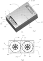
- FIG. 1 designates the parallelepiped container body in which the toroidal rings 2, arranged on the juxtaposed tubular supports 102, in which the primary 202 and secondary 302 windings are arranged, as will be better shown below.
- Container 1 comprises the two half-shells 101 and 201; the upper half-shell 101, provided with the ellipsoidal openings 131 that allow the connection of the ends of the windings, which are housed in the respective semi-ellipsoidal cavities 121, 221 of each half-shell.
- Near the four corners of the outer face of half-shell 101 are formed through holes 111b, perpendicular to the plane of said face; a similar hole 111a is formed centrally to the same face.
- Figure 2 shows the transformer of Figure 1 in cross section; equal parts correspond to equal numerals.
- the structure of the transformer is well shown in the figure, with the toroidal rings 2 supported by the tubular elements 2, shaped to accommodate both the primary 202 and the secondary 302.
- the two juxtaposed sets of rings 2 are located in the semi-cylindrical cavities 141 of the semi-shell 101 and 241 of the semi-shell 201, which are separated from each other by the respective intermediate walls, 151 and 251. Through said walls, through holes 111a and 211a are formed for the insertion of fasteners.
- Figures 3A and 3B show the lower half-shell 201 in perspective; equal parts correspond to equal numerals.
- the through-holes 211a and 211b are arranged in a quincunx pattern; the outer face of Figure 3B is the one that is to contact the means of heat dissipation, such as a cold plate, a radiator, or the like.
- Figures 4A and 4B show the upper half-shell 101 in perspective; equal parts correspond to equal numerals. Highlighted in the figure is the fact that semi-ellipsoidal cavity 121 is completely open at its top, or bottom, and the perimeter of opening 131 corresponds to the maximum perimeter of said cavity 121.
- the outer side walls 161 and the middle wall 151 have the same features as the similar walls described for the lower half-shell 201, as do the through holes 111a and 111b.
- the two half-shells are made of metallic material, and preferably of a highly conductive and preferably lightweight metallic material.
- the use of Al or its alloys is preferred for this purpose.
- the two half-shells of the container can be made by machining with material removal, as well as by die casting.
- the openings 131 formed on the upper half-shell 101 allow the passage of the winding ends, and at the same time keep the said ends at the appropriate distance from the cooling surface on which the transformer is fixed.
- the choice of forming a partition between the two cylindrical cavities descends from two considerations; the first is of a structural order, since an intermediate stiffening line is thus provided in addition to the two side walls 161, 261.
- the second is related to the possibility of inserting in this way at least one means of attachment in the center of the housing, thus making more effective contact with the cooling surface and thus achieving better thermal dissipation.
- the compact design of this container body and the robust fastening system allow for effective vibration control.
- the size of the container body is clearly related to the number and size of the toroidal elements that are provided in the specific high-frequency transformer design.
- the size of the intermediate wall is clearly related to the symmetries of the whole structure, but it is also determined by the minimum size of the fastening means that is chosen to connect the transformer to the cooling surface. In the most generally found cases, the minimum wall thickness can be between 3.0 mm and 7.0 mm, and in the present case a thickness of 4.5 mm is considered.
- the outer side walls have a thickness essentially similar to that of the intermediate wall.
- the regular shape of the container body and the large openings on the top half-shell 101 facilitate an effective vacuum resination process of the assembly. This improves the quality of the resination itself by preventing the formation of air bubbles.
- the new solution in addition to fitting naturally into the construction of a transformer of the type described above, provides at the end of the process a completely electrically insulated element that can be effectively attached to any radiator without the need for any additional insulation or the like.
- the through holes for inserting the fastening means are preferably arranged in a quincunx pattern, as shown in the figures of the accompanying drawings, in order to distribute the fastening load over the entire contact surface of the container body.
- the transformer according to the present invention thus solves the problems highlighted in the state of the art by means of a solution that is simple to implement and effective in heat dissipation.
Landscapes
- Engineering & Computer Science (AREA)
- Power Engineering (AREA)
- Coils Or Transformers For Communication (AREA)
Claims (7)
- Hochfrequenztransformator, umfassend:- ein Paar nebeneinanderliegender röhrenförmiger Lagerelemente (102), wobei auf jedem der röhrenförmigen Elemente (102) eine Vielzahl ringförmiger ferromagnetischer Elemente (2) angeordnet ist, die so bemessen sind, dass sie mit den röhrenförmigen Elementen (102) zusammenwirken und den Kern des Transformators bilden, wobei die Wicklungen (202, 302) des Transformators koaxial zu den röhrenförmigen Elementen (102) angeordnet sind;- einen parallelepipedischen Behälter (1) aus metallischem Material, der aus zwei Halbschalen (101, 201) besteht, wobei jede Halbschale mit einem Paar nebeneinanderliegender halbzylindrischer Hohlräume (141, 241) versehen ist, die zur Aufnahme der ringförmigen ferromagnetischen Elemente (2) geeignet sind,dadurch gekennzeichnet, dass in jeder der beiden Halbschalen (101, 201) auch zwei halbellipsenförmige Hohlräume (121, 221) vorgesehen sind, die sich an den axiale Enden der halbzylindrischen Hohlräume (241) befinden und deren Hauptachse senkrecht zur Längsachse der halbzylindrischen Hohlräume (241) verläuft und die Teile der Wicklungen (202, 302) des Transformators aufnehmen, die sich außerhalb der rohrförmigen Elemente befinden.
- Transformator nach Anspruch 1, bei dem eine Vielzahl von Durchgangslöchern (lila, 111b) durch die beiden Halbschalen (101, 201) senkrecht zu den Längsachsen der vorgenannten halbzylindrischen Hohlräume (141, 241) für die Anbringung von Befestigungsmitteln vorgesehen ist.
- Transformator nach Anspruch 1 oder 2, bei dem eine Halbschale (101) mit Durchgangsöffnungen (131) an der Bodenwand jedes der halbellipsenförmige Hohlräume (121, 221) versehen ist.
- Transformator nach Anspruch 3, bei dem die Durchgangsöffnungen (131) den gleichen Aussenrand haben wie die halbellipsenförmigen Hohlräume (121) .
- Transformator nach einem der Ansprüche 1 bis 4, wobei zwischen den beiden halbzylindrischen Hohlräumen (141, 241) jeder Halbschale (101, 201) eine Zwischenwand (151, 251) mit einer solchen Mindestdicke vorgesehen ist, dass mindestens ein Durchgangsloch (lila) für die Positionierung geeigneter Befestigungsmittel ausgebildet ist.
- Transformator nach Anspruch 5, bei dem eine solche Wand (151, 251) eine Mindestdicke zwischen 3,0 mm und 7,0 mm aufweist.
- Transformator nach einem der vorhergehenden Ansprüche 1 bis 6, wobei der Behälter aus Al oder einer Legierung davon hergestellt ist.
Applications Claiming Priority (2)
| Application Number | Priority Date | Filing Date | Title |
|---|---|---|---|
| IT102021000015065A IT202100015065A1 (it) | 2021-06-09 | 2021-06-09 | Trasformatore ad alta frequenza con dissipazione termica migliorata |
| PCT/IT2022/050149 WO2022259273A1 (en) | 2021-06-09 | 2022-05-30 | High frequency transformer with improved heat dissipation |
Publications (3)
| Publication Number | Publication Date |
|---|---|
| EP4186080A1 EP4186080A1 (de) | 2023-05-31 |
| EP4186080B1 true EP4186080B1 (de) | 2024-10-16 |
| EP4186080C0 EP4186080C0 (de) | 2024-10-16 |
Family
ID=77627314
Family Applications (1)
| Application Number | Title | Priority Date | Filing Date |
|---|---|---|---|
| EP22734377.9A Active EP4186080B1 (de) | 2021-06-09 | 2022-05-30 | Hochfrequenztransformator mit verbesserter wärmeabfuhr |
Country Status (3)
| Country | Link |
|---|---|
| EP (1) | EP4186080B1 (de) |
| IT (1) | IT202100015065A1 (de) |
| WO (1) | WO2022259273A1 (de) |
Families Citing this family (1)
| Publication number | Priority date | Publication date | Assignee | Title |
|---|---|---|---|---|
| IT202300027180A1 (it) | 2023-12-19 | 2025-06-19 | R G M S R L | Trasformatore ad alta frequenza con dissipazione termica migliorata |
Family Cites Families (6)
| Publication number | Priority date | Publication date | Assignee | Title |
|---|---|---|---|---|
| US4134091A (en) * | 1976-12-10 | 1979-01-09 | Rogers Noel A | Low cost, high efficiency radio frequency transformer |
| JP2866793B2 (ja) * | 1993-12-28 | 1999-03-08 | 日立フェライト電子株式会社 | Isdn用パルストランス |
| US6087916A (en) | 1996-07-30 | 2000-07-11 | Soft Switching Technologies, Inc. | Cooling of coaxial winding transformers in high power applications |
| DE19717554A1 (de) * | 1997-04-25 | 1998-10-29 | Abb Daimler Benz Transp | Transformator mit koaxialer Wicklungsanordnung |
| US8704193B1 (en) * | 2012-11-16 | 2014-04-22 | Thermo Fisher Scientific (Bremen) Gmbh | RF transformer |
| IT201700119003A1 (it) | 2017-10-20 | 2019-04-20 | Rgm Spa | Trasformatore ad alta frequenza |
-
2021
- 2021-06-09 IT IT102021000015065A patent/IT202100015065A1/it unknown
-
2022
- 2022-05-30 WO PCT/IT2022/050149 patent/WO2022259273A1/en not_active Ceased
- 2022-05-30 EP EP22734377.9A patent/EP4186080B1/de active Active
Also Published As
| Publication number | Publication date |
|---|---|
| WO2022259273A1 (en) | 2022-12-15 |
| EP4186080C0 (de) | 2024-10-16 |
| EP4186080A1 (de) | 2023-05-31 |
| IT202100015065A1 (it) | 2022-12-09 |
Similar Documents
| Publication | Publication Date | Title |
|---|---|---|
| EP1641003B1 (de) | Kühlung eines Spulenkerns für ein elektrisches Bauelement | |
| EP4186080B1 (de) | Hochfrequenztransformator mit verbesserter wärmeabfuhr | |
| JP5323975B1 (ja) | トランスおよびそのケースの製造方法 | |
| JP6378385B1 (ja) | 端子台を備えたacリアクトル | |
| EP1426984B1 (de) | Transformatoranordnung eines Mikrowellenofens, ihr Herstellungsverfahren und Mikrowellenofen mit einer solchen Transformatoranordnung | |
| JP2013236051A (ja) | 放熱ボビンを有する磁性部材 | |
| JP2013251451A (ja) | インダクタの複合フェライトコアとそれを用いたインダクタ | |
| JP7228159B2 (ja) | トロイダルコイルの搭載構造 | |
| KR200182620Y1 (ko) | 자력 선별기용 전자석 구조 | |
| KR20110115847A (ko) | 열배출수단을 이용한 콤팩트 변압기 | |
| CN117524681B (zh) | 一种用于板式臭氧发生器的谐振式漏感变压器 | |
| EP3579661B1 (de) | Heizspiraleneinheit und induktionserwärmungskocher damit | |
| KR102625348B1 (ko) | 진동 저감부 및 이를 포함하는 변압기 | |
| JPS6156605B2 (de) | ||
| CN212724956U (zh) | 芯主体和电抗器 | |
| JP6049073B2 (ja) | 電子機器 | |
| CN211350334U (zh) | 一种立式结构的阳极饱和电抗器 | |
| CN223450652U (zh) | 用于电力变压器的内置电抗器以及电力变压器 | |
| KR102687954B1 (ko) | 진동 저감부 및 이를 포함하는 변압기 | |
| JP7751985B2 (ja) | コイル装置 | |
| JP2025154646A (ja) | コイル装置 | |
| CN217280315U (zh) | 一种自冷式气体绝缘变压器气箱散热结构 | |
| CN212571859U (zh) | 开关设备 | |
| CN215731228U (zh) | 一种变压器 | |
| KR20250143784A (ko) | 개선된 냉각 기능을 가진 전자기 장치 |
Legal Events
| Date | Code | Title | Description |
|---|---|---|---|
| STAA | Information on the status of an ep patent application or granted ep patent |
Free format text: STATUS: UNKNOWN |
|
| STAA | Information on the status of an ep patent application or granted ep patent |
Free format text: STATUS: THE INTERNATIONAL PUBLICATION HAS BEEN MADE |
|
| PUAI | Public reference made under article 153(3) epc to a published international application that has entered the european phase |
Free format text: ORIGINAL CODE: 0009012 |
|
| STAA | Information on the status of an ep patent application or granted ep patent |
Free format text: STATUS: REQUEST FOR EXAMINATION WAS MADE |
|
| 17P | Request for examination filed |
Effective date: 20230208 |
|
| AK | Designated contracting states |
Kind code of ref document: A1 Designated state(s): AL AT BE BG CH CY CZ DE DK EE ES FI FR GB GR HR HU IE IS IT LI LT LU LV MC MK MT NL NO PL PT RO RS SE SI SK SM TR |
|
| GRAP | Despatch of communication of intention to grant a patent |
Free format text: ORIGINAL CODE: EPIDOSNIGR1 |
|
| STAA | Information on the status of an ep patent application or granted ep patent |
Free format text: STATUS: GRANT OF PATENT IS INTENDED |
|
| GRAS | Grant fee paid |
Free format text: ORIGINAL CODE: EPIDOSNIGR3 |
|
| DAV | Request for validation of the european patent (deleted) | ||
| DAX | Request for extension of the european patent (deleted) | ||
| GRAJ | Information related to disapproval of communication of intention to grant by the applicant or resumption of examination proceedings by the epo deleted |
Free format text: ORIGINAL CODE: EPIDOSDIGR1 |
|
| GRAL | Information related to payment of fee for publishing/printing deleted |
Free format text: ORIGINAL CODE: EPIDOSDIGR3 |
|
| INTG | Intention to grant announced |
Effective date: 20240221 |
|
| STAA | Information on the status of an ep patent application or granted ep patent |
Free format text: STATUS: REQUEST FOR EXAMINATION WAS MADE |
|
| INTC | Intention to grant announced (deleted) | ||
| GRAP | Despatch of communication of intention to grant a patent |
Free format text: ORIGINAL CODE: EPIDOSNIGR1 |
|
| STAA | Information on the status of an ep patent application or granted ep patent |
Free format text: STATUS: GRANT OF PATENT IS INTENDED |
|
| GRAS | Grant fee paid |
Free format text: ORIGINAL CODE: EPIDOSNIGR3 |
|
| INTG | Intention to grant announced |
Effective date: 20240426 |
|
| GRAA | (expected) grant |
Free format text: ORIGINAL CODE: 0009210 |
|
| STAA | Information on the status of an ep patent application or granted ep patent |
Free format text: STATUS: THE PATENT HAS BEEN GRANTED |
|
| AK | Designated contracting states |
Kind code of ref document: B1 Designated state(s): AL AT BE BG CH CY CZ DE DK EE ES FI FR GB GR HR HU IE IS IT LI LT LU LV MC MK MT NL NO PL PT RO RS SE SI SK SM TR |
|
| REG | Reference to a national code |
Ref country code: GB Ref legal event code: FG4D |
|
| REG | Reference to a national code |
Ref country code: CH Ref legal event code: EP |
|
| REG | Reference to a national code |
Ref country code: IE Ref legal event code: FG4D |
|
| REG | Reference to a national code |
Ref country code: DE Ref legal event code: R096 Ref document number: 602022006906 Country of ref document: DE |
|
| U01 | Request for unitary effect filed |
Effective date: 20241112 |
|
| U07 | Unitary effect registered |
Designated state(s): AT BE BG DE DK EE FI FR IT LT LU LV MT NL PT RO SE SI Effective date: 20241122 |
|
| PG25 | Lapsed in a contracting state [announced via postgrant information from national office to epo] |
Ref country code: HR Free format text: LAPSE BECAUSE OF FAILURE TO SUBMIT A TRANSLATION OF THE DESCRIPTION OR TO PAY THE FEE WITHIN THE PRESCRIBED TIME-LIMIT Effective date: 20241016 Ref country code: IS Free format text: LAPSE BECAUSE OF FAILURE TO SUBMIT A TRANSLATION OF THE DESCRIPTION OR TO PAY THE FEE WITHIN THE PRESCRIBED TIME-LIMIT Effective date: 20250216 |
|
| PG25 | Lapsed in a contracting state [announced via postgrant information from national office to epo] |
Ref country code: ES Free format text: LAPSE BECAUSE OF FAILURE TO SUBMIT A TRANSLATION OF THE DESCRIPTION OR TO PAY THE FEE WITHIN THE PRESCRIBED TIME-LIMIT Effective date: 20241016 |
|
| PG25 | Lapsed in a contracting state [announced via postgrant information from national office to epo] |
Ref country code: NO Free format text: LAPSE BECAUSE OF FAILURE TO SUBMIT A TRANSLATION OF THE DESCRIPTION OR TO PAY THE FEE WITHIN THE PRESCRIBED TIME-LIMIT Effective date: 20250116 |
|
| PG25 | Lapsed in a contracting state [announced via postgrant information from national office to epo] |
Ref country code: GR Free format text: LAPSE BECAUSE OF FAILURE TO SUBMIT A TRANSLATION OF THE DESCRIPTION OR TO PAY THE FEE WITHIN THE PRESCRIBED TIME-LIMIT Effective date: 20250117 |
|
| PG25 | Lapsed in a contracting state [announced via postgrant information from national office to epo] |
Ref country code: PL Free format text: LAPSE BECAUSE OF FAILURE TO SUBMIT A TRANSLATION OF THE DESCRIPTION OR TO PAY THE FEE WITHIN THE PRESCRIBED TIME-LIMIT Effective date: 20241016 |
|
| PG25 | Lapsed in a contracting state [announced via postgrant information from national office to epo] |
Ref country code: RS Free format text: LAPSE BECAUSE OF FAILURE TO SUBMIT A TRANSLATION OF THE DESCRIPTION OR TO PAY THE FEE WITHIN THE PRESCRIBED TIME-LIMIT Effective date: 20250116 |
|
| U20 | Renewal fee for the european patent with unitary effect paid |
Year of fee payment: 4 Effective date: 20250527 |
|
| PG25 | Lapsed in a contracting state [announced via postgrant information from national office to epo] |
Ref country code: SM Free format text: LAPSE BECAUSE OF FAILURE TO SUBMIT A TRANSLATION OF THE DESCRIPTION OR TO PAY THE FEE WITHIN THE PRESCRIBED TIME-LIMIT Effective date: 20241016 |
|
| PG25 | Lapsed in a contracting state [announced via postgrant information from national office to epo] |
Ref country code: SK Free format text: LAPSE BECAUSE OF FAILURE TO SUBMIT A TRANSLATION OF THE DESCRIPTION OR TO PAY THE FEE WITHIN THE PRESCRIBED TIME-LIMIT Effective date: 20241016 |
|
| PG25 | Lapsed in a contracting state [announced via postgrant information from national office to epo] |
Ref country code: CZ Free format text: LAPSE BECAUSE OF FAILURE TO SUBMIT A TRANSLATION OF THE DESCRIPTION OR TO PAY THE FEE WITHIN THE PRESCRIBED TIME-LIMIT Effective date: 20241016 |
|
| PLBE | No opposition filed within time limit |
Free format text: ORIGINAL CODE: 0009261 |
|
| STAA | Information on the status of an ep patent application or granted ep patent |
Free format text: STATUS: NO OPPOSITION FILED WITHIN TIME LIMIT |
|
| 26N | No opposition filed |
Effective date: 20250717 |
|
| REG | Reference to a national code |
Ref country code: CH Ref legal event code: H13 Free format text: ST27 STATUS EVENT CODE: U-0-0-H10-H13 (AS PROVIDED BY THE NATIONAL OFFICE) Effective date: 20251223 |
|
| PG25 | Lapsed in a contracting state [announced via postgrant information from national office to epo] |
Ref country code: CH Free format text: LAPSE BECAUSE OF NON-PAYMENT OF DUE FEES Effective date: 20250531 |
|
| PG25 | Lapsed in a contracting state [announced via postgrant information from national office to epo] |
Ref country code: MC Free format text: LAPSE BECAUSE OF FAILURE TO SUBMIT A TRANSLATION OF THE DESCRIPTION OR TO PAY THE FEE WITHIN THE PRESCRIBED TIME-LIMIT Effective date: 20241016 |