EP4183534B1 - Gelenkfunktionseinheit - Google Patents
Gelenkfunktionseinheit Download PDFInfo
- Publication number
- EP4183534B1 EP4183534B1 EP21842209.5A EP21842209A EP4183534B1 EP 4183534 B1 EP4183534 B1 EP 4183534B1 EP 21842209 A EP21842209 A EP 21842209A EP 4183534 B1 EP4183534 B1 EP 4183534B1
- Authority
- EP
- European Patent Office
- Prior art keywords
- function unit
- joint function
- elastic body
- supported
- fixed
- Prior art date
- Legal status (The legal status is an assumption and is not a legal conclusion. Google has not performed a legal analysis and makes no representation as to the accuracy of the status listed.)
- Active
Links
Images




Classifications
-
- A—HUMAN NECESSITIES
- A61—MEDICAL OR VETERINARY SCIENCE; HYGIENE
- A61B—DIAGNOSIS; SURGERY; IDENTIFICATION
- A61B34/00—Computer-aided surgery; Manipulators or robots specially adapted for use in surgery
- A61B34/70—Manipulators specially adapted for use in surgery
- A61B34/71—Manipulators operated by drive cable mechanisms
-
- B—PERFORMING OPERATIONS; TRANSPORTING
- B25—HAND TOOLS; PORTABLE POWER-DRIVEN TOOLS; MANIPULATORS
- B25J—MANIPULATORS; CHAMBERS PROVIDED WITH MANIPULATION DEVICES
- B25J17/00—Joints
- B25J17/02—Wrist joints
-
- A—HUMAN NECESSITIES
- A61—MEDICAL OR VETERINARY SCIENCE; HYGIENE
- A61B—DIAGNOSIS; SURGERY; IDENTIFICATION
- A61B34/00—Computer-aided surgery; Manipulators or robots specially adapted for use in surgery
- A61B34/30—Surgical robots
-
- B—PERFORMING OPERATIONS; TRANSPORTING
- B25—HAND TOOLS; PORTABLE POWER-DRIVEN TOOLS; MANIPULATORS
- B25J—MANIPULATORS; CHAMBERS PROVIDED WITH MANIPULATION DEVICES
- B25J17/00—Joints
-
- B—PERFORMING OPERATIONS; TRANSPORTING
- B25—HAND TOOLS; PORTABLE POWER-DRIVEN TOOLS; MANIPULATORS
- B25J—MANIPULATORS; CHAMBERS PROVIDED WITH MANIPULATION DEVICES
- B25J9/00—Program-controlled manipulators
- B25J9/10—Program-controlled manipulators characterised by positioning means for manipulator elements
- B25J9/104—Program-controlled manipulators characterised by positioning means for manipulator elements with cables, chains or ribbons
-
- A—HUMAN NECESSITIES
- A61—MEDICAL OR VETERINARY SCIENCE; HYGIENE
- A61B—DIAGNOSIS; SURGERY; IDENTIFICATION
- A61B17/00—Surgical instruments, devices or methods
- A61B17/00234—Surgical instruments, devices or methods for minimally invasive surgery
- A61B2017/00292—Surgical instruments, devices or methods for minimally invasive surgery mounted on or guided by flexible, e.g. catheter-like, means
- A61B2017/003—Steerable
- A61B2017/00318—Steering mechanisms
- A61B2017/00323—Cables or rods
-
- A—HUMAN NECESSITIES
- A61—MEDICAL OR VETERINARY SCIENCE; HYGIENE
- A61B—DIAGNOSIS; SURGERY; IDENTIFICATION
- A61B34/00—Computer-aided surgery; Manipulators or robots specially adapted for use in surgery
- A61B34/30—Surgical robots
- A61B2034/305—Details of wrist mechanisms at distal ends of robotic arms
-
- A—HUMAN NECESSITIES
- A61—MEDICAL OR VETERINARY SCIENCE; HYGIENE
- A61B—DIAGNOSIS; SURGERY; IDENTIFICATION
- A61B34/00—Computer-aided surgery; Manipulators or robots specially adapted for use in surgery
- A61B34/70—Manipulators specially adapted for use in surgery
- A61B34/71—Manipulators operated by drive cable mechanisms
- A61B2034/715—Cable tensioning mechanisms for removing slack
Definitions
- the present invention relates to a joint function unit provided for a robot, a manipulator, or the like.
- a problem to be solved is that unintended displacement of a movable-side member occurs due to an external force.
- the purpose of suppressing unintended displacement of a movable-side member is achieved by applying tension, by an elastic body, to a cord-like member for displacing the movable-side member.
- a joint function unit (1) in which a movable-side member (13) is supported so as to be displaceable between a bending position and an extension position with respect to a fixed-side member (11), and the joint function unit (1) includes a plurality of cord-like members (19) and an elastic body (21).
- the cord-like member (19) has a fixed part (27) fixed to the movable-side member (13) on one side in an axial direction and a supported part (29) supported by the fixed-side member (11) on the other side in the axial direction.
- the elastic body (21) may be configured to be arranged in parallel with the plurality of cord-like members (19).
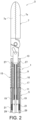
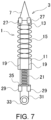
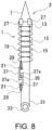
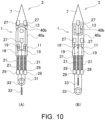
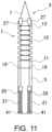
- the joint function unit 1 includes a base part 11, the movable part 13, a flexible member 15, a drive wire 19, and an elastic body 21.
- the flexible member 15 may, by bending and restoring itself, displace the movable part 13 and the end effector 7 with respect to the base part 11 and the shaft 5. Such displacement is performed by the drive wire 19.
- the drive wire 19 is a cord-like member made of metal or the like, and is provided in four places in the joint function unit 1 in a circumferential direction at intervals of 90 degrees in the present embodiment.
- the drive wires 19 facing each other in a radial direction of the joint function unit 1 form a pair.
- two pairs of drive wires 19 are provided.
- These drive wires 19 bend the joint function unit 1 by being pulled in the axial direction, and may be directly or indirectly connected to an operation mechanism (not shown) to be operated in the axial direction. Operation in the axial direction means causing the drive wire 19 to advance or retreat in the axial direction.
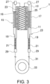
- the elastic body 21 supports the supported part 29 of the drive wire 19 on the base part 11 and energizes the supported part 29 toward a side opposite to the fixed part 27 of the same drive wire 19 in the axial direction. Accordingly, the elastic body 21 applies tension to each drive wire 19 and improves bending rigidity of each drive wire 19.
- the elastic body 21 of the present embodiment is composed of a coil spring, particularly a compression spring having a pitch.
- the elastic body 21 may be made of metal, resin, or the like, and may have an appropriate shape depending on an elastic modulus or the like.
- the elastic body may have a columnar shape or tubular shape.
- the elastic body 21 is configured to be arranged in parallel with the drive wire 19 so as to exert elastic force in the axial direction.
- parallel refers to arranging the elastic body 21 so that the axial direction and a direction in which the elastic force acts are parallel. However, the two directions do not have to be strictly parallel, and the term “parallel” may also include a case where one of the two directions is slightly inclined with respect to the other.
- the elastic body 21 between the supported part 29 and the base part 11 may be omitted, and the guide part 33 may be configured to be pulled by the elastic body 21.
- Each elastic body 21 has an axial dimension in a free state set smaller than an axial dimension between the supported part 29 and the base part 11. Hence, each elastic body 21 is compressed between the supported part 29 and the base part 11 according to a dimensional difference. Due to this compression, a load is applied to each elastic body 21 and tension corresponding to the load is applied to the drive wire 19.
- the elastic body 21 like this, together with the flexible member 15, is able to impart to the joint function unit 1 the linear load characteristic that a load increases as a bending angle increases.
- the load characteristic will be described later.
- FIG. 4 are conceptual views of the manipulator of FIG. 1 , in which (A) of FIG. 4 shows a normal state and (B) of FIG. 4 shows a bending state.
- the joint function unit 1 is bent by pulling any one of the drive wires 19.
- the joint function unit 1 360 degrees in all directions. Accordingly, the end effector 7 can be oriented in a desired direction.
- the supported part 29 of the drive wire 19 (referred to as inner wire 19) is displaced so as to widen a space between itself and the base part 11 in the axial direction. Accordingly, the fixed part 27 of the inner wire 19 is pulled toward the base part 11 side.
- the inner wire 19 is subjected to tension greater than that in the normal state. As a result, the inner wire 19 is improved in bending rigidity.
- the elastic body 21 coaxial with the outer wire 19 is compressed against its own elastic force, and the elastic body 21 coaxial with the inner wire 19 attempts to extend between the supported part 29 and the base part 11 by its own elastic force.
- the outer wire 19 is given tension without loosening.
- the outer wire 19 is also improved in bending rigidity, together with the inner wire 19.
- FIG. 5 is a graph showing a relationship between displacement amount with respect to external force and load of an elastic body.
Landscapes
- Engineering & Computer Science (AREA)
- Health & Medical Sciences (AREA)
- Robotics (AREA)
- Surgery (AREA)
- Life Sciences & Earth Sciences (AREA)
- Mechanical Engineering (AREA)
- Medical Informatics (AREA)
- Heart & Thoracic Surgery (AREA)
- Biomedical Technology (AREA)
- Molecular Biology (AREA)
- Animal Behavior & Ethology (AREA)
- General Health & Medical Sciences (AREA)
- Public Health (AREA)
- Veterinary Medicine (AREA)
- Nuclear Medicine, Radiotherapy & Molecular Imaging (AREA)
- Manipulator (AREA)
- Surgical Instruments (AREA)
Claims (8)
- Verbindungfunktionseinheit (1), bei der ein Element mit beweglicher Seite (7, 13) so gelagert ist, dass es zwischen einer Biegeposition und einer Streckungsposition in Bezug auf ein Element mit befestigter Seite (11) verschiebbar ist, wobei die Verbindungfunktionseinheit (1) umfasst:
eine Vielzahl von Antriebsdrähten (19), die jeweils ein befestigtes Teil (27), das an das Element mit beweglicher Seite (7, 13) auf einer Seite in einer axialen Richtung befestigt ist, und ein gelagertes Teil (29) aufweist, das von dem Element mit befestigter Seite (11) auf der anderen Seite in der axialen Richtung gelagert wird; und
einen elastischen Körper (21), der so konfiguriert ist, dass er die gelagerten Teile (29) der Vielzahl von Antriebsdrähten (19) an dem Element mit befestigter Seite (11) lagert, die gelagerten Teile (29) in Richtung einer Seite, gegenüber zu den befestigten Teilen (27) in der axialen Richtung energetisiert und auf die Vielzahl von Antriebsdrähten (19) Spannung aufbringt, wobei
jeder der Vielzahl von Antriebsdrähten (19) durch das Element mit befestigter Seite (11) zwischen dem befestigten Teil (27) und dem gelagerten Teil (29) eingeführt ist, und
der elastische Körper (21) zwischen den gelagerten Teilen (29) der Vielzahl von Antriebsdrähten (19) und dem Element mit befestigter Seite (11) zwischenpositioniert ist. - Verbindungfunktionseinheit (1) gemäß Anspruch 1, wobei
der elastische Körper (21) parallel zu der Vielzahl von Antriebsdrähten (19) angeordnet ist. - Verbindungfunktionseinheit (1) gemäß Anspruch 1, wobei
der elastische Körper (21) jeden der Vielzahl von Antriebsdrähten (19) dort hindurch eingeführt und auf einer gleichen Achse bereitgestellt aufweist. - Verbindungfunktionseinheit (1) gemäß Anspruch 1, ferner umfassend:
ein Lagerelement (35), das sich zwischen den gelagerten Teilen (29) der Vielzahl von Antriebsdrähten (19) erstreckt, wobei
der elastische Körper (21) zwischen dem Lagerelement (35) und dem Element mit befestigter Seite (11) zwischenpositioniert ist. - Verbindungfunktionseinheit (1) gemäß Anspruch 1 oder 2, ferner umfassend:
ein Führungsteil (33), das so konfiguriert ist, dass es einen der Vielzahl von Antriebsdrähten (19) führt und die gelagerten Teile (29) der Vielzahl von Antriebsdrähten (19) auf einer gleichen Achse anordnet, wobei
der elastische Körper (21) so konfiguriert ist, dass er die gelagerten Teile (29) der Vielzahl von Antriebsdrähte (19) zwischenverbindet. - Verbindungfunktionseinheit (1) gemäß Anspruch 1 oder 2, wobei
das Element mit befestigter Seite (11) ein Lagerteil (41) umfasst, das sich an einer Seite, gegenüber dem befestigten Teil (27), befindet, wobei sich die gelagerten Teile (29) der Vielzahl von Antriebsdrähten (19) in der axialen Richtung dazwischen befinden; und
der elastische Körper (21) zwischen dem Lagerteil (41) und den gelagerten Teilen (29) der Vielzahl von Antriebsdrähten (19) zwischenpositioniert ist. - Verbindungfunktionseinheit (1) gemäß einem der Ansprüche 1 bis 6, wobei
der elastische Körper (21) eine Schraubenfeder ist. - Verbindungfunktionseinheit (1) gemäß einem der Ansprüche 1 bis 7, wobei
die gelagerten Teile (29) in der axialen Richtung betätigt werden, um das Element mit beweglicher Seite (7, 13) in Bezug auf das Element mit befestigter Seite (11) zu verschieben.
Applications Claiming Priority (2)
| Application Number | Priority Date | Filing Date | Title |
|---|---|---|---|
| JP2020122343A JP7498611B2 (ja) | 2020-07-16 | 2020-07-16 | 関節機能部 |
| PCT/JP2021/026388 WO2022014628A1 (ja) | 2020-07-16 | 2021-07-14 | 関節機能部 |
Publications (3)
| Publication Number | Publication Date |
|---|---|
| EP4183534A1 EP4183534A1 (de) | 2023-05-24 |
| EP4183534A4 EP4183534A4 (de) | 2023-12-20 |
| EP4183534B1 true EP4183534B1 (de) | 2025-06-25 |
Family
ID=79554689
Family Applications (1)
| Application Number | Title | Priority Date | Filing Date |
|---|---|---|---|
| EP21842209.5A Active EP4183534B1 (de) | 2020-07-16 | 2021-07-14 | Gelenkfunktionseinheit |
Country Status (6)
| Country | Link |
|---|---|
| US (1) | US12337468B2 (de) |
| EP (1) | EP4183534B1 (de) |
| JP (1) | JP7498611B2 (de) |
| CN (1) | CN115776931B (de) |
| TW (1) | TW202216082A (de) |
| WO (1) | WO2022014628A1 (de) |
Families Citing this family (2)
| Publication number | Priority date | Publication date | Assignee | Title |
|---|---|---|---|---|
| WO2024089878A1 (ja) * | 2022-10-28 | 2024-05-02 | 日本発條株式会社 | 屈曲構造体 |
| JP2024078850A (ja) * | 2022-11-30 | 2024-06-11 | 日本発條株式会社 | ガイドワイヤ |
Family Cites Families (19)
| Publication number | Priority date | Publication date | Assignee | Title |
|---|---|---|---|---|
| JP2987452B2 (ja) * | 1990-05-17 | 1999-12-06 | オリンパス光学工業株式会社 | 内視鏡 |
| JP3765218B2 (ja) * | 2000-02-03 | 2006-04-12 | フジノン株式会社 | 内視鏡の操作ワイヤガイド装置 |
| US20060178556A1 (en) * | 2001-06-29 | 2006-08-10 | Intuitive Surgical, Inc. | Articulate and swapable endoscope for a surgical robot |
| US8105350B2 (en) | 2006-05-23 | 2012-01-31 | Cambridge Endoscopic Devices, Inc. | Surgical instrument |
| JP5364255B2 (ja) * | 2007-10-31 | 2013-12-11 | テルモ株式会社 | 医療用マニピュレータ |
| US9259274B2 (en) | 2008-09-30 | 2016-02-16 | Intuitive Surgical Operations, Inc. | Passive preload and capstan drive for surgical instruments |
| JP2011072570A (ja) | 2009-09-30 | 2011-04-14 | Terumo Corp | 医療用マニピュレータ |
| US9101379B2 (en) | 2010-11-12 | 2015-08-11 | Intuitive Surgical Operations, Inc. | Tension control in actuation of multi-joint medical instruments |
| KR101798060B1 (ko) | 2011-06-03 | 2017-11-15 | 삼성전자주식회사 | 수술 장치 |
| EP3791822A1 (de) * | 2012-11-02 | 2021-03-17 | Intuitive Surgical Operations, Inc. | Selbstantagonistischer antrieb für medizinische instrumente |
| JP6150672B2 (ja) | 2013-08-26 | 2017-06-21 | オリンパス株式会社 | 医療用マニピュレータ |
| JP5917467B2 (ja) * | 2013-09-26 | 2016-05-18 | 富士フイルム株式会社 | 内視鏡 |
| JP6049585B2 (ja) | 2013-10-31 | 2016-12-21 | オリンパス株式会社 | 術具 |
| JP6353665B2 (ja) * | 2014-02-21 | 2018-07-04 | オリンパス株式会社 | マニピュレータの初期化方法、マニピュレータ、およびマニピュレータシステム |
| WO2016129336A1 (ja) | 2015-02-13 | 2016-08-18 | オリンパス株式会社 | マニピュレータ |
| WO2016136301A1 (ja) | 2015-02-25 | 2016-09-01 | オリンパス株式会社 | マニピュレータ及びマニピュレータシステム |
| US9545727B1 (en) * | 2015-11-05 | 2017-01-17 | Irobot Corporation | Robotic fingers and end effectors including same |
| US10086192B2 (en) | 2016-07-07 | 2018-10-02 | Modular Bionics Inc. | Neural interface insertion and retraction tools |
| DE112017003832B4 (de) | 2016-07-30 | 2023-05-17 | Life Robotics Inc. | Roboterarmmechanismus |
-
2020
- 2020-07-16 JP JP2020122343A patent/JP7498611B2/ja active Active
-
2021
- 2021-06-28 TW TW110123585A patent/TW202216082A/zh unknown
- 2021-07-14 CN CN202180048499.1A patent/CN115776931B/zh active Active
- 2021-07-14 US US18/015,537 patent/US12337468B2/en active Active
- 2021-07-14 EP EP21842209.5A patent/EP4183534B1/de active Active
- 2021-07-14 WO PCT/JP2021/026388 patent/WO2022014628A1/ja not_active Ceased
Also Published As
| Publication number | Publication date |
|---|---|
| US20230256625A1 (en) | 2023-08-17 |
| CN115776931A (zh) | 2023-03-10 |
| WO2022014628A1 (ja) | 2022-01-20 |
| EP4183534A1 (de) | 2023-05-24 |
| EP4183534A4 (de) | 2023-12-20 |
| US12337468B2 (en) | 2025-06-24 |
| JP2022018904A (ja) | 2022-01-27 |
| TW202216082A (zh) | 2022-05-01 |
| JP7498611B2 (ja) | 2024-06-12 |
| CN115776931B (zh) | 2025-09-16 |
Similar Documents
| Publication | Publication Date | Title |
|---|---|---|
| US12023114B2 (en) | Passive preload and capstan drive for surgical instruments | |
| KR102291821B1 (ko) | 수술 기구용 손목 장치 | |
| EP3838518A1 (de) | Biegestruktur und gelenkfunktionsbauteil | |
| EP4183534B1 (de) | Gelenkfunktionseinheit | |
| US20130089392A1 (en) | Driving force transmission mechanism and manipulator system | |
| EP4238723B1 (de) | Biegestrukturkörper | |
| WO2023095861A1 (ja) | 屈曲構造体及びその半製品 | |
| KR101790442B1 (ko) | 수술용 기기 | |
| WO2025172566A1 (en) | Surgical instrument having a shaft assembly with a kinematic chain | |
| JP2025167880A (ja) | ケーブルの進退機構及びこれを用いたエンドエフェクターアッセンブリー | |
| CN120267409A (zh) | 医用柔性机械臂和手术机器人 |
Legal Events
| Date | Code | Title | Description |
|---|---|---|---|
| STAA | Information on the status of an ep patent application or granted ep patent |
Free format text: STATUS: THE INTERNATIONAL PUBLICATION HAS BEEN MADE |
|
| PUAI | Public reference made under article 153(3) epc to a published international application that has entered the european phase |
Free format text: ORIGINAL CODE: 0009012 |
|
| STAA | Information on the status of an ep patent application or granted ep patent |
Free format text: STATUS: REQUEST FOR EXAMINATION WAS MADE |
|
| 17P | Request for examination filed |
Effective date: 20221229 |
|
| AK | Designated contracting states |
Kind code of ref document: A1 Designated state(s): AL AT BE BG CH CY CZ DE DK EE ES FI FR GB GR HR HU IE IS IT LI LT LU LV MC MK MT NL NO PL PT RO RS SE SI SK SM TR |
|
| DAV | Request for validation of the european patent (deleted) | ||
| DAX | Request for extension of the european patent (deleted) | ||
| A4 | Supplementary search report drawn up and despatched |
Effective date: 20231121 |
|
| RIC1 | Information provided on ipc code assigned before grant |
Ipc: A61B 17/29 20060101ALI20231115BHEP Ipc: B25J 17/02 20060101AFI20231115BHEP |
|
| GRAP | Despatch of communication of intention to grant a patent |
Free format text: ORIGINAL CODE: EPIDOSNIGR1 |
|
| STAA | Information on the status of an ep patent application or granted ep patent |
Free format text: STATUS: GRANT OF PATENT IS INTENDED |
|
| INTG | Intention to grant announced |
Effective date: 20250220 |
|
| GRAS | Grant fee paid |
Free format text: ORIGINAL CODE: EPIDOSNIGR3 |
|
| GRAA | (expected) grant |
Free format text: ORIGINAL CODE: 0009210 |
|
| STAA | Information on the status of an ep patent application or granted ep patent |
Free format text: STATUS: THE PATENT HAS BEEN GRANTED |
|
| P01 | Opt-out of the competence of the unified patent court (upc) registered |
Free format text: CASE NUMBER: APP_20123/2025 Effective date: 20250428 |
|
| AK | Designated contracting states |
Kind code of ref document: B1 Designated state(s): AL AT BE BG CH CY CZ DE DK EE ES FI FR GB GR HR HU IE IS IT LI LT LU LV MC MK MT NL NO PL PT RO RS SE SI SK SM TR |
|
| REG | Reference to a national code |
Ref country code: GB Ref legal event code: FG4D |
|
| REG | Reference to a national code |
Ref country code: CH Ref legal event code: EP |
|
| PGFP | Annual fee paid to national office [announced via postgrant information from national office to epo] |
Ref country code: GB Payment date: 20250630 Year of fee payment: 5 |
|
| REG | Reference to a national code |
Ref country code: CH Ref legal event code: EP |
|
| REG | Reference to a national code |
Ref country code: IE Ref legal event code: FG4D |
|
| REG | Reference to a national code |
Ref country code: DE Ref legal event code: R096 Ref document number: 602021033035 Country of ref document: DE |
|
| REG | Reference to a national code |
Ref country code: NL Ref legal event code: FP |
|
| PGFP | Annual fee paid to national office [announced via postgrant information from national office to epo] |
Ref country code: NL Payment date: 20250710 Year of fee payment: 5 |
|
| PG25 | Lapsed in a contracting state [announced via postgrant information from national office to epo] |
Ref country code: FI Free format text: LAPSE BECAUSE OF FAILURE TO SUBMIT A TRANSLATION OF THE DESCRIPTION OR TO PAY THE FEE WITHIN THE PRESCRIBED TIME-LIMIT Effective date: 20250625 |
|
| PGFP | Annual fee paid to national office [announced via postgrant information from national office to epo] |
Ref country code: DE Payment date: 20250626 Year of fee payment: 5 |
|
| REG | Reference to a national code |
Ref country code: LT Ref legal event code: MG9D |
|
| PG25 | Lapsed in a contracting state [announced via postgrant information from national office to epo] |
Ref country code: NO Free format text: LAPSE BECAUSE OF FAILURE TO SUBMIT A TRANSLATION OF THE DESCRIPTION OR TO PAY THE FEE WITHIN THE PRESCRIBED TIME-LIMIT Effective date: 20250925 Ref country code: GR Free format text: LAPSE BECAUSE OF FAILURE TO SUBMIT A TRANSLATION OF THE DESCRIPTION OR TO PAY THE FEE WITHIN THE PRESCRIBED TIME-LIMIT Effective date: 20250926 |
|
| PG25 | Lapsed in a contracting state [announced via postgrant information from national office to epo] |
Ref country code: BG Free format text: LAPSE BECAUSE OF FAILURE TO SUBMIT A TRANSLATION OF THE DESCRIPTION OR TO PAY THE FEE WITHIN THE PRESCRIBED TIME-LIMIT Effective date: 20250625 |
|
| PG25 | Lapsed in a contracting state [announced via postgrant information from national office to epo] |
Ref country code: HR Free format text: LAPSE BECAUSE OF FAILURE TO SUBMIT A TRANSLATION OF THE DESCRIPTION OR TO PAY THE FEE WITHIN THE PRESCRIBED TIME-LIMIT Effective date: 20250625 |
|
| PGFP | Annual fee paid to national office [announced via postgrant information from national office to epo] |
Ref country code: FR Payment date: 20250715 Year of fee payment: 5 Ref country code: AT Payment date: 20251020 Year of fee payment: 5 |
|
| PG25 | Lapsed in a contracting state [announced via postgrant information from national office to epo] |
Ref country code: RS Free format text: LAPSE BECAUSE OF FAILURE TO SUBMIT A TRANSLATION OF THE DESCRIPTION OR TO PAY THE FEE WITHIN THE PRESCRIBED TIME-LIMIT Effective date: 20250925 |
|
| PGFP | Annual fee paid to national office [announced via postgrant information from national office to epo] |
Ref country code: IE Payment date: 20250731 Year of fee payment: 5 |
|
| PG25 | Lapsed in a contracting state [announced via postgrant information from national office to epo] |
Ref country code: LV Free format text: LAPSE BECAUSE OF FAILURE TO SUBMIT A TRANSLATION OF THE DESCRIPTION OR TO PAY THE FEE WITHIN THE PRESCRIBED TIME-LIMIT Effective date: 20250625 |
|
| PG25 | Lapsed in a contracting state [announced via postgrant information from national office to epo] |
Ref country code: PT Free format text: LAPSE BECAUSE OF FAILURE TO SUBMIT A TRANSLATION OF THE DESCRIPTION OR TO PAY THE FEE WITHIN THE PRESCRIBED TIME-LIMIT Effective date: 20251027 |
|
| REG | Reference to a national code |
Ref country code: AT Ref legal event code: MK05 Ref document number: 1806008 Country of ref document: AT Kind code of ref document: T Effective date: 20250625 |
|
| PG25 | Lapsed in a contracting state [announced via postgrant information from national office to epo] |
Ref country code: IS Free format text: LAPSE BECAUSE OF FAILURE TO SUBMIT A TRANSLATION OF THE DESCRIPTION OR TO PAY THE FEE WITHIN THE PRESCRIBED TIME-LIMIT Effective date: 20251025 |
|
| PG25 | Lapsed in a contracting state [announced via postgrant information from national office to epo] |
Ref country code: AT Free format text: LAPSE BECAUSE OF FAILURE TO SUBMIT A TRANSLATION OF THE DESCRIPTION OR TO PAY THE FEE WITHIN THE PRESCRIBED TIME-LIMIT Effective date: 20250625 Ref country code: SM Free format text: LAPSE BECAUSE OF FAILURE TO SUBMIT A TRANSLATION OF THE DESCRIPTION OR TO PAY THE FEE WITHIN THE PRESCRIBED TIME-LIMIT Effective date: 20250625 |
|
| PG25 | Lapsed in a contracting state [announced via postgrant information from national office to epo] |
Ref country code: CZ Free format text: LAPSE BECAUSE OF FAILURE TO SUBMIT A TRANSLATION OF THE DESCRIPTION OR TO PAY THE FEE WITHIN THE PRESCRIBED TIME-LIMIT Effective date: 20250625 |
|
| PG25 | Lapsed in a contracting state [announced via postgrant information from national office to epo] |
Ref country code: PL Free format text: LAPSE BECAUSE OF FAILURE TO SUBMIT A TRANSLATION OF THE DESCRIPTION OR TO PAY THE FEE WITHIN THE PRESCRIBED TIME-LIMIT Effective date: 20250625 |
|
| PG25 | Lapsed in a contracting state [announced via postgrant information from national office to epo] |
Ref country code: EE Free format text: LAPSE BECAUSE OF FAILURE TO SUBMIT A TRANSLATION OF THE DESCRIPTION OR TO PAY THE FEE WITHIN THE PRESCRIBED TIME-LIMIT Effective date: 20250625 |
|
| PG25 | Lapsed in a contracting state [announced via postgrant information from national office to epo] |
Ref country code: SK Free format text: LAPSE BECAUSE OF FAILURE TO SUBMIT A TRANSLATION OF THE DESCRIPTION OR TO PAY THE FEE WITHIN THE PRESCRIBED TIME-LIMIT Effective date: 20250625 |
|
| PG25 | Lapsed in a contracting state [announced via postgrant information from national office to epo] |
Ref country code: ES Free format text: LAPSE BECAUSE OF FAILURE TO SUBMIT A TRANSLATION OF THE DESCRIPTION OR TO PAY THE FEE WITHIN THE PRESCRIBED TIME-LIMIT Effective date: 20250625 |
|
| REG | Reference to a national code |
Ref country code: CH Ref legal event code: H13 Free format text: ST27 STATUS EVENT CODE: U-0-0-H10-H13 (AS PROVIDED BY THE NATIONAL OFFICE) Effective date: 20260224 |
|
| PG25 | Lapsed in a contracting state [announced via postgrant information from national office to epo] |
Ref country code: LU Free format text: LAPSE BECAUSE OF NON-PAYMENT OF DUE FEES Effective date: 20250714 Ref country code: RO Free format text: LAPSE BECAUSE OF FAILURE TO SUBMIT A TRANSLATION OF THE DESCRIPTION OR TO PAY THE FEE WITHIN THE PRESCRIBED TIME-LIMIT Effective date: 20250625 |
|
| REG | Reference to a national code |
Ref country code: BE Ref legal event code: MM Effective date: 20250731 |
|
| PG25 | Lapsed in a contracting state [announced via postgrant information from national office to epo] |
Ref country code: MC Free format text: LAPSE BECAUSE OF FAILURE TO SUBMIT A TRANSLATION OF THE DESCRIPTION OR TO PAY THE FEE WITHIN THE PRESCRIBED TIME-LIMIT Effective date: 20250625 |
|
| PG25 | Lapsed in a contracting state [announced via postgrant information from national office to epo] |
Ref country code: DK Free format text: LAPSE BECAUSE OF FAILURE TO SUBMIT A TRANSLATION OF THE DESCRIPTION OR TO PAY THE FEE WITHIN THE PRESCRIBED TIME-LIMIT Effective date: 20250625 |
|
| PG25 | Lapsed in a contracting state [announced via postgrant information from national office to epo] |
Ref country code: BE Free format text: LAPSE BECAUSE OF NON-PAYMENT OF DUE FEES Effective date: 20250731 Ref country code: IT Free format text: LAPSE BECAUSE OF FAILURE TO SUBMIT A TRANSLATION OF THE DESCRIPTION OR TO PAY THE FEE WITHIN THE PRESCRIBED TIME-LIMIT Effective date: 20250625 |
|
| PG25 | Lapsed in a contracting state [announced via postgrant information from national office to epo] |
Ref country code: CH Free format text: LAPSE BECAUSE OF NON-PAYMENT OF DUE FEES Effective date: 20250731 |
|
| PLBE | No opposition filed within time limit |
Free format text: ORIGINAL CODE: 0009261 |
|
| STAA | Information on the status of an ep patent application or granted ep patent |
Free format text: STATUS: NO OPPOSITION FILED WITHIN TIME LIMIT |