EP4182196B1 - Verfahren und vorrichtung zum ermitteln einer spannkraft einer bremseinrichtung eines kraftfahrzeugs - Google Patents
Verfahren und vorrichtung zum ermitteln einer spannkraft einer bremseinrichtung eines kraftfahrzeugs Download PDFInfo
- Publication number
- EP4182196B1 EP4182196B1 EP21737583.1A EP21737583A EP4182196B1 EP 4182196 B1 EP4182196 B1 EP 4182196B1 EP 21737583 A EP21737583 A EP 21737583A EP 4182196 B1 EP4182196 B1 EP 4182196B1
- Authority
- EP
- European Patent Office
- Prior art keywords
- clamping force
- determined
- brake
- rotor
- motor
- Prior art date
- Legal status (The legal status is an assumption and is not a legal conclusion. Google has not performed a legal analysis and makes no representation as to the accuracy of the status listed.)
- Active
Links
Images


Classifications
-
- B—PERFORMING OPERATIONS; TRANSPORTING
- B60—VEHICLES IN GENERAL
- B60T—VEHICLE BRAKE CONTROL SYSTEMS OR PARTS THEREOF; BRAKE CONTROL SYSTEMS OR PARTS THEREOF, IN GENERAL; ARRANGEMENT OF BRAKING ELEMENTS ON VEHICLES IN GENERAL; PORTABLE DEVICES FOR PREVENTING UNWANTED MOVEMENT OF VEHICLES; VEHICLE MODIFICATIONS TO FACILITATE COOLING OF BRAKES
- B60T13/00—Transmitting braking action from initiating means to ultimate brake actuator with power assistance or drive; Brake systems incorporating such transmitting means, e.g. air-pressure brake systems
- B60T13/74—Transmitting braking action from initiating means to ultimate brake actuator with power assistance or drive; Brake systems incorporating such transmitting means, e.g. air-pressure brake systems with electrical assistance or drive
- B60T13/741—Transmitting braking action from initiating means to ultimate brake actuator with power assistance or drive; Brake systems incorporating such transmitting means, e.g. air-pressure brake systems with electrical assistance or drive acting on an ultimate actuator
-
- B—PERFORMING OPERATIONS; TRANSPORTING
- B60—VEHICLES IN GENERAL
- B60T—VEHICLE BRAKE CONTROL SYSTEMS OR PARTS THEREOF; BRAKE CONTROL SYSTEMS OR PARTS THEREOF, IN GENERAL; ARRANGEMENT OF BRAKING ELEMENTS ON VEHICLES IN GENERAL; PORTABLE DEVICES FOR PREVENTING UNWANTED MOVEMENT OF VEHICLES; VEHICLE MODIFICATIONS TO FACILITATE COOLING OF BRAKES
- B60T13/00—Transmitting braking action from initiating means to ultimate brake actuator with power assistance or drive; Brake systems incorporating such transmitting means, e.g. air-pressure brake systems
- B60T13/74—Transmitting braking action from initiating means to ultimate brake actuator with power assistance or drive; Brake systems incorporating such transmitting means, e.g. air-pressure brake systems with electrical assistance or drive
- B60T13/746—Transmitting braking action from initiating means to ultimate brake actuator with power assistance or drive; Brake systems incorporating such transmitting means, e.g. air-pressure brake systems with electrical assistance or drive and mechanical transmission of the braking action
-
- B—PERFORMING OPERATIONS; TRANSPORTING
- B60—VEHICLES IN GENERAL
- B60T—VEHICLE BRAKE CONTROL SYSTEMS OR PARTS THEREOF; BRAKE CONTROL SYSTEMS OR PARTS THEREOF, IN GENERAL; ARRANGEMENT OF BRAKING ELEMENTS ON VEHICLES IN GENERAL; PORTABLE DEVICES FOR PREVENTING UNWANTED MOVEMENT OF VEHICLES; VEHICLE MODIFICATIONS TO FACILITATE COOLING OF BRAKES
- B60T17/00—Component parts, details, or accessories of power brake systems not covered by groups B60T8/00, B60T13/00 or B60T15/00, or presenting other characteristic features
- B60T17/18—Safety devices; Monitoring
- B60T17/22—Devices for monitoring or checking brake systems; Signal devices
-
- B—PERFORMING OPERATIONS; TRANSPORTING
- B60—VEHICLES IN GENERAL
- B60T—VEHICLE BRAKE CONTROL SYSTEMS OR PARTS THEREOF; BRAKE CONTROL SYSTEMS OR PARTS THEREOF, IN GENERAL; ARRANGEMENT OF BRAKING ELEMENTS ON VEHICLES IN GENERAL; PORTABLE DEVICES FOR PREVENTING UNWANTED MOVEMENT OF VEHICLES; VEHICLE MODIFICATIONS TO FACILITATE COOLING OF BRAKES
- B60T8/00—Arrangements for adjusting wheel-braking force to meet varying vehicular or ground-surface conditions, e.g. limiting or varying distribution of braking force
- B60T8/17—Using electrical or electronic regulation means to control braking
- B60T8/171—Detecting parameters used in the regulation; Measuring values used in the regulation
Definitions
- the invention relates to a method for determining a clamping force of a braking device of a motor vehicle, wherein the motor vehicle has at least one rotatably mounted wheel and a braking system with at least one braking device and at least one electric motor, wherein the braking device has a braking element connected to the wheel in a rotationally fixed manner and at least one braking body that can be pressed against the braking element, wherein the electric motor has a motor winding and a rotatably mounted rotor, wherein the rotor is coupled to the braking body by a gear device in such a way that a clamping force can be generated by rotating the rotor, by means of which the braking body is pressed against the braking element, wherein the rotor can be rotated by applying an electric motor current to the motor winding, wherein an angle of rotation of the rotor and/or a displacement path of a displaceably mounted element of the gear device are determined, and wherein a level of the clamping force generated is determined as
- the invention relates to a method for operating a motor vehicle.
- the invention relates to a device for determining a clamping force, with an evaluation device.
- a motor vehicle usually has several rotatably mounted wheels.
- the motor vehicle In order to reduce the driving speed of the motor vehicle, the motor vehicle usually has a braking system with at least one braking device.
- the braking device is assigned to one of the wheels of the motor vehicle and is designed to generate a frictional braking torque by means of which a current rotational speed of the wheel is reduced.
- the braking device has a braking element connected to the wheel in a rotationally fixed manner, such as a brake disk, and at least one braking body that can be pressed against the braking element. If the braking body is pressed against the braking element, the frictional braking torque is generated.
- the braking system preferably has several braking devices, each of the braking devices being assigned to a different one of the wheels.
- Brake systems are increasingly also having an electric motor with a multi-phase motor winding and a rotatably mounted rotor to actuate the braking device.
- the rotor is coupled to the brake body by a gear device in such a way that a clamping force can be generated by rotating the rotor, which presses the brake body against the braking element.
- the rotation of the rotor is thus converted by the gear device into a displacement of the brake body.
- the level of the clamping force generated corresponds to the level of the friction braking torque. The higher the clamping force, the higher the friction braking torque.
- the rotor can be rotated by applying an electric motor current to the motor winding.
- Methods for determining the level of the clamping force generated are known from the prior art. Knowing the clamping force enables advantageous control of the electric motor. It is known to determine a rotation angle of the rotor and/or a displacement path of a displaceably mounted element of the gear device. The rotation angle and the displacement path correspond to the level of the clamping force. The larger the rotation angle or the displacement path, the greater the clamping force generated. The level of the clamping force is then determined accordingly depending on the rotation angle and/or the displacement path.
- the patent specification KR 101 338 433 B1 discloses a method for determining a clamping force of a braking device, in which the clamping force is determined as a function of a rotation angle of a rotor of an electric motor and as a function of a motor current level of the electric motor. Such a method is also described in the published documents EP 3 156 294 A1 and US 2017/321773 A1 described.
- the method according to the invention with the features of claim 1 has the advantage that the accuracy with which the level of the tension force generated is determined is increased.
- a level of the motor current is determined and that the level of the tension force is determined as a function of the level of the motor current.
- the sole consideration of the angle of rotation and/or the displacement path leads to inaccuracies in determining the level of the tension force generated as the absolute angle of rotation or displacement path increases. These inaccuracies are at least partially compensated by the additional consideration of the level of the motor current.
- the level of the motor current also corresponds to the level of the tension force generated, at least at certain operating points of the electric motor. For example, the tension force increases with an increase in the motor current.
- the motor current is preferably recorded or measured. This also means determining the motor current. There is then a sensor device that is designed to record the level of the motor current. Alternatively, a parameter is preferably recorded or measured that corresponds to the level of the motor current, for example an electrical motor voltage of the motor winding. The level of the motor current is then determined depending on the recorded parameter.
- the level of the clamping force is determined as a function of a first characteristic curve that describes the clamping force as a function of the angle of rotation or the displacement path.
- the clamping force generated can be precisely determined.
- a corresponding clamping force can be assigned to a large number of angles of rotation or displacement paths.
- the first characteristic curve is changed depending on the determined level of the motor current. This makes it easy to take the level of the motor current into account for evaluation purposes. For example, a slope of the first characteristic curve is changed depending on the determined level of the motor current.
- a corrected angle of rotation is determined as a function of the level of the motor current on the one hand and the determined angle of rotation on the other hand, wherein the level of the clamping force is determined as a function of the corrected angle of rotation, and/or a corrected displacement path is determined as a function of the level of the motor current on the one hand and the determined displacement path on the other hand, wherein the level of the clamping force is determined as a function of the corrected displacement path.
- the originally determined angle of rotation or the originally determined displacement path are therefore corrected as a function of the determined level of the motor current.
- a correction factor is determined as a function of the level of the motor current and the determined angle of rotation or the determined displacement path is multiplied by the correction factor for correction.
- the corrected angle of rotation or the corrected displacement path are then used as the basis for determining the level of the clamping force.
- the level of the clamping force is determined as a function of the corrected angle of rotation or the corrected displacement path using the first characteristic curve.
- a current-based clamping force is determined depending on the level of the motor current and a second characteristic curve which describes a clamping force ratio of the braking device depending on the level of the motor current, wherein the first characteristic curve is changed depending on the current-based clamping force, and/or wherein the corrected angle of rotation and/or the corrected displacement path is determined depending on the current-based clamping force.
- the second characteristic curve the determined level of the motor current is taken into account precisely when determining the clamping force.
- a large number of motor current values can be assigned a corresponding clamping force ratio.
- the characteristic curve is only changed depending on the level of the motor current when the correction situation exists.
- a correction situation is to be understood as a situation in which it can be assumed that by taking the level of the motor current into account, a desired increase in accuracy is achieved when determining the level of the clamping force generated. If the correction situation does not exist, the determined level of the motor current is preferably not taken into account when determining the level of the clamping force generated.
- a rotational speed threshold is specified, wherein if the rotational speed of the rotor is below the rotational speed threshold, it is determined that the correction situation exists, and/or that a displacement speed threshold is specified, wherein if the displacement speed of the element is below the displacement speed threshold, it is determined that the correction situation exists. It is assumed that the correction situation exists when the braking device or the electric motor is in a static state, i.e. when the state of the braking device and the electric motor is no longer or only slightly changed. This can be reliably determined by the rotation speed or the displacement speed.
- a current change threshold is specified, and if there is a motor current change that falls below the current change threshold, it is determined that the correction situation exists.
- the correction situation exists when the electric motor is in a static state. Accordingly, the existence of the correction situation can also be reliably determined depending on the motor current change in the motor current.
- the invention also relates to a method for operating a motor vehicle, wherein the motor vehicle has at least one rotatably mounted wheel and a brake system with at least one braking device and at least one electric motor, wherein the braking device has a braking element connected to the wheel in a rotationally fixed manner and at least one braking body that can be pressed against the braking element, wherein the electric motor has a motor winding and a rotatably mounted rotor, wherein the rotor is coupled to the braking body by a gear device in such a way that a clamping force can be generated by rotating the rotor, by means of which the braking body is pressed against the braking element, wherein the rotor can be rotated by applying an electric motor current to the motor winding, wherein a level of the generated clamping force is determined, and wherein the motor winding is applied with the motor current in such a way that the generated clamping force corresponds to a predetermined target clamping force.
- the method for operating the motor vehicle is characterized by the features of claim 8 in that the level of the clamping force is determined by the method according to the invention for determining the clamping force.
- the device according to the invention for determining a clamping force of a braking device of a motor vehicle wherein the motor vehicle has at least one rotatably mounted wheel and a braking system with at least one Braking device and at least one electric motor, wherein the braking device has a braking element connected to the wheel in a rotationally fixed manner and at least one braking body that can be pressed against the braking element, wherein the electric motor has a motor winding and a rotatably mounted rotor, wherein the rotor is coupled to the braking body by a gear device in such a way that a clamping force can be generated by rotating the rotor, by means of which the braking body is pressed against the braking element, and wherein the rotor can be rotated by applying an electric motor current to the motor winding, is characterized with the features of claim 9 by an evaluation device that is specially designed to carry out the method according to the invention for determining the clamping force when used as intended. This also results in the advantages already mentioned. Further preferred features and
- the transmission device is coupled directly to the brake body.
- the displaceably mounted element or another displaceably mounted element of the transmission device lies axially directly on the brake body, at least when the brake device is actuated, in relation to a displacement axis along which the brake body is displaceable.
- a hydraulic connection between the transmission device and the brake body is dispensed with.
- the transmission device has a planetary roller gear, with the displaceably mounted element then being a planetary roller thread spindle.
- a different braking device is assigned to several wheels of the motor vehicle.
- each of the braking devices is then assigned a different electric motor and a different transmission device.
- the evaluation device is then designed to determine the clamping forces generated by the various electric motors using the method according to the invention.
- the transmission device is coupled to a master brake cylinder of the brake system in such a way that when the motor winding is supplied with the motor current, a A hydraulic piston mounted so as to be movable in the master brake cylinder is actuated.
- the master brake cylinder is fluidically connected to the brake body in such a way that the brake body is pressed against the brake element when the hydraulic piston is actuated.
- the transmission device according to this embodiment is indirectly coupled to the brake body.
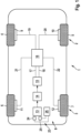
- FIG. 1 shows a simplified representation of a motor vehicle 1.
- the motor vehicle 1 has a front wheel axle 2 and a rear wheel axle 3.
- the front wheel axle 2 has a rotatably mounted first wheel 4 and a rotatably mounted second wheel 5.
- the rear axle 3 has a rotatably mounted third wheel 6 and a rotatably mounted fourth wheel 7.
- the motor vehicle 1 also has a braking system 8.
- the braking system 8 has a number of braking devices 9, 10, 11 and 12 corresponding to the number of wheels.
- the braking devices 9, 10, 11 and 12 are in Figure 1 shown only schematically. Each of the wheels 4, 5, 6 and 7 is assigned a different one of the braking devices 9, 10, 11 or 12.
- the braking devices 9, 10, 11 and 12 are designed to generate a friction braking torque in order to reduce the rotational speed of the wheel to which they are assigned.
- a first braking device 9 of the braking devices is designed to reduce the current To reduce the rotational speed of the first wheel 4.
- the first braking device 9 has a braking element connected to the first wheel 4 in a rotationally fixed manner and at least one braking body that can be pressed against the braking element.
- the braking devices 10, 11 and 12 correspond in terms of their design to the first braking device 9.
- the braking devices 10, 11 and 12 each have a braking element and at least one braking body that can be pressed against the braking element.
- the rotor is coupled to a gear device 14.
- the gear device 14 has at least one displaceably mounted element and is designed to convert a rotation of the rotor into a displacement of the displaceably mounted element.
- the gear device 14 has a spindle gear with a rotatably mounted spindle nut and a displaceably mounted spindle.
- the brake system 8 also has a master brake cylinder 15.
- the master brake cylinder 15 is designed as a tandem master brake cylinder 15, so that two hydraulic pistons are movably mounted in the master brake cylinder 15.
- the rotor is coupled to the master brake cylinder 15 by the transmission device 14 in such a way that the hydraulic pistons can be moved by rotating the rotor.
- the brake system 8 also has a hydraulic block 16.
- the master brake cylinder 15 is fluidically connected to the hydraulic block 16 by two input lines 17 and 18.
- the hydraulic block 16 is in turn fluidically connected to the wheel brake cylinders of the brake devices 9, 10, 11 and 12 by four output lines 19, 20, 21 and 22. If the hydraulic pistons are moved in an actuation direction, a pressure in the lines 17, 18, 19, 20, 21 and 22 Hydraulic fluid generates a clamping force F clamp acting on the brake bodies, by which the brake bodies are pressed against the respective brake elements.
- the clamping force can be generated by rotating the rotor.
- the level of the clamping force generated then corresponds to a rotation angle ⁇ of the rotor and a displacement path of the displaceably mounted element.
- the larger the rotation angle ⁇ the higher the clamping force F clamp generated.
- the level of the clamping force F clamp generated corresponds to the level of the friction braking torque. The higher the clamping force F clamp , the higher the friction braking torque.
- the motor vehicle 1 also has a device 23.
- the device 23 has a rotation angle sensor 24, which is assigned to the rotor and is designed to detect the rotation angle ⁇ of the rotor.
- the device 23 also has a current sensor 25, which is assigned to the motor winding and is designed to detect the level of the electrical motor current I Mot flowing through the motor winding.
- the device 23 has an evaluation device 26.
- the evaluation device 26 is connected to the rotation angle sensor 24 and the current sensor 25 in terms of communication technology, so that the detected rotation angle ⁇ and the level of the motor current I Mot are provided to the evaluation device 26.
- the evaluation device 26 is designed to determine the level of the generated clamping force F Spann as a function of the rotation angle ⁇ of the rotor on the one hand and the level of the motor current I Mot on the other.
- the evaluation device 26 is also designed to determine control signals for switches of a power electronics of the electric motor 13 and to control the switches depending on the control signals.
- the evaluation device 26 is designed as a control device 26. If a friction braking torque is to be generated by the braking devices 9, 10, 11 and 12, the evaluation device 26 controls the power electronics of the electric motor 13 in such a controlled manner that the generated clamping force F Spann corresponds to a predetermined target clamping force.
- the motor winding is thus supplied with the electric motor current I Mot in such a way that the generated clamping force F Spann of the corresponds to the specified target clamping force.
- the target clamping force is specified by actuation of a brake pedal of the motor vehicle 1 by a driver of the motor vehicle 1.
- Figure 2 shows a further embodiment of the motor vehicle 1.
- the Figure 2 The motor vehicle 1 shown differs from the one in Figure 1 illustrated motor vehicle 1 with regard to the design of the braking system 8.
- the Figure 2 The motor vehicle shown has the braking devices 9, 10, 11 and 12.
- the brake system 8 of the Figure 2 The motor vehicle 1 shown has a number of electric motors 13 corresponding to the number of braking devices 9, 10, 11 and 12.
- the braking system 8 has a number of transmission devices 14 corresponding to the number of braking devices 9, 10, 11 and 12.
- Each braking device 9, 10, 11 and 12 is assigned a different one of the electric motors 13 and a different one of the transmission devices 14.
- the rotors of the electric motors 13 are also coupled to the brake bodies of the brake devices 9, 10, 11 and 12 by the gear devices 14 in such a way that by applying a motor current I Mot to the motor windings of the electric motors 13, a clamping force F Spann can be generated, by which the brake bodies of the brake devices 9, 10, 11 and 12 are pressed against the respective brake elements.
- the gear devices 14 are each coupled directly to the brake bodies, i.e. without the interposition of a master brake cylinder.
- the device 23A of the Figure 2 The illustrated motor vehicle 1 has a number of angle of rotation sensors 24 corresponding to the number of electric motors 13, wherein each of the electric motors 13 is assigned a different one of the angle of rotation sensors 24.
- the device 23A also has a number of current sensors 25 corresponding to the number of electric motors 13, wherein each of the electric motors 13 is assigned a different one of the current sensors 25.
- the angle of rotation sensors 24 and the current sensors 25 are connected to the evaluation device 26A for communication purposes, so that the angle of rotation ⁇ detected by the angle of rotation sensors 24 and the motor currents I Mot detected by the current sensors 25 are provided to the evaluation device 26A.
- the evaluation device 26A of the Figure 2 The control unit of the motor vehicle 1 shown is designed to determine the level of the clamping forces F Spann generated by the electric motors 13 as a function of the angle of rotation ⁇ of the respective rotor on the one hand and the level of the respective motor current I Mot on the other hand.
- control device 26A is designed to determine control signals for switches of power electronics of the electric motors 13 and to control the switches depending on the control signals.
- the evaluation device 26A is designed to control the electric motors 13 independently of one another.
- the evaluation device 26A controls the power electronics in such a way that the clamping forces F clamp generated by the electric motors 13 each correspond to the predetermined target clamping force, as described above with reference to the evaluation device 26.
- Figure 4 shows a second characteristic curve L2.
- the second characteristic curve L2 describes the level of a clamping force ratio K F,I of the braking devices as a function of the motor current I Mot .
- the clamping force ratio K F,I decreases with an increase in the motor current I Mot .
- FIG. 5 An advantageous method for determining the level of the generated clamping force F Spann is explained.
- Figure 5 The process is illustrated using a flow chart. The process is illustrated using the evaluation device 26 of the Figure 1 However, the evaluation device 26A of the vehicle 1 shown in Figure 2 illustrated motor vehicle 1 is designed to carry out the method and to determine by means of the method the clamping force F clamp generated by the electric motors 13.
- the angle of rotation sensor 24 detects the current angle of rotation ⁇ of the rotor. In addition, the angle of rotation sensor 24 provides the detected angle of rotation ⁇ to the evaluation device 26.
- the current sensor 25 detects the level of the motor current I Mot . In addition, the current sensor 25 provides the detected level of the motor current I Mot to the evaluation device 26.
- At least steps S1 and S2 are carried out continuously so that a curve of the angle of rotation ⁇ and a curve of the motor current I Mot are provided to the evaluation device 26.
- a third step S3 the evaluation device 26 determines a clamping force ratio K F,I corresponding to the level of the motor current I Mot using the second characteristic curve L2 as a function of the level of the motor current I Mot .
- a correction situation is assumed if the braking devices 9, 10, 11 and 12 and the electric motor 13 are in a static state.
- the evaluation device 26 specifies a rotational speed threshold and a current change threshold.
- the evaluation device 26 determines, depending on the course of the rotation angle ⁇ is a rotational speed of the rotor and, depending on the course of the motor current I Mot, a motor current change in the motor current I Mot .
- the evaluation device 26 determines that the correction situation exists when the determined rotational speed of the rotor falls below the rotational speed threshold and the determined motor current change falls below the current change threshold.
- step S4 determines in step S4 that the correction situation does not exist.
- step S5 determines the level of the clamping force F Spann generated as a function of the angle of rotation ⁇ detected in step S1 using the first characteristic curve L1.
- the level of the motor current I Mot is not taken into account in this case.
- step S6 the evaluation device 26 determines a current-based angle of rotation ⁇ I of the rotor using the first characteristic curve L1 as a function of the current-based clamping force F Spann,I determined in the third step S3.
- a seventh step S7 the evaluation device 26 compares the current-based angle of rotation ⁇ I determined in step S6 with the angle of rotation ⁇ detected in step S1. If the detected angle of rotation ⁇ deviates from the current-based angle of rotation ⁇ I , the evaluation device 26 corrects the detected angle of rotation ⁇ . The evaluation device 26 therefore determines a corrected angle of rotation ⁇ korr . For example, a rotation angle that is less than the detected angle of rotation ⁇ is determined as the corrected angle of rotation ⁇ korr if the current-based angle of rotation ⁇ I is less than the detected angle of rotation ⁇ .
- the evaluation device 26 changes the first characteristic curve L1 depending on the corrected angle of rotation ⁇ corr .
- the evaluation device 26 thus determines a corrected first characteristic curve. If step S5 is carried out again, the evaluation device 26 then determines the generated clamping force F clamp as a function of the detected angle of rotation ⁇ using the corrected first characteristic curve.
Landscapes
- Engineering & Computer Science (AREA)
- Transportation (AREA)
- Mechanical Engineering (AREA)
- Braking Systems And Boosters (AREA)
- Regulating Braking Force (AREA)
- Electric Propulsion And Braking For Vehicles (AREA)
- Control Of Electric Motors In General (AREA)
Description
- Die Erfindung betrifft ein Verfahren zum Ermitteln einer Spannkraft einer Bremseinrichtung eines Kraftfahrzeugs, wobei das Kraftfahrzeug wenigstens ein drehbar gelagertes Rad und eine Bremsanlage mit zumindest einer Bremseinrichtung und zumindest einem Elektromotor aufweist, wobei die Bremseinrichtung ein drehfest mit dem Rad verbundenes Bremselement und zumindest einen gegen das Bremselement pressbaren Bremskörper aufweist, wobei der Elektromotor eine Motorwicklung und einen drehbar gelagerten Rotor aufweist, wobei der Rotor durch eine Getriebeeinrichtung derart mit dem Bremskörper gekoppelt ist, dass durch eine Drehung des Rotors eine Spannkraft erzeugbar ist, durch die der Bremskörper gegen das Bremselement gepresst wird, wobei der Rotor durch eine Beaufschlagung der Motorwicklung mit einem elektrischen Motorstrom drehbar ist, wobei ein Drehwinkel des Rotors und/oder ein Verschiebeweg eines verschiebbar gelagerten Elementes der Getriebeeinrichtung ermittelt werden, und wobei eine Höhe der erzeugten Spannkraft in Abhängigkeit von dem Drehwinkel und/oder dem Verschiebeweg ermittelt wird.
- Außerdem betrifft die Erfindung ein Verfahren zum Betreiben eines Kraftfahrzeugs.
- Ferner betrifft die Erfindung eine Vorrichtung zum Ermitteln einer Spannkraft, mit einem Auswertegerät.
- Ein Kraftfahrzeug weist üblicherweise mehrere drehbar gelagerte Räder auf. Um eine Fahrtgeschwindigkeit des Kraftfahrzeugs zu verringern, weist das Kraftfahrzeug in der Regel eine Bremsanlage mit zumindest einer Bremseinrichtung auf. Die Bremseinrichtung ist einem der Räder des Kraftfahrzeugs zugeordnet und dazu ausgebildet, ein Reibbremsmoment zu erzeugen, durch das eine aktuelle Drehgeschwindigkeit des Rads verringert wird. Hierzu weist die Bremseinrichtung ein drehfest mit dem Rad verbundenes Bremselement wie zum Beispiel eine Bremsscheibe und zumindest einen gegen das Bremselement pressbaren Bremskörper auf. Wird der Bremskörper gegen das Bremselement gepresst, so wird das Reibbremsmoment erzeugt. Vorzugsweise weist die Bremsanlage mehrere Bremseinrichtungen auf, wobei jede der Bremseinrichtungen jeweils einem anderen der Räder zugeordnet ist.
- Immer häufiger weisen Bremsanlagen zur Betätigung der Bremseinrichtung zudem einen Elektromotor mit einer insbesondere mehrphasigen Motorwicklung und einem drehbar gelagerten Rotor auf. Der Rotor ist dabei durch eine Getriebeeinrichtung derart mit dem Bremskörper gekoppelt, dass durch eine Drehung des Rotors eine Spannkraft erzeugbar ist, durch die der Bremskörper gegen das Bremselement gepresst wird. Die Drehung des Rotors wird also durch die Getriebeeinrichtung in eine Verschiebung des Bremskörpers umgewandelt. Eine Höhe der dabei erzeugten Spannkraft korrespondiert mit einer Höhe des Reibbremsmomentes. Je höher die Spannkraft ist, desto höher ist auch das Reibbremsmoment. Der Rotor ist dabei durch eine Beaufschlagung der Motorwicklung mit einem elektrischen Motorstrom drehbar.
- Aus dem Stand der Technik sind Verfahren zum Ermitteln der Höhe der erzeugten Spannkraft bekannt. Die Kenntnis der Spannkraft ermöglicht eine vorteilhafte Regelung des Elektromotors. Dabei ist es bekannt, einen Drehwinkel des Rotors und/oder einen Verschiebeweg eines verschiebbar gelagerten Elementes der Getriebeeinrichtung zu ermitteln. Der Drehwinkel und der Verschiebeweg korrespondieren mit der Höhe der Spannkraft. Je größer der Drehwinkel beziehungsweise der Verschiebeweg ist, desto größer ist auch die erzeugte Spannkraft. Entsprechend wird die Höhe der Spannkraft dann in Abhängigkeit von dem Drehwinkel und/oder dem Verschiebeweg ermittelt.
- Die Patentschrift
KR 101 338 433 B1 EP 3 156 294 A1 undUS 2017/321773 A1 beschrieben. - Das erfindungsgemäße Verfahren mit den Merkmalen des Anspruchs 1 hat den Vorteil, dass die Genauigkeit gesteigert wird, mit der die Höhe der erzeugten Spannkraft ermittelt wird. Erfindungsgemäß ist hierzu vorgesehen, dass eine Höhe des Motorstroms ermittelt wird, und dass die Höhe der Spannkraft in Abhängigkeit von der Höhe des Motorstroms ermittelt wird. Bei schlupfbehafteten Getriebeeinrichtungen führt die alleinige Berücksichtigung des Drehwinkels und/oder des Verschiebewegs mit zunehmendem absoluten Drehwinkel beziehungsweise Verschiebeweg zu Ungenauigkeiten beim Ermitteln der Höhe der erzeugten Spannkraft. Diese Ungenauigkeiten werden durch die zusätzliche Berücksichtigung der Höhe des Motorstroms zumindest teilweise kompensiert. Auch die Höhe des Motorstroms korrespondiert zumindest in bestimmten Betriebspunkten des Elektromotors mit der Höhe der erzeugten Spannkraft. Beispielsweise steigt die Spannkraft mit einer Steigerung des Motorstroms. Vorzugsweise wird der Motorstrom erfasst beziehungsweise gemessen. Auch darunter ist ein Ermitteln des Motorstroms zu verstehen. Es ist dann also eine Sensoreinrichtung vorhanden, die dazu ausgebildet ist, die Höhe des Motorstroms zu erfassen. Alternativ dazu wird vorzugsweise ein Parameter erfasst beziehungsweise gemessen, der mit der Höhe des Motorstroms korrespondiert, beispielsweise eine elektrische Motorspannung der Motorwicklung. Die Höhe des Motorstroms wird dann in Abhängigkeit von dem erfassten Parameter ermittelt.
- Gemäß einer bevorzugten Ausführungsform ist vorgesehen, dass die Höhe der Spannkraft in Abhängigkeit von einer ersten Kennlinie ermittelt wird, die die Spannkraft in Abhängigkeit von dem Drehwinkel oder dem Verschiebeweg beschreibt. Anhand der ersten Kennlinie ist die erzeugte Spannkraft präzise ermittelbar. Mittels der ersten Kennlinie kann einer Vielzahl von Drehwinkeln beziehungsweise Verschiebewegen jeweils eine entsprechende Spannkraft zugeordnet werden.
- Vorzugsweise wird die erste Kennlinie in Abhängigkeit von der ermittelten Höhe des Motorstroms verändert. Hierdurch wird eine auswertungstechnisch einfache Berücksichtigung der Höhe des Motorstroms erreicht. Beispielsweise wird eine Steigung der ersten Kennlinie in Abhängigkeit von der ermittelten Höhe des Motorstroms verändert.
- Erfindungsgemäß ist vorgesehen, dass in Abhängigkeit von der Höhe des Motorstroms einerseits und dem ermittelten Drehwinkel andererseits ein korrigierter Drehwinkel ermittelt wird, wobei die Höhe der Spannkraft in Abhängigkeit von dem korrigierten Drehwinkel ermittelt wird, und/oder dass in Abhängigkeit von der Höhe des Motorstroms einerseits und dem ermittelten Verschiebeweg andererseits ein korrigierter Verschiebeweg ermittelt wird, wobei die Höhe der Spannkraft in Abhängigkeit von dem korrigierten Verschiebeweg ermittelt wird. Der ursprünglich ermittelte Drehwinkel beziehungsweise der ursprünglich ermittelte Verschiebeweg werden also in Abhängigkeit von der ermittelten Höhe des Motorstroms korrigiert. Beispielsweise wird in Abhängigkeit von der Höhe des Motorstroms ein Korrekturfaktor ermittelt und der ermittelte Drehwinkel beziehungsweise der ermittelte Verschiebeweg wird zur Korrektur mit dem Korrekturfaktor multipliziert. Entsprechend werden dann der korrigierte Drehwinkel beziehungsweise der korrigierte Verschiebeweg dem Ermitteln der Höhe der Spannkraft zugrunde gelegt. Beispielsweise wird die Höhe der Spannkraft in Abhängigkeit von dem korrigierten Drehwinkel beziehungsweise dem korrigierten Verschiebeweg mittels der ersten Kennlinie ermittelt.
- Gemäß einer bevorzugten Ausführungsform ist vorgesehen, dass in Abhängigkeit von der Höhe des Motorstroms und einer zweiten Kennlinie, die eine Spannkraftübersetzung der Bremseinrichtung in Abhängigkeit von der Höhe des Motorstroms beschreibt, eine strombasierte Spannkraft ermittelt wird, wobei die erste Kennlinie in Abhängigkeit von der strombasierten Spannkraft verändert wird, und/oder wobei der korrigierte Drehwinkel und/oder der korrigierte Verschiebeweg in Abhängigkeit von der strombasierten Spannkraft ermittelt werden. Durch die Verwendung der zweiten Kennlinie wird eine präzise Berücksichtigung der ermittelten Höhe des Motorstroms beim Ermitteln der Spannkraft erreicht. Mittels der zweiten Kennlinie kann einer Vielzahl von Motorstromwerten jeweils eine entsprechende Spannkraftübersetzung zugeordnet werden. Die strombasierte Spannkraft kann dann beispielsweise mittels der Gleichung

- Erfindungsgemäß wird überwacht, ob eine Korrektursituation vorliegt, wobei der korrigierte Drehwinkel und/oder der korrigierte Verschiebeweg nur bei Vorliegen der Korrektursituation ermittelt werden. Vorzugsweise wird die Kennlinie nur bei Vorliegen der Korrektursituation in Abhängigkeit von der Höhe des Motorstroms verändert. Unter einer Korrektursituation ist eine Situation zu verstehen, in der davon auszugehen ist, dass durch die Berücksichtigung der Höhe des Motorstroms eine gewünschte Genauigkeitssteigerung beim Ermitteln der Höhe der erzeugten Spannkraft erreicht wird. Liegt die Korrektursituation nicht vor, so bleibt die ermittelte Höhe des Motorstroms beim Ermitteln der Höhe der erzeugten Spannkraft vorzugsweise unberücksichtigt.
- Gemäß einer bevorzugten Ausführungsform ist vorgesehen, dass eine Drehgeschwindigkeitsschwelle vorgegeben wird, wobei bei Vorliegen einer die Drehgeschwindigkeitsschwelle unterschreitenden Drehgeschwindigkeit des Rotors festgestellt wird, dass die Korrektursituation vorliegt, und/oder dass eine Verschiebegeschwindigkeitsschwelle vorgegeben wird, wobei bei Vorliegen einer die Verschiebegeschwindigkeitsschwelle unterschreitenden Verschiebegeschwindigkeit des Elementes festgestellt wird, dass die Korrektursituation vorliegt. Es wird dabei davon ausgegangen, dass die Korrektursituation vorliegt, wenn sich die Bremseinrichtung beziehungsweise der Elektromotor in einem statischen Zustand befinden, wenn sich also der Zustand der Bremseinrichtung und des Elektromotors nicht mehr oder nur wenig verändert. Dies ist anhand der Drehgeschwindigkeit beziehungsweise der Verschiebegeschwindigkeit zuverlässig feststellbar.
- Vorzugsweise wird eine Stromänderungsschwelle vorgegeben, wobei bei Vorliegen einer die Stromänderungsschwelle unterschreitenden Motorstromänderung festgestellt wird, dass die Korrektursituation vorliegt. Wie vorstehend erwähnt, liegt die Korrektursituation vor, wenn sich der Elektromotor in einem statischen Zustand befindet. Demgemäß ist das Vorliegen der Korrektursituation auch in Abhängigkeit von der Motorstromänderung des Motorstroms zuverlässig feststellbar.
- Die Erfindung betrifft außerdem ein Verfahren zum Betreiben eines Kraftfahrzeugs, wobei das Kraftfahrzeug wenigstens ein drehbar gelagertes Rad und eine Bremsanlage mit zumindest einer Bremseinrichtung und zumindest einem Elektromotor aufweist, wobei die Bremseinrichtung ein drehfest mit dem Rad verbundenes Bremselement und zumindest einen gegen das Bremselement pressbaren Bremskörper aufweist, wobei der Elektromotor eine Motorwicklung und einen drehbar gelagerten Rotor aufweist, wobei der Rotor durch eine Getriebeeinrichtung derart mit dem Bremskörper gekoppelt ist, dass durch eine Drehung des Rotors eine Spannkraft erzeugbar ist, durch die der Bremskörper gegen das Bremselement gepresst wird, wobei der Rotor durch eine Beaufschlagung der Motorwicklung mit einem elektrischen Motorstrom drehbar ist, wobei eine Höhe der erzeugten Spannkraft ermittelt wird, und wobei die Motorwicklung derart mit dem Motorstrom beaufschlagt wird, dass die erzeugte Spannkraft einer vorgegebenen Soll-Spannkraft entspricht. Das Verfahren zum Betreiben des Kraftfahrzeugs zeichnet sich mit den Merkmalen des Anspruchs 8 dadurch aus, dass die Höhe der Spannkraft durch das erfindungsgemäße Verfahren zum Ermitteln der Spannkraft ermittelt wird. Auch daraus ergeben sich die bereits genannten Vorteile. Weitere bevorzugte Merkmale und Merkmalskombinationen ergeben sich aus dem zuvor Beschriebenen sowie aus den Ansprüchen.
- Die erfindungsgemäße Vorrichtung zum Ermitteln einer Spannkraft einer Bremseinrichtung eines Kraftfahrzeugs, wobei das Kraftfahrzeug wenigstens ein drehbar gelagertes Rad und eine Bremsanlage mit zumindest einer Bremseinrichtung und zumindest einem Elektromotor aufweist, wobei die Bremseinrichtung ein drehfest mit dem Rad verbundenes Bremselement und zumindest einen gegen das Bremselement pressbaren Bremskörper aufweist, wobei der Elektromotor eine Motorwicklung und einen drehbar gelagerten Rotor aufweist, wobei der Rotor durch eine Getriebeeinrichtung derart mit dem Bremskörper gekoppelt ist, dass durch eine Drehung des Rotors eine Spannkraft erzeugbar ist, durch die der Bremskörper gegen das Bremselement gepresst wird, und wobei der Rotor durch eine Beaufschlagung der Motorwicklung mit einem elektrischen Motorstrom drehbar ist, zeichnet sich mit den Merkmalen des Anspruchs 9 durch ein Auswertegerät aus, das speziell dazu hergerichtet ist, bei bestimmungsgemäßem Gebrauch das erfindungsgemäße Verfahren zum Ermitteln der Spannkraft durchzuführen. Auch daraus ergeben sich die bereits genannten Vorteile. Weitere bevorzugte Merkmale und Merkmalskombinationen ergeben sich aus dem zuvor Beschriebenen sowie aus den Ansprüchen.
- Gemäß einer bevorzugten Ausführungsform ist die Getriebeeinrichtung unmittelbar beziehungsweise direkt mit dem Bremskörper gekoppelt. Insofern liegt das verschiebbar gelagerte Element oder ein weiteres verschiebbar gelagertes Element der Getriebeeinrichtung zumindest bei einer Betätigung der Bremseinrichtung bezogen auf eine Verschiebeachse, entlang der der Bremskörper verschiebbar ist, axial direkt an dem Bremskörper an. Auf eine hydraulische Verbindung zwischen der Getriebeeinrichtung und dem Bremskörper wird dabei verzichtet. Beispielsweise weist die Getriebeeinrichtung ein Planetenwälzgetriebe auf, wobei es sich bei dem verschiebbar gelagerten Element dann um eine Planetenwälzgewindespindel handelt. Üblicherweise ist mehreren Rädern des Kraftfahrzeugs jeweils eine andere Bremseinrichtung zugeordnet. Vorzugsweise ist dann jeder der Bremseinrichtungen jeweils ein anderer Elektromotor und jeweils eine andere Getriebeeinrichtung zugeordnet. Das Auswertegerät ist dann dazu ausgebildet, die durch die verschiedenen Elektromotoren erzeugten Spannkräfte mittels des erfindungsgemäßen Verfahrens zu ermitteln.
- Gemäß einer weiteren bevorzugten Ausführungsform ist die Getriebeeinrichtung mit einem Hauptbremszylinder der Bremsanlage derart gekoppelt, dass bei einer Beaufschlagung der Motorwicklung mit dem Motorstrom ein in dem Hauptbremszylinder verschiebbar gelagerter Hydraulikkolben betätigt wird. Der Hauptbremszylinder ist fluidtechnisch derart mit dem Bremskörper verbunden, dass der Bremskörper bei einer Betätigung des Hydraulikkolbens gegen das Bremselement gepresst wird. Insofern ist die Getriebeeinrichtung gemäß dieser Ausführungsform mittelbar beziehungsweise indirekt mit dem Bremskörper gekoppelt.
- Im Folgenden wird die Erfindung anhand der Zeichnungen näher erläutert. Dazu zeigen
- Figur 1
- ein Kraftfahrzeug in einer vereinfachten Darstellung,
- Figur 2
- ein weiteres Kraftfahrzeug in einer vereinfachten Darstellung,
- Figur 3
- eine erste Kennlinie,
- Figur 4
- eine zweite Kennlinie und
- Figur 5
- ein Verfahren zum Ermitteln einer Spannkraft.
- Figur ein zeigt in einer vereinfachten Darstellung ein Kraftfahrzeug 1. Das Kraftfahrzeug 1 weist eine Vorderradachse 2 und eine Hinterradachse 3 auf. Die Vorderradachse 2 weist ein drehbar gelagertes erstes Rad 4 und ein drehbar gelagertes zweites Rad 5 auf. Die Hinterachse 3 weist ein drehbar gelagertes drittes Rads 6 und ein drehbar gelagertes viertes Rad 7 auf.
- Das Kraftfahrzeug 1 weist außerdem eine Bremsanlage 8 auf. Die Bremsanlage 8 weist eine der Anzahl der Räder entsprechende Anzahl an Bremseinrichtungen 9, 10, 11 und 12 auf. Die Bremseinrichtungen 9, 10, 11 und 12 sind in
Figur 1 lediglich schematisch dargestellt. Jedem der Räder 4, 5, 6 und 7 ist jeweils eine andere der Bremseinrichtungen 9, 10, 11 oder 12 zugeordnet. Die Bremseinrichtungen 9, 10, 11 und 12 sind dazu ausgebildet, ein Reibbremsmoment zu erzeugen, um die Drehgeschwindigkeit des Rads zu verringern, dem sie zugeordnet sind. Beispielsweise ist eine erste Bremseinrichtung 9 der Bremseinrichtungen dazu ausgebildet, die aktuelle Drehgeschwindigkeit des ersten Rads 4 zu verringern. Hierzu weist die erste Bremseinrichtung 9 ein drehfest mit dem ersten Rad 4 verbundenes Bremselement und zumindest einen gegen das Bremselement pressbaren Bremskörper auf. Die Bremseinrichtungen 10, 11 und 12 entsprechen bezüglich ihrer Ausgestaltung der ersten Bremseinrichtung 9. Insofern weisen auch die Bremseinrichtungen 10, 11 und 12 jeweils ein Bremselement und zumindest einen Bremskörper auf, der gegen das Bremselement pressbar ist. - Die Bremsanlage 8 weist außerdem einen Elektromotor 13 auf. Auch der Elektromotor 13 ist in
Figur 1 lediglich schematisch dargestellt. Der Elektromotor 13 weist einen drehbar gelagerten Rotor und eine Motorwicklung auf. Dabei ist der Rotor durch eine Beaufschlagung der Motorwicklung mit einem elektrischen Motorstrom IMot drehbar. - Der Rotor ist mit einer Getriebeeinrichtung 14 gekoppelt. Die Getriebeeinrichtung 14 weist zumindest ein verschiebbar gelagertes Element auf und ist dazu ausgebildet, eine Drehung des Rotors in eine Verschiebung des verschiebbar gelagerten Elementes zu wandeln. Beispielsweise weist die Getriebeeinrichtung 14 hierzu ein Spindelgetriebe mit einer drehbar gelagerten Spindelmutter und einer verschiebbar gelagerten Spindel auf.
- Die Bremsanlage 8 weist außerdem einen Hauptbremszylinder 15 auf. Vorliegend ist der Hauptbremszylinder 15 als Tandem-Hauptbremszylinder 15 ausgebildet, sodass in dem Hauptbremszylinder 15 zwei Hydraulikkolben verschiebbar gelagert sind. Der Rotor ist durch die Getriebeeinrichtung 14 derart mit dem Hauptbremszylinder 15 gekoppelt, dass die Hydraulikkolben durch eine Drehung des Rotors verschiebbar sind.
- Die Bremsanlage 8 weist außerdem einen Hydraulikblock 16 auf. Der Hauptbremszylinders 15 ist durch zwei Eingangsleitungen 17 und 18 fluidtechnisch mit dem Hydraulikblock 16 verbunden. Der Hydraulikblock 16 ist wiederum durch vier Ausgangsleitungen 19, 20, 21 und 22 fluidtechnisch mit den Radbremszylindern der Bremseinrichtungen 9, 10, 11 und 12 verbunden. Werden die Hydraulikkolben in eine Betätigungsrichtung verschoben, so wird durch eine in den Leitungen 17, 18, 19, 20, 21 und 22 vorhandene Hydraulikflüssigkeit eine auf die Bremskörper wirkende Spannkraft FSpann erzeugt, durch die die Bremskörper gegen die jeweiligen Bremselemente gepresst werden.
- Weil der Rotor durch die Getriebeeinrichtung 14 mit den Hydraulikkolben gekoppelt ist, ist die Spannkraft durch die Drehung des Rotors erzeugbar. Eine Höhe der erzeugten Spannkraft korrespondiert dann mit einem Drehwinkel ϕ des Rotors und einem Verschiebeweg des verschiebbar gelagerten Elementes. Je größer der Drehwinkel ϕ ist, desto höher ist auch die erzeugte Spannkraft FSpann. Weiterhin korrespondiert die Höhe der erzeugten Spannkraft FSpann mit der Höhe des Reibbremsmomentes. Je höher die Spannkraft FSpann ist, desto höher ist auch das Reibbremsmoment.
- Das Kraftfahrzeug 1 weist außerdem eine Vorrichtung 23 auf. Die Vorrichtung 23 weist einen Drehwinkelsensor 24 auf, der dem Rotor zugeordnet und dazu ausgebildet ist, den Drehwinkel ϕ des Rotors zu erfassen. Die Vorrichtung 23 weist außerdem einen Stromsensor 25 auf, der der Motorwicklung zugeordnet und dazu ausgebildet ist, die Höhe des durch die Motorwicklung fließenden elektrischen Motorstroms IMot zu erfassen. Zudem weist die Vorrichtung 23 ein Auswertegerät 26 auf. Das Auswertegerät 26 ist kommunikationstechnisch mit dem Drehwinkelsensor 24 und dem Stromsensor 25 verbunden, sodass dem Auswertegerät 26 der erfasste Drehwinkel ϕ und die Höhe des Motorstroms IMot bereitgestellt werden. Das Auswertegerät 26 ist dazu ausgebildet, die Höhe der erzeugten Spannkraft FSpann in Abhängigkeit von dem Drehwinkel ϕ des Rotors einerseits und der Höhe des Motorstroms IMot andererseits zu ermitteln.
- Das Auswertegerät 26 ist außerdem dazu ausgebildet, Ansteuersignale für Schalter einer Leistungselektronik des Elektromotors 13 zu ermitteln und die Schalter in Abhängigkeit von den Ansteuersignalen anzusteuern. Insofern ist das Auswertegerät 26 als Steuergerät 26 ausgebildet. Soll durch die Bremseinrichtungen 9, 10, 11 und 12 ein Reibbremsmoment erzeugt werden, so steuert das Auswertegerät 26 die Leistungselektronik des Elektromotors 13 derart geregelt an, dass die erzeugte Spannkraft FSpann einer vorgegebenen Soll-Spannkraft entspricht. Die Motorwicklung wird also derart mit dem elektrischen Motorstrom IMot beaufschlagt, dass die erzeugte Spannkraft FSpann der vorgegebenen Soll-Spannkraft entspricht. Beispielsweise wird die Soll-Spannkraft durch Betätigung eines Bremspedals des Kraftfahrzeugs 1 durch einen Fahrer des Kraftfahrzeugs 1 vorgegeben.
-
Figur 2 zeigt ein weiteres Ausführungsbeispiel des Kraftfahrzeugs 1. Das inFigur 2 dargestellte Kraftfahrzeug 1 unterscheidet sich von dem inFigur 1 dargestellten Kraftfahrzeugs 1 im Hinblick auf die Ausgestaltung der Bremsanlage 8. Auch das inFigur 2 dargestellte Kraftfahrzeug weist die Bremseinrichtungen 9, 10, 11 und 12 auf. - Die Bremsanlage 8 des in
Figur 2 dargestellten Kraftfahrzeugs 1 weist eine der Anzahl an Bremseinrichtungen 9, 10, 11 und 12 entsprechende Anzahl an Elektromotoren 13 auf. Zudem weist die Bremsanlage 8 eine der Anzahl an Bremseinrichtungen 9, 10, 11 und 12 entsprechende Anzahl an Getriebeeinrichtungen 14 auf. Jeder Bremseinrichtung 9, 10, 11 und 12 ist jeweils ein anderer der Elektromotoren 13 und eine andere der Getriebeeinrichtungen 14 zugeordnet. - Auch die Rotoren der Elektromotoren 13 sind durch die Getriebeeinrichtungen 14 derart mit den Bremskörpern der Bremseinrichtungen 9, 10, 11 und 12 gekoppelt, dass durch eine Beaufschlagung der Motorwicklungen der Elektromotoren 13 mit einem Motorstrom IMot jeweils eine Spannkraft FSpann erzeugbar ist, durch die die Bremskörper der Bremseinrichtungen 9, 10, 11 und 12 gegen die jeweiligen Bremselemente gepresst werden. Die Getriebeeinrichtungen 14 sind dabei jeweils direkt mit den Bremskörpern gekoppelt, also ohne Zwischenschaltung eines Hauptbremszylinders.
- Die Vorrichtung 23A des in
Figur 2 dargestellten Kraftfahrzeugs 1 weist eine der Anzahl an Elektromotoren 13 entsprechende Anzahl an Drehwinkelsensoren 24 auf, wobei jedem der Elektromotoren 13 jeweils ein anderer der Drehwinkelsensoren 24 zugeordnet ist. - Die Vorrichtung 23A weist außerdem eine der Anzahl an Elektromotoren 13 entsprechende Anzahl an Stromsensoren 25 auf, wobei jedem der Elektromotoren 13 jeweils ein anderer der Stromsensoren 25 zugeordnet ist.
- Die Drehwinkelsensoren 24 und die Stromsensoren 25 sind kommunikationstechnisch mit dem Auswertegerät 26A verbunden, sodass dem Auswertegerät 26A die durch die Drehwinkelsensoren 24 erfassten Drehwinkel ϕ sowie die durch die Stromsensoren 25 erfassten Motorströme IMot bereitgestellt werden.
- Das Auswertegerät 26A des in
Figur 2 dargestellten Kraftfahrzeugs 1 ist dazu ausgebildet, die Höhe der durch die Elektromotoren 13 erzeugten Spannkräfte FSpann in Abhängigkeit von dem Drehwinkel ϕ des jeweiligen Rotors einerseits und der Höhe des jeweiligen Motorstroms IMot andererseits zu ermitteln. - Zudem ist das Ansteuergerät 26A dazu ausgebildet, Ansteuersignale für Schalter von Leistungselektroniken der Elektromotoren 13 zu ermitteln und die Schalter in Abhängigkeit von den Ansteuersignalen anzusteuern. Das Auswertegerät 26A ist dabei dazu ausgebildet, die Elektromotoren 13 unabhängig voneinander anzusteuern. Das Auswertegerät 26A steuert dabei die Leistungselektroniken derart an, dass die durch die Elektromotoren 13 erzeugten Spannkräfte FSpann jeweils der vorgegebenen Soll-Spannkraft entsprechen, wie vorstehend mit Bezug auf das Auswertegerät 26 beschrieben.
-
Figur 3 zeigt eine erste Kennlinie L1. Die erste Kennlinie L1 beschreibt die Höhe der erzeugten Spannkraft FSpann in Abhängigkeit von dem Drehwinkel ϕ des Rotors. Wie ausFigur 3 ersichtlich ist, steigt die Spannkraft FSpann mit einer Steigerung des Drehwinkels ϕ. -
Figur 4 zeigt eine zweite Kennlinie L2. Die zweite Kennlinie L2 beschreibt die Höhe einer Spannkraftübersetzung KF,I der Bremseinrichtungen in Abhängigkeit von dem Motorstrom IMot. Wie ausFigur 4 ersichtlich ist, verringert sich die Spannkraftübersetzung KF,I mit einer Steigerung des Motorstroms IMot. - Wie zuvor erwähnt steuert das Auswertegerät 26 den Elektromotor 13 derart an, dass die erzeugte Spannkraft FSpann der vorgegebenen Soll-Spannkraft entspricht. Entsprechend steuert das Auswertegerät 26A die Elektromotoren 13 derart an, dass die jeweils erzeugte Spannkraft FSpann der vorgegebenen Soll-Spannkraft entspricht.
- Im Folgenden wird mit Bezug auf
Figur 5 ein vorteilhaftes Verfahren zum Ermitteln der Höhe der erzeugten Spannkraft FSpann erläutert. Hierzu zeigtFigur 5 das Verfahren anhand eines Flussdiagramms. Das Verfahren wird beispielhaft anhand des Auswertegeräts 26 des inFigur 1 dargestellten Kraftfahrzeugs 1 beschrieben. Allerdings ist auch das Auswertegerät 26A des inFigur 2 dargestellten Kraftfahrzeugs 1 dazu ausgebildet, das Verfahren durchzuführen und mittels des Verfahrens die durch die Elektromotoren 13 jeweils erzeugte Spannkraft FSpann zu ermitteln. - In einem ersten Schritt S1 erfasst der Drehwinkelsensor 24 den aktuellen Drehwinkel ϕ des Rotors. Zudem stellt der Drehwinkelsensor 24 den erfassten Drehwinkel ϕ dem Auswertegerät 26 bereit.
- In einem zweiten Schritt S2 erfasst der Stromsensor 25 die Höhe des Motorstroms IMot. Zudem stellt der Stromsensor 25 die erfasste Höhe des Motorstroms IMot dem Auswertegerät 26 bereit.
- Zumindest die Schritte S1 und S2 werden laufend durchgeführt, sodass dem Auswertegerät 26 ein Verlauf des Drehwinkels ϕ und ein Verlauf des Motorstroms IMot bereitgestellt werden.
- In einem dritten Schritt S3 ermittelt das Auswertegerät 26 in Abhängigkeit von der Höhe des Motorstroms IMot mittels der zweiten Kennlinie L2 eine mit der Höhe des Motorstroms IMot korrespondierende Spannkraftübersetzung KF,I. In Abhängigkeit von der ermittelten Spannkraftübersetzung KF,I ermittelt das Auswertegerät 26 dann in dem Schritt S3 mittels der Gleichung F Spann,I = KF,I (IMot ) × IMot eine strombasierte Spannkraft FSpann,I.
- In einem vierten Schritt S4 überprüft das Auswertegerät 26, ob eine Korrektursituation vorliegt. Von einer Korrektursituation wird ausgegangen, wenn sich die Bremseinrichtungen 9, 10, 11 und 12 und der Elektromotor 13 in einem statischen Zustand befinden. Hierzu gibt Auswertegerät 26 eine Drehgeschwindigkeitsschwelle und eine Stromänderungsschwelle vor. Zudem ermittelt das Auswertegerät 26 in Abhängigkeit von dem Verlauf des Drehwinkels ϕ eine Drehgeschwindigkeit des Rotors und in Abhängigkeit von dem Verlauf des Motorstroms IMot eine Motorstromänderung des Motorstroms IMot. Das Auswertegerät 26 stellt dann fest, dass die Korrektursituation vorliegt, wenn die ermittelte Drehgeschwindigkeit des Rotors die Drehgeschwindigkeitsschwelle unterschreitet und die ermittelte Motorstromänderung die Stromänderungsschwelle unterschreitet.
- Stellt das Auswertegerät 26 in dem Schritt S4 fest, dass die Korrektursituation nicht vorliegt, so wird auf einen fünften Schritt S5 verwiesen. In dem fünften Schritt S5 ermittelt dann das Auswertegerät 26 die Höhe der erzeugten Spannkraft FSpann in Abhängigkeit von dem in dem Schritt S1 erfassten Drehwinkel ϕ mittels der ersten Kennlinie L1. Die Höhe des Motorstroms IMot bleibt dabei unberücksichtigt.
- Stellt das Auswertegerät 26 in dem Schritt S4 jedoch fest, dass die Korrektursituation vorliegt, so wird auf einen sechsten Schritt S6 verwiesen. In dem sechsten Schritt S6 ermittelt das Auswertegerät 26 dann in Abhängigkeit von der in dem dritten Schritt S3 ermittelten strombasierten Spannkraft FSpann,I mittels der ersten Kennlinie L1 einen strombasierten Drehwinkel ϕI des Rotors.
- In einem siebten Schritt S7 vergleicht das Auswertegerät 26 den in dem Schritt S6 ermittelten strombasierten Drehwinkel ϕI mit dem in dem Schritt S1 erfassten Drehwinkel ϕ. Weicht der erfasste Drehwinkel ϕ von dem strombasierten Drehwinkel ϕI ab, so korrigiert das Auswertegerät 26 den erfassten Drehwinkel ϕ. Das Auswertegerät 26 ermittelt also einen korrigierten Drehwinkel ϕkorr. Beispielsweise wird als korrigierter Drehwinkel ϕkorr ein den erfassten Drehwinkel ϕ unterschreitender Drehwinkel ermittelt, wenn der strombasierte Drehwinkel ϕI den erfassten Drehwinkel ϕ unterschreitet.
- In einem achten Schritt S8 ermittelt das Auswertegerät 26 dann die erzeugte Spannkraft FSpann in Abhängigkeit von dem korrigierten Drehwinkel ϕkorr mittels der ersten Kennlinie L1.
- Vorzugsweise verändert das Auswertegerät 26 in Abhängigkeit von dem korrigierten Drehwinkel ϕkorr die erste Kennlinie L1. Das Auswertegerät 26 ermittelt also eine korrigierte erste Kennlinie. Wird der Schritt S5 erneut durchgeführt, so ermittelt das Auswertegerät 26 dann die erzeugte Spannkraft FSpann in Abhängigkeit von dem erfassten Drehwinkel ϕ mittels der korrigierten ersten Kennlinie.
- Wie zuvor erwähnt korrespondiert der Drehwinkel ϕ des Rotors mit dem Verschiebeweg des verschiebbar gelagerten Elementes der Getriebeeinrichtung 14. Gemäß einem weiteren Ausführungsbeispiel des Verfahrens wird der Verschiebeweg des Elementes erfasst und anstelle des erfassten Drehwinkels ϕ dem Ermitteln der erzeugten Spannkraft FSpann zugrunde gelegt. Beispielsweise wird dann eine erste Kennlinie L1 verwendet, die die erzeugte Spannkraft FSpann in Abhängigkeit von dem Verschiebeweg des Elementes beschreibt.
Claims (9)
- Verfahren zum Ermitteln einer Spannkraft einer Bremseinrichtung eines Kraftfahrzeugs, wobei das Kraftfahrzeug (1) wenigstens ein drehbar gelagertes Rad (4) und eine Bremsanlage (8) mit zumindest einer Bremseinrichtung (9) und zumindest einem Elektromotor (13) aufweist, wobei die Bremseinrichtung (9) ein drehfest mit dem Rad (4) verbundenes Bremselement und zumindest einen gegen das Bremselement pressbaren Bremskörper aufweist, wobei der Elektromotor (13) eine Motorwicklung und einen drehbar gelagerten Rotor aufweist, wobei der Rotor durch eine Getriebeeinrichtung (14) derart mit dem Bremskörper gekoppelt ist, dass durch eine Drehung des Rotors eine Spannkraft (FSpann) erzeugbar ist, durch die der Bremskörper gegen das Bremselement gepresst wird, wobei der Rotor durch eine Beaufschlagung der Motorwicklung mit einem elektrischen Motorstrom (IMot) drehbar ist, wobei ein Drehwinkel (ϕ) des Rotors und/oder ein Verschiebeweg eines verschiebbar gelagerten Elementes der Getriebeeinrichtung (14) ermittelt werden, wobei eine Höhe der erzeugten Spannkraft (FSpann) in Abhängigkeit von dem Drehwinkel (ϕ) und/oder dem Verschiebeweg ermittelt wird, wobei eine Höhe des Motorstroms (IMot) ermittelt wird, und wobei die Höhe der Spannkraft (FSpann) in Abhängigkeit von der Höhe des Motorstroms (IMot) ermittelt wird, dadurch gekennzeichnet, dass überwacht wird, ob eine Korrektursituation vorliegt, in der sich die Bremseinrichtung (9) und/oder der Elektromotor (13) in einem statischen Zustand befinden, dass nur bei Vorliegen der Korrektursituation in Abhängigkeit von der Höhe des Motorstroms (IMot) einerseits und dem ermittelten Drehwinkel (ϕ) andererseits ein korrigierter Drehwinkel (ϕkorr) ermittelt und die Höhe der Spannkraft (FSpann) in Abhängigkeit von dem korrigierten Drehwinkel (ϕkorr) ermittelt wird, und/oder dass nur bei Vorliegen der Korrektursituation in Abhängigkeit von der Höhe des Motorstroms (IMot) einerseits und dem ermittelten Verschiebeweg andererseits ein korrigierter Verschiebeweg ermittelt und die Spannkraft (FSpann) in Abhängigkeit von dem korrigierten Verschiebeweg ermittelt wird.
- Verfahren nach Anspruch 1, dadurch gekennzeichnet, dass die Höhe der Spannkraft (FSpann) in Abhängigkeit von einer ersten Kennlinie (L1) ermittelt wird, die die Spannkraft (FSpann) in Abhängigkeit von dem Drehwinkel (ϕ) oder dem Verschiebeweg beschreibt.
- Verfahren nach Anspruch 2, dadurch gekennzeichnet, dass die erste Kennlinie (L1) in Abhängigkeit von der Höhe des Motorstroms (IMot) verändert wird.
- Verfahren nach einem der Ansprüche 2 und 3, dadurch gekennzeichnet, dass in Abhängigkeit von der Höhe des Motorstroms (IMot) und einer zweiten Kennlinie (L2), die eine Spannkraftübersetzung (KF,I) der Bremseinrichtung (9) in Abhängigkeit von der Höhe des Motorstroms (IMot) beschreibt, eine strombasierte Spannkraft (FSpann,I) ermittelt wird, wobei die erste Kennlinie (L1) in Abhängigkeit von der strombasierten Spannkraft (FSpann,I) verändert wird, und/oder wobei der korrigierte Drehwinkel (ϕkorr) und/oder der korrigierte Verschiebeweg in Abhängigkeit von der strombasierten Spannkraft (FSpann,I) ermittelt werden.
- Verfahren nach einem der Ansprüche 2 bis 4, dadurch gekennzeichnet, dass die erste Kennlinie (L1) nur bei Vorliegen der Korrektursituation in Abhängigkeit von der Höhe des Motorstroms (IMot) verändert wird.
- Verfahren nach einem der vorhergehenden Ansprüche, dadurch gekennzeichnet, dass eine Drehgeschwindigkeitsschwelle vorgegeben wird, wobei bei Vorliegen einer die Drehgeschwindigkeitsschwelle unterschreitenden Drehgeschwindigkeit des Rotors festgestellt wird, dass die Korrektursituation vorliegt, und/oder dass eine Verschiebegeschwindigkeitsschwelle vorgegeben wird, wobei bei Vorliegen einer die Verschiebegeschwindigkeitsschwelle unterschreitenden Verschiebegeschwindigkeit des Elementes festgestellt wird, dass die Korrektursituation vorliegt.
- Verfahren nach einem der vorhergehenden Ansprüche, dadurch gekennzeichnet, dass eine Stromänderungsschwelle vorgegeben wird, wobei bei Vorliegen einer die Stromänderungsschwelle unterschreitenden Motorstromänderung festgestellt wird, dass die Korrektursituation vorliegt.
- Verfahren zum Betreiben eines Kraftfahrzeugs, wobei das Kraftfahrzeug (1) wenigstens ein drehbar gelagertes Rad (4) und eine Bremsanlage (8) mit zumindest einer Bremseinrichtung (9) und zumindest einem Elektromotor (13) aufweist, wobei die Bremseinrichtung (9) ein drehfest mit dem Rad (4) verbundenes Bremselement und zumindest einen gegen das Bremselement pressbaren Bremskörper aufweist, wobei der Elektromotor (13) eine Motorwicklung und einen drehbar gelagerten Rotor aufweist, wobei der Rotor durch eine Getriebeeinrichtung (14) derart mit dem Bremskörper gekoppelt ist, dass durch eine Drehung des Rotors eine Spannkraft (FSpann) erzeugbar ist, durch die der Bremskörper gegen das Bremselement gepresst wird, wobei der Rotor durch eine Beaufschlagung der Motorwicklung mit einem elektrischen Motorstrom (IMot) drehbar ist, wobei eine Höhe der erzeugten Spannkraft (FSpann) ermittelt wird, und wobei die Motorwicklung derart mit dem Motorstrom (IMot) beaufschlagt wird, dass die erzeugte Spannkraft (FSpann) einer vorgegebenen Soll-Spannkraft entspricht, dadurch gekennzeichnet, dass die Höhe der Spannkraft (FSpann) durch ein Verfahren gemäß einem der Ansprüche 1 bis 7 ermittelt wird.
- Vorrichtung zum Ermitteln einer Spannkraft einer Bremseinrichtung eines Kraftfahrzeugs, wobei das Kraftfahrzeug (1) wenigstens ein drehbar gelagertes Rad (4) und eine Bremsanlage (8) mit zumindest einer Bremseinrichtung (9) und zumindest einem Elektromotor (13) aufweist, wobei die Bremseinrichtung (9) ein drehfest mit dem Rad (4) verbundenes Bremselement und zumindest einen gegen das Bremselement pressbaren Bremskörper aufweist, wobei der Elektromotor (13) eine Motorwicklung und einen drehbar gelagerten Rotor aufweist, wobei der Rotor durch eine Getriebeeinrichtung (14) derart mit dem Bremskörper gekoppelt ist, dass durch eine Drehung des Rotors eine Spannkraft (FSpann) erzeugbar ist, durch die der Bremskörper gegen das Bremselement gepresst wird, und wobei der Rotor durch eine Beaufschlagung der Motorwicklung mit einem elektrischen Motorstrom(IMot) drehbar ist, gekennzeichnet durch ein Auswertegerät (26, 26A), das speziell dazu hergerichtet ist, bei bestimmungsgemäßem Gebrauch das Verfahren gemäß einem der Ansprüche 1 bis 7 durchzuführen.
Applications Claiming Priority (2)
| Application Number | Priority Date | Filing Date | Title |
|---|---|---|---|
| DE102020208853.5A DE102020208853A1 (de) | 2020-07-15 | 2020-07-15 | Verfahren zum Ermitteln einer Spannkraft einer Bremseinrichtung eines Kraftfahrzeugs, Verfahren zum Betreiben eines Kraftfahrzeugs, Vorrichtung |
| PCT/EP2021/067114 WO2022012886A1 (de) | 2020-07-15 | 2021-06-23 | Verfahren und vorrichtung zum ermitteln einer spannkraft einer bremseinrichtung eines kraftfahrzeugs |
Publications (2)
| Publication Number | Publication Date |
|---|---|
| EP4182196A1 EP4182196A1 (de) | 2023-05-24 |
| EP4182196B1 true EP4182196B1 (de) | 2025-02-26 |
Family
ID=76796936
Family Applications (1)
| Application Number | Title | Priority Date | Filing Date |
|---|---|---|---|
| EP21737583.1A Active EP4182196B1 (de) | 2020-07-15 | 2021-06-23 | Verfahren und vorrichtung zum ermitteln einer spannkraft einer bremseinrichtung eines kraftfahrzeugs |
Country Status (6)
| Country | Link |
|---|---|
| US (1) | US20230249657A1 (de) |
| EP (1) | EP4182196B1 (de) |
| JP (1) | JP7781849B2 (de) |
| CN (1) | CN116615365B (de) |
| DE (1) | DE102020208853A1 (de) |
| WO (1) | WO2022012886A1 (de) |
Families Citing this family (1)
| Publication number | Priority date | Publication date | Assignee | Title |
|---|---|---|---|---|
| JP2025075722A (ja) * | 2023-10-31 | 2025-05-15 | 株式会社アドヴィックス | 電動制動装置 |
Citations (1)
| Publication number | Priority date | Publication date | Assignee | Title |
|---|---|---|---|---|
| EP3156294B1 (de) * | 2015-10-14 | 2018-06-06 | Akebono Brake Industry Co., Ltd. | Verfahren zur steuerung eines feststellbremssystems |
Family Cites Families (10)
| Publication number | Priority date | Publication date | Assignee | Title |
|---|---|---|---|---|
| DE10005758B4 (de) * | 2000-02-09 | 2011-02-24 | Volkswagen Ag | Verfahren zur Bestimmung des Verschleißzustandes eines Bremsbelages sowie entsprechende elektromechanische Bremsenanordnung |
| DE102011004772A1 (de) * | 2011-02-25 | 2012-08-30 | Robert Bosch Gmbh | Verfahren zum Einstellen der von einer Feststellbremse ausgeübten Klemmkraft |
| KR101338433B1 (ko) * | 2011-11-16 | 2013-12-10 | 현대자동차주식회사 | 전동 브레이크장치 및 그것의 제어방법 |
| JP6309322B2 (ja) * | 2014-03-27 | 2018-04-11 | Ntn株式会社 | 電動ブレーキ装置 |
| DE102015206034A1 (de) * | 2015-04-02 | 2016-10-06 | Robert Bosch Gmbh | Verfahren und Vorrichtung zum Betreiben eines Bremssystems eines Fahrzeugs, Bremssystem |
| DE102015209021A1 (de) * | 2015-05-18 | 2016-11-24 | Robert Bosch Gmbh | Verfahren zum Betätigen einer Feststellbremse in einem Fahrzeug |
| JP6133360B2 (ja) * | 2015-06-01 | 2017-05-24 | Ntn株式会社 | 電動ブレーキ装置 |
| KR101836628B1 (ko) * | 2016-05-03 | 2018-03-08 | 현대자동차주식회사 | 전동식 브레이크 장치 및 그 제어 방법 |
| DE102016226325A1 (de) * | 2016-12-29 | 2018-07-05 | Robert Bosch Gmbh | Steuervorrichtung und Verfahren zum Betreiben eines elektromechanischen Bremskraftverstärkers eines Bremssystems eines Fahrzeugs |
| KR102858131B1 (ko) * | 2020-06-19 | 2025-09-11 | 에이치엘만도 주식회사 | 전기 기계식 브레이크 시스템 및 그 제어 방법 |
-
2020
- 2020-07-15 DE DE102020208853.5A patent/DE102020208853A1/de active Pending
-
2021
- 2021-06-23 EP EP21737583.1A patent/EP4182196B1/de active Active
- 2021-06-23 JP JP2023501265A patent/JP7781849B2/ja active Active
- 2021-06-23 US US18/004,807 patent/US20230249657A1/en active Pending
- 2021-06-23 CN CN202180062712.4A patent/CN116615365B/zh active Active
- 2021-06-23 WO PCT/EP2021/067114 patent/WO2022012886A1/de not_active Ceased
Patent Citations (1)
| Publication number | Priority date | Publication date | Assignee | Title |
|---|---|---|---|---|
| EP3156294B1 (de) * | 2015-10-14 | 2018-06-06 | Akebono Brake Industry Co., Ltd. | Verfahren zur steuerung eines feststellbremssystems |
Also Published As
| Publication number | Publication date |
|---|---|
| KR20230047393A (ko) | 2023-04-07 |
| JP2023547976A (ja) | 2023-11-15 |
| WO2022012886A1 (de) | 2022-01-20 |
| CN116615365A (zh) | 2023-08-18 |
| JP7781849B2 (ja) | 2025-12-08 |
| EP4182196A1 (de) | 2023-05-24 |
| CN116615365B (zh) | 2026-03-24 |
| DE102020208853A1 (de) | 2022-01-20 |
| US20230249657A1 (en) | 2023-08-10 |
Similar Documents
| Publication | Publication Date | Title |
|---|---|---|
| DE19632251B4 (de) | Vorrichtung und Verfahren zur Lenkung eines Kraftfahrzeuges | |
| DE102007030441B4 (de) | Bremssystem für ein Kraftahrzeug und Verfahren zum Betreiben eines Bremssystems eines Kraftfahrzeugs | |
| EP3580101B1 (de) | Bremsmotor-steuergerät, bremssystem für ein fahrzeug mit einem elektrischen bremsmotor und verfahren zur ansteuerung des bremsmotorsteuergeräts | |
| DE112020003056T5 (de) | Elektrische Bremsvorrichtung, Bremssteuervorrichtung und Steuerparameterkalibrierungsverfahren | |
| DE112021001103T5 (de) | Fahrzeugsteuerungsvorrichtung, Fahrzeugsteuerungsverfahren und Fahrzeugsteuerungssystem | |
| WO2012130494A1 (de) | Verfahren zum einstellen einer feststellbremse in einem fahrzeug | |
| DE102022204291A1 (de) | Verfahren zum Betreiben eines Steer-by-Wire-Lenksystems und Steer-by-Wire-Lenksystem | |
| EP4182196B1 (de) | Verfahren und vorrichtung zum ermitteln einer spannkraft einer bremseinrichtung eines kraftfahrzeugs | |
| DE102016214195A1 (de) | Verfahren zur Funktionsprüfung einer elektromechanischen Bremsvorrichtung | |
| DE112014003646B4 (de) | Verfahren zur Bestimmung einer Position eines sich linear bewegenden Aktorgetriebes in einem Aktorsystem, insbesondere einem Kupplungsbetätigungssystem eines Kraftfahrzeuges und ein Aktorsystem | |
| EP3247597B1 (de) | Verfahren und vorrichtung zum betreiben einer parkbremse | |
| DE102010032043A1 (de) | Lenksystem und Verfahren zum Betreiben des Lenksystems | |
| WO2018121952A1 (de) | Steuervorrichtung und verfahren zum betreiben eines elektromechanischen bremskraftverstärkers eines bremssystems eines fahrzeugs | |
| DE102017210893A1 (de) | Verfahren und eine Vorrichtung zum Betreiben einer automatisierten Feststellbremse | |
| DE102016223826A1 (de) | Verfahren und Vorrichtung zum Betreiben eines hydraulischen Bremssystems, Bremssystem | |
| WO2011003644A1 (de) | Vorrichtung und verfahren zum überwachen einer feststellbremse | |
| EP3562721A1 (de) | Auswerteelektronik und verfahren zum schätzen eines hauptbremszylinderdrucks in einem mit einem elektromechanischen bremskraftverstärker ausgestatteten bremssystem eines fahrzeugs | |
| DE10356096A1 (de) | Verfahren und Vorrichtung zum Betätigen einer Feststellbremsanlage für Fahrzeuge | |
| WO2017021061A1 (de) | Verfahren zum überprüfen der parkbremskraft in einem fahrzeug | |
| DE19751397B4 (de) | Verfahren und Vorrichtung zum Betrieb eines Überlagerungs- bzw. Lenksystems, insbesondere für ein Kraftfahrzeug | |
| WO2020030376A1 (de) | Verfahren und steuergerät zum betreiben eines hydraulischen bremssystems, bremssystem und kraftfahrzeug | |
| WO2009000620A1 (de) | Verfahren zur einstellung eines lenksystems in einem fahrzeug | |
| DE102018104324A1 (de) | Zweirad mit einem an einer Vorderradaufhängung angreifenden sensorgesteuerten Aktuator zur Korrektur einer Schräglage des Zweirads | |
| EP4217244B1 (de) | Verfahren zum betreiben eines elektromotors, steuergerät, kolbenpumpe | |
| DE19934496B4 (de) | Bremssystem für ein Flurförderzeug |
Legal Events
| Date | Code | Title | Description |
|---|---|---|---|
| STAA | Information on the status of an ep patent application or granted ep patent |
Free format text: STATUS: UNKNOWN |
|
| STAA | Information on the status of an ep patent application or granted ep patent |
Free format text: STATUS: THE INTERNATIONAL PUBLICATION HAS BEEN MADE |
|
| PUAI | Public reference made under article 153(3) epc to a published international application that has entered the european phase |
Free format text: ORIGINAL CODE: 0009012 |
|
| STAA | Information on the status of an ep patent application or granted ep patent |
Free format text: STATUS: REQUEST FOR EXAMINATION WAS MADE |
|
| 17P | Request for examination filed |
Effective date: 20230215 |
|
| AK | Designated contracting states |
Kind code of ref document: A1 Designated state(s): AL AT BE BG CH CY CZ DE DK EE ES FI FR GB GR HR HU IE IS IT LI LT LU LV MC MK MT NL NO PL PT RO RS SE SI SK SM TR |
|
| DAV | Request for validation of the european patent (deleted) | ||
| DAX | Request for extension of the european patent (deleted) | ||
| GRAP | Despatch of communication of intention to grant a patent |
Free format text: ORIGINAL CODE: EPIDOSNIGR1 |
|
| STAA | Information on the status of an ep patent application or granted ep patent |
Free format text: STATUS: GRANT OF PATENT IS INTENDED |
|
| INTG | Intention to grant announced |
Effective date: 20241024 |
|
| GRAS | Grant fee paid |
Free format text: ORIGINAL CODE: EPIDOSNIGR3 |
|
| GRAA | (expected) grant |
Free format text: ORIGINAL CODE: 0009210 |
|
| STAA | Information on the status of an ep patent application or granted ep patent |
Free format text: STATUS: THE PATENT HAS BEEN GRANTED |
|
| AK | Designated contracting states |
Kind code of ref document: B1 Designated state(s): AL AT BE BG CH CY CZ DE DK EE ES FI FR GB GR HR HU IE IS IT LI LT LU LV MC MK MT NL NO PL PT RO RS SE SI SK SM TR |
|
| REG | Reference to a national code |
Ref country code: GB Ref legal event code: FG4D Free format text: NOT ENGLISH |
|
| REG | Reference to a national code |
Ref country code: CH Ref legal event code: EP |
|
| REG | Reference to a national code |
Ref country code: DE Ref legal event code: R096 Ref document number: 502021006794 Country of ref document: DE |
|
| REG | Reference to a national code |
Ref country code: IE Ref legal event code: FG4D Free format text: LANGUAGE OF EP DOCUMENT: GERMAN |
|
| REG | Reference to a national code |
Ref country code: NL Ref legal event code: MP Effective date: 20250226 |
|
| PG25 | Lapsed in a contracting state [announced via postgrant information from national office to epo] |
Ref country code: RS Free format text: LAPSE BECAUSE OF FAILURE TO SUBMIT A TRANSLATION OF THE DESCRIPTION OR TO PAY THE FEE WITHIN THE PRESCRIBED TIME-LIMIT Effective date: 20250526 |
|
| PG25 | Lapsed in a contracting state [announced via postgrant information from national office to epo] |
Ref country code: FI Free format text: LAPSE BECAUSE OF FAILURE TO SUBMIT A TRANSLATION OF THE DESCRIPTION OR TO PAY THE FEE WITHIN THE PRESCRIBED TIME-LIMIT Effective date: 20250226 |
|
| PG25 | Lapsed in a contracting state [announced via postgrant information from national office to epo] |
Ref country code: PL Free format text: LAPSE BECAUSE OF FAILURE TO SUBMIT A TRANSLATION OF THE DESCRIPTION OR TO PAY THE FEE WITHIN THE PRESCRIBED TIME-LIMIT Effective date: 20250226 |
|
| PG25 | Lapsed in a contracting state [announced via postgrant information from national office to epo] |
Ref country code: ES Free format text: LAPSE BECAUSE OF FAILURE TO SUBMIT A TRANSLATION OF THE DESCRIPTION OR TO PAY THE FEE WITHIN THE PRESCRIBED TIME-LIMIT Effective date: 20250226 |
|
| REG | Reference to a national code |
Ref country code: LT Ref legal event code: MG9D |
|
| PG25 | Lapsed in a contracting state [announced via postgrant information from national office to epo] |
Ref country code: NO Free format text: LAPSE BECAUSE OF FAILURE TO SUBMIT A TRANSLATION OF THE DESCRIPTION OR TO PAY THE FEE WITHIN THE PRESCRIBED TIME-LIMIT Effective date: 20250526 Ref country code: IS Free format text: LAPSE BECAUSE OF FAILURE TO SUBMIT A TRANSLATION OF THE DESCRIPTION OR TO PAY THE FEE WITHIN THE PRESCRIBED TIME-LIMIT Effective date: 20250626 |
|
| PG25 | Lapsed in a contracting state [announced via postgrant information from national office to epo] |
Ref country code: NL Free format text: LAPSE BECAUSE OF FAILURE TO SUBMIT A TRANSLATION OF THE DESCRIPTION OR TO PAY THE FEE WITHIN THE PRESCRIBED TIME-LIMIT Effective date: 20250226 |
|
| PG25 | Lapsed in a contracting state [announced via postgrant information from national office to epo] |
Ref country code: HR Free format text: LAPSE BECAUSE OF FAILURE TO SUBMIT A TRANSLATION OF THE DESCRIPTION OR TO PAY THE FEE WITHIN THE PRESCRIBED TIME-LIMIT Effective date: 20250226 |
|
| PG25 | Lapsed in a contracting state [announced via postgrant information from national office to epo] |
Ref country code: PT Free format text: LAPSE BECAUSE OF FAILURE TO SUBMIT A TRANSLATION OF THE DESCRIPTION OR TO PAY THE FEE WITHIN THE PRESCRIBED TIME-LIMIT Effective date: 20250626 Ref country code: LV Free format text: LAPSE BECAUSE OF FAILURE TO SUBMIT A TRANSLATION OF THE DESCRIPTION OR TO PAY THE FEE WITHIN THE PRESCRIBED TIME-LIMIT Effective date: 20250226 |
|
| PGFP | Annual fee paid to national office [announced via postgrant information from national office to epo] |
Ref country code: FR Payment date: 20250626 Year of fee payment: 5 |
|
| PG25 | Lapsed in a contracting state [announced via postgrant information from national office to epo] |
Ref country code: BG Free format text: LAPSE BECAUSE OF FAILURE TO SUBMIT A TRANSLATION OF THE DESCRIPTION OR TO PAY THE FEE WITHIN THE PRESCRIBED TIME-LIMIT Effective date: 20250226 Ref country code: GR Free format text: LAPSE BECAUSE OF FAILURE TO SUBMIT A TRANSLATION OF THE DESCRIPTION OR TO PAY THE FEE WITHIN THE PRESCRIBED TIME-LIMIT Effective date: 20250527 |
|
| PGFP | Annual fee paid to national office [announced via postgrant information from national office to epo] |
Ref country code: AT Payment date: 20250721 Year of fee payment: 5 |
|
| PG25 | Lapsed in a contracting state [announced via postgrant information from national office to epo] |
Ref country code: SE Free format text: LAPSE BECAUSE OF FAILURE TO SUBMIT A TRANSLATION OF THE DESCRIPTION OR TO PAY THE FEE WITHIN THE PRESCRIBED TIME-LIMIT Effective date: 20250226 |
|
| PG25 | Lapsed in a contracting state [announced via postgrant information from national office to epo] |
Ref country code: SM Free format text: LAPSE BECAUSE OF FAILURE TO SUBMIT A TRANSLATION OF THE DESCRIPTION OR TO PAY THE FEE WITHIN THE PRESCRIBED TIME-LIMIT Effective date: 20250226 |
|
| PG25 | Lapsed in a contracting state [announced via postgrant information from national office to epo] |
Ref country code: DK Free format text: LAPSE BECAUSE OF FAILURE TO SUBMIT A TRANSLATION OF THE DESCRIPTION OR TO PAY THE FEE WITHIN THE PRESCRIBED TIME-LIMIT Effective date: 20250226 |
|
| PGFP | Annual fee paid to national office [announced via postgrant information from national office to epo] |
Ref country code: DE Payment date: 20250814 Year of fee payment: 5 |
|
| PGFP | Annual fee paid to national office [announced via postgrant information from national office to epo] |
Ref country code: IT Payment date: 20250630 Year of fee payment: 5 |
|
| PG25 | Lapsed in a contracting state [announced via postgrant information from national office to epo] |
Ref country code: EE Free format text: LAPSE BECAUSE OF FAILURE TO SUBMIT A TRANSLATION OF THE DESCRIPTION OR TO PAY THE FEE WITHIN THE PRESCRIBED TIME-LIMIT Effective date: 20250226 Ref country code: CZ Free format text: LAPSE BECAUSE OF FAILURE TO SUBMIT A TRANSLATION OF THE DESCRIPTION OR TO PAY THE FEE WITHIN THE PRESCRIBED TIME-LIMIT Effective date: 20250226 |
|
| PG25 | Lapsed in a contracting state [announced via postgrant information from national office to epo] |
Ref country code: RO Free format text: LAPSE BECAUSE OF FAILURE TO SUBMIT A TRANSLATION OF THE DESCRIPTION OR TO PAY THE FEE WITHIN THE PRESCRIBED TIME-LIMIT Effective date: 20250226 |
|
| PG25 | Lapsed in a contracting state [announced via postgrant information from national office to epo] |
Ref country code: SK Free format text: LAPSE BECAUSE OF FAILURE TO SUBMIT A TRANSLATION OF THE DESCRIPTION OR TO PAY THE FEE WITHIN THE PRESCRIBED TIME-LIMIT Effective date: 20250226 |
|
| REG | Reference to a national code |
Ref country code: DE Ref legal event code: R097 Ref document number: 502021006794 Country of ref document: DE |
|
| PLBE | No opposition filed within time limit |
Free format text: ORIGINAL CODE: 0009261 |
|
| STAA | Information on the status of an ep patent application or granted ep patent |
Free format text: STATUS: NO OPPOSITION FILED WITHIN TIME LIMIT |
|
| REG | Reference to a national code |
Ref country code: CH Ref legal event code: L10 Free format text: ST27 STATUS EVENT CODE: U-0-0-L10-L00 (AS PROVIDED BY THE NATIONAL OFFICE) Effective date: 20260107 |
|
| REG | Reference to a national code |
Ref country code: CH Ref legal event code: H13 Free format text: ST27 STATUS EVENT CODE: U-0-0-H10-H13 (AS PROVIDED BY THE NATIONAL OFFICE) Effective date: 20260127 |
|
| PG25 | Lapsed in a contracting state [announced via postgrant information from national office to epo] |
Ref country code: MC Free format text: LAPSE BECAUSE OF FAILURE TO SUBMIT A TRANSLATION OF THE DESCRIPTION OR TO PAY THE FEE WITHIN THE PRESCRIBED TIME-LIMIT Effective date: 20250226 |
|
| 26N | No opposition filed |
Effective date: 20251127 |
|
| PG25 | Lapsed in a contracting state [announced via postgrant information from national office to epo] |
Ref country code: LU Free format text: LAPSE BECAUSE OF NON-PAYMENT OF DUE FEES Effective date: 20250623 |
|
| GBPC | Gb: european patent ceased through non-payment of renewal fee |
Effective date: 20250623 |
|
| REG | Reference to a national code |
Ref country code: BE Ref legal event code: MM Effective date: 20250630 |
|
| PG25 | Lapsed in a contracting state [announced via postgrant information from national office to epo] |
Ref country code: GB Free format text: LAPSE BECAUSE OF NON-PAYMENT OF DUE FEES Effective date: 20250623 |
|
| PG25 | Lapsed in a contracting state [announced via postgrant information from national office to epo] |
Ref country code: IE Free format text: LAPSE BECAUSE OF NON-PAYMENT OF DUE FEES Effective date: 20250623 |
|
| PG25 | Lapsed in a contracting state [announced via postgrant information from national office to epo] |
Ref country code: BE Free format text: LAPSE BECAUSE OF NON-PAYMENT OF DUE FEES Effective date: 20250630 |
|
| PG25 | Lapsed in a contracting state [announced via postgrant information from national office to epo] |
Ref country code: CH Free format text: LAPSE BECAUSE OF NON-PAYMENT OF DUE FEES Effective date: 20250630 |