EP4182159B1 - Vorrichtung und verfahren zum trennen von miteinander vermischten stoffen unterschiedlicher fliessfähigkeit - Google Patents
Vorrichtung und verfahren zum trennen von miteinander vermischten stoffen unterschiedlicher fliessfähigkeit Download PDFInfo
- Publication number
- EP4182159B1 EP4182159B1 EP21745954.4A EP21745954A EP4182159B1 EP 4182159 B1 EP4182159 B1 EP 4182159B1 EP 21745954 A EP21745954 A EP 21745954A EP 4182159 B1 EP4182159 B1 EP 4182159B1
- Authority
- EP
- European Patent Office
- Prior art keywords
- hollow drum
- cooling medium
- hollow
- nozzle
- product
- Prior art date
- Legal status (The legal status is an assumption and is not a legal conclusion. Google has not performed a legal analysis and makes no representation as to the accuracy of the status listed.)
- Active
Links
Images
Classifications
-
- B—PERFORMING OPERATIONS; TRANSPORTING
- B30—PRESSES
- B30B—PRESSES IN GENERAL
- B30B15/00—Details of, or accessories for, presses; Auxiliary measures in connection with pressing
- B30B15/34—Heating or cooling presses or parts thereof
-
- A—HUMAN NECESSITIES
- A22—BUTCHERING; MEAT TREATMENT; PROCESSING POULTRY OR FISH
- A22C—PROCESSING MEAT, POULTRY, OR FISH
- A22C17/00—Other devices for processing meat or bones
- A22C17/04—Bone cleaning devices
-
- B—PERFORMING OPERATIONS; TRANSPORTING
- B30—PRESSES
- B30B—PRESSES IN GENERAL
- B30B9/00—Presses specially adapted for particular purposes
- B30B9/02—Presses specially adapted for particular purposes for squeezing-out liquid from liquid-containing material, e.g. juice from fruits, oil from oil-containing material
- B30B9/24—Presses specially adapted for particular purposes for squeezing-out liquid from liquid-containing material, e.g. juice from fruits, oil from oil-containing material using an endless pressing band
- B30B9/241—Presses specially adapted for particular purposes for squeezing-out liquid from liquid-containing material, e.g. juice from fruits, oil from oil-containing material using an endless pressing band co-operating with a drum or roller
Definitions
- the invention relates to a device designed and equipped for separating mixed materials of different flowability, comprising a frame, a hollow drum which is driven in rotation and mounted on the frame and has a perforated outer surface and at least one at least partially open end face, an endless press belt which can be pressed from the outside onto the outer surface by wrapping around part of the circumference of the hollow drum and which is driven in rotation, a product intake wedge formed by the press belt and hollow drum for guiding a product flow consisting of pressed material between the hollow drum and the press belt in an inlet region of the product flow into the device, a support device for the press belt with at least one support element which is arranged on the side of the press belt opposite the hollow drum, and a device for removing separated material pressed through the perforated outer surface into the hollow space of the hollow drum from the at least partially open end face of the hollow drum.
- the invention further relates to a method for separating mixed materials of different flowability, comprising the steps of: feeding a product stream consisting of pressed material into a product intake wedge, which is formed by a hollow drum with a perforated outer surface and a press belt, which rests on the hollow drum from the outside and wraps around part of the circumference, rotating the hollow drum and/or the press belt to draw the product stream between the hollow drum and the press belt, wherein the more easily flowing components of the product stream are pressed by means of the press belt as separating material through the perforation of the outer surface of the hollow drum into the hollow space of the hollow drum and are discharged from an at least partially open front side of the Hollow drum, while the heavier flowing components of the product stream remain on the outside surface of the hollow drum and are discharged separately.
- Substances, materials or products that differ from one another or whose composition differs from one another due to their different flow properties can be separated within the meaning of the invention.
- the possibility and/or necessity of separating mixed substances with different flow properties exists in particular in the production of foodstuffs of animal origin (such as separating the meat from the skin, tendons, bones or fish bones, etc.), from fruit and vegetables (such as separating the pulp from the peel, stalks, seeds or stones, etc.), in the processing of incorrectly packaged foodstuffs (such as separating butter or cheese from the packaging material) or the like.
- Specific application examples include pitting dates or unpacking cheese slices wrapped in foil.
- a product flow is conveyed from a product feed area with a product intake wedge between the pressing element, e.g. the pressing belt, and the hollow drum to a product output area.
- the product intake wedge is formed by the arrangement of the pressing belt to the hollow drum and leads to an (inlet) angle in the inlet area of the product flow into the device. Due to the rotating drive of the hollow drum and/or the rotating drive of the pressing belt, the product flow in the inlet area is drawn in between the hollow drum and the pressing belt in the conveying direction F, so that a distance/gap (filled with product flow) is created between the pressing belt and the hollow drum.
- the wrap between the pressing belt and the hollow drum creates a pressing area through which the product flow is conveyed.
- the materials with different flow properties are separated by pressing the more easily flowing materials, for example meat when processing products of animal origin, at least partially as a material to be separated, which in the case of products of animal origin consists of small threads of meat or small strands of meat, into the hollow drum and then removing them from there.
- the removal takes place via an at least partially open front side of the hollow drum, e.g. on the front side of the device, whereby the front side can also be defined as the back side. can.
- the more difficult-flowing substances again using the example of products of animal origin, such as bones, tendons, skin, etc., are collected in the conveying direction F of the product flow behind the hollow drum in the product output area and discharged.
- the portion of the product flow pressed into the interior of the hollow drum, i.e. into the hollow space, through the perforated outer surface M is discharged and sent for further processing.
- the residual flow of the product flow not pressed into the interior of the hollow drum through the perforated outer surface M usually adheres at least partially to the outside of the outer surface of the hollow drum. This residual flow adhering to the outside of the hollow drum can be removed, for example, using a stripping agent.
- the product flow is pressed from the outside against the perforated outer surface of the hollow drum by means of the press belt or any other pressing element. Under this pressure, the more easily flowing components of the product flow are pressed through the perforation of the outer surface into the inner cavity of the rotating hollow drum as material to be separated, while the more difficult-flowing components of the product flow remain on the outer surface of the hollow drum and are possibly discharged in the outlet area in the conveying direction F behind the hollow drum.
- considerable pressure and high friction occur, which heats up the product flow and in particular the material to be separated pressed or squeezed through the perforation.
- US 4 156 384 A shows a device according to the preamble of claim 1 and a method according to the preamble of claim 12.
- the invention is therefore based on the object of proposing a simple and reliable device for separating substances with different flow properties in a way that is gentle on the product.
- the object is also to propose a corresponding method.
- a device of the type mentioned at the outset in that the hollow drum is assigned a cooling device which is designed and set up to cool the material to be separated during processing using a cryogenic cooling medium, the cooling device being arranged in the hollow space of the hollow drum and comprising at least one nozzle which is connected to a reservoir of cooling medium via a supply line.
- processing in the context of the invention means that the material to be separated is cooled while still in the hollow drum, specifically when and directly when it swells out of the openings in the perforated outer surface of the hollow drum as a meat thread or meat strand.
- a continuous cooling chain can also be achieved during the separation process. At least a shortening of the interruption of the cooling chain for the separated goods is ensured by the cryogenic cooling medium acting directly on them during pressing, namely immediately when the separated goods arrive in the cavity.
- Cryogenic cooling media and in particular liquid cryogens enable efficient and rapid cooling of the separated goods when they hit their surface.
- Cryogenic gases can of course also be used, which liquefy under normal pressure at a critical temperature below room temperature. Since the separated goods with their narrow flesh threads or strands have a very large surface area, the cooling effect is correspondingly high, and particularly when exposed to liquid, cryogenic cooling medium. This enables a particularly gentle separation process for the product.
- the cooling of the material to be separated within the device compensates for or even overcompensates for heating due to mechanical stress, and a previously unattainable level of process control and product quality of the material to be separated is made available.
- the liquid cryogenic cooling medium can be easily and evenly distributed over the material to be separated.
- the number of nozzles can vary, as can their positioning in the cavity.
- the nozzles are preferably arranged on a support arm or the like, which projects through the at least partially open front side of the hollow drum, so that the rotation of the hollow drum is not impaired.
- the or each nozzle is connected to the reservoir via a flexible or rigid feed line.
- the or each nozzle can also be held in the cavity via a feed line that is then essentially rigid.
- Suitable containers for storing the liquid cryogens such as nitrogen, helium, argon, carbon dioxide or the like, can serve as a reservoir, and these containers feed the nozzles with the cooling medium via suitable feed lines.
- the or each nozzle is directed at least at the area of the inner surface of the hollow drum that is approximately opposite the area of the product intake wedge and/or the adjoining pressing area. This ensures significant cooling of the material to be separated directly at the processing location. Immediately upon formation or during formation of the thread-like/strand-like material to be separated, it is cooled in the interior of the hollow drum and can then be discharged in a cooled state.
- a preferred development is characterized in that the or each nozzle is designed as a flat jet nozzle which has a nozzle opening for forming a spray fan, such that the cooling medium emerging from the nozzle ensures a linear impact on the material to be separated pressed through the outer surface, extending over the entire width of the hollow drum.
- the or each flat jet nozzle ensures optimal introduction of the cooling medium.
- the line can also be made wider, so that a flat (rectangular) impact is possible.
- the free end of the spray fan has a width which corresponds at least to the width or depth of the inner surface of the hollow drum, so that every opening of the perforated outer surface is covered on the inside by the spray fan over the width/depth.
- the or each nozzle is assigned a cover which at least partially covers the or each nozzle.
- the preferably roof-shaped cover protects the nozzle or the nozzle opening from contamination by material to be separated falling from the inner surface of the hollow drum and also ensures that the spray fan has free access to the material to be separated.
- other designs for partially shielding the nozzle can also be used.
- the cooling device is associated with a device for collecting and removing the cooling medium fed into the hollow space of the hollow drum.
- the cryogenic cooling medium that hits the material to be separated in the liquid phase evaporates at least partially after impact or is converted into the gaseous phase.
- the heated or heating cooling medium is sucked off and removed accordingly in gaseous form, as an aerosol, mist, steam, smoke or even in liquid droplet form, in order to protect the environment and the operator.
- the device for collecting the cooling medium comprises at least one cover and an exhaust fan connected to the cover via exhaust air lines.
- the "used" cooling medium can be collected and discharged, for example, via an exhaust air line or an exhaust fan or the like.
- other extraction systems inside or outside the hollow drum can also be used.
- the or each supply line for supplying the cryogenic cooling medium to the or each nozzle comprises a measuring and/or control section.
- the measuring and/or control section can be formed within the supply line or replace it at least in sections.
- the measuring and/or control section can be used to monitor and control the inflow quantity, temperature, inflow speed, etc. of the cooling medium in order to achieve an optimal cooling effect.
- a desired temperature can be set for optimal process control and product quality.
- leaks in the supply line can also be monitored and evaluated for control purposes.
- Nitrogen is a readily available medium and has a high cooling capacity. Nitrogen is particularly advantageous because it creates an inert atmosphere inside the hollow drum and particularly in the area of the surface of the material being separated. Nitrogen can of course also be used in gaseous form for cooling. The oxygen (O 2 ) contained in the ambient air no longer reaches the product. This prevents certain chemical reactions in the material being separated, which means that the material being separated can be kept fresher. The inert atmosphere can also reduce the growth of germs on and in the material being separated.
- Carbon dioxide is also widely available and has a particularly high cooling effect. Carbon dioxide can of course also be used in gaseous form for cooling. Other cryogenic media can of course also be used.
- the device for removing the material to be separated expediently comprises a stripping element and/or an ejection screw. In individual designs, both components can be provided. However, either an ejection screw or a stripping element is preferably provided. Other means for releasing the material to be separated from the inner surface and/or for removing the material to be separated from the hollow drum can also be used.
- the stripping element advantageously comprises a product stripping edge and a product guide surface, the product guide surface being shaped and/or aligned in such a way that the product to be separated, which is stripped from the inner surface of the hollow drum by means of the product stripping edge, is guided in the direction of the open front side of the hollow drum.
- the stripping element can be arranged, for example, on a support that projects into the hollow space of the hollow drum.
- the stripping element is preferably arranged on a cross member that is preferably detachably attached to the frame, in such a way that the stripping element projects into the hollow drum through the at least partially open front side.
- the stripping element can be designed in several parts or in one part.
- the product to be separated by means of the stripping element or the ejection screw or any other The separated material discharged from the hollow drum can, for example, fall onto a preferably cooled tub, trough or any other conveying element and be transported away for further processing.
- the task is also solved by a method with the steps mentioned at the beginning in that the material to be separated pressed through the perforated outer surface into the hollow space of the hollow drum is cooled by means of a cryogenic cooling medium in the hollow drum, whereby the material to be separated is exposed to the cryogenic cooling medium directly and immediately during the separation process, i.e. when pressed through the outer surface and/or when removed from the hollow drum.
- a cryogenic cooling medium hits the material to be separated and cools it, whereby the cryogenic cooling medium gradually converts at least partially back into the gaseous phase after impact. Cooling therefore already takes place within the device as soon as the meat threads or meat strands press through the perforated outer surface into the interior of the hollow drum. This means that the cooling medium hits the material to be separated at the earliest possible time.
- cooling medium in a line shape across the entire width of the hollow drum onto the material being separated, which has been comminuted by the separation process. It is also possible to apply it over a large area, e.g. in a fan shape or similar.
- the material to be separated is exposed to nitrogen (N 2 ) as a cryogenic cooling medium.
- the material to be separated is exposed to carbon dioxide (CO 2 ) as a cryogenic cooling medium.
- the desired temperature of the material to be separated is controlled by supplying the cooling medium to the material to be separated.
- the cooling medium By applying the cooling medium to the material to be separated and controlling it in terms of temperature and/or quantity and/or speed, among other things, optimal process control and product quality can be achieved.
- cooling medium fed into the hollow space of the hollow drum is collected and drained away. Gases, aerosols, mist, steam, smoke or even droplets that are produced, i.e. all "unused" cooling medium, can be extracted in order to protect the environment and in particular the operators.
- the cooled material to be separated is stripped from the inner surface of the hollow drum and discharged from the hollow drum.
- the method is carried out with a device according to one or more of claims 1 to 11.
- the device shown in the drawing serves for separating meat on the one hand and bones, bone remnants, tendons, cartilage and the like on the other hand and has a number of preferred features. Other embodiments that have fewer or different features are not explicitly shown.
- the device can also be used in the same way for separating, for example, fruit pulp from seeds or for separating any other mixed materials with different flow properties.
- the device 10 shown is designed and configured to separate mixed substances of different flowability.
- the device 10 comprises a frame 11, a hollow drum 12 which is driven in rotation and mounted on the frame 11 and has a perforated outer surface M and at least one at least partially open end face S V , S H , an endless press belt 13 which can be pressed from the outside onto the outer surface by wrapping around part of the circumference of the hollow drum 12 and which is driven in rotation, a product intake wedge 14 formed by the press belt 13 and the hollow drum 12 for guiding a product flow consisting of material to be pressed between the hollow drum 12 and the press belt 13 in an inlet area E of the product flow into the device 10, a support device 15 for the press belt 13 with at least one support element 16 which is arranged on the side of the press belt 13 opposite the hollow drum 12, and a device 17 for discharging material through the perforated outer surface M into the cavity H of the hollow drum 12. pressed material to be separated from the at least partially open front side S V , S H of the hollow drum 12.
- the device 17 for removing the separated material from the hollow drum 12 can be an integral part of the hollow drum 12 or can be designed as a separate component.
- the front side Sv of the hollow drum 12 facing the front is designed to be open, the opposite front side S H is preferably designed to be closed.
- the opening 18 shown in the rear end wall S H serves to accommodate or support the hollow drum 12 on a drive shaft.
- the front and rear sides can also be swapped.
- This device 10 is characterized according to the invention in that the hollow drum 12 is assigned a cooling device 19 which is designed and configured to cool the material to be separated during processing by means of a cryogenic cooling medium 20.
- the frame 11 can be, for example, a closed or at least partially closed housing or a profile construction or the like. Preferably, the housing is essentially closed on all sides.
- the drive unit (not shown) for the hollow drum 12 and/or the press belt 13 is arranged on or in the frame 11.
- the drive unit can comprise a common drive or separate drive means.
- the axis of rotation R of the hollow drum 12 runs transversely to the conveying direction F of the product flow.
- holes/openings are formed, which can be arranged in different patterns and allow parts of the product flow, in particular the more easily flowing, soft and squeezable parts, to pass into the interior of the hollow drum 12.
- the hollow drum 12 is preferably provided with the openings over its entire depth or width B, which forms the working area.
- the press belt 13 is preferably made of an elastic material, e.g. rubber, polyurethane or the like, and is guided around several deflection elements 21.
- a deflection element 21 is designed and set up as a drive roller 22.
- the deflection element 21, which is placed behind the hollow drum 12 in the conveying direction F is the drive roller 22 in order to pull the press belt 13 and thus the product flow past the hollow drum 12.
- the drive roller 22 is simultaneously designed and set up as a pressure roller and/or tension roller for the press belt 13.
- the drive roller 22 is designed to be adjustable.
- the conveying of the product flow in the conveying direction F can be further supported by the hollow drum 12's own drive.
- stripping elements can be arranged in the inlet area E, i.e. above the product intake wedge 14, and/or in the outlet area A, i.e. in the conveying direction F behind the hollow drum 12, which is also referred to as a perforated drum.
- These stripping elements can be rigid, i.e. with a fixed distance to the hollow drum 12 or more precisely to the outer surface M, or variably controllable, i.e. variable in distance to the hollow drum 12 or more precisely to the outer surface M.
- the hollow drum 12 and the press belt 13 can be driven at the same speed.
- the hollow drum 12 and the press belt 13 can also be driven at different speeds. The speed difference can be controlled and/or regulated by means of a control and/or regulating device 23.
- the support device 15 can be a support chain or a support belt.
- the support device 15 is designed as a roller conveyor 24 which comprises a plurality of rollers 25 which are arranged one behind the other in the conveying direction F of the product flow and are at least partially spring-mounted.
- the cooling device 19 is arranged in the cavity H of the hollow drum 12 and comprises at least one nozzle 26, which is connected to a reservoir of cooling medium 20 (not explicitly shown) via a supply line 27.
- the supply line 27 is led out of the open end face Sv of the hollow drum 12.
- a cross member 28 is arranged in front of the open front side Sv, which is detachably attached to the frame 11.
- the supply line 27 is supported on the cross member 28, either directly or, as shown, indirectly via a type of splash guard 29, which at least partially covers the open front side Sv. Only a single nozzle 26 is shown in the drawing. However, several nozzles 26 can also be used optionally. Other options for fastening, supporting or resting the nozzle 26 and/or the supply line 27 are also possible.
- each nozzle 26 is directed towards the area of the inner surface of the hollow drum 12 which is approximately opposite the area of the product intake wedge 14 and/or the adjoining pressing area P.
- one nozzle 26 or nozzle bar can be directed towards the area of the product intake wedge 14 - as shown - while a second nozzle 26 or nozzle bar - not shown - is directed towards the pressing area P.
- the position and/or orientation of each nozzle 26 is, however, variable and changeable.
- the or each nozzle 26 is designed as a flat jet nozzle which has a nozzle opening for forming a spray fan 30 such that the cooling medium 20 emerging from the nozzle 26 ensures a linear impact on the material to be separated pressed through the outer surface M, extending over the entire depth/width B of the hollow drum 12.
- the spray fan 30 preferably covers the entire working width of the hollow drum 12.
- other designs of nozzles 26 with different nozzle openings can also be used.
- the or each nozzle 26 can be freely arranged in the cavity H.
- the or each nozzle 26 is assigned a cover 31 which at least partially covers the or each nozzle 26.
- the cover 31 is roof-shaped and is preferably also arranged on the cross member 28.
- the or each nozzle 26 is arranged below the cover 31 which is closed at the top and open at the bottom, so that the spray fan 30 can be formed without obstruction.
- the device 10 can comprise a device (not explicitly shown) for collecting and removing the cooling medium 20 fed into the cavity H of the hollow drum 12, which is associated with the cooling device 19.
- the device for collecting the cooling medium 20 can comprise at least one cover and an exhaust fan connected to the cover via exhaust air lines.
- the cover can, for example, enclose the entire area of the open front side Sv of the hollow drum 12, in the sense of covering it, so that suction of the used, at least predominantly gaseous cooling medium 20 is ensured.
- Other designs for suctioning the used cooling medium 20 from the cavity H of the hollow drum 12 can also be used.
- the or each supply line 27 for supplying the cryogenic cooling medium 20 to the or each nozzle 26 comprises a measuring and/or control section, which can be part of the device 10 or a higher-level unit.
- Liquid nitrogen (LN 2 ) is particularly preferably used as the cryogenic cooling medium 20.
- liquid carbon dioxide (LCO 2 ) can also be used as the cryogenic cooling medium 20.
- the cooling media can also be used in gaseous form.
- the material to be separated pressed through the outer surface M can be removed from the hollow drum 12 by itself, solely through the rotation of the hollow drum 12.
- the hollow drum 12 then forms the device 17 for removing the material to be separated.
- the device 17 for removing the material to be separated preferably comprises a stripping element 32 and/or an ejection screw.
- the drawing shows the preferred stripping element 32, which can also be detachably attached to the cross member 28.
- the stripping element 32 comprises a product stripping edge 33 and a product guide surface 34, the product guide surface 34 being shaped and/or aligned such that the material to be separated, which is stripped from the inner surface of the hollow drum 12 by means of the product stripping edge 33, is guided in the direction of the open front side Sv of the hollow drum 12.
- stripping element 32 which is preferably formed in one piece, and other constructions for removing the material to be separated from the hollow space H of the hollow drum 12 can also be used.
- the removed material to be separated can, for example, fall onto a discharge trough 35 or the like, which can optionally be cooled and is connected to a corresponding device for this purpose.
- a product stream consisting of pressed material is fed into a product intake wedge 14, which is formed by a hollow drum 12 with a perforated outer surface M and a press belt 13, which rests on the outside of the hollow drum 12 and wraps around part of the circumference.
- a product intake wedge 14 which is formed by a hollow drum 12 with a perforated outer surface M and a press belt 13, which rests on the outside of the hollow drum 12 and wraps around part of the circumference.
- the hollow drum 12 and the press belt 13 are driven in rotation to draw the product stream between the hollow drum 12 and the press belt 13.
- the hollow drum 12 is preferably (in the view according to Figure 1 ) is driven clockwise, while the drive roller 22 for the press belt (in the view according to the Figures 1 and 2 ) is driven anti-clockwise so that the hollow drum 12 and the press belt 13 have the same conveying direction F in the area of the wrap, i.e. in the pressing area P, where the speeds can be the same or different from one another.
- the more easily flowing components of the product flow are pressed by means of the pressing belt 13 as material to be separated through the perforation of the outer surface M of the hollow drum 12 into the inner cavity H of the hollow drum 12 and are discharged from an at least partially open front side S V and/or S H of the hollow drum 12, while the more difficult-flowing components of the product flow remain on the outside of the outer surface M of the hollow drum 12 and are discharged separately.
- the press belt 13 is supported on the side of the press belt 13 opposite the hollow drum 12 by a support device 15 comprising at least one support element 16.
- This method is characterized according to the invention in that the material to be separated, which is pressed through the perforated outer surface M into the cavity H of the hollow drum 12, is cooled by means of a cryogenic cooling medium 20 in the hollow drum 12, the material to be separated being exposed to the cryogenic cooling medium 20 directly and immediately during the separation process, i.e. when pressed through the outer surface M and/or when removed from the hollow drum 12.
- the cooling medium 20 is applied in a linear, fan-shaped or other manner over the entire width B (corresponding to the working depth/width) of the hollow drum 12 - aligned parallel to the axis of rotation R of the hollow drum 12 - to the material to be separated, which has been comminuted by the separation process and has had its surface enlarged.
- liquid nitrogen (LN 2 ) as a liquid, cryogenic cooling medium 20
- liquid carbon dioxide (LCO 2 ) as a liquid, cryogenic cooling medium
- other liquid or gaseous cryogenic cooling media 20 can also be used.
- the unused cooling medium 20 can escape into the environment in gaseous and/or liquid form, e.g. as an aerosol, steam, mist, smoke or the like, depending on the respective cooling medium 20.
- the cooling medium 20 fed into the cavity H of the hollow drum 12 is collected and discharged. This can be, for example, suction.
- the cooled separated material can, for example, fall out of the open front side Sv of the hollow drum 12 due to the rotation of the hollow drum 12.
- the cooled separated material is stripped from the inner surface of the hollow drum 12 and discharged from the hollow drum 12.
- the desired temperature of the material to be separated is particularly preferably controlled by supplying the cooling medium to the material to be separated.
- the measuring and/or control section within the supply line 27 can be used for this purpose.
- the measuring and/or control section can be used to monitor and control the inflow quantity, temperature, inflow speed, etc. of the cooling medium in order to achieve an optimal cooling effect.
- a desired temperature can be set for optimal process control and product quality.
- the method is carried out with a device 10 according to one or more of claims 1 to 11.
Landscapes
- Engineering & Computer Science (AREA)
- Mechanical Engineering (AREA)
- Life Sciences & Earth Sciences (AREA)
- Wood Science & Technology (AREA)
- Zoology (AREA)
- Food Science & Technology (AREA)
- Meat, Egg Or Seafood Products (AREA)
- Apparatuses For Bulk Treatment Of Fruits And Vegetables And Apparatuses For Preparing Feeds (AREA)
- Processing Of Solid Wastes (AREA)
- Separation By Low-Temperature Treatments (AREA)
- Extraction Or Liquid Replacement (AREA)
Description
- Die Erfindung betrifft eine Vorrichtung, ausgebildet und eingerichtet zum Trennen von miteinander vermischten Stoffen unterschiedlicher Fließfähigkeit, umfassend ein Rahmengestell, eine umlaufend angetriebene und am Rahmengstell gelagerte Hohltrommel mit perforierter Mantelfläche und mindestens einer mindestens teilweise offenen Stirnseite, ein von außen an die Mantelfläche unter Umschlingung eines Teils des Umfangs der Hohltrommel anpressbares, endloses Pressband, das umlaufend angetrieben ist, einen durch Pressband und Hohltrommel gebildeten Produkt-Einzugskeil zum Leiten eines aus Pressgut bestehenden Produktstroms zwischen die Hohltrommel und das Pressband in einem Einlaufbereich des Produktstroms in die Vorrichtung, eine Stützvorrichtung für das Pressband mit wenigstens einem Stützelement, das auf der der Hohltrommel entgegengesetzten Seite des Pressbandes angeordnet ist, sowie eine Einrichtung zum Abführen von durch die perforierte Mantelfläche in den Hohlraum der Hohltrommel gepresstem Separiergut aus der mindestens teilweise offenen Stirnseite der Hohltrommel.
- Die Erfindung betrifft weiterhin ein Verfahren zum Trennen von miteinander vermischten Stoffen unterschiedlicher Fließfähigkeit, umfassend die Schritte: Zuführen eines aus Pressgut bestehenden Produktstroms in einen Produkt-Einzugskeil, der durch eine Hohltrommel mit perforierter Mantelfläche und ein Pressband, das von außen an der Hohltrommel unter Umschlingung eines Teils des Umfangs anliegt, gebildet ist, umlaufendes Antreiben der Hohltrommel und/oder des Pressbandes zum Einziehen des Produktstroms zwischen die Hohltrommel und das Pressband, wobei die leichter fließenden Bestandteile des Produktstroms mittels des Pressbandes als Separiergut durch die Perforation der Mantelfläche der Hohltrommel in den Hohlraum der Hohltrommel gepresst und aus einer mindestens teilweise offenen Stirnseite der Hohltrommel abgeführt werden, während die schwerer fließenden Bestandteile des Produktstroms außen auf der Mantelfläche der Hohltrommel verbleiben und separat abgegeben werden.
- Einer Trennung im Sinne der Erfindung zugänglich sind Stoffe, Materialien bzw. Produkte, die sich bzw. deren Zusammensetzung sich durch ihr voneinander abweichendes Fließverhalten unterscheiden. Die Möglichkeit und/oder Notwendigkeit der Trennung von miteinander vermischten Stoffen unterschiedlicher Fließfähigkeit besteht insbesondere bei der Produktion von Lebensmitteln aus tierischem Ursprung (etwa der Abtrennung des Fleisches von der Haut, Sehnen, Knochen bzw. Gräten etc.), aus Obst und Gemüse (etwa der Abtrennung des Fruchtfleisches von Schale, Stielen, Kernen bzw. Steinen etc.), bei der Aufarbeitung von fehlverpackten Lebensmitteln (etwa der Abtrennung von Butter oder Käse vom Verpackungsmaterial) oder dergleichen. Konkrete Anwendungsbeispiele sind z.B. das Entkernen von Datteln oder das Entpacken von in Folie verpackten Käsescheiben.
- Beim Verwerten, Entkernen oder Entpacken oder jedem anderen entsprechenden Separieren wird ein Produktstrom ausgehend von einem Produktzuführbereich mit einem Produkt-Einzugskeil zwischen dem Presselement, also z.B. dem Pressband, und der Hohltrommel hindurch zu einem Produktausgabebereich gefördert. Der Produkt-Einzugskeil wird durch die Anordnung von Pressband zu Hohltrommel gebildet und führt im Einlaufbereich des Produktstroms in die Vorrichtung zu einem (Einlauf-) Winkel. Durch den umlaufenden Antrieb der Hohltrommel und/oder den umlaufenden Antrieb des Pressbandes wird der Produktstrom im Einlaufbereich in Förderrichtung F zwischen die Hohltrommel und das Pressband eingezogen, so dass zwischen dem Pressband und der Hohltrommel ein (mit Produktstrom gefüllter) Abstand/Spalt entsteht. Hinter dem Produkteinzugskeil (bezogen auf die Förderrichtung des Produktstroms) ergibt sich zwischen dem Pressband und der Hohltrommel durch die Umschlingung ein Pressbereich, durch den der Produktstrom gefördert wird. Dabei werden die Stoffe unterschiedlicher Fließfähigkeit getrennt, indem die leichter fließenden Stoffe, am Beispiel der Verarbeitung der Produkte aus tierischem Ursprung das Fleisch, mindestens teilweise als Separiergut, das am Beispiel der Produkte aus tierischem Ursprung aus kleinen Fleischfäden bzw. kleinen Fleischsträngen besteht, in die Hohltrommel gedrückt und von dort abgeführt werden. Das Abführen erfolgt über eine mindestens teilweise geöffnete Stirnseite der Hohltrommel z.B. auf der Vorderseite der Vorrichtung, wobei die Vorderseite auch als Rückseite definiert werden kann. Die schwerer fließenden Stoffe, wiederum am Beispiel der Produkte aus tierischen Ursprung die Knochen, Sehnen, Haut etc., werden in Förderrichtung F des Produktstroms hinter der Hohltrommel im Produktausgabebereich gesammelt und abgeführt. Der durch die perforierte Mantelfläche M ins Innere der Hohltrommel, also in den Hohlraum, gedrückte Anteil des Produktstroms wird abgeführt und zur Weiterverarbeitung geleitet. Allerdings haftet der nicht durch die perforierte Mantelfläche M ins Innere der Hohltrommel gedrückte Reststrom des Produktstroms einschließlich der schwerer fließenden Bestandteile üblicherweise mindestens teilweise außen an der Mantelfläche der Hohltrommel. Dieser außen an der Hohltrommel anhaftende Reststrom kann z.B. durch Abstreifmittel gelöst werden.
- Der Produktstrom wird von außen mittels des Pressbandes oder jedes anderen Presselementes gegen die perforierte Mantelfläche der Hohltrommel gedrückt. Unter diesem Druck werden die leichter fließenden Bestandteile des Produktstroms durch die Perforation der Mantelfläche als Separiergut in den inneren Hohlraum der rotierenden Hohltrommel gepresst, während die schwerer fließenden Bestandteile des Produktstroms außen auf der Mantelfläche der Hohltrommel verbleiben und ggf. im Auslaufbereich in Förderrichtung F hinter der Hohltrommel abgeführt werden. Beim Einzug des Produktstroms zwischen die Hohltrommel und das Pressband einerseits sowie beim eigentlichen Trennprozess treten erhebliche Drücke und eine hohe Reibung auf, wodurch sich der Produktstrom und insbesondere das durch die Perforation gepresste bzw. gequetschte Separiergut erwärmt. Insbesondere in der nahrungsmittelverarbeitenden Industrie ist es bei der Verarbeitung gerade von Frischeprodukten, wie Fleisch und Obst, von besonderer Bedeutung, die Produkte möglichst durchgängig zu kühlen bzw. die Kühlunterbrechungen möglichst gering zu halten. Bisher ist es üblich, das zu verarbeitende Produkt bzw. den Produktstrom vor der Verarbeitung zu kühlen und das Separiergut nach der Verarbeitung, also nach dem Verlassen der Vorrichtung zu kühlen. Der Produktstrom kann aber auch schon vorerwärmt der Vorrichtung zugeführt werden. Während der Verarbeitung, also während des Trennprozesses innerhalb der Vorrichtung, ist die Kühlung unterbrochen. In jedem Fall wird die Unterbrechung der Kühlkette des Produktstroms bei bekannten Vorrichtungen verlängert. Dadurch erwärmt sich das Separiergut, was durch den Trennprozess aufgrund der mechanischen Belastung noch weiter verstärkt wird. Bisher bekannte Lösungen, bei denen einzelne Komponenten der Vorrichtung gekühlt werden, wie z.B. das Pressband oder Andruckwalzen, reichen nicht aus, um das Separiergut ausreichend zu kühlen. Eine direkte Kühlung z.B. der Hohltrommel ist zu vermeiden, um die Bruchgefahr für die Hohltrommel nicht zu erhöhen.
- Bekannte Vorrichtungen und Verfahren zum Trennen von miteinander vermischten Stoffen unterschiedlicher Fließfähigkeit sind in der
US 4 156 384 A , derDE 35 16 623 A1 , derDE 43 19 062 A1 und derWO 2015/150433 A1 beschrieben. Das DokumentUS 4 156 384 A zeigt eine Vorrichtung nach dem Oberbegriff des Anspruchs 1 und ein Verfahren nach dem Oberbegriff des Anspruchs 12. - Der Erfindung liegt somit die Aufgabe zugrunde, eine einfache und zuverlässige Vorrichtung zum produktschonenden Trennen von Stoffen unterschiedlicher Fließfähigkeit vorzuschlagen. Die Aufgabe besteht weiterhin darin, ein entsprechendes Verfahren vorzuschlagen.
- Diese Aufgabe wird durch eine Vorrichtung der eingangs genannten Art dadurch gelöst, dass der Hohltrommel eine Kühleinrichtung zugeordnet ist, die zum Kühlen des Separierguts während der Verarbeitung mittels eines kryogenen Kühlmediums ausgebildet und eingerichtet ist, wobei die Kühleinrichtung im Hohlraum der Hohltrommel angeordnet ist und mindestens eine Düse umfasst, die über eine Zuführleitung mit einem Reservoir an Kühlmedium in Verbindung steht. Während der Verarbeitung bedeutet im Zusammenhang mit der Erfindung, dass das Separiergut noch in der Hohltrommel gekühlt wird, und zwar dann und direkt, wenn es als Fleischfaden oder Fleischstrang innenseitig aus den Öffnungen der perforierten Mantelfläche der Hohltrommel quillt. Mit dieser erfindungsgemäßen Ausbildung ist erstmals eine Vorrichtung geschaffen, die eine Verarbeitung und das gleichzeitige Kühlen des Separierguts während der Verarbeitung innerhalb der Vorrichtung ermöglichen. Mit anderen Worten ist mit der erfindungsgemäßen Vorrichtung eine durchgehende Kühlkette auch während des Trennprozesses erreichbar. Zumindest ist eine Verkürzung der Unterbrechung der Kühlkette für das Separiergut sichergestellt, indem das kryogene Kühlmedium während des Pressens, nämlich unmittelbar beim Eintreffen des Separierguts im Hohlraum, direkt auf dieses wirkt. Kryogene Kühlmedien und insbesondere flüssige Kryogene ermöglichen eine effiziente und schnelle Kühlung des Separierguts beim Auftreffen auf dessen Oberfläche. Natürlich sind auch kryogene Gase einsetzbar, die unter Normaldruck bei einer kritischen Temperatur unterhalb der Raumtemperatur verflüssigen. Da das Separiergut mit seinen schmalen Fleischfäden bzw. Fleischsträngen eine sehr große Oberfläche aufweist, ist die Kühlwirkung entsprechend, und insbesondere bei der Beaufschlagung mit flüssigem, kryogenem Kühlmedium, hoch. Damit wird ein besonders produktschonender Trennprozess ermöglicht, da aufgrund der Kühlung des Separierguts schon innerhalb der Vorrichtung ein Erwärmen durch mechanische Belastung kompensiert bzw. sogar überkompensiert und eine bisher nicht erreichte Prozesskontrolle und Produktqualität des Separierguts zur Verfügung gestellt wird. Dadurch ist zum einen eine kompakte und einfache Bauweise realisiert. Zum anderen kann das flüssige kryogene Kühlmedium einfach und gleichmäßig auf das Separiergut verteilt werden. Die Anzahl der Düsen kann ebenso variieren wie deren Positionierung im Hohlraum. Vorzugsweise sind die Düsen an einem Tragarm oder dergleichen angeordnet, der durch die mindestens teilweise geöffnete Stirnseite der Hohltrommel in diese hineinragt, so dass die Rotation der Hohltrommel nicht beeinträchtigt ist. Die oder jede Düse ist über eine flexible oder starre Zuführleitung mit dem Reservoir verbunden. Die oder jede Düse kann aber auch über eine dann im Wesentlichen starre Zuführleitung im Hohlraum gehalten sein. Als Reservoir können geeignete Behälter zum Speichern der flüssigen Kryogene, wie Stickstoff, Helium, Argon, Kohlendioxid oder dergleichen dienen, die über geeignete Zuführleitungen die Düsen mit dem Kühlmedium speisen.
- Vorzugsweise ist die oder jede Düse mindestens auf den Bereich der Innenfläche der Hohltrommel gerichtet, der etwa dem Bereich des Produkt-Einzugskeils und/oder dem sich daran anschließenden Pressbereich gegenüberliegt. Damit ist ein signifikantes Kühlen des Separierguts direkt am Verarbeitungsort sichergestellt. Unmittelbar beim Entstehen bzw. während des Entstehens des fadenförmigen/strangförmigen Separierguts wird dieses noch im Innenraum der Hohltrommel gekühlt und kann dann gekühlt abgeführt werden.
- Eine bevorzugte Weiterbildung ist dadurch gekennzeichnet, dass die oder jede Düse als Flachstrahldüse ausgebildet ist, die eine Düsenöffnung zur Bildung eines Sprühfächers aufweist, derart, dass das aus der Düse austretende Kühlmedium eine linienförmige und sich über die gesamte Breite der Hohltrommel erstreckende Beaufschlagung des durch die Mantelfläche gepressten Separierguts gewährleistet. Mit der oder jeder Flachstrahldüse ist eine optimale Einbringung des Kühlmediums sichergestellt. Die Linie kann auch breiter ausgebildet sein, so dass eine flächige (rechteckförmige) Beaufschlagung ermöglicht ist. Das freie Ende des Sprühfächers weist eine Breite auf, die mindestens der Breite bzw. der Tiefe der Innenfläche der Hohltrommel entspricht, so dass über die Breite/Tiefe jede Öffnung der perforierten Mantelfläche innenseitig von dem Sprühfächer erfasst ist.
- Vorteilhafterweise ist der oder jeder Düse eine Abdeckung zugeordnet, die die oder jede Düse mindestens teilweise abdeckt. Die vorzugsweise dachförmige Abdeckung schützt einerseits die Düse bzw. die Düsenöffnung vor Verschmutzung durch von der Innenfläche der Hohltrommel abfallendem Separiergut und gewährleistet zum anderen den freien Zugang des Sprühfächers auf das Separiergut. Andere Konstruktionen zum teilweisen Abschirmen der Düse sind aber ebenfalls einsetzbar.
- Besonders bevorzugt ist der Kühlreinrichtung eine Einrichtung zum Sammeln und Abführen des in den Hohlraum der Hohltrommel geleiteten Kühlmediums zugeordnet. Das in der flüssigen Phase auf das Separiergut treffende kryogene Kühlmedium verflüchtigt sich nach dem Auftreffen mindestens teilweise bzw. wird in die gasförmige Phase überführt. Das erwärmte oder sich erwärmende Kühlmedium wird entsprechend in Gasform, als Aerosol, Nebel, Dampf, Rauch oder auch noch in flüssiger Tröpfchenform abgesaugt und abgeführt, um die Umgebung und die Bedienperson zu schützen.
- Vorzugsweise umfasst die Einrichtung zum Sammeln des Kühlmediums mindestens eine Abdeckhaube und einen über Abluftleitungen mit der Abdeckhaube verbundenen Abluftventilator. Nach dem Prinzip z.B. einer Dunstabzugshaube, die z.B. vor der offenen Stirnseite der Hohltrommel positioniert ist, kann das "verbrauchte" Kühlmedium gesammelt und z.B. über eine Abluftleitung bzw. einen Abluftventilator oder dergleichen abgeleitet werden. Andere Absaugsysteme innerhalb oder außerhalb der Hohltrommel sind aber ebenfalls einsetzbar.
- Besonders bevorzugt umfasst die oder jede Zuführleitung zum Zuführen des kryogenes Kühlmediums zu der oder jeder Düse eine Mess- und/oder Regelungstrecke. Die Mess- und/oder Regelungsstrecke kann innerhalb der Zuführleitung ausgebildet sein oder diese mindestens abschnittsweise ersetzen. Mittels der Mess- und/oder Regelungsstrecke können u.a. z.B. Zuflussmenge, Temperatur, Zuflussgeschwindigkeit etc. des Kühlmediums überwacht und geregelt werden, um einen optimalen Kühlungseffekt zu erreichen. Mit anderen Worten lässt sich eine Wunschtemperatur für eine optimale Prozesskontrolle und Produktqualität einstellen. Optional können z.B. auch Undichtigkeiten in der Zuführleitung überwacht und zu Regelungszwecken ausgewertet werden.
- In einer besonders vorteilhaften Ausführung ist das kryogene Kühlmedium flüssiger Stickstoff (LIN=liquid nitrogen bzw. als LN2 bekannt). Stickstoff ist einerseits ein gut verfügbares Medium und weist andererseits eine hohe Kühlleistung auf. Besonders vorteilhaft ist Stickstoff deshalb, da damit innerhalb der Hohltrommel und insbesondere im Bereich der Oberfläche des Separierguts eine inerte Atmosphäre geschaffen ist. Es kann der Stickstoff selbstverständlich auch in Gasform zum Kühlen eingesetzt werden. Der in der Umgebungsluft enthaltene Sauerstoff (O2) gelangt nicht mehr an das Produkt. Dadurch werden bestimmte chemische Reaktionen des Separierguts vermieden, wodurch das Separiergut frischer gehalten werden kann. Auch das Keimwachstum am und im Separiergut kann durch die inerte Atmosphäre reduziert werden.
- In einer weiteren vorteilhaften Ausführungsform ist das kryogene Kühlmedium flüssiges Kohlendioxid (LIC=liquid carbon dioxid bzw. als LCO2 bekannt). Kohlendioxid ist ebenfalls umfänglich verfügbar und weist eine besonders hohe Kühlwirkung auf. Es kann das Kohlendioxid selbstverständlich auch in Gasform zum Kühlen eingesetzt werden. Andere kryogene Medien können selbstverständlich ebenfalls eingesetzt werden.
- Zweckmäßigerweise umfasst die Einrichtung zum Abführen des Separierguts ein Abstreifelement und/oder eine Auswurfschnecke. In einzelnen Ausführungen können beide Komponenten vorgesehen sein. Bevorzugt ist jedoch entweder eine Auswurfschnecke oder ein Abstreifelement vorgesehen. Andere Mittel zum Lösen des Separierguts von der Innenfläche und/oder zum Abführen des Separierguts aus der Hohltrommel sind aber ebenfalls einsetzbar.
- Vorteilhafterweise umfasst das Abstreifelement eine Produktabstreifkante und eine Produktleitfläche, wobei die Produktleitfläche derart geformt und/oder ausgerichtet ist, dass das von der Innenfläche der Hohltrommel mittels der Produktabstreifkante abgestreifte Separiergut in Richtung der offenen Stirnseite der Hohltrommel geleitet wird. Das Abstreifelement kann z.B. an einem in den Hohlraum der Hohltrommel hineinragenden Träger angeordnet sein. Vorzugsweise ist das Abstreifelement an einer am Rahmengestell vorzugsweise lösbar befestigten Traverse angeordnet, derart, dass das Abstreifelement durch die mindestens teilweise offene Stirnseite in die Hohltrommel ragt. Das Abstreifelement kann mehrteilig oder einteilig ausgebildet sein. Das mittels des Abstreifelementes oder der Auswurfschnecke oder jedem anderen Mittel aus der Hohltrommel abgeführte Separiergut kann z.B. auf eine vorzugsweise gekühlte Wanne, Rinne oder jedes andere Abförderelement fallen und zur Weiterverarbeitung abtransportiert werden.
- Die Aufgabe wird auch durch ein Verfahren mit den eingangs genannten Schritten dadurch gelöst, dass das durch die perforierte Mantelfläche in den Hohlraum der Hohltrommel gepresste Separiergut mittels eines kryogenen Kühlmediums in der Hohltrommel gekühlt wird, wobei das Separiergut direkt und unmittelbar während des Trennprozesses, also beim Pressen durch die Mantelfläche und/oder beim Abführen aus der Hohltrommel, mit dem kryogenen Kühlmedium beaufschlagt wird. Dadurch wird die Temperaturerhöhung durch die mechanische Belastung nicht nur kompensiert, sondern die Temperatur des Separierguts kann sogar noch weiter verringert werden. Das vorzugsweise flüssige kryogene Kühlmedium trifft auf das Separiergut und kühlt dieses, wobei sich das kryogene Kühlmedium nach dem Auftreffen nach und nach mindestens teilweise wieder in die gasförmige Phase umwandelt.. Das Kühlen erfolgt also bereits innerhalb der Vorrichtung, sobald die Fleischfäden oder Fleischstränge durch die perforierte Mantelfläche in das Innere der Hohltrommel drücken. Dadurch trifft das Kühlmedium zum frühest möglichen Zeitpunkt auf das Separiergut.
- Besonders vorteilhaft wird das Kühlmedium linienförmig über die gesamte Breite der Hohltrommel auf das durch den Trennprozess zerkleinerte Separiergut aufgebracht. Ein flächiger Auftrag, z.B. fächerförmig oder dergleichen, ist ebenfalls möglich.
- In einer bevorzugten Variante wird das Separiergut mit Stickstoff (N2) als kryogenem Kühlmedium beaufschlagt.
- In einer weiteren vorteilhaften Option wird das Separiergut mit Kohlendioxid (CO2) als kryogenem Kühlmedium beaufschlagt.
- Vorteilhafterweise wird über das Zuführen des Kühlmediums auf das Separiergut die Wunschtemperatur desselben gesteuert. Durch das Beaufschlagen des Separierguts mit dem Kühlmedium und der Steuerung desselben u.a. hinsichtlich Temperatur und/oder Menge und/oder Geschwindigkeit kann eine optimale Prozesskontrolle und Produktqualität erzeugt werden.
- Eine besonders vorteilhafte Weiterbildung zeichnet sich dadurch aus, dass das in den Hohlraum der Hohltrommel geleitete Kühlmedium gesammelt und abgeführt wird. Entstehende Gase, Aerosole, Nebel, Dampf, Rauch oder auch Tröpfchen, also das gesamte "unverbrauchte" Kühlmedium, können abgesaugt werden, um die Umgebung und insbesondere die Bedienpersonen zu schützen.
- Vorzugsweise wird das gekühlte Separiergut von der Innenfläche der Hohltrommel abgestreift und aus der Hohltrommel abgeführt.
- Ganz besonders bevorzugt wird das Verfahren mit einer Vorrichtung nach einem oder mehreren der Ansprüche 1 bis 11 ausgeführt.
- Weitere sich aus den vorgenannten Verfahrensschritten ergebenden Vorteile wurden bereits im Zusammenhang mit der Vorrichtung beschrieben, weshalb zur Vermeidung von Wiederholungen auf die obigen Ausführungen verwiesen wird.
- Weitere zweckmäßige und/oder vorteilhafte Merkmale und Weiterbildungen der Vorrichtung sowie des Verfahrens ergeben sich aus den Unteransprüchen und der Beschreibung. Besonders bevorzugte Ausführungsformen der Vorrichtung sowie das Verfahren werden anhand der beigefügten Zeichnung näher erläutert. In der Zeichnung zeigt:
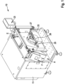
- Fig. 1
- eine schematische Darstellung der erfindungsgemäßen Vorrichtung in einer perspektivischen Ansicht,
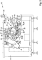
- Fig. 2
- die Darstellung der Vorrichtung gemäß
Figur 1 mit Einblick in die Hohltrommel mit der Kühleinrichtung, - Fig. 3
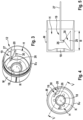
- die Hohltrommel als Einzelteil mit schematisch angedeuteter Kühleinrichtung in perspektivischer Ansicht,
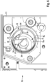
- Fig. 4
- die Hohltrommel in Vorderansicht in die offene Stirnseite hinein,
- Fig. 5
- die Hohltrommel im Schnitt V-V gemäß
Figur 4 , und - Fig. 6
- eine weitere Ausführungsform der Hohltrommel in perspektivischer Ansicht in die offene Stirnseite.
- Die in der Zeichnung dargestellte Vorrichtung dient zum Trennen von Fleisch einerseits und Knochen, Knochenresten, Sehnen, Knorpeln und dergleichen andererseits und weist eine Mehrzahl bevorzugter Merkmale auf. Andere Ausführungsformen, die weniger oder andere Merkmale aufweisen, sind nicht explizit dargestellt. Die Vorrichtung kann in gleicher Weise auch zum Trennen z.B. von Fruchtfleisch von Kernen oder zum Trennen jeglicher anderen vermischten Stoffe unterschiedlicher Fließfähigkeit eingesetzt werden.
- Die dargestellte Vorrichtung 10 ist zum Trennen von miteinander vermischten Stoffen unterschiedlicher Fließfähigkeit ausgebildet und eingerichtet. Die Vorrichtung 10 umfasst ein Rahmengestell 11, eine umlaufend angetriebene und am Rahmengstell 11 gelagerte Hohltrommel 12 mit perforierter Mantelfläche M und mindestens einer mindestens teilweise offenen Stirnseite SV,SH, ein von außen an die Mantelfläche unter Umschlingung eines Teils des Umfangs der Hohltrommel 12 anpressbares, endloses Pressband 13, das umlaufend angetrieben ist, einen durch Pressband 13 und Hohltrommel 12 gebildeten Produkt-Einzugskeil 14 zum Leiten eines aus Pressgut bestehenden Produktstroms zwischen die Hohltrommel 12 und das Pressband 13 in einem Einlaufbereich E des Produktstroms in die Vorrichtung 10, eine Stützvorrichtung 15 für das Pressband 13 mit wenigstens einem Stützelement 16, das auf der der Hohltrommel 12 entgegengesetzten Seite des Pressbandes 13 angeordnet ist, sowie eine Einrichtung 17 zum Abführen von durch die perforierte Mantelfläche M in den Hohlraum H der Hohltrommel 12 gepresstem Separiergut aus der mindestens teilweise offenen Stirnseite SV, SH der Hohltrommel 12.
- Die Einrichtung 17 zum Abführen des Separierguts aus der Hohltrommel 12 kann integraler Bestandteil der Hohltrommel 12 oder als separate Komponente ausgebildet sein. Die zur Vorderseite weisende Stirnseite Sv der Hohltrommel 12 ist offen ausgebildet, die gegenüberliegende Stirnseite SH ist vorzugsweise geschlossen ausgebildet. Die dargestellte Öffnung 18 in der rückseitigen Stirnwand SH dient zur Aufnahme bzw. Lagerung der Hohltrommel 12 auf einer Antriebswelle. Vorderseite und Rückseite können auch vertauscht sein.
- Diese Vorrichtung 10 zeichnet sich erfindungsgemäß dadurch aus, dass der Hohltrommel 12 eine Kühleinrichtung 19 zugeordnet ist, die zum Kühlen des Separierguts während der Verarbeitung mittels eines kryogenen Kühlmediums 20 ausgebildet und eingerichtet ist.
- Das Rahmengestell 11 kann z.B. ein geschlossenes oder mindestens teilweise geschlossenes Gehäuse oder eine Profilkonstruktion oder dergleichen sein. Bevorzugt ist das Gehäuse allseitig im Wesentlichen geschlossen. Am oder im Rahmengestell 11 ist die (nicht dargestellte) Antriebseinheit für die Hohltrommel 12 und/oder das Pressband 13 angeordnet. Die Antriebseinheit kann einen gemeinsamen Antrieb oder separate Antriebsmittel umfassen. Die Rotationsachse R der Hohltrommel 12 verläuft quer zur Förderrichtung F des Produktstroms. In der perforierten Mantelfläche M der Hohltrommel 12 sind (in der Figur nur angedeutete und nicht explizit dargestellte) Bohrungen/Öffnungen ausgebildet, die in unterschiedlichen Mustern angeordnet sein können und den Durchtritt von Teilen des Produktstroms, insbesondere den leichter fließenden, weichen und quetschfähigen Teilen, in das Innere der Hohltrommel 12 erlauben. Die Hohltrommel 12 ist bevorzugt in ihrer gesamten Tiefe bzw. Breite B, die den Arbeitsbereich bildet, mit den Öffnungen versehen. Das Pressband 13 besteht vorzugsweise aus einem elastischen Werkstoff, z.B. Gummi, Polyurethan oder dergleichen und ist um mehrere Umlenkelemente 21 geführt. Vorzugsweise ist ein Umlenkelement 21 als Antriebswalze 22 ausgebildet und eingerichtet. Besonders bevorzugt ist das Umlenkelement 21, das in Förderrichtung F hinter der Hohltrommel 12 platziert ist, die Antriebswalze 22, um das Pressband 13 und damit den Produktstrom ziehend an der Hohltrommel 12 vorbeizuführen. Besonders bevorzugt ist die Antriebswalze 22 gleichzeitig als Andruckwalze und/oder Spannwalze für das Pressband 13 ausgebildet und eingerichtet. Dazu ist die Antriebswalze 22 verstellbar ausgebildet. Durch den eigenen Antrieb der Hohltrommel 12 kann das Fördern des Produktstroms in Förderrichtung F noch unterstützt werden.
- Optional können im Einlaufbereich E, also oberhalb des Produkt-Einzugskeils 14, und/oder im Auslaufbereich A, also in Förderrichtung F hinter der Hohltrommel 12, die auch als Lochtrommel bezeichnet wird, Abstreifelemente angeordnet sein. Diese Abstreifelemente können starr, also mit einem festen Abstand zur Hohltrommel 12 bzw. genauer zur Mantelfläche M, oder variabel steuerbar, also im Abstand zur Hohltrommel 12 bzw. genauer zur Mantelfläche M veränderlich, ausgebildet sein. Die Hohltrommel 12 und das Pressband 13 können mit gleicher Geschwindigkeit angetrieben werden. Optional können die Hohltrommel 12 und das Pressband 13 jedoch auch mit unterschiedlichen Geschwindigkeiten angetrieben werden. Die Geschwindigkeitsdifferenz ist mittels einer Steuer- und/oder Regelungseinrichtung 23 steuerbar und/oder regelbar. Die Stützvorrichtung 15 kann eine Stützkette oder ein Stützband sein. In der dargestellten Ausführung ist die Stützvorrichtung 15 als Rollenbahn 24 ausgebildet, die mehrere Rollen 25 umfasst, die in Förderrichtung F des Produktstroms hintereinander angeordnet und mindestens teilweise federnd gelagert sind.
- Erfindungsgemäß ist die Kühleinrichtung 19 im Hohlraum H der Hohltrommel 12 angeordnet und umfasst mindestens eine Düse 26, die über eine Zuführleitung 27 mit einem (nicht explizit dargestellten) Reservoir an Kühlmedium 20 in Verbindung steht. Die Zuführleitung 27 ist aus der offenen Stirnseite Sv der Hohltrommel 12 herausgeführt. In der
Figur 1 ist erkennbar, dass vor der offenen Stirnseite Sv eine Traverse 28 angeordnet ist, die lösbar am Rahmengestell 11 befestigt ist. An der Traverse 28 ist die Zuführleitung 27 abgestützt, und zwar wahlweise direkt oder, wie dargestellt, indirekt über eine Art Spritzschutzwand 29, die die offene Stirnseite Sv mindestens teilweise abdeckt. In der Zeichnung ist nur eine einzelne Düse 26 dargestellt. Optional sind aber auch mehrere Düsen 26 einsetzbar. Andere Möglichkeiten der Befestigung, des Abstützens oder des Aufliegens der Düse 26 und/oder der Zuführleitung 27 sind ebenfalls möglich. - Die oder jede Düse 26 ist auf den Bereich der Innenfläche der Hohltrommel 12 gerichtet, der etwa dem Bereich des Produkt-Einzugskeils 14 und/oder dem sich daran anschließenden Pressbereich P gegenüberliegt. Beispielsweise kann eine Düse 26 oder Düsenleiste auf den Bereich des Produkt-Einzugskeils 14 gerichtet sein - wie dargestellt -, während eine zweite Düse 26 oder Düsenleiste - nicht dargestellt - auf den Pressbereich P gerichtet ist. Die Position und/oder Ausrichtung jeder Düse 26 ist jedoch variabel und veränderbar. Vorzugsweise ist die oder jede Düse 26 als Flachstrahldüse ausgebildet, die eine Düsenöffnung zur Bildung eines Sprühfächers 30 aufweist, derart, dass das aus der Düse 26 austretende Kühlmedium 20 eine linienförmige und sich über die gesamte Tiefe/Breite B der Hohltrommel 12 erstreckende Beaufschlagung des durch die Mantelfläche M gepressten Separierguts gewährleistet. Anders ausgedrückt deckt der Sprühfächer 30 vorzugsweise die gesamte Arbeitsbreite der Hohltrommel 12 ab. Andere Bauarten der Düsen 26 mit unterschiedlichen Düsenöffnungen sind aber ebenfalls einsetzbar.
- Die oder jede Düse 26 kann frei im Hohlraum H angeordnet sein. Bevorzugt ist der oder jeder Düse 26 eine Abdeckung 31 zugeordnet, die die oder jede Düse 26 mindestens teilweise abdeckt. Die Abdeckung 31 ist dachförmig ausgebildet und vorzugsweise ebenfalls an der Traverse 28 angeordnet. Unterhalb der nach oben geschlossenen und nach unten offenen Abdeckung 31 ist die oder jede Düse 26 angeordnet, so dass der Sprühfächer 30 hindernisfrei gebildet werden kann.
- Optional kann die Vorrichtung 10 eine (nicht explizit dargestellte) Einrichtung zum Sammeln und Abführen des in den Hohlraum H der Hohltrommel 12 geleiteten Kühlmediums 20 umfassen, die der Kühlreinrichtung 19 zugeordnet ist. Die Einrichtung zum Sammeln des Kühlmediums 20 kann mindestens eine Abdeckhaube und einen über Abluftleitungen mit der Abdeckhaube verbundenen Abluftventilator umfassen. Die Abdeckhaube kann z.B. den gesamten Bereich der offenen Stirnseite Sv der Hohltrommel 12 umschließen im Sinne von abdecken, so dass ein Absaugen des verbrauchten, mindestens überwiegend gasförmigen Kühlmediums 20 sichergestellt ist. Andere Konstruktionen zum Absaugen des verbrauchten Kühlmediums 20 aus dem Hohlraum H der Hohltrommel 12 sind ebenfalls einsetzbar.
- Die oder jede Zuführleitung 27 zum Zuführen des kryogenes Kühlmediums 20 zu der oder jeder Düse 26 umfasst eine Mess- und/oder Regelungstrecke, die Bestandteil der Vorrichtung 10 oder einer übergeordneten Einheit sein kann. Als kryogenes Kühlmedium 20 wird besonders bevorzugt flüssiger Stickstoff (LN2) eingesetzt. In anderen Ausführungen kann z.B. auch flüssiges Kohlendioxid (LCO2) als kryogenes Kühlmedium 20 eingesetzt werden. Die Kühlmedien können auch in Gasform eingesetzt werden.
- Das durch die Mantelfläche M gepresste Separiergut kann von alleine, alleine durch die Rotation der Hohltrommel 12, aus dieser abgeführt werden. Dann bildet die Hohltrommel 12 selbst die Einrichtung 17 zum Abführen des Separierguts. Vorzugsweise umfasst die Einrichtung 17 zum Abführen des Separierguts ein Abstreifelement 32 und/oder eine Auswurfschnecke. In der Zeichnung ist das bevorzugte Abstreifelement 32 dargestellt, das ebenfalls lösbar an der Traverse 28 befestigt sein kann. Das Abstreifelement 32 umfasst eine Produktabstreifkante 33 und eine Produktleitfläche 34, wobei die Produktleitfläche 34 derart geformt und/oder ausgerichtet ist, dass das von der Innenfläche der Hohltrommel 12 mittels der Produktabstreifkante 33 abgestreifte Separiergut in Richtung der offenen Stirnseite Sv der Hohltrommel 12 geleitet wird. Andere Ausbildungen des vorzugsweise einstückig ausgebildeten Abstreifelementes 32 und andere Konstruktionen zum Abführen des Separierguts aus dem Hohlraum H der Hohltrommel 12 sind ebenfalls einsetzbar. Das abgeführte Separiergut kann z.B. auf eine Abführrinne 35 oder dergleichen fallen, die optional gekühlt sein kann und dazu mit einer entsprechenden Einrichtung verbunden ist.
- Im Folgenden wird das Verfahren anhand der Zeichnung näher beschrieben. Das Verfahren dient und ist entsprechend zum Trennen von miteinander vermischten Stoffen unterschiedlicher Fließfähigkeit ausgebildet und eingerichtet. Zunächst wird ein aus Pressgut bestehender Produktstrom in einen Produkt-Einzugskeil 14, der durch eine Hohltrommel 12 mit perforierter Mantelfläche M und ein Pressband 13, das von außen an der Hohltrommel 12 unter Umschlingung eines Teils des Umfangs anliegt, gebildet ist, zugeführt. Für den Trennprozess werden die Hohltrommel 12 und das Pressband 13 zum Einziehen des Produktstroms zwischen die Hohltrommel 12 und das Pressband 13 umlaufend angetrieben. Bevorzugt ist die Hohltrommel 12 (in der Ansicht gemäß
Figur 1 ) im Uhrzeigersinn angetrieben, während die Antriebswalze 22 für das Pressband (in der Ansicht gemäß derFiguren 1 und2 ) entgegen dem Uhrzeigersinn angetrieben ist, so dass die Hohltrommel 12 und das Pressband 13 im Bereich der Umschlingung, also im Pressbereich P, die gleiche Förderrichtung F aufweisen, wobei die Geschwindigkeiten gleich sein oder voneinander abweichen können. Durch den Transport des Produktstroms durch den Pressbereich P werden die leichter fließenden Bestandteile des Produktstroms mittels des Pressbandes 13 als Separiergut durch die Perforation der Mantelfläche M der Hohltrommel 12 in den inneren Hohlraum H der Hohltrommel 12 gepresst und aus einer mindestens teilweise offenen Stirnseite SV und/oder SH der Hohltrommel 12 abgeführt, während die schwerer fließenden Bestandteile des Produktstroms außen auf der Mantelfläche M der Hohltrommel 12 verbleiben und separat abgegeben werden. - Vorzugsweise wird das Pressband 13 während des Trennens des Produktstroms in seine Bestandteile auf der der Hohltrommel 12 entgegengesetzten Seite des Pressbandes 13 durch eine mindestens ein Stützelement 16 umfassende Stützvorrichtung 15 gestützt.
- Dieses Verfahren zeichnet sich erfindungsgemäß dadurch aus, dass das durch die perforierte Mantelfläche M in den Hohlraum H der Hohltrommel 12 gepresste Separiergut mittels eines kryogenen Kühlmediums 20 in der Hohltrommel 12 gekühlt wird, wobei das Separiergut direkt und unmittelbar während des Trennprozesses, also beim Pressen durch die Mantelfläche M und/oder beim Abführen aus der Hohltrommel 12, mit dem kryogenen Kühlmedium 20 beaufschlagt wird. Das Kühlmedium 20 wird dazu linienförmig, fächerförmig oder andersförmig über die gesamte Breite B (entsprechend der Arbeitstiefe/-breite) der Hohltrommel 12 - parallel ausgerichtet zur Rotationsachse R der Hohltrommel 12 - auf das durch den Trennprozess zerkleinerte und in der Oberfläche vergrößerte Separiergut aufgebracht. Zur Kühlung des Separierguts wird dieses bevorzugt wahlweise mit flüssigem Stickstoff (LN2) als flüssigem, kryogenem Kühlmedium 20 oder mit flüssigem Kohlendioxid (LCO2) als flüssigem, kryogenem Kühlmedium beaufschlagt. Andere flüssige oder gasförmige kryogene Kühlmedien 20 können aber ebenfalls eingesetzt und verwendet werden.
- Grundsätzlich kann das unverbrauchte Kühlmedium 20 in Gasform und/oder in flüssiger Form, also z.B. als Aerosol, Dampf, Nebel, Rauch oder dergleichen abhängig vom jeweiligen Kühlmedium 20 in die Umgebung entweichen. Vorzugsweise wird das in den Hohlraum H der Hohltrommel 12 geleitete Kühlmedium 20 gesammelt und abgeführt. Das kann z.B. ein Absaugen sein. Das gekühlte Separiergut kann z.B. durch die Rotation der Hohltrommel 12 aus der offenen Stirnseite Sv der Hohltrommel 12 fallen. Bevorzugt wird das gekühlte Separiergut jedoch von der Innenfläche der Hohltrommel 12 abgestreift und aus der Hohltrommel 12 abgeführt.
- Besonders bevorzugt wird die Wunschtemperatur des Separierguts über das Zuführen des Kühlmediums auf das Separiergut gesteuert. Dazu kann die Mess- und/oder Regelungsstrecke innerhalb der Zuführleitung 27 dienen und eingesetzt werden. Mittels der Mess- und/oder Regelungsstrecke können u.a. z.B. Zuflussmenge, Temperatur, Zuflussgeschwindigkeit etc. des Kühlmediums überwacht und geregelt werden, um einen optimalen Kühlungseffekt zu erreichen. Mit anderen Worten lässt sich eine Wunschtemperatur für eine optimale Prozesskontrolle und Produktqualität einstellen.
- Ganz besonders bevorzugt wird das Verfahren mit einer Vorrichtung 10 nach einem oder mehreren der Ansprüche 1 bis 11 ausgeführt.
Claims (19)
- Vorrichtung (10), ausgebildet und eingerichtet zum Trennen von miteinander vermischten Stoffen unterschiedlicher Fließfähigkeit, umfassend ein Rahmengestell (11), eine umlaufend angetriebene und am Rahmengstell (11) gelagerte Hohltrommel (12) mit perforierter Mantelfläche (M) und mindestens einer mindestens teilweise offenen Stirnseite (SV, SH), ein von außen an die Mantelfläche unter Umschlingung eines Teils des Umfangs der Hohltrommel (12) anpressbares, endloses Pressband (13), das umlaufend angetrieben ist, einen durch Pressband (13) und Hohltrommel (12) gebildeten Produkt-Einzugskeil (14) zum Leiten eines aus Pressgut bestehenden Produktstroms zwischen die Hohltrommel (12) und das Pressband (13) in einem Einlaufbereich (E) des Produktstroms in die Vorrichtung (10), eine Stützvorrichtung (15) für das Pressband (13) mit wenigstens einem Stützelement (16), das auf der der Hohltrommel (12) entgegengesetzten Seite des Pressbandes (13) angeordnet ist, sowie eine Einrichtung (17) zum Abführen von durch die perforierte Mantelfläche (M) in den Hohlraum (H) der Hohltrommel (12) gepresstem Separiergut aus der mindestens teilweise offenen Stirnseite (SV, SH) der Hohltrommel (12), dadurch gekennzeichnet, dass der Hohltrommel (12) eine Kühleinrichtung (19) zugeordnet ist, die zum Kühlen des Separierguts während der Verarbeitung mittels eines kryogenen Kühlmediums (20) ausgebildet und eingerichtet ist, wobei die Kühleinrichtung (19) im Hohlraum (H) der Hohltrommel (12) angeordnet ist und mindestens eine Düse (26) umfasst, die über eine Zuführleitung (27) mit einem Reservoir an Kühlmedium (20) in Verbindung steht.
- Vorrichtung (10) nach Anspruch 1, dadurch gekennzeichnet, dass die oder jede Düse (26) mindestens auf den Bereich der Innenfläche der Hohltrommel (12) gerichtet ist, der etwa dem Bereich des Produkt-Einzugskeils (14) und/oder dem sich daran anschließenden Pressbereich (P) gegenüberliegt.
- Vorrichtung (10) nach Anspruch 1 oder 2, dadurch gekennzeichnet, dass die oder jede Düse (26) als Flachstrahldüse ausgebildet ist, die eine Düsenöffnung zur Bildung eines Sprühfächers (27) aufweist, derart, dass das aus der Düse austretende Kühlmedium (20) eine linienförmige und sich über die gesamte Breite (B) der Hohltrommel (12) erstreckende Beaufschlagung des durch die Mantelfläche (M) gepressten Separierguts gewährleistet.
- Vorrichtung (10) nach einem oder mehreren der Ansprüche 1 bis 3, dadurch gekennzeichnet, dass der oder jeder Düse (26) eine Abdeckung (31) zugeordnet ist, die die oder jede Düse (26) mindestens teilweise abdeckt.
- Vorrichtung (10) nach einem oder mehreren der Ansprüche 1 bis 4, dadurch gekennzeichnet, dass der Kühlreinrichtung (17) eine Einrichtung zum Sammeln und Abführen des in den Hohlraum (H) der Hohltrommel (12) geleiteten Kühlmediums (20) zugeordnet ist.
- Vorrichtung (10) nach Anspruch 5, dadurch gekennzeichnet, dass die Einrichtung zum Sammeln des Kühlmediums mindestens eine Abdeckhaube und einen über Abluftleitungen mit der Abdeckhaube verbundenen Abluftventilator umfasst.
- Vorrichtung (10) nach einem oder mehreren der Ansprüche 1 bis 6, dadurch gekennzeichnet, dass die oder jede Zuführleitung (27) zum Zuführen des kryogenes Kühlmediums (20) zu der oder jeder Düse (26) eine Mess- und/oder Regelungstrecke umfasst.
- Vorrichtung (10) nach einem oder mehreren der Ansprüche 1 bis 7, dadurch gekennzeichnet, dass das kryogene Kühlmedium (20) flüssiger Stickstoff (LIN bzw. LN2) ist.
- Vorrichtung (10) nach einem oder mehreren der Ansprüche 1 bis 7, dadurch gekennzeichnet, dass das kryogene Kühlmedium (20) flüssiges Kohlendioxid (LIC bzw. LCO2) ist.
- Vorrichtung (10) nach einem oder mehreren der Ansprüche 1 bis 9, dadurch gekennzeichnet, dass die Einrichtung (17) zum Abführen des Separierguts ein Abstreifelement (32) und/oder eine Auswurfschnecke umfasst.
- Vorrichtung (10) nach Anspruch 10, dadurch gekennzeichnet, dass das Abstreifelement (12) eine Produktabstreifkante (33) und eine Produktleitfläche (34) umfasst, wobei die Produktleitfläche (34) derart geformt und/oder ausgerichtet ist, dass das von der Innenfläche der Hohltrommel (12) mittels der Produktabstreifkante (33) abgestreifte Separiergut in Richtung der offenen Stirnseite (Sv) der Hohltrommel (12) geleitet wird.
- Verfahren zum Trennen von miteinander vermischten Stoffen unterschiedlicher Fließfähigkeit, umfassend die Schritte:- Zuführen eines aus Pressgut bestehenden Produktstroms in einen Produkt-Einzugskeil (14), der durch eine Hohltrommel (12) mit perforierter Mantelfläche (M) und ein Pressband (13), das von außen an der Hohltrommel (12) unter Umschlingung eines Teils des Umfangs anliegt, gebildet ist,- umlaufendes Antreiben der Hohltrommel (12) und/oder des Pressbandes (13) zum Einziehen des Produktstroms zwischen die Hohltrommel (12) und das Pressband (13),- wobei die leichter fließenden Bestandteile des Produktstroms mittels des Pressbandes (13) als Separiergut durch die Perforation der Mantelfläche (M) der Hohltrommel (12) in den Hohlraum (H) der Hohltrommel (12) gepresst und aus einer mindestens teilweise offenen Stirnseite (SV, SH) der Hohltrommel (12) abgeführt werden, während die schwerer fließenden Bestandteile des Produktstroms außen auf der Mantelfläche (M) der Hohltrommel (12) verbleiben und separat abgegeben werden,dadurch gekennzeichnet, dass das durch die perforierte Mantelfläche (M) in den Hohlraum (H) der Hohltrommel (12) gepresste Separiergut mittels eines kryogenen Kühlmediums (20) in der Hohltrommel (12) gekühlt wird, wobei das Separiergut direkt und unmittelbar während des Trennprozesses, also beim Pressen durch die Mantelfläche (M) und/oder beim Abführen aus der Hohltrommel (12), mit dem kryogenen Kühlmedium (20) beaufschlagt wird.
- Verfahren nach Anspruch 12, dadurch gekennzeichnet, dass das Kühlmedium (20) linienförmig über die gesamte Breite (B) der Hohltrommel (12) auf das durch den Trennprozess zerkleinerte Separiergut aufgebracht wird.
- Verfahren nach Anspruch 12 oder 13, dadurch gekennzeichnet, dass das Separiergut mit flüssigem Stickstoff (LIN bzw. LN2) als kryogenem Kühlmedium (20) beaufschlagt wird.
- Verfahren nach einem oder mehreren der Ansprüche 12 bis 14, dadurch gekennzeichnet, dass das Separiergut mit flüssigem Kohlendioxid (LIC bzw. LCO2) als kryogenem Kühlmedium (20) beaufschlagt wird.
- Verfahren nach einem oder mehreren der Ansprüche 12 bis 15, dadurch gekennzeichnet, dass über das Zuführen des Kühlmediums auf das Separiergut die Wunschtemperatur desselben gesteuert wird.
- Verfahren nach einem oder mehreren der Ansprüche 12 bis 16, dadurch gekennzeichnet, dass das in den Hohlraum (H) der Hohltrommel (12) geleitete Kühlmedium (20) gesammelt und abgeführt wird.
- Verfahren nach einem oder mehreren der Ansprüche 12 bis 17, dadurch gekennzeichnet, dass das gekühlte Separiergut von der Innenfläche der Hohltrommel (12) abgestreift und aus der Hohltrommel (12) abgeführt wird.
- Verfahren nach einem oder mehreren der Ansprüche 12 bis 18, dadurch gekennzeichnet, dass es mit einer Vorrichtung (10) nach einem oder mehreren der Ansprüche 1 bis 11 ausgeführt wird.
Applications Claiming Priority (2)
| Application Number | Priority Date | Filing Date | Title |
|---|---|---|---|
| DE102020118720.3A DE102020118720A1 (de) | 2020-07-15 | 2020-07-15 | Vorrichtung und Verfahren zum Trennen von miteinander vermischten Stoffen unterschiedlicher Fließfähigkeit |
| PCT/EP2021/069645 WO2022013305A1 (de) | 2020-07-15 | 2021-07-14 | Vorrichtung und verfahren zum trennen von miteinander vermischten stoffen unterschiedlicher fliessfähigkeit |
Publications (2)
| Publication Number | Publication Date |
|---|---|
| EP4182159A1 EP4182159A1 (de) | 2023-05-24 |
| EP4182159B1 true EP4182159B1 (de) | 2024-08-28 |
Family
ID=77050990
Family Applications (1)
| Application Number | Title | Priority Date | Filing Date |
|---|---|---|---|
| EP21745954.4A Active EP4182159B1 (de) | 2020-07-15 | 2021-07-14 | Vorrichtung und verfahren zum trennen von miteinander vermischten stoffen unterschiedlicher fliessfähigkeit |
Country Status (12)
| Country | Link |
|---|---|
| US (1) | US12168333B2 (de) |
| EP (1) | EP4182159B1 (de) |
| CN (1) | CN115812030B (de) |
| AU (1) | AU2021310432B2 (de) |
| BR (1) | BR112023000693A2 (de) |
| CA (1) | CA3182787A1 (de) |
| DE (1) | DE102020118720A1 (de) |
| DK (1) | DK4182159T3 (de) |
| ES (1) | ES2990245T3 (de) |
| MX (1) | MX2023000680A (de) |
| PL (1) | PL4182159T3 (de) |
| WO (1) | WO2022013305A1 (de) |
Family Cites Families (20)
| Publication number | Priority date | Publication date | Assignee | Title |
|---|---|---|---|---|
| US3368363A (en) | 1966-05-31 | 1968-02-13 | Du Pont | Process for freezing food using liquid refrigerant |
| US4018389A (en) | 1975-09-29 | 1977-04-19 | Paoli Stephen A | High production mechanical separator machine |
| US4156384A (en) | 1976-08-30 | 1979-05-29 | Stoelting, Inc. | Method and apparatus for separating liquids from soft particulate food solids |
| JPS60237934A (ja) | 1984-05-12 | 1985-11-26 | 東洋水産機械株式会社 | 魚肉採取機 |
| DE3615406A1 (de) | 1986-05-07 | 1987-11-12 | Linde Ag | Vorrichtung zur herstellung von tiefgefrorenem granulat |
| US4889048A (en) * | 1988-04-13 | 1989-12-26 | Miller Ray R | High heat flux roll and press utilizing same |
| DE4116476C2 (de) | 1991-05-21 | 1994-09-22 | Nordischer Maschinenbau | Separiereinrichtung |
| DE4319062A1 (de) * | 1993-06-09 | 1994-12-22 | Kraftanlagen Ag Heidelberg | Verfahren und Vorrichtung zur Herstellung von Bahnen aus thermoplastischen Kunststoff-Mischungen, Harzgemischen o. dgl. mittels Bandpressen |
| DE4328627C2 (de) | 1993-08-27 | 1995-10-05 | Nordischer Maschinenbau | Separator zum Gewinnen des Restfleisches von Knochensträngen |
| DE4411502A1 (de) * | 1994-04-06 | 1995-10-12 | Alexander Seitz | Verfahren und Vorrichtung zum Ablösen von Fleisch |
| JP3935143B2 (ja) | 2003-12-08 | 2007-06-20 | 月島機械株式会社 | ベルトプレス型脱水機の洗浄方法 |
| AP3397A (en) * | 2009-04-01 | 2015-08-31 | Freddy Hirsch Group Propiertary Ltd | A system, method and apparatus for processing foodproducts |
| DE202010011056U1 (de) | 2010-08-04 | 2011-11-07 | Modernpack Hoppe Gmbh | Trennmaschine |
| GB201405975D0 (en) * | 2014-04-02 | 2014-05-14 | Univ Ulster | A method and apparatus for pressing oilseed to extract oil therefrom |
| DE102016108200B3 (de) | 2016-05-03 | 2016-12-15 | Nordischer Maschinenbau Rud. Baader Gmbh + Co. Kg | Separator zum Trennen von miteinander vermischten Stoffen unterschiedlicher Fließfähigkeit |
| US11173426B2 (en) * | 2017-12-22 | 2021-11-16 | Sustainable Energy Solutions, Inc. | Method for solid-liquid separations |
| DE102018101985B3 (de) * | 2018-01-30 | 2018-09-27 | Modernpack Hoppe Gmbh | Weichseparator mit füllzustandsabhängiger Anpassung der Geschwindigkeit und Verfahren zum Betreiben eines solchen Weichseparators |
| DE102019116720B3 (de) * | 2019-06-20 | 2020-06-10 | Nordischer Maschinenbau Rud. Baader Gmbh + Co. Kg | Vorrichtung und Verfahren zum Trennen von miteinander vermischten Stoffen unterschiedlicher Fließfähigkeit |
| US11832623B2 (en) * | 2019-11-08 | 2023-12-05 | Provisur Technologies, Inc. | Separating machine with feeding wheel |
| EP3939777B1 (de) * | 2020-07-15 | 2025-04-02 | Nordischer Maschinenbau Rud. Baader Gmbh + Co Kg | Vorrichtung zum trennen von miteinander vermischten Stoffen unterschiedlicher Fliessfähigkeit |
-
2020
- 2020-07-15 DE DE102020118720.3A patent/DE102020118720A1/de active Pending
-
2021
- 2021-07-14 PL PL21745954.4T patent/PL4182159T3/pl unknown
- 2021-07-14 MX MX2023000680A patent/MX2023000680A/es unknown
- 2021-07-14 CA CA3182787A patent/CA3182787A1/en active Pending
- 2021-07-14 BR BR112023000693A patent/BR112023000693A2/pt unknown
- 2021-07-14 ES ES21745954T patent/ES2990245T3/es active Active
- 2021-07-14 EP EP21745954.4A patent/EP4182159B1/de active Active
- 2021-07-14 WO PCT/EP2021/069645 patent/WO2022013305A1/de not_active Ceased
- 2021-07-14 US US18/016,529 patent/US12168333B2/en active Active
- 2021-07-14 DK DK21745954.4T patent/DK4182159T3/da active
- 2021-07-14 AU AU2021310432A patent/AU2021310432B2/en active Active
- 2021-07-14 CN CN202180047827.6A patent/CN115812030B/zh active Active
Also Published As
| Publication number | Publication date |
|---|---|
| CN115812030A (zh) | 2023-03-17 |
| DK4182159T3 (da) | 2024-11-25 |
| DE102020118720A1 (de) | 2022-01-20 |
| EP4182159A1 (de) | 2023-05-24 |
| US20230286241A1 (en) | 2023-09-14 |
| WO2022013305A8 (de) | 2022-09-22 |
| PL4182159T3 (pl) | 2025-02-03 |
| BR112023000693A2 (pt) | 2023-04-25 |
| US12168333B2 (en) | 2024-12-17 |
| CN115812030B (zh) | 2025-03-11 |
| CA3182787A1 (en) | 2022-01-20 |
| ES2990245T3 (es) | 2024-11-29 |
| AU2021310432A1 (en) | 2023-02-16 |
| MX2023000680A (es) | 2023-03-13 |
| WO2022013305A1 (de) | 2022-01-20 |
| AU2021310432B2 (en) | 2024-08-29 |
Similar Documents
| Publication | Publication Date | Title |
|---|---|---|
| DE112011100359B4 (de) | Vorrichtung zum Trennen von miteinander vermischten Stoffen unterschiedlicher Fließfähigkeit | |
| DE3020351C2 (de) | ||
| DE102017001784B4 (de) | Conchiervorrichtung und Verfahren zum Conchieren einer Produktmasse | |
| WO2002091842A1 (de) | Vorrichtung zum abschwarten und enthäuten von behandlungsgut | |
| DE102007063465B4 (de) | Vorrichtung und Verfahren zum Trennen von miteinander vermischten Stoffen unterschiedlicher Fließfähigkeit | |
| EP0640290B1 (de) | Separator zum Gewinnen des Restfleisches von Knochensträngen | |
| EP3962722B1 (de) | Vorrichtung und Verfahren zum trennen von miteinander vermischten Stoffen unterschiedlicher Fliessfähigkeit | |
| EP3939777B1 (de) | Vorrichtung zum trennen von miteinander vermischten Stoffen unterschiedlicher Fliessfähigkeit | |
| EP3894203B1 (de) | Vorrichtung und verfahren zum trennen von miteinander vermischten stoffen unterschiedlicher fliessfähigkeit | |
| DE4446323A1 (de) | Tabakrecycling | |
| DE102018102672B3 (de) | Vorrichtung zum Trennen von miteinander vermischten Stoffen unterschiedlicher Fließfähigkeit | |
| EP4182159A1 (de) | Vorrichtung und verfahren zum trennen von miteinander vermischten stoffen unterschiedlicher fliessfähigkeit | |
| EP3569397A1 (de) | Vorrichtung und verfahren zum trennen von miteinander vermischten stoffen unterschiedlicher fliessfähigkeit | |
| EP4182158A1 (de) | Vorrichtung und verfahren zum trennen von miteinander vermischten stoffen unterschiedlicher fliessfähigkeit | |
| EP0658311B1 (de) | Vorrichtung zum Entfernen der Haut von den Körpern geschlachteten Geflügels | |
| DE4207730C2 (de) | Gezogenes oder selbstfahrendes Ernte- und Verarbeitungsfahrzeug | |
| EP0519309A2 (de) | Pressvorrichtung zum Flüssigkeitsentzug aus einem Gut | |
| DE1507991C3 (de) | Vorrichtung zum Trennen des Fleisches von harten Gewebeteilen | |
| EP1910753A1 (de) | Vorrichtung und verfahren zur oberflächenkühlung von gegenständen | |
| DE7438492U (de) | Vorrichtung zum spalten entkernen und entstielen von schoten und fruechten | |
| WO2023083469A1 (de) | Messeraggregat sowie vorrichtung und verfahren zum verarbeiten von tierischen produkten | |
| DE1582628A1 (de) | Verfahren und Vorrichtung zur Trennung von Feststoffen und von diesen befreiten Artikeln | |
| DE29622810U1 (de) | Einrichtung zum Gewinnen von Fischfleisch in musartiger Konsistenz |
Legal Events
| Date | Code | Title | Description |
|---|---|---|---|
| STAA | Information on the status of an ep patent application or granted ep patent |
Free format text: STATUS: UNKNOWN |
|
| STAA | Information on the status of an ep patent application or granted ep patent |
Free format text: STATUS: THE INTERNATIONAL PUBLICATION HAS BEEN MADE |
|
| PUAI | Public reference made under article 153(3) epc to a published international application that has entered the european phase |
Free format text: ORIGINAL CODE: 0009012 |
|
| STAA | Information on the status of an ep patent application or granted ep patent |
Free format text: STATUS: REQUEST FOR EXAMINATION WAS MADE |
|
| 17P | Request for examination filed |
Effective date: 20230109 |
|
| AK | Designated contracting states |
Kind code of ref document: A1 Designated state(s): AL AT BE BG CH CY CZ DE DK EE ES FI FR GB GR HR HU IE IS IT LI LT LU LV MC MK MT NL NO PL PT RO RS SE SI SK SM TR |
|
| DAV | Request for validation of the european patent (deleted) | ||
| DAX | Request for extension of the european patent (deleted) | ||
| GRAP | Despatch of communication of intention to grant a patent |
Free format text: ORIGINAL CODE: EPIDOSNIGR1 |
|
| STAA | Information on the status of an ep patent application or granted ep patent |
Free format text: STATUS: GRANT OF PATENT IS INTENDED |
|
| INTG | Intention to grant announced |
Effective date: 20240209 |
|
| GRAS | Grant fee paid |
Free format text: ORIGINAL CODE: EPIDOSNIGR3 |
|
| GRAA | (expected) grant |
Free format text: ORIGINAL CODE: 0009210 |
|
| STAA | Information on the status of an ep patent application or granted ep patent |
Free format text: STATUS: THE PATENT HAS BEEN GRANTED |
|
| P01 | Opt-out of the competence of the unified patent court (upc) registered |
Free format text: CASE NUMBER: APP_39895/2024 Effective date: 20240704 |
|
| AK | Designated contracting states |
Kind code of ref document: B1 Designated state(s): AL AT BE BG CH CY CZ DE DK EE ES FI FR GB GR HR HU IE IS IT LI LT LU LV MC MK MT NL NO PL PT RO RS SE SI SK SM TR |
|
| REG | Reference to a national code |
Ref country code: CH Ref legal event code: EP |
|
| REG | Reference to a national code |
Ref country code: DE Ref legal event code: R096 Ref document number: 502021004971 Country of ref document: DE |
|
| REG | Reference to a national code |
Ref country code: IE Ref legal event code: FG4D Free format text: LANGUAGE OF EP DOCUMENT: GERMAN |
|
| REG | Reference to a national code |
Ref country code: NL Ref legal event code: FP |
|
| REG | Reference to a national code |
Ref country code: DK Ref legal event code: T3 Effective date: 20241119 |
|
| REG | Reference to a national code |
Ref country code: ES Ref legal event code: FG2A Ref document number: 2990245 Country of ref document: ES Kind code of ref document: T3 Effective date: 20241129 |
|
| REG | Reference to a national code |
Ref country code: LT Ref legal event code: MG9D |
|
| PG25 | Lapsed in a contracting state [announced via postgrant information from national office to epo] |
Ref country code: GR Free format text: LAPSE BECAUSE OF FAILURE TO SUBMIT A TRANSLATION OF THE DESCRIPTION OR TO PAY THE FEE WITHIN THE PRESCRIBED TIME-LIMIT Effective date: 20241129 Ref country code: FI Free format text: LAPSE BECAUSE OF FAILURE TO SUBMIT A TRANSLATION OF THE DESCRIPTION OR TO PAY THE FEE WITHIN THE PRESCRIBED TIME-LIMIT Effective date: 20240828 Ref country code: PT Free format text: LAPSE BECAUSE OF FAILURE TO SUBMIT A TRANSLATION OF THE DESCRIPTION OR TO PAY THE FEE WITHIN THE PRESCRIBED TIME-LIMIT Effective date: 20241230 |
|
| PG25 | Lapsed in a contracting state [announced via postgrant information from national office to epo] |
Ref country code: BG Free format text: LAPSE BECAUSE OF FAILURE TO SUBMIT A TRANSLATION OF THE DESCRIPTION OR TO PAY THE FEE WITHIN THE PRESCRIBED TIME-LIMIT Effective date: 20240828 |
|
| PG25 | Lapsed in a contracting state [announced via postgrant information from national office to epo] |
Ref country code: LV Free format text: LAPSE BECAUSE OF FAILURE TO SUBMIT A TRANSLATION OF THE DESCRIPTION OR TO PAY THE FEE WITHIN THE PRESCRIBED TIME-LIMIT Effective date: 20240828 |
|
| PG25 | Lapsed in a contracting state [announced via postgrant information from national office to epo] |
Ref country code: HR Free format text: LAPSE BECAUSE OF FAILURE TO SUBMIT A TRANSLATION OF THE DESCRIPTION OR TO PAY THE FEE WITHIN THE PRESCRIBED TIME-LIMIT Effective date: 20240828 |
|
| PG25 | Lapsed in a contracting state [announced via postgrant information from national office to epo] |
Ref country code: RS Free format text: LAPSE BECAUSE OF FAILURE TO SUBMIT A TRANSLATION OF THE DESCRIPTION OR TO PAY THE FEE WITHIN THE PRESCRIBED TIME-LIMIT Effective date: 20241128 |
|
| PG25 | Lapsed in a contracting state [announced via postgrant information from national office to epo] |
Ref country code: RS Free format text: LAPSE BECAUSE OF FAILURE TO SUBMIT A TRANSLATION OF THE DESCRIPTION OR TO PAY THE FEE WITHIN THE PRESCRIBED TIME-LIMIT Effective date: 20241128 Ref country code: PT Free format text: LAPSE BECAUSE OF FAILURE TO SUBMIT A TRANSLATION OF THE DESCRIPTION OR TO PAY THE FEE WITHIN THE PRESCRIBED TIME-LIMIT Effective date: 20241230 Ref country code: LV Free format text: LAPSE BECAUSE OF FAILURE TO SUBMIT A TRANSLATION OF THE DESCRIPTION OR TO PAY THE FEE WITHIN THE PRESCRIBED TIME-LIMIT Effective date: 20240828 Ref country code: HR Free format text: LAPSE BECAUSE OF FAILURE TO SUBMIT A TRANSLATION OF THE DESCRIPTION OR TO PAY THE FEE WITHIN THE PRESCRIBED TIME-LIMIT Effective date: 20240828 Ref country code: GR Free format text: LAPSE BECAUSE OF FAILURE TO SUBMIT A TRANSLATION OF THE DESCRIPTION OR TO PAY THE FEE WITHIN THE PRESCRIBED TIME-LIMIT Effective date: 20241129 Ref country code: FI Free format text: LAPSE BECAUSE OF FAILURE TO SUBMIT A TRANSLATION OF THE DESCRIPTION OR TO PAY THE FEE WITHIN THE PRESCRIBED TIME-LIMIT Effective date: 20240828 Ref country code: BG Free format text: LAPSE BECAUSE OF FAILURE TO SUBMIT A TRANSLATION OF THE DESCRIPTION OR TO PAY THE FEE WITHIN THE PRESCRIBED TIME-LIMIT Effective date: 20240828 |
|
| PG25 | Lapsed in a contracting state [announced via postgrant information from national office to epo] |
Ref country code: SM Free format text: LAPSE BECAUSE OF FAILURE TO SUBMIT A TRANSLATION OF THE DESCRIPTION OR TO PAY THE FEE WITHIN THE PRESCRIBED TIME-LIMIT Effective date: 20240828 Ref country code: RO Free format text: LAPSE BECAUSE OF FAILURE TO SUBMIT A TRANSLATION OF THE DESCRIPTION OR TO PAY THE FEE WITHIN THE PRESCRIBED TIME-LIMIT Effective date: 20240828 |
|
| PG25 | Lapsed in a contracting state [announced via postgrant information from national office to epo] |
Ref country code: EE Free format text: LAPSE BECAUSE OF FAILURE TO SUBMIT A TRANSLATION OF THE DESCRIPTION OR TO PAY THE FEE WITHIN THE PRESCRIBED TIME-LIMIT Effective date: 20240828 |
|
| PG25 | Lapsed in a contracting state [announced via postgrant information from national office to epo] |
Ref country code: CZ Free format text: LAPSE BECAUSE OF FAILURE TO SUBMIT A TRANSLATION OF THE DESCRIPTION OR TO PAY THE FEE WITHIN THE PRESCRIBED TIME-LIMIT Effective date: 20240828 |
|
| PG25 | Lapsed in a contracting state [announced via postgrant information from national office to epo] |
Ref country code: SK Free format text: LAPSE BECAUSE OF FAILURE TO SUBMIT A TRANSLATION OF THE DESCRIPTION OR TO PAY THE FEE WITHIN THE PRESCRIBED TIME-LIMIT Effective date: 20240828 |
|
| REG | Reference to a national code |
Ref country code: DE Ref legal event code: R097 Ref document number: 502021004971 Country of ref document: DE |
|
| PLBE | No opposition filed within time limit |
Free format text: ORIGINAL CODE: 0009261 |
|
| STAA | Information on the status of an ep patent application or granted ep patent |
Free format text: STATUS: NO OPPOSITION FILED WITHIN TIME LIMIT |
|
| PGFP | Annual fee paid to national office [announced via postgrant information from national office to epo] |
Ref country code: PL Payment date: 20250603 Year of fee payment: 5 |
|
| PGFP | Annual fee paid to national office [announced via postgrant information from national office to epo] |
Ref country code: IS Payment date: 20250623 Year of fee payment: 5 |
|
| 26N | No opposition filed |
Effective date: 20250530 |
|
| PGFP | Annual fee paid to national office [announced via postgrant information from national office to epo] |
Ref country code: NL Payment date: 20250723 Year of fee payment: 5 |
|
| PG25 | Lapsed in a contracting state [announced via postgrant information from national office to epo] |
Ref country code: SE Free format text: LAPSE BECAUSE OF FAILURE TO SUBMIT A TRANSLATION OF THE DESCRIPTION OR TO PAY THE FEE WITHIN THE PRESCRIBED TIME-LIMIT Effective date: 20240828 |
|
| PGFP | Annual fee paid to national office [announced via postgrant information from national office to epo] |
Ref country code: ES Payment date: 20250819 Year of fee payment: 5 |
|
| PGFP | Annual fee paid to national office [announced via postgrant information from national office to epo] |
Ref country code: DK Payment date: 20250723 Year of fee payment: 5 Ref country code: DE Payment date: 20250722 Year of fee payment: 5 |
|
| PGFP | Annual fee paid to national office [announced via postgrant information from national office to epo] |
Ref country code: NO Payment date: 20250722 Year of fee payment: 5 |
|
| PGFP | Annual fee paid to national office [announced via postgrant information from national office to epo] |
Ref country code: IT Payment date: 20250731 Year of fee payment: 5 |
|
| PGFP | Annual fee paid to national office [announced via postgrant information from national office to epo] |
Ref country code: GB Payment date: 20250724 Year of fee payment: 5 |
|
| PGFP | Annual fee paid to national office [announced via postgrant information from national office to epo] |
Ref country code: FR Payment date: 20250723 Year of fee payment: 5 Ref country code: AT Payment date: 20251020 Year of fee payment: 5 |
|
| REG | Reference to a national code |
Ref country code: CH Ref legal event code: H13 Free format text: ST27 STATUS EVENT CODE: U-0-0-H10-H13 (AS PROVIDED BY THE NATIONAL OFFICE) Effective date: 20260224 |
|
| PG25 | Lapsed in a contracting state [announced via postgrant information from national office to epo] |
Ref country code: LU Free format text: LAPSE BECAUSE OF NON-PAYMENT OF DUE FEES Effective date: 20250714 |
|
| REG | Reference to a national code |
Ref country code: BE Ref legal event code: MM Effective date: 20250731 |
|
| PG25 | Lapsed in a contracting state [announced via postgrant information from national office to epo] |
Ref country code: BE Free format text: LAPSE BECAUSE OF NON-PAYMENT OF DUE FEES Effective date: 20250731 |
|
| PG25 | Lapsed in a contracting state [announced via postgrant information from national office to epo] |
Ref country code: CH Free format text: LAPSE BECAUSE OF NON-PAYMENT OF DUE FEES Effective date: 20250731 |