EP4180748B1 - Luftgekühlter kühlschrank mit am boden des schranks angeordnetem verdampfer - Google Patents
Luftgekühlter kühlschrank mit am boden des schranks angeordnetem verdampfer Download PDFInfo
- Publication number
- EP4180748B1 EP4180748B1 EP21857532.2A EP21857532A EP4180748B1 EP 4180748 B1 EP4180748 B1 EP 4180748B1 EP 21857532 A EP21857532 A EP 21857532A EP 4180748 B1 EP4180748 B1 EP 4180748B1
- Authority
- EP
- European Patent Office
- Prior art keywords
- evaporator
- air
- return air
- heating wire
- cooled refrigerator
- Prior art date
- Legal status (The legal status is an assumption and is not a legal conclusion. Google has not performed a legal analysis and makes no representation as to the accuracy of the status listed.)
- Active
Links
Images



Classifications
-
- F—MECHANICAL ENGINEERING; LIGHTING; HEATING; WEAPONS; BLASTING
- F25—REFRIGERATION OR COOLING; COMBINED HEATING AND REFRIGERATION SYSTEMS; HEAT PUMP SYSTEMS; MANUFACTURE OR STORAGE OF ICE; LIQUEFACTION SOLIDIFICATION OF GASES
- F25D—REFRIGERATORS; COLD ROOMS; ICE-BOXES; COOLING OR FREEZING APPARATUS NOT OTHERWISE PROVIDED FOR
- F25D11/00—Self-contained movable devices, e.g. domestic refrigerators
- F25D11/02—Self-contained movable devices, e.g. domestic refrigerators with cooling compartments at different temperatures
-
- F—MECHANICAL ENGINEERING; LIGHTING; HEATING; WEAPONS; BLASTING
- F25—REFRIGERATION OR COOLING; COMBINED HEATING AND REFRIGERATION SYSTEMS; HEAT PUMP SYSTEMS; MANUFACTURE OR STORAGE OF ICE; LIQUEFACTION SOLIDIFICATION OF GASES
- F25D—REFRIGERATORS; COLD ROOMS; ICE-BOXES; COOLING OR FREEZING APPARATUS NOT OTHERWISE PROVIDED FOR
- F25D17/00—Arrangements for circulating cooling fluids; Arrangements for circulating gas, e.g. air, within refrigerated spaces
- F25D17/04—Arrangements for circulating cooling fluids; Arrangements for circulating gas, e.g. air, within refrigerated spaces for circulating air, e.g. by convection
- F25D17/06—Arrangements for circulating cooling fluids; Arrangements for circulating gas, e.g. air, within refrigerated spaces for circulating air, e.g. by convection by forced circulation
- F25D17/067—Evaporator fan units
-
- F—MECHANICAL ENGINEERING; LIGHTING; HEATING; WEAPONS; BLASTING
- F25—REFRIGERATION OR COOLING; COMBINED HEATING AND REFRIGERATION SYSTEMS; HEAT PUMP SYSTEMS; MANUFACTURE OR STORAGE OF ICE; LIQUEFACTION SOLIDIFICATION OF GASES
- F25D—REFRIGERATORS; COLD ROOMS; ICE-BOXES; COOLING OR FREEZING APPARATUS NOT OTHERWISE PROVIDED FOR
- F25D21/00—Defrosting; Preventing frosting; Removing condensed or defrost water
- F25D21/06—Removing frost
- F25D21/08—Removing frost by electric heating
-
- F—MECHANICAL ENGINEERING; LIGHTING; HEATING; WEAPONS; BLASTING
- F25—REFRIGERATION OR COOLING; COMBINED HEATING AND REFRIGERATION SYSTEMS; HEAT PUMP SYSTEMS; MANUFACTURE OR STORAGE OF ICE; LIQUEFACTION SOLIDIFICATION OF GASES
- F25D—REFRIGERATORS; COLD ROOMS; ICE-BOXES; COOLING OR FREEZING APPARATUS NOT OTHERWISE PROVIDED FOR
- F25D21/00—Defrosting; Preventing frosting; Removing condensed or defrost water
- F25D21/14—Collecting or removing condensed and defrost water; Drip trays
-
- F—MECHANICAL ENGINEERING; LIGHTING; HEATING; WEAPONS; BLASTING
- F25—REFRIGERATION OR COOLING; COMBINED HEATING AND REFRIGERATION SYSTEMS; HEAT PUMP SYSTEMS; MANUFACTURE OR STORAGE OF ICE; LIQUEFACTION SOLIDIFICATION OF GASES
- F25D—REFRIGERATORS; COLD ROOMS; ICE-BOXES; COOLING OR FREEZING APPARATUS NOT OTHERWISE PROVIDED FOR
- F25D23/00—General constructional features
- F25D23/006—General constructional features for mounting refrigerating machinery components
-
- F—MECHANICAL ENGINEERING; LIGHTING; HEATING; WEAPONS; BLASTING
- F25—REFRIGERATION OR COOLING; COMBINED HEATING AND REFRIGERATION SYSTEMS; HEAT PUMP SYSTEMS; MANUFACTURE OR STORAGE OF ICE; LIQUEFACTION SOLIDIFICATION OF GASES
- F25D—REFRIGERATORS; COLD ROOMS; ICE-BOXES; COOLING OR FREEZING APPARATUS NOT OTHERWISE PROVIDED FOR
- F25D2201/00—Insulation
- F25D2201/10—Insulation with respect to heat
- F25D2201/12—Insulation with respect to heat using an insulating packing material
- F25D2201/128—Insulation with respect to heat using an insulating packing material of foil type
-
- F—MECHANICAL ENGINEERING; LIGHTING; HEATING; WEAPONS; BLASTING
- F25—REFRIGERATION OR COOLING; COMBINED HEATING AND REFRIGERATION SYSTEMS; HEAT PUMP SYSTEMS; MANUFACTURE OR STORAGE OF ICE; LIQUEFACTION SOLIDIFICATION OF GASES
- F25D—REFRIGERATORS; COLD ROOMS; ICE-BOXES; COOLING OR FREEZING APPARATUS NOT OTHERWISE PROVIDED FOR
- F25D2321/00—Details or arrangements for defrosting; Preventing frosting; Removing condensed or defrost water, not provided for in other groups of this subclass
- F25D2321/14—Collecting condense or defrost water; Removing condense or defrost water
- F25D2321/144—Collecting condense or defrost water; Removing condense or defrost water characterised by the construction of drip water collection pans
Definitions
- the present invention relates to an air-cooled refrigerator with an evaporator at a bottom of a cabinet.
- An existing bottom evaporator is horizontally placed, and a cover plate is commonly additionally arranged at an upper portion of the evaporator and an upper portion of a fan so as to partition the evaporator and a freezer compartment. Meanwhile, the cover plate needs to be attached to the evaporator as closely as possible so as to enlarge a usage space of the freezer compartment as large as possible.
- a thermal insulation layer needs to be arranged below the cover plate so as to guarantee temperature isolation between the evaporator and the freezer compartment.
- a cover plate assembly of the evaporator is commonly composed of the cover plate and the thermal insulation layer.
- Prior art document US 3 027 735 discloses a refrigerating apparatus and more particularly a frost-free upright home freezers.
- CN 208817767 U teaches an evaporator for a refrigerator and the refrigerator, and the evaporator comprises a plurality of straight pipes arranged in parallel and a plurality of bent pipes used for being communicated with the end parts of the straight pipes so as to form a continuous through evaporation pipe;
- the two end plates are provided with fixing holes for the evaporation pipes to penetrate through, and are oppositely arranged at the end parts of the two sides of the straight pipe so as to fix the evaporation pipes;
- the fins are arranged on the straight pipe in a sleeving mode, and the projections of the fins in the extending direction of the straight pipe coincide with the projection of the end plate or are covered with the projection of the end plate; and the upper clamping plates and the lower clamping plates are arranged at the tops and the bottoms of the end plates and the fins correspondingly, so that airflow entering the evaporator penetrates through the gaps between the fins to conduct heat exchange, and the top ends and the bottom ends of the two
- An objective of the present invention is to provide an air-cooled refrigerator with an evaporator at a bottom of a cabinet, which can solve any above problem.
- a further objective of the present invention is to improve an air return structure and improve a refrigeration effect of the refrigerator.
- Another further objective of the present invention is to improve a cooling chamber structure and reduce a phenomenon of evaporator frosting.
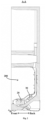
- FIG 1 is a schematic front view of an air-cooled refrigerator with an evaporator at a bottom of a cabinet according to the present invention.
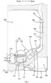
- Figure 2 is a schematic section view of the air-cooled refrigerator shown in Figure 1 .
- the refrigerator commonly may include the cabinet 10, and the cabinet 10 includes a shell, a liner and other accessories.
- the shell is an outer-layer structure of the refrigerator, and protects the whole refrigerator.
- the liners may be divided into a refrigerating liner, a variable temperature liner, a freezing liner, etc. according to functions, and the specific number and functions of the liners may be configured according to usage requirements of the refrigerator.
- the liner at least includes a bottom liner 110 commonly being the freezing liner.
- a compressor compartment 500 is limited at the rear of the bottom of the cabinet 10.
- the refrigerator in embodiments shown in Figure 3- Figure 9 is internally provided with a partition cover plate 120.
- the partition cover plate 120 is transversely arranged in the bottom liner 110 and used for dividing an internal space of the bottom liner 110 into a cooling chamber 100 and a storage space 200, and the cooling chamber 100 is located below the storage space 200.
- a return air cover 170 is arranged at a front portion of the cooling chamber 100, and a top of the return air cover 170 is connected to a front end of the partition cover plate 120.
- the return air cover 170 is provided with at least one front return air inlet communicating the cooling chamber 100 with the storage space 200, and air needed for heat exchange is provided for the cooling chamber 100 by the front return air inlet.
- the evaporator 20 is in a flat cuboid shape, and is arranged in the cooling chamber 100 in a manner of inclining upwards from front to back, where a front portion of a top surface of the evaporator 20, the partition cover plate 120 and the return air cover 170 define a frost-accommodating space 400, thereby enabling a part of air inflow from the front return air inlet to enter the evaporator 20 from the frost-accommodating space 400.
- An original return air flow deflection angle is changed by the frost-accommodating space 400, so that return air flow preferably flows through the frost-accommodating space 400 with low flow resistance and then flows through the evaporator 20, thereby preventing frost of the evaporator 20 from influencing the air flow, improving heat exchange efficiency, and further improving a refrigeration effect of the refrigerator.
- the refrigerator in the invention further includes a top heating wire 140.
- the top heating wire 140 is at least arranged at the front portion of the top surface of the evaporator 20 and configured to provide heat needed by defrosting for the evaporator 20.
- the top heating wire 140 may be only arranged at the front portion of the top surface of the evaporator 20, thereby facilitating arrangement of the heating wire for centralized defrosting.
- a defrosting effect can be improved, and overflow of hot airflow towards the storage space 200 can be avoided as well.
- the top heating wire 140 may cover the top surface of the whole evaporator 20, and density of the top heating wire 140 is adjusted according to different defrosting heat quantities needed for different positions of the top surface of the evaporator 20.
- the density of the top heating wire 140 arranged close to the front portion of the top surface of the evaporator 20 is the highest, and then, the density is sequentially reduced backwards, thereby providing enough heat for the frost-accommodating space 400 at the front of the evaporator 20, but the provided heat does not influence normal work of the evaporator 20.
- Power and actual temperature of the top heating wire 140 may be set section by section, and the temperature does not exceed 80 Celsius degrees, thereby effectively improving a safety level and guaranteeing a defrosting effect.
- a frosted position is transferred towards the frost-accommodating space 400 from the front portion of the evaporator 20, thereby facilitating centralized arrangement of the heating wire for defrosting.
- heated hot airflow rises, is stopped by the partition cover plate 120, and then is gathered in the frost-accommodating space 400.
- the defrosting effect can be improved, and overflow of the hot airflow towards the storage space 200 can be stopped, thereby improving a fresh keeping effect.
- An evaporator heat preservation part 130 is arranged between the partition cover plate 120 and the top of the evaporator 20.
- heat losses of the evaporator 20 can be reduced, and frosting even freezing of the surface of the evaporator 20 can be reduced.
- Cold energy on a surface of an evaporator 20 of a refrigerator in the prior art is likely to be diffused towards a storage space 200, which causes that a temperature of a bottom area of the storage space 200 is obviously lower than that of other parts of the storage space 200, and consequently, integral temperature distribution in the storage space 200 is uneven.
- the evaporator heat preservation part 130 solves the above problems. When the evaporator 20 is defrosted, the evaporator heat preservation part 130 can avoid temperature rise of the storage space 200 due to heat diffuse, namely, energy losses are avoided, and storage quality is prevented from being influenced.
- the evaporator heat preservation part 130 is formed by sequentially stacking a plurality of heat preservation layers different in material.
- the heat preservation layers include a heat preservation foam layer 1301, a resin film layer 1302 and a metal temperature equalization layer 1303.
- the heat preservation foam layer 1301 is attached to a lower surface of the partition cover plate 120.
- the heat preservation foam layer 1301 is light, has certain structure strength, and is arranged on the lower surface of the partition cover plate 120 so as to prevent large objects placed in the storage space 200 from impacting on the cabinet 10.
- the resin film layer 1302 is attached to a lower surface of the heat preservation foam layer 1301.
- the resin film layer 1302 may be set as a polyethylene film (PE film).
- the polyethylene film is low in specific weight and easily performs cover.
- the polyethylene film can be closely attached to the upper or lower heat preservation layer after shrinkage, thereby tightly connecting the heat preservation layers being high in integrality and not prone to separation.
- the polyethylene film is non-toxic, harmless, waterproof, bacteria-proofing, durable, and suitable for a service environment of the refrigerator.
- the metal temperature equalization layer 1303 is arranged on an outer side of the resin film layer 1302 and is opposite to the top of the evaporator 20.
- the metal temperature equalization layer 1303 may be set as aluminum foil.
- the aluminum foil is high in ductility, which can reduce a thickness of the metal temperature equalization layer 1303 to the maximum degree and prevent an internal space of the refrigerator from being occupied excessively; and the aluminum foil is excellent in heat-conducting property, thereby equalizing the temperature of the top of the evaporator 20, and solving a problem about uneven temperature distribution of the storage space 200 above the evaporator 20.
- the evaporator heat preservation part 130 includes a filling portion 131 and a heating wire limiting portion 132.
- An area, located behind the frost-accommodating space 400, between the partition cover plate 120 and the top surface of the evaporator 20 is filled with the filling portion 131.
- the heating wire limiting portion 132 extends forwards from the filling portion 131 and is provided with at least one downwards-protruding convex rib 1320 which can tightly press the top heating wire 140 on the top surface of the evaporator 20.
- a plurality of convex ribs 1320 are located above a transverse middle portion and two transverse sides of the top heating wire 140 respectively to fix the top heating wire 140 more stably.
- the heating wire limiting portion 132 is made into an E-shaped structure to limit a middle portion of the top heating wire 140 at the top surface of the evaporator 20.
- the metal temperature equalization layer 1303 is arranged in the evaporator heat preservation part 130 and makes contact with the top heating wire 140, which can effectively transfer energy and prevent a local temperature of the top heating wire 140 from being too high.
- the above settings simplify a limiting structure of the top heating wire 140, and the top heating wire 140 is fixed only through the evaporator heat preservation part 130 without additionally arranging an aluminum plate, thereby improving safety, simplifying the structure and facilitating installation.
- a bottom wall of the bottom liner 110 is further provided with a water receiving trough 111, and a bottom of the water receiving trough 111 is provided with a water outlet 112.
- the water outlet 112 guides defrosting water generated after defrosting into an evaporation dish 510 in the compressor compartment 500.
- the air-cooled refrigerator may further include a water pan 160.
- the water pan 160 is arranged between the evaporator 20 and the bottom wall of the bottom liner 110 and configured to receive water on the evaporator 20; and an area, opposite to the water receiving trough 111, of the water pan 160 is provided with a plurality of through holes used for guiding the defrosting water generated after defrosting into the water pan 160.
- the refrigerator in the embodiment further includes a bottom heating wire 150.
- the bottom heating wire 150 is coiled between the water pan 160 and the evaporator 20 and configured to provide heat for defrosting of the evaporator 20.
- the bottom heating wire 150 further includes: a front extension section 151 which extends to a position in front of the evaporator 20 from the bottom of the evaporator 20 and is used for heating and melting away frost falling down from the frost-accommodating space 400 during defrosting. In a defrosting process, the frost falling down from the frost-accommodating space 400 is melted away through the front extension section 151 of the bottom heating wire 150.
- the bottom heating wire 150 and the water pan 160 are fixed together, which can guarantee uniform heat transfer; and the water pan 160 may also have a safety protection function in a transportation process. Power density of the front extension section 151 does not exceed 10w/m due to less heat needed at the position, thereby effectively improving the safety level according to the design.
- Power of the bottom heating wire 150 and the top heating wire 140 is designed according to needs, which can guarantee the defrosting effect and meanwhile reduce energy waste and temperature rise of a freezer compartment, thereby improving the fresh keeping effect of the freezer compartment.
- the return air cover 170 in the embodiment is provided with a first front return air inlet 177 and a second front return air inlet 178.
- the first front return air inlet 177 is transversely formed in an upper portion of the return air cover 170.
- the second front return air inlet 178 is transversely formed in a lower portion of the return air cover 170, so that air in the storage space 200 flows towards the evaporator 20 from an upper area and a lower area.
- the return air cover 170 may include a first board 171, a second board 172, a third board 173, a fourth board 174, a fifth board 175 and a frame 176.
- the first board 171 extends obliquely downwards from back to front from the front end of the partition cover plate 120.
- the second board 172 extends obliquely downwards from front to back from a front end of the first board 171 to be concaved in a direction towards the cooling chamber 100.
- the first front return air inlet 177 is formed in the second board 172.
- the first front return air inlet 177 is formed by grid holes formed in the second board 172.
- a structure of a return air cover 170 in the prior art is likely to cause uneven return air volume distribution, airflow gathering nearby a return air inlet (e.g., a front end of an upper cover of the return air cover and an internal bending position of the upper cover of the return air cover), thus influencing air return efficiency.
- the second board 172 of the return air cover 170 in the embodiment inclines inwards, and thus, a set position of the first front return air inlet 177 extends in a direction towards the cooling chamber 100.
- the airflow When flowing through the first board 171, the airflow can be downwards guided due to downward inclination of the first board 171.
- the airflow When flowing through a corner towards an interior of the cooling chamber 100 formed by the first board 171 and the second board 172, the airflow may evenly flow into the cooling chamber 100 along with vortexes in the corner, thereby avoiding situations of uneven air volume distribution and gathering, improving air return efficiency and making air return smoother.
- a grid is formed at the front return air inlet.
- the grid holes are in a vertical strip shape and are sequentially distributed in a transverse direction to disperse return air, thereby enabling the return air to more evenly enter an upper section of the evaporator 20.
- the first front return air inlet 177 is basically flush with the top surface of the evaporator 20 in a vertical direction so that airflow entering the cooling chamber 100 from the first front return air inlet 177 can evenly exchange heat with the evaporator 20.
- the frost-accommodating space 400 is arranged at the front portion of the evaporator 20, which changes the original return air flow deflection angle, so that the airflow preferably flows through the frost-accommodating space 400 with low flow resistance and then flows through the evaporator 20, and thus airflow heat exchange in the evaporator 20 is more uniform. Setting a reasonable size of the frost-accommodating space 400 according to simulated analysis and frosting amount calculation can balance usage efficiency of the evaporator 20 before and after defrosting, thereby integrally improving the refrigeration effect.
- the third board 173 extends obliquely downwards from back to front from a rear end of the second board 172 to protrude forwards.
- the fourth board 174 extends obliquely downwards from front to back from a front end of the third board 173 to be concaved in a direction towards the cooling chamber 100.
- the fifth board 175 downwards obliquely extends backwards from a rear end of the fourth board 174.
- the second front return air inlet 178 is formed between the fifth board 175 and the frame 176, and is basically flush with a middle portion of the evaporator 20 in the vertical direction so that airflow entering the cooling chamber 100 from the second front return air inlet 178 can evenly exchange heat with the evaporator 20.
- the air-cooled refrigerator in the embodiment may further include an air duct back plate 180.
- the air duct back plate 180 is arranged in front of a rear wall 113 of the bottom liner 110 and defines, with the rear wall 113 of the bottom liner 110, an air supply duct 300; and the air duct back plate 180 is provided with at least one air supply port 181 used for communicating the air supply duct 300 with the storage space 200.
- the air duct back plate 180 may be further provided with water retaining ribs 182.
- the water retaining ribs 182 may be arranged on one side, towards a storage compartment, of the air duct back plate 180.
- transverse extension may refer to horizontal extension and may also be understood that the water retaining ribs 182 have a certain inclination angle. The two above manners both can reduce the falling speed of the condensate water on the water retaining ribs 182.
- a refrigeration fan 30 of the refrigerator in the embodiment is arranged behind the evaporator 20, an air outlet 310 of the refrigeration fan 30 is connected to a lower end of the air supply duct 300, and the refrigeration fan 30 is configured to promote formation of a refrigeration airflow which flows into the evaporator 20 from the front return air inlets and then is supplied to the air supply duct 300.
- the centrifugal fan may include a fan bottom shell 303, fan blades 302 and a fan upper cover 301.
- An air inlet of the centrifugal fan is commonly located in a center of the fan upper cover 301 and may be higher than a top end of the evaporator 20 to enlarge an air inlet space.
- the fan upper cover 301 and the air duct back plate 180 belong to a single-layer board formed through integrated injection molding, thereby simplifying installation steps.
- the front portion of the top surface of the evaporator 20, the partition cover plate 120 and the return air cover 170 define the frost-accommodating space 400, thereby enabling a part of air inflow from the front return air inlets to enter the evaporator 20 from the frost-accommodating space 400.
- the original return air flow deflection angle is changed by the frost-accommodating space 400, so that the return air flow preferably flows through the frost-accommodating space 400 with low flow resistance and then flows through the evaporator 20, thereby preventing frost of the evaporator 20 from influencing the air flow, improving heat exchange efficiency, and further improving the refrigeration effect of the refrigerator.
- the top heating wire 140 is arranged at the front portion of the top surface of the evaporator 20.
- the frost-accommodating space 400 By means of the frost-accommodating space 400, the frosted position is transferred into the frost-accommodating space from the front portion of the evaporator 20, and the top heating wire 140 is arranged at the front portion of the top surface of the evaporator 20 in a centralized manner, thereby preventing heat of the heating wire from influencing refrigeration work of the evaporator 20 during defrosting, optimizing a defrosting structure of the refrigerator, further improving the refrigeration efficiency of the refrigerator, and reducing energy consumption.
- the heating wire limiting portion 132 limits the top heating wire 140 at the top surface of the evaporator 20.
- the metal temperature equalization layer 1303 is arranged in the heating wire limiting portion 132 and makes contact with the top heating wire 140, which can effectively transfer energy and prevent the local temperature of the top heating wire 140 from being too high.
Landscapes
- Engineering & Computer Science (AREA)
- Chemical & Material Sciences (AREA)
- Combustion & Propulsion (AREA)
- Physics & Mathematics (AREA)
- Mechanical Engineering (AREA)
- Thermal Sciences (AREA)
- General Engineering & Computer Science (AREA)
- Defrosting Systems (AREA)
- Cold Air Circulating Systems And Constructional Details In Refrigerators (AREA)
- Devices That Are Associated With Refrigeration Equipment (AREA)
Claims (8)
- Luftgekühlter Kühlschrank (10) mit einem Verdampfer (20) am Boden eines Schranks, umfassend:den Schrank mit einer Bodenauskleidung (110);eine Trennabdeckplatte (120), die quer in der Bodenauskleidung (110) angeordnet ist und dazu dient, einen Innenraum der Bodenauskleidung (110) in eine Kühlkammer und einen Lagerraum zu unterteilen, wobei sich die Kühlkammer unterhalb des Lagerraums befindet;eine Rückluftabdeckung (170), die an einem vorderen Abschnitt der Kühlkammer angeordnet ist, wobei eine Oberseite der Rückluftabdeckung (170) mit einem vorderen Ende der Trennabdeckplatte (120) verbunden ist, die Rückluftabdeckung (170) mit mindestens einem vorderen Rücklufteinlass versehen ist, der die Kühlkammer mit dem Lagerraum verbindet, und für den Wärmeaustausch benötigte Luft der Kühlkammer durch den vorderen Rücklufteinlass zugeführt wird; undden Verdampfer (20), wobei der Verdampfer (20) eine flache Quaderform hat und in der Kühlkammer in einer Weise angeordnet ist, dass er sich von vorne nach hinten nach oben neigt, und ein vorderer Abschnitt einer oberen Fläche des Verdampfers (20), die Trennabdeckplatte (120) und die Rückluftabdeckung (170) einen frostaufnehmenden Raum definieren, wodurch ein Teil der vom vorderen Rücklufteinlass einströmenden Luft aus dem frostaufhaltenden Raum in den Verdampfer (20) eintritt, dadurch gekennzeichnet, dass er ferner umfasst:einen oberen Heizdraht (140), der zumindest am vorderen Abschnitt der oberen Oberfläche des Verdampfers (20) angeordnet und so konfiguriert ist, dass er die zum Abtauen des Verdampfers (20) benötigte Wärme liefert, undein Verdampfer-Wärmekonservierungsteil (130), das zwischen der Trennabdeckplatte undeiner Oberseite des Verdampfers angeordnet ist, und das umfasst:einen Füllabschnitt (131), mit dem ein Flächenbereich, der sich hinter dem frostaufnehmenden Raum befindet, zwischen der Trennabdeckplatte (120) und der oberen Oberfläche des Verdampfers (20) gefüllt wird; undeinen Heizdraht-Begrenzungsabschnitt (132), der sich von dem Füllabschnitt (131) nach vorne erstreckt und mit mindestens einer nach unten vorstehenden konvexen Rippe (1320) versehen ist, die den oberen Heizdraht (140) fest auf die obere Oberfläche des Verdampfers (20) drücken kann.
- Luftgekühlter Kühlschrank (10) mit einem Verdampfer (20) am Boden eines Schranks nach Anspruch 1, wobei
eine Vielzahl konvexer Rippen (1320) sich über einem mittleren Querabschnitt bzw. zwei Querseiten des oberen Heizdrahts (140) befinden. - Luftgekühlter Kühlschrank (10) mit einem Verdampfer (20) am Boden eines Schranks nach Anspruch 1 oder 2, wobei
der Verdampfer-Wärmekonservierungsteil (130) durch aufeinanderfolgendes Stapeln einer Vielzahl von Wärmekonservierungsschichten, die sich im Material unterscheiden, gebildet wird, und die Wärmekonservierungsschichten umfassen:eine Wärmekonservierungsschaumschicht (1301), die an einer unteren Fläche der Trennabdeckplatte (120) angebracht ist;eine Harzfilmschicht (1302), die an einer unteren Oberfläche der Wärmekonservierungsschaumschicht (1301) angebracht ist; undeine metallische Temperaturausgleichsschicht (1303), die auf einer Außenseite der Harzfilmschicht (1302) angeordnet ist und an dem oberen Heizdraht (140) anliegt. - Luftgekühlter Kühlschrank (10) mit einem Verdampfer (20) am Boden eines Schranks nach einem der Ansprüche 1 bis 3, wobei
eine Bodenwand der Bodenauskleidung (110) außerdem mit einer Wasseraufnahmerinne (111) versehen ist, und ein Boden der Wasseraufnahmerinne (111) ist mit einem Wasserauslass versehen; und der luftgekühlte Kühlschrank (10) umfasst weiterhin:eine Wasserwanne (160), die zwischen dem Verdampfer (20) und der Bodenwand der Bodenauskleidung (110) angeordnet und so konfiguriert ist, dass sie Wasser auf dem Verdampfer (20) aufnimmt, wobei ein der Wasseraufnahmerinne (111) gegenüberliegender Bereich der Wasserwanne (160) mit einer Vielzahl von Durchgangslöchern versehen ist; undeinen unteren Heizdraht (150), der zwischen der Wasserwanne (160) und dem Verdampfer (20) gewickelt und so konfiguriert ist, dass er Wärme zum Abtauen des Verdampfers (20) bereitstellt. - Luftgekühlter Kühlschrank (10) mit einem Verdampfer (20) am Boden eines Schranks nach Anspruch 4, wobei
der untere Heizdraht (150) ferner umfasst: einen vorderen Verlängerungsabschnitt, der sich von einem Boden des Verdampfers (20) zu einer Position vor dem Verdampfer (20) erstreckt und zum Erwärmen und Abschmelzen von Frost verwendet wird, der während des Abtauens von dem den frostaufnehmenden Raum herunterfällt. - Luftgekühlter Kühlschrank (10) mit einem Verdampfer (20) am Boden eines Schranks nach Anspruch 5, wobei
die Leistungsdichte des vorderen Verlängerungsabschnitts auf höchstens 10 W/m eingestellt ist. - Luftgekühlter Kühlschrank (10) mit einem Verdampfer (20) am Boden eines Schranks nach einem der Ansprüche 1 bis 6, wobei die Rückluftabdeckung (170) umfasst:einen ersten vorderen Rücklufteinlass, der quer in einem oberen Abschnitt der Rückluftabdeckung (170) ausgebildet ist; undeinen zweiten vorderen Rücklufteinlass, der quer in einem unteren Abschnitt der Rückluftabdeckung (170) ausgebildet ist, so dass die Luft im Lagerraum von einem oberen Bereich und einem unteren Bereich zum Verdampfer (20) strömt.
- Luftgekühlter Kühlschrank (10) mit dem Verdampfer (20) am Boden des Gehäuses nach einem der Ansprüche 1 bis 7, ferner umfassend:eine Luftkanal-Rückplatte, die vor einer Rückwand der Bodenauskleidung (110) angeordnet ist, mit der Rückwand der Bodenauskleidung (110) einen Luftzufuhrkanal definiert und mit mindestens einer Luftzufuhröffnung versehen ist, die zur Verbindung des Luftzufuhrkanals mit dem Lagerraum dient; undein Kühlgebläse (30), das hinter dem Verdampfer (20) angeordnet ist, wobei ein Luftauslass des Kühlgebläses mit einem unteren Ende des Luftzufuhrkanals verbunden ist und das Kühlgebläse so konfiguriert ist, dass es die Bildung eines Kühlluftstroms unterstützt, der von dem vorderen Rücklufteinlass in den Verdampfer (20) strömt und dann dem Luftzufuhrkanal zugeführt wird.
Priority Applications (1)
| Application Number | Priority Date | Filing Date | Title |
|---|---|---|---|
| EP24209533.9A EP4474737B1 (de) | 2020-08-18 | 2021-08-10 | Luftgekühlter kühlschrank mit am boden des schranks angeordnetem verdampfer |
Applications Claiming Priority (2)
| Application Number | Priority Date | Filing Date | Title |
|---|---|---|---|
| CN202010833950.8A CN114076466B (zh) | 2020-08-18 | 2020-08-18 | 蒸发器设置于箱体底部的风冷冰箱 |
| PCT/CN2021/111718 WO2022037437A1 (zh) | 2020-08-18 | 2021-08-10 | 蒸发器设置于箱体底部的风冷冰箱 |
Related Child Applications (1)
| Application Number | Title | Priority Date | Filing Date |
|---|---|---|---|
| EP24209533.9A Division EP4474737B1 (de) | 2020-08-18 | 2021-08-10 | Luftgekühlter kühlschrank mit am boden des schranks angeordnetem verdampfer |
Publications (3)
| Publication Number | Publication Date |
|---|---|
| EP4180748A1 EP4180748A1 (de) | 2023-05-17 |
| EP4180748A4 EP4180748A4 (de) | 2023-12-20 |
| EP4180748B1 true EP4180748B1 (de) | 2024-11-06 |
Family
ID=80281408
Family Applications (2)
| Application Number | Title | Priority Date | Filing Date |
|---|---|---|---|
| EP21857532.2A Active EP4180748B1 (de) | 2020-08-18 | 2021-08-10 | Luftgekühlter kühlschrank mit am boden des schranks angeordnetem verdampfer |
| EP24209533.9A Active EP4474737B1 (de) | 2020-08-18 | 2021-08-10 | Luftgekühlter kühlschrank mit am boden des schranks angeordnetem verdampfer |
Family Applications After (1)
| Application Number | Title | Priority Date | Filing Date |
|---|---|---|---|
| EP24209533.9A Active EP4474737B1 (de) | 2020-08-18 | 2021-08-10 | Luftgekühlter kühlschrank mit am boden des schranks angeordnetem verdampfer |
Country Status (5)
| Country | Link |
|---|---|
| US (2) | US12339053B2 (de) |
| EP (2) | EP4180748B1 (de) |
| CN (1) | CN114076466B (de) |
| AU (1) | AU2021329695B2 (de) |
| WO (1) | WO2022037437A1 (de) |
Families Citing this family (2)
| Publication number | Priority date | Publication date | Assignee | Title |
|---|---|---|---|---|
| CN114812051B (zh) * | 2022-05-25 | 2023-04-25 | 珠海格力电器股份有限公司 | 冰箱及其蒸发器化霜控制方法 |
| CN118149524B (zh) * | 2022-12-07 | 2026-03-06 | 青岛海尔电冰箱有限公司 | 冷藏冷冻装置 |
Family Cites Families (14)
| Publication number | Priority date | Publication date | Assignee | Title |
|---|---|---|---|---|
| US2994207A (en) | 1959-02-25 | 1961-08-01 | Gen Motors Corp | Refrigerating apparatus with defrosting controls |
| US3027735A (en) | 1960-01-25 | 1962-04-03 | Gen Motors Corp | Refrigerating apparatus |
| US3393530A (en) * | 1966-10-17 | 1968-07-23 | Whirlpool Co | Radiant defrost panel for refrigerator |
| EP1783445A1 (de) * | 2004-08-04 | 2007-05-09 | Hoshizaki Denki Kabushiki Kaisha | Kühllagerung |
| DE102010040362A1 (de) * | 2010-09-07 | 2012-03-08 | BSH Bosch und Siemens Hausgeräte GmbH | Gehäuse für ein Kältegerät |
| CN105783368A (zh) * | 2014-12-19 | 2016-07-20 | 博西华电器(江苏)有限公司 | 冰箱 |
| CN106005792B (zh) * | 2016-07-18 | 2018-10-23 | 苏州大福外贸食品有限公司 | 果蔬干雾控湿保鲜集装箱 |
| CN208817767U (zh) * | 2018-04-13 | 2019-05-03 | 青岛海尔股份有限公司 | 用于冰箱的蒸发器与冰箱 |
| CN110285629B (zh) * | 2018-04-13 | 2024-06-11 | 海尔智家股份有限公司 | 冷却室位于冷冻内胆内侧下部的冰箱 |
| CN110375504B (zh) * | 2018-04-13 | 2024-03-22 | 海尔智家股份有限公司 | 具有排水机构的冰箱 |
| CN108562094A (zh) * | 2018-06-26 | 2018-09-21 | 山东滨州冰天制冷设备有限公司 | 一种智能型速冻机 |
| CN209893734U (zh) | 2019-02-26 | 2020-01-03 | 青岛海尔电冰箱有限公司 | T型冰箱 |
| CN110285630B (zh) * | 2019-02-26 | 2020-03-06 | 青岛海尔电冰箱有限公司 | 冰箱 |
| CN211147012U (zh) | 2019-08-23 | 2020-07-31 | 青岛海尔特种电冰柜有限公司 | 风冷卧式冷柜 |
-
2020
- 2020-08-18 CN CN202010833950.8A patent/CN114076466B/zh active Active
-
2021
- 2021-08-10 AU AU2021329695A patent/AU2021329695B2/en active Active
- 2021-08-10 EP EP21857532.2A patent/EP4180748B1/de active Active
- 2021-08-10 WO PCT/CN2021/111718 patent/WO2022037437A1/zh not_active Ceased
- 2021-08-10 EP EP24209533.9A patent/EP4474737B1/de active Active
- 2021-08-10 US US18/020,970 patent/US12339053B2/en active Active
-
2025
- 2025-06-03 US US19/226,230 patent/US20250290683A1/en active Pending
Also Published As
| Publication number | Publication date |
|---|---|
| EP4474737A2 (de) | 2024-12-11 |
| EP4180748A1 (de) | 2023-05-17 |
| US20230288121A1 (en) | 2023-09-14 |
| EP4474737B1 (de) | 2026-05-13 |
| EP4180748A4 (de) | 2023-12-20 |
| US20250290683A1 (en) | 2025-09-18 |
| WO2022037437A1 (zh) | 2022-02-24 |
| EP4474737A3 (de) | 2025-02-26 |
| CN114076466A (zh) | 2022-02-22 |
| CN114076466B (zh) | 2023-01-20 |
| AU2021329695B2 (en) | 2024-05-02 |
| AU2021329695A1 (en) | 2023-03-02 |
| US12339053B2 (en) | 2025-06-24 |
Similar Documents
| Publication | Publication Date | Title |
|---|---|---|
| US20250290683A1 (en) | Air-cooled refrigerator with evaporator at bottom of cabinet | |
| US9175893B2 (en) | Refrigerator | |
| CN111947373A (zh) | 冰箱 | |
| CN113007950A (zh) | 一种风冷冰箱制冷模块及其冰箱 | |
| CN222364234U (zh) | 制冷电器 | |
| CN216716730U (zh) | 制冷设备的箱胆及制冷设备 | |
| WO2022037715A1 (zh) | 蒸发器布置于内胆底部的冰箱 | |
| CN216114890U (zh) | 冰箱 | |
| US12173953B2 (en) | Refrigerator | |
| CN202195636U (zh) | 冰箱 | |
| CN214581997U (zh) | 冷藏冷冻装置 | |
| CN221992160U (zh) | 制冷电器 | |
| CN214665473U (zh) | 一种风冷冰箱制冷模块及其冰箱 | |
| CN102937353B (zh) | 冰箱 | |
| CN116202268A (zh) | 冷柜 | |
| CN222418117U (zh) | 制冷电器 | |
| CN222364233U (zh) | 制冷电器 | |
| CN222364232U (zh) | 制冷电器 | |
| CN222849549U (zh) | 制冷电器 | |
| CN223710037U (zh) | 制冷箱胆以及制冷设备 | |
| CN219889921U (zh) | 一种冰箱 | |
| CN116412630A (zh) | 制冷设备的箱胆及制冷设备 | |
| CN116412631A (zh) | 制冷设备的箱胆及制冷设备 | |
| CN116412628A (zh) | 制冷设备的箱胆及制冷设备 | |
| CN116412629A (zh) | 制冷设备的箱胆及制冷设备 |
Legal Events
| Date | Code | Title | Description |
|---|---|---|---|
| STAA | Information on the status of an ep patent application or granted ep patent |
Free format text: STATUS: THE INTERNATIONAL PUBLICATION HAS BEEN MADE |
|
| PUAI | Public reference made under article 153(3) epc to a published international application that has entered the european phase |
Free format text: ORIGINAL CODE: 0009012 |
|
| STAA | Information on the status of an ep patent application or granted ep patent |
Free format text: STATUS: REQUEST FOR EXAMINATION WAS MADE |
|
| 17P | Request for examination filed |
Effective date: 20230210 |
|
| AK | Designated contracting states |
Kind code of ref document: A1 Designated state(s): AL AT BE BG CH CY CZ DE DK EE ES FI FR GB GR HR HU IE IS IT LI LT LU LV MC MK MT NL NO PL PT RO RS SE SI SK SM TR |
|
| DAV | Request for validation of the european patent (deleted) | ||
| DAX | Request for extension of the european patent (deleted) | ||
| STAA | Information on the status of an ep patent application or granted ep patent |
Free format text: STATUS: EXAMINATION IS IN PROGRESS |
|
| A4 | Supplementary search report drawn up and despatched |
Effective date: 20231116 |
|
| RIC1 | Information provided on ipc code assigned before grant |
Ipc: F25D 11/02 20060101AFI20231110BHEP |
|
| 17Q | First examination report despatched |
Effective date: 20231128 |
|
| GRAP | Despatch of communication of intention to grant a patent |
Free format text: ORIGINAL CODE: EPIDOSNIGR1 |
|
| STAA | Information on the status of an ep patent application or granted ep patent |
Free format text: STATUS: GRANT OF PATENT IS INTENDED |
|
| INTG | Intention to grant announced |
Effective date: 20240722 |
|
| GRAS | Grant fee paid |
Free format text: ORIGINAL CODE: EPIDOSNIGR3 |
|
| GRAA | (expected) grant |
Free format text: ORIGINAL CODE: 0009210 |
|
| STAA | Information on the status of an ep patent application or granted ep patent |
Free format text: STATUS: THE PATENT HAS BEEN GRANTED |
|
| AK | Designated contracting states |
Kind code of ref document: B1 Designated state(s): AL AT BE BG CH CY CZ DE DK EE ES FI FR GB GR HR HU IE IS IT LI LT LU LV MC MK MT NL NO PL PT RO RS SE SI SK SM TR |
|
| REG | Reference to a national code |
Ref country code: GB Ref legal event code: FG4D |
|
| REG | Reference to a national code |
Ref country code: CH Ref legal event code: EP |
|
| REG | Reference to a national code |
Ref country code: DE Ref legal event code: R096 Ref document number: 602021021617 Country of ref document: DE |
|
| REG | Reference to a national code |
Ref country code: IE Ref legal event code: FG4D |
|
| REG | Reference to a national code |
Ref country code: LT Ref legal event code: MG9D |
|
| REG | Reference to a national code |
Ref country code: NL Ref legal event code: MP Effective date: 20241106 |
|
| PG25 | Lapsed in a contracting state [announced via postgrant information from national office to epo] |
Ref country code: IS Free format text: LAPSE BECAUSE OF FAILURE TO SUBMIT A TRANSLATION OF THE DESCRIPTION OR TO PAY THE FEE WITHIN THE PRESCRIBED TIME-LIMIT Effective date: 20250306 Ref country code: HR Free format text: LAPSE BECAUSE OF FAILURE TO SUBMIT A TRANSLATION OF THE DESCRIPTION OR TO PAY THE FEE WITHIN THE PRESCRIBED TIME-LIMIT Effective date: 20241106 Ref country code: PT Free format text: LAPSE BECAUSE OF FAILURE TO SUBMIT A TRANSLATION OF THE DESCRIPTION OR TO PAY THE FEE WITHIN THE PRESCRIBED TIME-LIMIT Effective date: 20250306 |
|
| PG25 | Lapsed in a contracting state [announced via postgrant information from national office to epo] |
Ref country code: FI Free format text: LAPSE BECAUSE OF FAILURE TO SUBMIT A TRANSLATION OF THE DESCRIPTION OR TO PAY THE FEE WITHIN THE PRESCRIBED TIME-LIMIT Effective date: 20241106 Ref country code: NL Free format text: LAPSE BECAUSE OF FAILURE TO SUBMIT A TRANSLATION OF THE DESCRIPTION OR TO PAY THE FEE WITHIN THE PRESCRIBED TIME-LIMIT Effective date: 20241106 |
|
| REG | Reference to a national code |
Ref country code: AT Ref legal event code: MK05 Ref document number: 1739732 Country of ref document: AT Kind code of ref document: T Effective date: 20241106 |
|
| PG25 | Lapsed in a contracting state [announced via postgrant information from national office to epo] |
Ref country code: BG Free format text: LAPSE BECAUSE OF FAILURE TO SUBMIT A TRANSLATION OF THE DESCRIPTION OR TO PAY THE FEE WITHIN THE PRESCRIBED TIME-LIMIT Effective date: 20241106 |
|
| PG25 | Lapsed in a contracting state [announced via postgrant information from national office to epo] |
Ref country code: ES Free format text: LAPSE BECAUSE OF FAILURE TO SUBMIT A TRANSLATION OF THE DESCRIPTION OR TO PAY THE FEE WITHIN THE PRESCRIBED TIME-LIMIT Effective date: 20241106 |
|
| PG25 | Lapsed in a contracting state [announced via postgrant information from national office to epo] |
Ref country code: NO Free format text: LAPSE BECAUSE OF FAILURE TO SUBMIT A TRANSLATION OF THE DESCRIPTION OR TO PAY THE FEE WITHIN THE PRESCRIBED TIME-LIMIT Effective date: 20250206 |
|
| PG25 | Lapsed in a contracting state [announced via postgrant information from national office to epo] |
Ref country code: LV Free format text: LAPSE BECAUSE OF FAILURE TO SUBMIT A TRANSLATION OF THE DESCRIPTION OR TO PAY THE FEE WITHIN THE PRESCRIBED TIME-LIMIT Effective date: 20241106 Ref country code: AT Free format text: LAPSE BECAUSE OF FAILURE TO SUBMIT A TRANSLATION OF THE DESCRIPTION OR TO PAY THE FEE WITHIN THE PRESCRIBED TIME-LIMIT Effective date: 20241106 Ref country code: GR Free format text: LAPSE BECAUSE OF FAILURE TO SUBMIT A TRANSLATION OF THE DESCRIPTION OR TO PAY THE FEE WITHIN THE PRESCRIBED TIME-LIMIT Effective date: 20250207 |
|
| PG25 | Lapsed in a contracting state [announced via postgrant information from national office to epo] |
Ref country code: PL Free format text: LAPSE BECAUSE OF FAILURE TO SUBMIT A TRANSLATION OF THE DESCRIPTION OR TO PAY THE FEE WITHIN THE PRESCRIBED TIME-LIMIT Effective date: 20241106 |
|
| PG25 | Lapsed in a contracting state [announced via postgrant information from national office to epo] |
Ref country code: RS Free format text: LAPSE BECAUSE OF FAILURE TO SUBMIT A TRANSLATION OF THE DESCRIPTION OR TO PAY THE FEE WITHIN THE PRESCRIBED TIME-LIMIT Effective date: 20250206 |
|
| PG25 | Lapsed in a contracting state [announced via postgrant information from national office to epo] |
Ref country code: SM Free format text: LAPSE BECAUSE OF FAILURE TO SUBMIT A TRANSLATION OF THE DESCRIPTION OR TO PAY THE FEE WITHIN THE PRESCRIBED TIME-LIMIT Effective date: 20241106 |
|
| PG25 | Lapsed in a contracting state [announced via postgrant information from national office to epo] |
Ref country code: DK Free format text: LAPSE BECAUSE OF FAILURE TO SUBMIT A TRANSLATION OF THE DESCRIPTION OR TO PAY THE FEE WITHIN THE PRESCRIBED TIME-LIMIT Effective date: 20241106 |
|
| PG25 | Lapsed in a contracting state [announced via postgrant information from national office to epo] |
Ref country code: EE Free format text: LAPSE BECAUSE OF FAILURE TO SUBMIT A TRANSLATION OF THE DESCRIPTION OR TO PAY THE FEE WITHIN THE PRESCRIBED TIME-LIMIT Effective date: 20241106 |
|
| PG25 | Lapsed in a contracting state [announced via postgrant information from national office to epo] |
Ref country code: RO Free format text: LAPSE BECAUSE OF FAILURE TO SUBMIT A TRANSLATION OF THE DESCRIPTION OR TO PAY THE FEE WITHIN THE PRESCRIBED TIME-LIMIT Effective date: 20241106 |
|
| PG25 | Lapsed in a contracting state [announced via postgrant information from national office to epo] |
Ref country code: SK Free format text: LAPSE BECAUSE OF FAILURE TO SUBMIT A TRANSLATION OF THE DESCRIPTION OR TO PAY THE FEE WITHIN THE PRESCRIBED TIME-LIMIT Effective date: 20241106 |
|
| PG25 | Lapsed in a contracting state [announced via postgrant information from national office to epo] |
Ref country code: CZ Free format text: LAPSE BECAUSE OF FAILURE TO SUBMIT A TRANSLATION OF THE DESCRIPTION OR TO PAY THE FEE WITHIN THE PRESCRIBED TIME-LIMIT Effective date: 20241106 |
|
| PG25 | Lapsed in a contracting state [announced via postgrant information from national office to epo] |
Ref country code: IT Free format text: LAPSE BECAUSE OF FAILURE TO SUBMIT A TRANSLATION OF THE DESCRIPTION OR TO PAY THE FEE WITHIN THE PRESCRIBED TIME-LIMIT Effective date: 20241106 |
|
| REG | Reference to a national code |
Ref country code: DE Ref legal event code: R097 Ref document number: 602021021617 Country of ref document: DE |
|
| PG25 | Lapsed in a contracting state [announced via postgrant information from national office to epo] |
Ref country code: SE Free format text: LAPSE BECAUSE OF FAILURE TO SUBMIT A TRANSLATION OF THE DESCRIPTION OR TO PAY THE FEE WITHIN THE PRESCRIBED TIME-LIMIT Effective date: 20241106 |
|
| PLBE | No opposition filed within time limit |
Free format text: ORIGINAL CODE: 0009261 |
|
| STAA | Information on the status of an ep patent application or granted ep patent |
Free format text: STATUS: NO OPPOSITION FILED WITHIN TIME LIMIT |
|
| PGFP | Annual fee paid to national office [announced via postgrant information from national office to epo] |
Ref country code: DE Payment date: 20250812 Year of fee payment: 5 |
|
| 26N | No opposition filed |
Effective date: 20250807 |
|
| PGFP | Annual fee paid to national office [announced via postgrant information from national office to epo] |
Ref country code: GB Payment date: 20250826 Year of fee payment: 5 |
|
| PGFP | Annual fee paid to national office [announced via postgrant information from national office to epo] |
Ref country code: FR Payment date: 20250828 Year of fee payment: 5 |
|
| REG | Reference to a national code |
Ref country code: CH Ref legal event code: H13 Free format text: ST27 STATUS EVENT CODE: U-0-0-H10-H13 (AS PROVIDED BY THE NATIONAL OFFICE) Effective date: 20260324 |
|
| PG25 | Lapsed in a contracting state [announced via postgrant information from national office to epo] |
Ref country code: MC Free format text: LAPSE BECAUSE OF FAILURE TO SUBMIT A TRANSLATION OF THE DESCRIPTION OR TO PAY THE FEE WITHIN THE PRESCRIBED TIME-LIMIT Effective date: 20241106 |
|
| PG25 | Lapsed in a contracting state [announced via postgrant information from national office to epo] |
Ref country code: LU Free format text: LAPSE BECAUSE OF NON-PAYMENT OF DUE FEES Effective date: 20250810 |
|
| PG25 | Lapsed in a contracting state [announced via postgrant information from national office to epo] |
Ref country code: CH Free format text: LAPSE BECAUSE OF NON-PAYMENT OF DUE FEES Effective date: 20250831 |
|
| REG | Reference to a national code |
Ref country code: BE Ref legal event code: MM Effective date: 20250831 |
|
| PG25 | Lapsed in a contracting state [announced via postgrant information from national office to epo] |
Ref country code: LT Free format text: LAPSE BECAUSE OF FAILURE TO SUBMIT A TRANSLATION OF THE DESCRIPTION OR TO PAY THE FEE WITHIN THE PRESCRIBED TIME-LIMIT Effective date: 20241106 |
|
| PG25 | Lapsed in a contracting state [announced via postgrant information from national office to epo] |
Ref country code: IE Free format text: LAPSE BECAUSE OF NON-PAYMENT OF DUE FEES Effective date: 20250810 Ref country code: BE Free format text: LAPSE BECAUSE OF NON-PAYMENT OF DUE FEES Effective date: 20250831 |