EP4179934B1 - Behälter mit einem werkzeughalter, einem wandteil und einem kühlelement und mixer mit solch einem behälter - Google Patents
Behälter mit einem werkzeughalter, einem wandteil und einem kühlelement und mixer mit solch einem behälter Download PDFInfo
- Publication number
- EP4179934B1 EP4179934B1 EP21208481.8A EP21208481A EP4179934B1 EP 4179934 B1 EP4179934 B1 EP 4179934B1 EP 21208481 A EP21208481 A EP 21208481A EP 4179934 B1 EP4179934 B1 EP 4179934B1
- Authority
- EP
- European Patent Office
- Prior art keywords
- jar
- cooler element
- tool holder
- wall component
- blender
- Prior art date
- Legal status (The legal status is an assumption and is not a legal conclusion. Google has not performed a legal analysis and makes no representation as to the accuracy of the status listed.)
- Active
Links
Images

Classifications
-
- A—HUMAN NECESSITIES
- A47—FURNITURE; DOMESTIC ARTICLES OR APPLIANCES; COFFEE MILLS; SPICE MILLS; SUCTION CLEANERS IN GENERAL
- A47J—KITCHEN EQUIPMENT; COFFEE MILLS; SPICE MILLS; APPARATUS FOR MAKING BEVERAGES
- A47J43/00—Implements for preparing or holding food, not provided for in other groups of this subclass
- A47J43/04—Machines for domestic use not covered elsewhere, e.g. for grinding, mixing, stirring, kneading, emulsifying, whipping or beating foodstuffs, e.g. power-driven
- A47J43/07—Parts or details, e.g. mixing tools, whipping tools
- A47J43/0727—Mixing bowls
-
- A—HUMAN NECESSITIES
- A23—FOODS OR FOODSTUFFS; TREATMENT THEREOF, NOT COVERED BY OTHER CLASSES
- A23G—COCOA; COCOA PRODUCTS, e.g. CHOCOLATE; SUBSTITUTES FOR COCOA OR COCOA PRODUCTS; CONFECTIONERY; CHEWING GUM; ICE-CREAM; PREPARATION THEREOF
- A23G9/00—Frozen sweets, e.g. ice confectionery, ice-cream; Mixtures therefor
- A23G9/04—Production of frozen sweets, e.g. ice-cream
- A23G9/08—Batch production
- A23G9/12—Batch production using means for stirring the contents in a non-moving container
-
- A—HUMAN NECESSITIES
- A47—FURNITURE; DOMESTIC ARTICLES OR APPLIANCES; COFFEE MILLS; SPICE MILLS; SUCTION CLEANERS IN GENERAL
- A47J—KITCHEN EQUIPMENT; COFFEE MILLS; SPICE MILLS; APPARATUS FOR MAKING BEVERAGES
- A47J43/00—Implements for preparing or holding food, not provided for in other groups of this subclass
- A47J43/04—Machines for domestic use not covered elsewhere, e.g. for grinding, mixing, stirring, kneading, emulsifying, whipping or beating foodstuffs, e.g. power-driven
- A47J43/07—Parts or details, e.g. mixing tools, whipping tools
Definitions
- the present invention concerns a jar comprising a tool holder, a wall component and a cooler element.
- the invention further concerns a (stationary) blender with a base and such jar.
- Conventional blenders are devised for domestic use and typically comprise a jar and a base.
- the jar usually is composed of a knife holder configured to hold a blade assembly and forming a bottom of the jar, and a wall component detachably combinable to the knife holder so as to form the jar.
- the base comprises an electric motor and defines an operation position for the jar. In this position of the jar, the blade assembly held by the knife holder is coupled to the electric motor which thus is adapted to rotate the blade assembly. Thereby, food may be chopped, mixed and/or liquefied.
- Kitchen appliances with an additional cooling element are known, for example, from EP 3369353 A1 , US 4205535 A , DE 3806508 A1 , US 4696166 A and EP 3692799 A1 .
- the object is achieved by a jar according to claim 1, and by a blender according to claim 7.
- a jar according to the present invention belongs to a blender or is configured to form part of a blender.
- the jar comprises a tool holder, a wall component and a cooler element, which are detachably combinable.
- a combined state i.e., when the jar has been assembled, they together define a food reception space of the jar, the food reception space designated to receive food to be processed by the blender (in particular, by a tool the tool holder may hold).
- the cooler element i.e., a surface thereof at least partially delimits the food reception space.
- a blender according to the present invention comprises a jar according to an embodiment of the present invention, and a base defining an operation position of the jar and comprising an electric motor.
- the electric motor is coupled with a tool when this is (preferably detachably) fixed to the tool holder.
- the cooler element is designated to be put - prior to its utilisation - in a cooling environment such as a household refrigerator or a domestic freezer, and thus may be cooled therefrom.
- a cooling environment such as a household refrigerator or a domestic freezer
- the present invention thus facilitates that, if the cooler element has recently been taken out of the cooling environment before assembling and using the jar (along with a base of the blender), the temperature of the food being processed may be lowered due to its contact with the cooler element. Therefore, the present invention provides a convenient and easily employable passive cooling means for preparing, in a domestic environment, cool stirred and/or ground food such as frosty smoothies.
- the cooler element comprises one or more double-walled regions including a chamber which may contain a solution (such as salt water and/or urea) freezing at a temperature below 0°C.
- a solution such as salt water and/or urea
- the cooler element may preferably contain a latent heat accumulator which can comprise a phase change material.
- the cooler element is ring-shaped.
- the tool holder, the wall component and/or the cooler element may comprise means for a frictional connection (e.g., a (respective) screw thread) and/or means for a form-fit connection (such as at least one snap-lock means and/or at least one bayonet joint), which respectively may provide for detachably combining said components.
- the wall component, the cooler element and/or the tool holder may respectively comprise at least one fixation element (such as a pin, a screw thread and/or a cavity) configured to engage with at least one fixation element (such as a pin, a screw thread and/or a cavity) of a respective other one of the wall component, the cooler element and/or the tool holder.
- the cooler element at least partially delimits the food reception space in a bottom region thereof.
- it may at least partially delimit a lowest third or even a lowest fourth of the food reception space; in this document, the terms "bottom” and "low” and its derivatives each relate to an orientation designated for processing food in the assembled jar.
- a cooler element's surface delimiting the food reception space may advantageously at least partially abut a tool holder's surface facing (and also delimiting) the food reception space.
- the cooler element is detachably fixable to the tool holder so as to build a bottom part of the jar, and the wall component is then detachably fixable to the bottom part, in particular to the tool holder and/or to the cooler element thereof.
- the cooler element may be detachably fixable to the tool holder by means of at least one screw connection and/or at least one form-fit connection, such as at least one snap-lock means and/or at least one bayonet joint.
- the wall component may be detachably fixable to the bottom part by means of a screw connection or a form-fit connection, such as at least one snap-lock means and/or at least one bayonet joint.
- Such embodiments facilitate a particularly comfortable and quick assembly of the jar.
- the wall component may form a pipe with a first end and a second end, the first end surrounding a feed opening of the jar (i.e., through which in use of the jar food to be processed may be filled into the food reception space), the second end surrounding an opening configured to receive the tool holder and/or the cooler element when the wall component is combined thereto.
- the jar may also be shaped so that its horizontal section is not a circle or a circle-like shape but can also be a polygonal shape, for instance a hexagonal.
- the cooler element in a combined state of the tool holder, the wall component and the cooler element, is at least partially (in particular, entirely) surrounded by the wall component.
- the cooler element may be inserted in said opening at said second end of the wall component.
- the tool holder and the wall component are detachably combinable for use selectively with or without the cooler component. That is, the tool holder and the wall component are configured to be combined to each other even when omitting the cooler element, thus forming a components-reduced jar with a sealed further food reception space (which is enlarged as compared to the food reception space formed using the cooler element).
- Such embodiments facilitate utilisation of the blender
- cooler element for processing food not to be cooled also without the cooler element, for example while the cooler element is deposited in a cooling environment (such as a refrigerator or a freezer).
- a surface (of the jar) which at least partially delimits the food reception space may preferably have a profile comprising one or more protrusions (i.e. flow breaking elements).
- a profile may serve to obstruct food being processed by a rotating tool, and to redirect it towards the tool.
- at least one of such protrusions may extend over both a surface of the wall component and a cooler element's surface delimiting the food reception space.
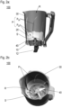
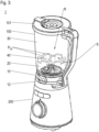
- FIGS 1a, 1b and 1c show a jar 100 according to an exemplary embodiment of the present invention in different states.
- the jar 100 comprises a tool holder 10, a cooler element 20 and a wall component 30.
- the cooler element 20 is ring-shaped, and a tool being a rotatable blade assembly 40 is held by the tool holder 10.
- the blade assembly 40 is detachably mounted to the tool holder 10.
- the tool holder 10 may advantageously be configured to selectively hold one of various tools, which may comprise different blade assemblies and/or beaters (not shown).
- the cooler element 20 may advantageously comprise at least one double walled region encasing a solution which freezes in a fridge and/or a household freezer. According to the invention, the cooler element 20 comprises a phase-change material.
- Figure 1a shows the tool holder 10, the cooler element 20 and the wall component 30 in an uncombined, i.e., disassembled state
- Figure 1b depicts a situation in which the cooler element 20 is detachably fixed to the tool holder 10.
- the tool holder 10 and the cooler element 20 together form a bottom part 110 of the jar 100.
- the cooler element 20 is detachably fixable to the tool holder 10 by means of a screw fitting, or by means of a form-fit connection such as a snap-lock and/or a bayonet joint (not visible in the figures).
- a seal ring 11 is configured to seal a contact region of the tool holder 10 and the cooler element 20 and/or a contact region of the tool holder 10 and the wall component 30.
- the wall component 30 is detachably fixable (such as by means of a screw fitting, or by means of a form-fit connection such as a snap-lock and/or a bayonet joint) to the bottom part 110, in particular to the tool holder 10 and/or to the cooler element 20 thereof.
- Figure 1c shows the jar 100 in such an assembled state, in which the tool holder 10, the cooler element 20 and the wall component 30 are combined.
- the cooler element 20 and the tool holder 10 are inserted in a bottom portion 31 of the wall component 30.
- the wall component 30 surrounds the ring-shaped cooler element 20.
- a pivotable handle 12 permits a user to easily grip and operate the bottom part 110 when fixing the wall component 30 to it, which fixing may comprise a linear and/or a rotational movement of the tool holder 10 relative to the wall component 30.
- the handle 12 may be pivoted so as to also be plunged in the bottom portion 31 of the wall component 30.
- the tool holder 10, the cooler element 20 and the wall component 30 together define a food reception space R of the jar 100, as is better shown in Figures 2a and 2b each providing a view in the jar 100 and, thereby, in the food reception space R.
- the jar 100 has a profile comprising protrusions P extending over both the wall component 30 and the cooler element 20.
- the protrusions P each have a section P 30 in which they are formed by the wall component 30, and a section P 20 in which they are formed by the cooler element 20.
- the protrusions P may serve to obstruct food when this is being processed by the rotating blade assembly 40, and to redirect it towards the blade assembly 40.
- these sections P 20 may provide for a particularly good capacity of holding cold.
- FIG 3 schematically illustrates the setup of a blender 1 according to an exemplary embodiment of the present invention.
- the blender 1 comprises a jar 100 and a base 200 containing an electric motor (not visible in Figure 3 ).
- an electric motor not visible in Figure 3
- the jar 100 and the cooler element 20 are depicted as partially transparent.
- a representation of the wall component's surface delimiting the food reception space R is omitted.
- the jar 100 is shown as being set in an operation position after the pivotable handle 12 has been swivelled so as to unblock a bottom surface of the jar 100.
- the electric motor is coupled with the blade assembly 40.
- the cooler element 20 may advantageously be combined, with the tool holder 10 and the wall component 30, after having been stored in a fridge or a household freezer, such as for several hours. Due to the cooler element 20 delimiting, with its surface S, the food reception space R of the assembled jar 100, food being processed in the jar 100 is then cooled by the cooler element 20. Thereby, cold drinks, in particular smoothies can be easily and conveniently made even in a domestic environment.
- a jar 100 for or of a blender 1 comprises a tool holder 10, a wall component 30 and a cooler element 20 which are detachably combinable such that, in a combined state, they define a food reception space R designated to receive food to be processed by the blender 1. Therein the cooler element 20 at least partially delimits the food reception space R.
- a (stationary) blender 1 with such jar 100 and a base 200, the base defining an operation position of the jar 100 and comprising an electric motor.
Landscapes
- Engineering & Computer Science (AREA)
- Food Science & Technology (AREA)
- Mechanical Engineering (AREA)
- Manufacturing & Machinery (AREA)
- Life Sciences & Earth Sciences (AREA)
- Chemical & Material Sciences (AREA)
- Polymers & Plastics (AREA)
- Food-Manufacturing Devices (AREA)
Claims (7)
- Behälter (100) für einen Mixer (1), wobei der Behälter einen Werkzeughalter (10), ein Wandteil (30) und ein Kühlelement (20) umfasst, die derart lösbar kombinierbar sind, dass sie in einem kombinierten Zustand einen Lebensmittelaufnahmeraum (R) definieren, der dazu bestimmt ist, durch den Mixer (1) zu verarbeitende Lebensmittel aufzunehmen, wobei das Kühlelement (20) den Lebensmittelaufnahmeraum (R) zumindest teilweise begrenzt, dadurch gekennzeichnet, dass das Kühlelement (20) mindestens einen doppelwandigen Bereich umfasst, der ein Phasenwechselmaterial umschließt, und dadurch, dass das Kühlelement (20) lösbar an dem Werkzeughalter (10) befestigbar ist, um ein Unterteil (110) des Behälters zu schaffen, und das Wandteil (30) lösbar an dem Unterteil (110) befestigbar ist.
- Behälter nach Anspruch 1, wobei das Kühlelement (20) durch eine formschlüssige Verbindung, insbesondere durch mindestens einen Schnappverschluss und/oder mindestens einer Bajonettverbindung, lösbar an dem Werkzeughalter (10) befestigbar ist.
- Behälter nach einem der vorhergehenden Ansprüche, wobei das Kühlelement (20) ringförmig ist.
- Behälter nach einem der vorhergehenden Ansprüche, wobei in dem kombinierten Zustand das Kühlelement (20) zumindest teilweise durch das Wandteil (30) umgeben ist.
- Behälter nach einem der vorhergehenden Ansprüche, wobei der Werkzeughalter (10) und das Wandteil (30) zur Verwendung wahlweise mit oder ohne das Kühlteil (20) kombinierbar sind.
- Behälter nach einem der vorhergehenden Ansprüche, wobei der Behälter an einer den Lebensmittelaufnahmeraum begrenzenden Fläche ein Profil aufweist, das einen oder mehrere Vorsprünge (P) umfasst, die sich sowohl über das Wandteil (30) als auch über das Kühlelement (20) erstrecken.
- Mixer (1) mit einem Behälter (100) nach einem der vorhergehenden Ansprüche und mit einer Basis (200), die einen Elektromotor umfasst und eine Betriebsposition für den Behälter definiert, wobei der Elektromotor in der Betriebsposition dazu konfiguriert ist, mit einem Werkzeug (40) gekoppelt zu sein, das an dem Werkzeughalter (10) befestigt ist.
Priority Applications (1)
| Application Number | Priority Date | Filing Date | Title |
|---|---|---|---|
| EP21208481.8A EP4179934B1 (de) | 2021-11-16 | 2021-11-16 | Behälter mit einem werkzeughalter, einem wandteil und einem kühlelement und mixer mit solch einem behälter |
Applications Claiming Priority (1)
| Application Number | Priority Date | Filing Date | Title |
|---|---|---|---|
| EP21208481.8A EP4179934B1 (de) | 2021-11-16 | 2021-11-16 | Behälter mit einem werkzeughalter, einem wandteil und einem kühlelement und mixer mit solch einem behälter |
Publications (3)
| Publication Number | Publication Date |
|---|---|
| EP4179934A1 EP4179934A1 (de) | 2023-05-17 |
| EP4179934B1 true EP4179934B1 (de) | 2025-04-02 |
| EP4179934C0 EP4179934C0 (de) | 2025-04-02 |
Family
ID=78676333
Family Applications (1)
| Application Number | Title | Priority Date | Filing Date |
|---|---|---|---|
| EP21208481.8A Active EP4179934B1 (de) | 2021-11-16 | 2021-11-16 | Behälter mit einem werkzeughalter, einem wandteil und einem kühlelement und mixer mit solch einem behälter |
Country Status (1)
| Country | Link |
|---|---|
| EP (1) | EP4179934B1 (de) |
Family Cites Families (5)
| Publication number | Priority date | Publication date | Assignee | Title |
|---|---|---|---|---|
| CH624278A5 (de) * | 1977-09-26 | 1981-07-31 | M & F Engineering Ag | |
| AT385631B (de) * | 1985-06-26 | 1988-04-25 | Philips Nv | Speiseeismaschine |
| DE3806508A1 (de) * | 1988-03-01 | 1989-09-14 | Norbert Flammann | Eismaschine |
| EP3369353A1 (de) * | 2017-03-01 | 2018-09-05 | Taurus Research and Development S.L.U. | Lebensmittelverarbeitungsvorrichtung zur herstellung von speiseeis |
| IT201900001727A1 (it) * | 2019-02-06 | 2020-08-06 | Smeg Spa | Accessorio gelatiera per una impastatrice, kit gelatiera per una impastatrice e impastatrice |
-
2021
- 2021-11-16 EP EP21208481.8A patent/EP4179934B1/de active Active
Also Published As
| Publication number | Publication date |
|---|---|
| EP4179934A1 (de) | 2023-05-17 |
| EP4179934C0 (de) | 2025-04-02 |
Similar Documents
| Publication | Publication Date | Title |
|---|---|---|
| EP3073839B1 (de) | Verbesserte sockelangetriebene vorrichtung und aufsätze | |
| EP3692799B1 (de) | Speiseeismaschine für einen standmixer, speiseeismaschinenkit für einen standmixer und standmixer | |
| EP3692873B1 (de) | Speiseeismaschine für einen standmixer, speiseeismaschinenkit für einen standmixer und standmixer | |
| US8388217B2 (en) | Cooling stick for a blender and method of using same | |
| US20220219965A1 (en) | Door and baffle interface assembly for frozen dessert machines | |
| CN207940303U (zh) | 一种带炒冰功能的冰淇淋机 | |
| EP2409576B1 (de) | Speiseeisbereitungsmaschine für den Hausgebrauch und professionellen Gebrauch | |
| US5360176A (en) | Blender | |
| US20140130538A1 (en) | Wooden ice cream maker | |
| CN110680211A (zh) | 具有冷却装置的制备容器 | |
| US20080257173A1 (en) | Dessert and ice cream making apparatus | |
| US20060156754A1 (en) | Apparatus for producing and dispensing a chilled or partially frozen beverage | |
| ES2776466T3 (es) | Aparato para preparar helados y productos congelados similares | |
| EP4179934B1 (de) | Behälter mit einem werkzeughalter, einem wandteil und einem kühlelement und mixer mit solch einem behälter | |
| US7412845B2 (en) | Ice cream maker including nestable canister assembly | |
| JPH0131030Y2 (de) | ||
| CA3240556A1 (en) | Micro puree machine | |
| MX2008014951A (es) | Metodo para la operacion de recipiente apropiado para la congelacion de su contenido y dispositivo para la preparacion de helado. | |
| CN101861503A (zh) | 用于大量热液体的快速流体冷却系统和方法及其所用的容器 | |
| CN113712451B (zh) | 一种厨师机 | |
| US20050105386A1 (en) | Mixing paddle for cooling a mixture | |
| JP2002176920A (ja) | ソフトクリーム製造機 | |
| US20220090839A1 (en) | Refrigeration and Freezer Pot | |
| KR200383275Y1 (ko) | 아이스크림 제조기 | |
| HK1055883A1 (en) | Kitchen machine with a stirrer vessel and method for the production of ice cream |
Legal Events
| Date | Code | Title | Description |
|---|---|---|---|
| PUAI | Public reference made under article 153(3) epc to a published international application that has entered the european phase |
Free format text: ORIGINAL CODE: 0009012 |
|
| STAA | Information on the status of an ep patent application or granted ep patent |
Free format text: STATUS: THE APPLICATION HAS BEEN PUBLISHED |
|
| AK | Designated contracting states |
Kind code of ref document: A1 Designated state(s): AL AT BE BG CH CY CZ DE DK EE ES FI FR GB GR HR HU IE IS IT LI LT LU LV MC MK MT NL NO PL PT RO RS SE SI SK SM TR |
|
| STAA | Information on the status of an ep patent application or granted ep patent |
Free format text: STATUS: REQUEST FOR EXAMINATION WAS MADE |
|
| 17P | Request for examination filed |
Effective date: 20231117 |
|
| RBV | Designated contracting states (corrected) |
Designated state(s): AL AT BE BG CH CY CZ DE DK EE ES FI FR GB GR HR HU IE IS IT LI LT LU LV MC MK MT NL NO PL PT RO RS SE SI SK SM TR |
|
| GRAP | Despatch of communication of intention to grant a patent |
Free format text: ORIGINAL CODE: EPIDOSNIGR1 |
|
| STAA | Information on the status of an ep patent application or granted ep patent |
Free format text: STATUS: GRANT OF PATENT IS INTENDED |
|
| INTG | Intention to grant announced |
Effective date: 20241121 |
|
| GRAS | Grant fee paid |
Free format text: ORIGINAL CODE: EPIDOSNIGR3 |
|
| GRAA | (expected) grant |
Free format text: ORIGINAL CODE: 0009210 |
|
| STAA | Information on the status of an ep patent application or granted ep patent |
Free format text: STATUS: THE PATENT HAS BEEN GRANTED |
|
| AK | Designated contracting states |
Kind code of ref document: B1 Designated state(s): AL AT BE BG CH CY CZ DE DK EE ES FI FR GB GR HR HU IE IS IT LI LT LU LV MC MK MT NL NO PL PT RO RS SE SI SK SM TR |
|
| REG | Reference to a national code |
Ref country code: GB Ref legal event code: FG4D |
|
| REG | Reference to a national code |
Ref country code: CH Ref legal event code: EP |
|
| REG | Reference to a national code |
Ref country code: IE Ref legal event code: FG4D |
|
| REG | Reference to a national code |
Ref country code: DE Ref legal event code: R096 Ref document number: 602021028451 Country of ref document: DE |
|
| U01 | Request for unitary effect filed |
Effective date: 20250416 |
|
| U07 | Unitary effect registered |
Designated state(s): AT BE BG DE DK EE FI FR IT LT LU LV MT NL PT RO SE SI Effective date: 20250424 |
|
| PG25 | Lapsed in a contracting state [announced via postgrant information from national office to epo] |
Ref country code: ES Free format text: LAPSE BECAUSE OF FAILURE TO SUBMIT A TRANSLATION OF THE DESCRIPTION OR TO PAY THE FEE WITHIN THE PRESCRIBED TIME-LIMIT Effective date: 20250402 |
|
| PG25 | Lapsed in a contracting state [announced via postgrant information from national office to epo] |
Ref country code: GR Free format text: LAPSE BECAUSE OF FAILURE TO SUBMIT A TRANSLATION OF THE DESCRIPTION OR TO PAY THE FEE WITHIN THE PRESCRIBED TIME-LIMIT Effective date: 20250703 Ref country code: NO Free format text: LAPSE BECAUSE OF FAILURE TO SUBMIT A TRANSLATION OF THE DESCRIPTION OR TO PAY THE FEE WITHIN THE PRESCRIBED TIME-LIMIT Effective date: 20250702 |
|
| PG25 | Lapsed in a contracting state [announced via postgrant information from national office to epo] |
Ref country code: PL Free format text: LAPSE BECAUSE OF FAILURE TO SUBMIT A TRANSLATION OF THE DESCRIPTION OR TO PAY THE FEE WITHIN THE PRESCRIBED TIME-LIMIT Effective date: 20250402 |
|
| PG25 | Lapsed in a contracting state [announced via postgrant information from national office to epo] |
Ref country code: HR Free format text: LAPSE BECAUSE OF FAILURE TO SUBMIT A TRANSLATION OF THE DESCRIPTION OR TO PAY THE FEE WITHIN THE PRESCRIBED TIME-LIMIT Effective date: 20250402 |
|
| PG25 | Lapsed in a contracting state [announced via postgrant information from national office to epo] |
Ref country code: RS Free format text: LAPSE BECAUSE OF FAILURE TO SUBMIT A TRANSLATION OF THE DESCRIPTION OR TO PAY THE FEE WITHIN THE PRESCRIBED TIME-LIMIT Effective date: 20250702 |
|
| PG25 | Lapsed in a contracting state [announced via postgrant information from national office to epo] |
Ref country code: IS Free format text: LAPSE BECAUSE OF FAILURE TO SUBMIT A TRANSLATION OF THE DESCRIPTION OR TO PAY THE FEE WITHIN THE PRESCRIBED TIME-LIMIT Effective date: 20250802 |