EP4179917B1 - Rückenlehne für einen gerätetaucher mit verstellbaren, mit einem lendengurt integrierten schulterriemen - Google Patents
Rückenlehne für einen gerätetaucher mit verstellbaren, mit einem lendengurt integrierten schulterriemen Download PDFInfo
- Publication number
- EP4179917B1 EP4179917B1 EP22203234.4A EP22203234A EP4179917B1 EP 4179917 B1 EP4179917 B1 EP 4179917B1 EP 22203234 A EP22203234 A EP 22203234A EP 4179917 B1 EP4179917 B1 EP 4179917B1
- Authority
- EP
- European Patent Office
- Prior art keywords
- pin
- strap
- backrest
- scuba diver
- lower portion
- Prior art date
- Legal status (The legal status is an assumption and is not a legal conclusion. Google has not performed a legal analysis and makes no representation as to the accuracy of the status listed.)
- Active
Links
Images
Classifications
-
- A—HUMAN NECESSITIES
- A45—HAND OR TRAVELLING ARTICLES
- A45F—TRAVELLING OR CAMP EQUIPMENT: SACKS OR PACKS CARRIED ON THE BODY
- A45F3/00—Travelling or camp articles; Sacks or packs carried on the body
- A45F3/14—Carrying-straps; Pack-carrying harnesses
-
- B—PERFORMING OPERATIONS; TRANSPORTING
- B63—SHIPS OR OTHER WATERBORNE VESSELS; RELATED EQUIPMENT
- B63C—LAUNCHING, HAULING-OUT, OR DRY-DOCKING OF VESSELS; LIFE-SAVING IN WATER; EQUIPMENT FOR DWELLING OR WORKING UNDER WATER; MEANS FOR SALVAGING OR SEARCHING FOR UNDERWATER OBJECTS
- B63C11/00—Equipment for dwelling or working underwater; Means for searching for underwater objects
- B63C11/02—Divers' equipment
-
- A—HUMAN NECESSITIES
- A45—HAND OR TRAVELLING ARTICLES
- A45F—TRAVELLING OR CAMP EQUIPMENT: SACKS OR PACKS CARRIED ON THE BODY
- A45F3/00—Travelling or camp articles; Sacks or packs carried on the body
- A45F3/14—Carrying-straps; Pack-carrying harnesses
- A45F2003/142—Carrying-straps
-
- B—PERFORMING OPERATIONS; TRANSPORTING
- B63—SHIPS OR OTHER WATERBORNE VESSELS; RELATED EQUIPMENT
- B63C—LAUNCHING, HAULING-OUT, OR DRY-DOCKING OF VESSELS; LIFE-SAVING IN WATER; EQUIPMENT FOR DWELLING OR WORKING UNDER WATER; MEANS FOR SALVAGING OR SEARCHING FOR UNDERWATER OBJECTS
- B63C11/00—Equipment for dwelling or working underwater; Means for searching for underwater objects
- B63C11/02—Divers' equipment
- B63C2011/026—Diving harnesses, or the like, e.g. for carrying breathing air tanks
-
- B—PERFORMING OPERATIONS; TRANSPORTING
- B63—SHIPS OR OTHER WATERBORNE VESSELS; RELATED EQUIPMENT
- B63C—LAUNCHING, HAULING-OUT, OR DRY-DOCKING OF VESSELS; LIFE-SAVING IN WATER; EQUIPMENT FOR DWELLING OR WORKING UNDER WATER; MEANS FOR SALVAGING OR SEARCHING FOR UNDERWATER OBJECTS
- B63C11/00—Equipment for dwelling or working underwater; Means for searching for underwater objects
- B63C11/02—Divers' equipment
- B63C11/18—Air supply
- B63C11/22—Air supply carried by diver
- B63C2011/2281—Devices for securing breathing gas tanks to diving harnesses, or back pieces of diving jackets, e.g. straps; Tensioning devices therefor
Definitions
- the present invention relates to a backrest for a scuba diver.
- Backrests for scuba divers that is, back support elements for one or more air cylinders for scuba diving, have been present on the market for some time in an extreme variety of shapes and sizes, both in a simple configuration and in a configuration integrated into a buoyancy control device (BCD), and are constrained to the scuba diver's body in various ways, generally with flexible straps.
- BCD buoyancy control device
- Patent application IT 102021000008921 of the same Applicant discloses a backrest for a scuba diver in which the release of the single strap constraining in the abdominal position maintains the constraint of the backrest on the diver's shoulders.
- US 3957183 A discloses an apparatus for carrying a tank of compressed breathing gas on the back of a user having a main back plate molded portion with handle openings and webs therein, and slits for receiving shoulder straps.
- the shoulder straps are looped through the back plate slits and webs in a continuous manner to form a combination shoulder, chest, and waist strap interconnected by means of two quick release fittings.
- connections of this type typically made of plastic materials, generally prove to be cumbersome and invasive for the diver, in particular in cave diving, where for safety reasons all the elements and accessories worn must be able to ensure utmost reliability against impacts with and entrapments between rocks or protrusions of any kind.
- the technical task of the present invention is to provide a backrest for a scuba diver that enables the aforementioned technical drawbacks of the prior art to be eliminated.
- one object of the invention is to provide a backrest for scuba divers provided with a single constraining strap that enables the constraints on the shoulders to be adjusted without acting on the constraint in the abdominal position.
- Another object of the invention is to provide a backrest for scuba divers provided with a single constraining strap that has adjustment elements which are not cumbersome.
- Yet a further object of the invention is to provide a backrest for scuba divers provided with a single constraining strap which enables a simple, effective and reversible adjustment of the constraints on the shoulders.
- each adjustment block has a bottom, two lateral walls, and a separating partition between said first pin and said second pin.
- the handgrip element is parallel to said bottom and the clamp element extends from said handgrip element in an angled direction in the direction of said second pin.
- the actuation of said clamp element between a position of blocking and a position of unblocking the sliding of said end of said lower portion of said strap around said second pin is configured as a rotation of said block around said first pin.
- the backrest is typically symmetrical with respect to a vertical axis Y; in the figures, similar reference numbers typically identify similar components, unless the context indicates otherwise.
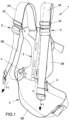
- the backrest for a scuba diver 1 comprises a shaped plate 2 for supporting at least one air cylinder, not shown in the figures.
- the shaped plate 2 comprises at least one lower right slide-through element 4 and a lower left slide-through element 4; a strap 3 is fixed to the shaped plate 2 and slides through the slide-through elements 4.
- the strap 3 comprises at least one upper right portion 3A configured to fit around the scuba diver's right shoulder and symmetrically an upper left portion 3A configured to fit around the scuba diver's left shoulder; the strap 3 comprises a lower portion 3B configured to fit around the scuba diver's abdomen.
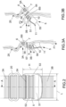
- the backrest 1 comprises a right adjustment block 5 between the upper right portion 3A and the lower portion 3B of the strap 3; symmetrically, the backrest 1 comprises a left adjustment block 5 between the upper left portion 3A and the lower portion 3B of the strap 3.
- Each adjustment block 5 has a width L that is greater than the width of the lower portion 3B of the strap 3 and a height H in the direction of the longitudinal axis of the lower portion 3B.
- Each of the adjustment blocks 5, the right one and the left one has a first pin 6 engaged in a first loop 7 of one end of the corresponding upper portion 3A of the strap 3, and a second pin 8 engaged in a second loop 9 of a corresponding end of the lower portion 3B of the strap 3.
- the end of the upper portion 3A is blocked from sliding over the first pin 6 by an adjustable blocking means 20.
- an adjustable blocking means 20 As an alternative to the adjustable blocking means 20, a stitched seam can be provided between the ends of the first loop 7, whereby the end of the upper portion 3A is blocked from sliding over the first pin 6.
- each adjustment block 5 has at least one clamp element 10 for clamping the lower portion 3B of said strap 3 to block the sliding of the end of the lower portion 3B of the strap 3 around the second pin 8.
- each adjustment block 5 has at least one handgrip element 11 for actuating the clamp element 10 between a position of blocking and a position of unblocking the sliding of the end of the lower portion 3B of the strap 3 around the second pin 8.
- Each adjustment block 5 is made up of a body having a bottom 51 and two opposing lateral walls 52, 53 that delimit the adjustment block 5 in the width L.
- the bottom 51 and the lateral walls 52, 53 delimit a cavity of the body of the adjustment block 5.
- the first pin 6 and the second pin 8 extend parallel in said cavity in the direction of the width L between the two lateral walls 52, 53.
- the separating partition extends transversely from the bottom 51.
- the handgrip element 11 is made up of a shaped edge of the bottom 51 that extends in the direction of the width L and delimits an opening 55 for the introduction of the diver's fingers in the cavity of the body of the block 5 for the actuation of the clamp element 10.
- the handgrip element 11 and the first pin 6 extend along opposite edges of the bottom 51 that delimit the adjustment block 5 in the width L.
- the clamp element 10 extends in the cavity of the body of the block 5 from the handgrip element 11 in an angled direction in the direction of the second pin 8.
- the bottom 51 has, on one side of the separating partition 54, a first slot 56 that extends in the direction of the width L for the passage of the first loop 7 wrapped around the first pin 6 and, on the other side of the separating partition 54, a second slot 57 and a third slot 58 that extend in the direction of the width L and are interposed between the separating partition 54 and the clamp element 10 for the passage of the second loop 9 wrapped around the second pin 8.
- both the first pin 6 and the second pin 8 have at least one or more protuberances 60i, 80i for engaging, in a blocked position, with the first loop 7 of the upper left portion and with the second loop 9 of the lower portion 3B of the strap 3, respectively.
- the adjustment block 5 is a monolithic piece, for instance but not necessarily made of thermoplastic polymeric resins.
- the actuation of the clamp element 10 between a position of blocking and a position of unblocking the sliding of the end of the lower portion 3B of the strap 3 around the second pin 8 is configured as a rotation of the block 5 around the first pin 6.
- the diver puts on the backrest 1, fitting the upper portions 3 A of the strap 3 around his shoulders and the portion 3B in the abdominal position; by adjusting the portion 3B by sliding it through the lower slide-through elements 4 he secures the backrest in a first position, the dorsal position.
- the first loop 7 of the end of the upper portion 3 A of the strap 3 is engaged in the first pin 6 of the block 5 and is blocked from sliding by the blocking means 20.
- the adjustment block 5 is in the blocking position: the second loop 9 of the end of the lower portion 3B of the strap 3 is engaged in the second pin 8 of the block 5 and is blocked from sliding by the clamp element 10 in the blocking position that counters the tension F1 on the lower portion of the strap 3B.
- the diver will act on the handgrip 11 and rotate the block 5 around the first pin 6; during the rotation, the clamp element 10 will be parallel to the lower portion of the strap 3B engaged around the second pin 8, and enable the consequent sliding thereof at a tension F2.
- the diver by acting on the handgrip 11 in a rotation opposite the unblocking one, will bring the clamp element 10 back to the forced engagement of the lower portion of strap 3B against the second pin 8, and hence the adjustment block 5 into the blocking position at the desired length of constraint of the strap 3 around his body.
- a backrest for a scuba diver provided with a single constraining strap according to the invention is particularly advantageous, as it enables the constraints on the shoulders to be adjusted without having to intervene on the constraint in the abdominal position.
- Another advantage of the invention is that of providing a backrest for a scuba diver provided with a single constraining strap having adjustment elements that are not cumbersome.
- Yet a further advantage of the invention is that of providing a backrest for a scuba diver provided with a single constraining strap which enables a simple, effective and reversible adjustment of the constraints on the shoulders.
Landscapes
- Engineering & Computer Science (AREA)
- Mechanical Engineering (AREA)
- Ocean & Marine Engineering (AREA)
- Helmets And Other Head Coverings (AREA)
- Orthopedics, Nursing, And Contraception (AREA)
- Portable Outdoor Equipment (AREA)
Claims (8)
- Eine Rückenstütze für einen Taucher (1), umfassend eine geformte Platte (2) zum Tragen von mindestens einer Druckluftflasche, wobei die geformte Platte (2) mindestens ein rechtes unteres Durchschiebeelement (4) und mindestens ein linkes unteres Durchschiebeelement (4) umfasst; ein linker Gurt (3) und ein rechter Gurt (3), die oben an der geformten Platte (2) befestigt und durch die genannten Durchschiebeelemente (4) verschiebbar sind, wobei sie einen oberen rechten Abschnitt (3A) aufweisen, der so konfiguriert ist, dass er sich um die rechte Schulter des Tauchers legt, einen oberen linken Abschnitt (3A), der so konfiguriert ist, dass er sich um die linke Schulter des Tauchers legt, sowie einen unteren linken Abschnitt (3B) und einen unteren rechten Abschnitt (3B), die so konfiguriert sind, dass sie sich um den Bauch des Tauchers legen, wobei der linke Gurt (3) und der rechte Gurt (3) jeweils einen rechten Einstellblock (5) zwischen dem oberen rechten Abschnitt (3A) und dem rechten unteren Abschnitt (3B) sowie einen linken Einstellblock (5) zwischen dem oberen linken Abschnitt (3A) und dem linken unteren Abschnitt (3B) umfassen, wobei jeder Einstellblock (5) einteilig ist und einen ersten Zapfen (6) aufweist, der in eine erste Schlaufe (7) eines Endes des oberen Abschnitts (3A) des Gurts (3) eingreift, einen zweiten Zapfen (8), der in eine zweite Schlaufe (9) eines Endes des unteren Abschnitts (3B) des Gurts (3) eingreift, ein Klemmenelement (10) zum Klemmen des unteren Abschnitts (3B) des Gurts (3), um das Gleiten dieses Endes des unteren Abschnitts (3B) des Gurts (3) um den zweiten Zapfen (8) zu blockieren, sowie ein Handgriff-Element (11) zur Betätigung des Klemmenelements (10) zwischen einer Blockierstellung und einer Freigabestellung des Gleitens des Endes des unteren Abschnitts (3B) des Gurts (3) um den zweiten Zapfen (8), dadurch gekennzeichnet, dass der erste Zapfen (6) und der zweite Zapfen (8) jeweils eine oder mehrere Vorsprünge (60i, 80i) zum Eingriff in einer blockierten Position jeweils mit der ersten Schlaufe (7) des oberen Abschnitts (3A) und mit der zweiten Schlaufe (9) des unteren Abschnitts (3B) des Gurts (3) aufweisen, und dass der untere Abschnitt (3B) zur Einstellung durch das Durchschiebeelement (4) verschiebbar ist, um die Rückenstütze in einer ersten Position, der Rückenlage, zu sichern.
- Die Rückenstütze für einen Taucher (1) nach dem vorhergehenden Anspruch, dadurch gekennzeichnet, dass das Klemmenelement (10) sich von dem Handgriff-Element (11) in einem Winkel in Richtung des zweiten Zapfens (8) erstreckt.
- Die Rückenstütze für einen Taucher (1) nach einem der vorhergehenden Ansprüche, dadurch gekennzeichnet, dass die Betätigung des Klemmenelements (10) zwischen einer Blockierstellung und einer Freigabestellung des Gleitens des Endes des unteren Abschnitts (3B) des Gurts (3) um den zweiten Zapfen (8) als eine Drehbewegung des Blocks (5) um den ersten Zapfen (6) konfiguriert ist.
- Die Rückenstütze für einen Taucher (1) nach einem der vorhergehenden Ansprüche, dadurch gekennzeichnet, dass das Ende des oberen Abschnitts (3A) durch ein Blockiermittel (20) gegen ein Gleiten über den ersten Zapfen (6) gesichert ist.
- Die Rückenstütze für einen Taucher (1) nach einem der vorhergehenden Ansprüche, dadurch gekennzeichnet, dass jeder Einstellblock (5) einen Boden (51) und zwei gegenüberliegende Seitenwände (52, 53) aufweist, die die Breite (L) des Einstellblocks (5) begrenzen, wobei der Boden (51) und die gegenüberliegenden Seitenwände (52, 53) einen Hohlraum im Körper des Einstellblocks (5) begrenzen.
- Die Rückenstütze für einen Taucher (1) nach dem vorhergehenden Anspruch, dadurch gekennzeichnet, dass der erste Zapfen (6) und der zweite Zapfen (8) parallel in dem Hohlraum in Richtung der Breite (L) zwischen den gegenüberliegenden Seitenwänden (52, 53) verlaufen.
- Die Rückenstütze für einen Taucher (1) nach dem vorhergehenden Anspruch, dadurch gekennzeichnet, dass eine Trennwand (54) in dem Hohlraum zwischen dem ersten Zapfen (6) und dem zweiten Zapfen (8) angeordnet ist.
- Die Rückenstütze für einen Taucher (1) nach einem der vorhergehenden Ansprüche 5 bis 7, dadurch gekennzeichnet, dass das Handgriff-Element (11) durch einen geformten Rand des Bodens (51) gebildet ist, der sich in Richtung der Breite (L) erstreckt und eine Öffnung (55) begrenzt, durch die die Finger des Tauchers in den Hohlraum des Körpers des Blocks (5) zur Betätigung des Klemmenelements (10) eingeführt werden können.
Applications Claiming Priority (1)
| Application Number | Priority Date | Filing Date | Title |
|---|---|---|---|
| IT202100028811 | 2021-11-12 |
Publications (3)
| Publication Number | Publication Date |
|---|---|
| EP4179917A1 EP4179917A1 (de) | 2023-05-17 |
| EP4179917C0 EP4179917C0 (de) | 2025-06-04 |
| EP4179917B1 true EP4179917B1 (de) | 2025-06-04 |
Family
ID=79831327
Family Applications (1)
| Application Number | Title | Priority Date | Filing Date |
|---|---|---|---|
| EP22203234.4A Active EP4179917B1 (de) | 2021-11-12 | 2022-10-24 | Rückenlehne für einen gerätetaucher mit verstellbaren, mit einem lendengurt integrierten schulterriemen |
Country Status (4)
| Country | Link |
|---|---|
| US (1) | US12515770B2 (de) |
| EP (1) | EP4179917B1 (de) |
| CN (1) | CN116118978A (de) |
| ES (1) | ES3039007T3 (de) |
Citations (3)
| Publication number | Priority date | Publication date | Assignee | Title |
|---|---|---|---|---|
| DE1255373B (de) * | 1964-12-05 | 1967-11-30 | Lindblad O L | Einstueckige Gurtschnalle, insbesondere fuer Sicherheitsgurte |
| US5651166A (en) * | 1995-11-13 | 1997-07-29 | Illinois Tool Works Inc. | Method and apparatus for anti-slip webbing adjustment |
| US20050086772A1 (en) * | 2003-10-28 | 2005-04-28 | Manabu Yoshiguchi | Buckle |
Family Cites Families (15)
| Publication number | Priority date | Publication date | Assignee | Title |
|---|---|---|---|---|
| US3065888A (en) * | 1959-03-02 | 1962-11-27 | Irving W Lande | Skin diving harness construction |
| US3033431A (en) * | 1960-08-08 | 1962-05-08 | Robert B Henderson | Back plate for self-contained underwater breathing apparatus |
| US3219242A (en) | 1963-09-06 | 1965-11-23 | Seamless Rubber Co | Backpack for air tank for underwater divers |
| SE313259B (de) * | 1964-12-05 | 1969-08-04 | O Lindblad | |
| US3957183A (en) * | 1974-03-14 | 1976-05-18 | U.S. Divers Company | Backpack for breathing tanks |
| AU559643B2 (en) * | 1983-12-29 | 1987-03-19 | Nippon Notion Kogyo Co. Ltd. | Adjustable strap fastener |
| US5243741A (en) * | 1991-11-29 | 1993-09-14 | Yoshida Kogyo K.K. | Buckle |
| JP3281337B2 (ja) * | 1999-08-27 | 2002-05-13 | 株式会社タバタ | ダイビング用ジャケット |
| JP3693579B2 (ja) * | 2001-02-15 | 2005-09-07 | 株式会社タバタ | 潜水用浮力調整器 |
| USD523920S1 (en) | 2004-07-01 | 2006-06-27 | Cresswell Gary A | Scuba tank backplate |
| JP4253624B2 (ja) * | 2004-08-12 | 2009-04-15 | 株式会社タバタ | 浮力調整器のシリンダバンド |
| JP4674132B2 (ja) * | 2005-07-29 | 2011-04-20 | Ykk株式会社 | ベルト調節具 |
| US8398337B2 (en) | 2009-06-05 | 2013-03-19 | Halcyon Manufacturing, Inc. | Continuous weave quick harness backplate system |
| US8407866B2 (en) * | 2009-10-30 | 2013-04-02 | Illinois Tool Works Inc. | Foldable attachment clip |
| US10772389B2 (en) * | 2017-09-15 | 2020-09-15 | Johnson Outdoors Inc. | Quick fit tank cinch |
-
2022
- 2022-10-20 CN CN202211285353.1A patent/CN116118978A/zh active Pending
- 2022-10-24 EP EP22203234.4A patent/EP4179917B1/de active Active
- 2022-10-24 ES ES22203234T patent/ES3039007T3/es active Active
- 2022-10-26 US US17/974,225 patent/US12515770B2/en active Active
Patent Citations (3)
| Publication number | Priority date | Publication date | Assignee | Title |
|---|---|---|---|---|
| DE1255373B (de) * | 1964-12-05 | 1967-11-30 | Lindblad O L | Einstueckige Gurtschnalle, insbesondere fuer Sicherheitsgurte |
| US5651166A (en) * | 1995-11-13 | 1997-07-29 | Illinois Tool Works Inc. | Method and apparatus for anti-slip webbing adjustment |
| US20050086772A1 (en) * | 2003-10-28 | 2005-04-28 | Manabu Yoshiguchi | Buckle |
Also Published As
| Publication number | Publication date |
|---|---|
| CN116118978A (zh) | 2023-05-16 |
| EP4179917A1 (de) | 2023-05-17 |
| ES3039007T3 (en) | 2025-10-16 |
| US20230150627A1 (en) | 2023-05-18 |
| EP4179917C0 (de) | 2025-06-04 |
| US12515770B2 (en) | 2026-01-06 |
Similar Documents
| Publication | Publication Date | Title |
|---|---|---|
| US5641247A (en) | Combination spider and buoyancy compensator with insertable weights | |
| US5607258A (en) | Scuba diving harness for use with a buoyancy control device | |
| JP2558028B2 (ja) | 潜水用浮力調整器 | |
| US4545773A (en) | Sailboarding personal flotation device | |
| US5451121A (en) | Combination buoyancy compensator, spider, and backpack with securement and suspension system | |
| US4690314A (en) | Buoyancy compensator insertable backpack | |
| US11814145B2 (en) | Backrest for scuba diving with a single strap adjustment system | |
| US11583752B2 (en) | Harness with single-pull adjustment | |
| ITUB20156004A1 (it) | Giubbotto ad assetto variabile per uso subacqueo | |
| EP3581062A1 (de) | Schulterriemen zum tragen von rückenlasten, vorrichtung zum tragen von rückenlasten und insbesondere eine tarierweste oder dergleichen | |
| EP4179917B1 (de) | Rückenlehne für einen gerätetaucher mit verstellbaren, mit einem lendengurt integrierten schulterriemen | |
| US6808046B1 (en) | Body harness | |
| CN107823814A (zh) | 配有人体工学连接点的系带 | |
| EP4180317B1 (de) | Rückenlehne mit einer stütze zur befestigung einer gewichtstasche | |
| EP4106884B1 (de) | Tauchgeschirr | |
| US20020042584A1 (en) | Flexible back brace | |
| CN212166353U (zh) | 一种救生型安全带 | |
| US6638126B2 (en) | Personal floatation device | |
| CN219205975U (zh) | 护腰带 | |
| EP1389434B1 (de) | Vorrichtung zum Halten der freien Enden von Spannbändern, Gürteln oder dergleichen, insbesondere für Bekleidungsartikel und Tauchauftriebkompensatorweste mit so einer Vorrichtung | |
| CN218773981U (zh) | 护腰带 | |
| CN219165712U (zh) | 护腰带 | |
| CN219165713U (zh) | 护腰带 | |
| RU2684251C1 (ru) | Единая модульная система плавучести подводного пловца | |
| CN219020238U (zh) | 护腰带 |
Legal Events
| Date | Code | Title | Description |
|---|---|---|---|
| PUAI | Public reference made under article 153(3) epc to a published international application that has entered the european phase |
Free format text: ORIGINAL CODE: 0009012 |
|
| STAA | Information on the status of an ep patent application or granted ep patent |
Free format text: STATUS: THE APPLICATION HAS BEEN PUBLISHED |
|
| AK | Designated contracting states |
Kind code of ref document: A1 Designated state(s): AL AT BE BG CH CY CZ DE DK EE ES FI FR GB GR HR HU IE IS IT LI LT LU LV MC ME MK MT NL NO PL PT RO RS SE SI SK SM TR |
|
| STAA | Information on the status of an ep patent application or granted ep patent |
Free format text: STATUS: REQUEST FOR EXAMINATION WAS MADE |
|
| P01 | Opt-out of the competence of the unified patent court (upc) registered |
Effective date: 20230522 |
|
| 17P | Request for examination filed |
Effective date: 20230620 |
|
| RBV | Designated contracting states (corrected) |
Designated state(s): AL AT BE BG CH CY CZ DE DK EE ES FI FR GB GR HR HU IE IS IT LI LT LU LV MC ME MK MT NL NO PL PT RO RS SE SI SK SM TR |
|
| STAA | Information on the status of an ep patent application or granted ep patent |
Free format text: STATUS: EXAMINATION IS IN PROGRESS |
|
| 17Q | First examination report despatched |
Effective date: 20231213 |
|
| RIC1 | Information provided on ipc code assigned before grant |
Ipc: B63C 11/02 20060101ALN20241030BHEP Ipc: A45F 3/04 20060101AFI20241030BHEP |
|
| RIC1 | Information provided on ipc code assigned before grant |
Ipc: B63C 11/02 20060101ALN20241114BHEP Ipc: A45F 3/04 20060101AFI20241114BHEP |
|
| GRAP | Despatch of communication of intention to grant a patent |
Free format text: ORIGINAL CODE: EPIDOSNIGR1 |
|
| STAA | Information on the status of an ep patent application or granted ep patent |
Free format text: STATUS: GRANT OF PATENT IS INTENDED |
|
| RIC1 | Information provided on ipc code assigned before grant |
Ipc: B63C 11/02 20060101ALN20241209BHEP Ipc: A45F 3/04 20060101AFI20241209BHEP |
|
| INTG | Intention to grant announced |
Effective date: 20250107 |
|
| GRAS | Grant fee paid |
Free format text: ORIGINAL CODE: EPIDOSNIGR3 |
|
| GRAA | (expected) grant |
Free format text: ORIGINAL CODE: 0009210 |
|
| STAA | Information on the status of an ep patent application or granted ep patent |
Free format text: STATUS: THE PATENT HAS BEEN GRANTED |
|
| AK | Designated contracting states |
Kind code of ref document: B1 Designated state(s): AL AT BE BG CH CY CZ DE DK EE ES FI FR GB GR HR HU IE IS IT LI LT LU LV MC ME MK MT NL NO PL PT RO RS SE SI SK SM TR |
|
| REG | Reference to a national code |
Ref country code: GB Ref legal event code: FG4D |
|
| REG | Reference to a national code |
Ref country code: CH Ref legal event code: EP |
|
| REG | Reference to a national code |
Ref country code: DE Ref legal event code: R096 Ref document number: 602022015425 Country of ref document: DE |
|
| REG | Reference to a national code |
Ref country code: IE Ref legal event code: FG4D |
|
| U01 | Request for unitary effect filed |
Effective date: 20250624 |
|
| U07 | Unitary effect registered |
Designated state(s): AT BE BG DE DK EE FI FR IT LT LU LV MT NL PT RO SE SI Effective date: 20250701 |
|
| P04 | Withdrawal of opt-out of the competence of the unified patent court (upc) registered |
Free format text: CASE NUMBER: APP_30996/2025 Effective date: 20250627 |
|
| PG25 | Lapsed in a contracting state [announced via postgrant information from national office to epo] |
Ref country code: GR Free format text: LAPSE BECAUSE OF FAILURE TO SUBMIT A TRANSLATION OF THE DESCRIPTION OR TO PAY THE FEE WITHIN THE PRESCRIBED TIME-LIMIT Effective date: 20250905 Ref country code: NO Free format text: LAPSE BECAUSE OF FAILURE TO SUBMIT A TRANSLATION OF THE DESCRIPTION OR TO PAY THE FEE WITHIN THE PRESCRIBED TIME-LIMIT Effective date: 20250904 |
|
| PG25 | Lapsed in a contracting state [announced via postgrant information from national office to epo] |
Ref country code: PL Free format text: LAPSE BECAUSE OF FAILURE TO SUBMIT A TRANSLATION OF THE DESCRIPTION OR TO PAY THE FEE WITHIN THE PRESCRIBED TIME-LIMIT Effective date: 20250604 |
|
| REG | Reference to a national code |
Ref country code: ES Ref legal event code: FG2A Ref document number: 3039007 Country of ref document: ES Kind code of ref document: T3 Effective date: 20251016 |
|
| PG25 | Lapsed in a contracting state [announced via postgrant information from national office to epo] |
Ref country code: HR Free format text: LAPSE BECAUSE OF FAILURE TO SUBMIT A TRANSLATION OF THE DESCRIPTION OR TO PAY THE FEE WITHIN THE PRESCRIBED TIME-LIMIT Effective date: 20250604 |
|
| PG25 | Lapsed in a contracting state [announced via postgrant information from national office to epo] |
Ref country code: RS Free format text: LAPSE BECAUSE OF FAILURE TO SUBMIT A TRANSLATION OF THE DESCRIPTION OR TO PAY THE FEE WITHIN THE PRESCRIBED TIME-LIMIT Effective date: 20250904 |
|
| U20 | Renewal fee for the european patent with unitary effect paid |
Year of fee payment: 4 Effective date: 20251022 |
|
| PG25 | Lapsed in a contracting state [announced via postgrant information from national office to epo] |
Ref country code: IS Free format text: LAPSE BECAUSE OF FAILURE TO SUBMIT A TRANSLATION OF THE DESCRIPTION OR TO PAY THE FEE WITHIN THE PRESCRIBED TIME-LIMIT Effective date: 20251004 |
|
| PG25 | Lapsed in a contracting state [announced via postgrant information from national office to epo] |
Ref country code: SM Free format text: LAPSE BECAUSE OF FAILURE TO SUBMIT A TRANSLATION OF THE DESCRIPTION OR TO PAY THE FEE WITHIN THE PRESCRIBED TIME-LIMIT Effective date: 20250604 |
|
| PG25 | Lapsed in a contracting state [announced via postgrant information from national office to epo] |
Ref country code: CZ Free format text: LAPSE BECAUSE OF FAILURE TO SUBMIT A TRANSLATION OF THE DESCRIPTION OR TO PAY THE FEE WITHIN THE PRESCRIBED TIME-LIMIT Effective date: 20250604 |
|
| PG25 | Lapsed in a contracting state [announced via postgrant information from national office to epo] |
Ref country code: SK Free format text: LAPSE BECAUSE OF FAILURE TO SUBMIT A TRANSLATION OF THE DESCRIPTION OR TO PAY THE FEE WITHIN THE PRESCRIBED TIME-LIMIT Effective date: 20250604 |
|
| PGFP | Annual fee paid to national office [announced via postgrant information from national office to epo] |
Ref country code: ES Payment date: 20251118 Year of fee payment: 4 |