EP4177600A1 - X-ray analysis apparatus - Google Patents
X-ray analysis apparatus Download PDFInfo
- Publication number
- EP4177600A1 EP4177600A1 EP20943512.2A EP20943512A EP4177600A1 EP 4177600 A1 EP4177600 A1 EP 4177600A1 EP 20943512 A EP20943512 A EP 20943512A EP 4177600 A1 EP4177600 A1 EP 4177600A1
- Authority
- EP
- European Patent Office
- Prior art keywords
- sample
- holder
- container
- placement portion
- opening
- Prior art date
- Legal status (The legal status is an assumption and is not a legal conclusion. Google has not performed a legal analysis and makes no representation as to the accuracy of the status listed.)
- Granted
Links
Images

Classifications
-
- G—PHYSICS
- G01—MEASURING; TESTING
- G01N—INVESTIGATING OR ANALYSING MATERIALS BY DETERMINING THEIR CHEMICAL OR PHYSICAL PROPERTIES
- G01N23/00—Investigating or analysing materials by the use of wave or particle radiation, e.g. X-rays or neutrons, not covered by groups G01N3/00 – G01N17/00, G01N21/00 or G01N22/00
- G01N23/22—Investigating or analysing materials by the use of wave or particle radiation, e.g. X-rays or neutrons, not covered by groups G01N3/00 – G01N17/00, G01N21/00 or G01N22/00 by measuring secondary emission from the material
- G01N23/223—Investigating or analysing materials by the use of wave or particle radiation, e.g. X-rays or neutrons, not covered by groups G01N3/00 – G01N17/00, G01N21/00 or G01N22/00 by measuring secondary emission from the material by irradiating the sample with X-rays or gamma-rays and by measuring X-ray fluorescence
-
- G—PHYSICS
- G01—MEASURING; TESTING
- G01N—INVESTIGATING OR ANALYSING MATERIALS BY DETERMINING THEIR CHEMICAL OR PHYSICAL PROPERTIES
- G01N23/00—Investigating or analysing materials by the use of wave or particle radiation, e.g. X-rays or neutrons, not covered by groups G01N3/00 – G01N17/00, G01N21/00 or G01N22/00
- G01N23/22—Investigating or analysing materials by the use of wave or particle radiation, e.g. X-rays or neutrons, not covered by groups G01N3/00 – G01N17/00, G01N21/00 or G01N22/00 by measuring secondary emission from the material
- G01N23/2204—Specimen supports therefor; Sample conveying means therefore
-
- G—PHYSICS
- G01—MEASURING; TESTING
- G01N—INVESTIGATING OR ANALYSING MATERIALS BY DETERMINING THEIR CHEMICAL OR PHYSICAL PROPERTIES
- G01N2223/00—Investigating materials by wave or particle radiation
- G01N2223/07—Investigating materials by wave or particle radiation secondary emission
- G01N2223/076—X-ray fluorescence
-
- G—PHYSICS
- G01—MEASURING; TESTING
- G01N—INVESTIGATING OR ANALYSING MATERIALS BY DETERMINING THEIR CHEMICAL OR PHYSICAL PROPERTIES
- G01N2223/00—Investigating materials by wave or particle radiation
- G01N2223/10—Different kinds of radiation or particles
- G01N2223/101—Different kinds of radiation or particles electromagnetic radiation
- G01N2223/1016—X-ray
-
- G—PHYSICS
- G01—MEASURING; TESTING
- G01N—INVESTIGATING OR ANALYSING MATERIALS BY DETERMINING THEIR CHEMICAL OR PHYSICAL PROPERTIES
- G01N2223/00—Investigating materials by wave or particle radiation
- G01N2223/30—Accessories, mechanical or electrical features
- G01N2223/307—Accessories, mechanical or electrical features cuvettes-sample holders
-
- G—PHYSICS
- G01—MEASURING; TESTING
- G01N—INVESTIGATING OR ANALYSING MATERIALS BY DETERMINING THEIR CHEMICAL OR PHYSICAL PROPERTIES
- G01N2223/00—Investigating materials by wave or particle radiation
- G01N2223/30—Accessories, mechanical or electrical features
- G01N2223/309—Accessories, mechanical or electrical features support of sample holder
Definitions
- the present invention relates to an X-ray analyzer.
- Japanese Unexamined Patent Application Publication No. 2018-63196 discloses an X-ray analyzer provided with a housing having a placement portion configured to place a sample thereon, an X-ray tube for irradiating the sample with X-rays through an opening provided in the placement portion, and a detector for detecting fluorescent X-rays generated form the sample.
- the X-ray tube and the detector are arranged below the placement portion. The sample is placed on the placement portion via a film.
- Patent Document 1 Japanese Unexamined Patent Application Publication No. 2018-63196
- An object of the present invention is to provide an X-ray analyzer capable of suppressing dropping of a sample from a placement portion.
- an X-ray analyzer is provided with:
- the holder film is further arranged below the container film supporting the sample. Therefore, even in a case where the container film is damaged, dropping of the sample from the placement portion is suppressed.
- FIG. 1 is a diagram schematically showing a configuration of an X-ray analyzer according to one embodiment of the present invention.
- the X-ray analyzer 1 is provided with a sample container 10, a casing 20, an X-ray irradiation source 30, a detector 40, and a holder 50.
- the sample container 10 is a container for accommodating a sample S. As shown in FIG. 2 , the sample container 10 includes a container body 12 and a container film 14.
- the container body 12 surrounds the sample S and has a shaped opened downward.
- the container body 12 is made of, for example, polypropylene (PP).
- the container film 14 closes the opening 12a (see FIG. 2 ) of the container body 12 and supports the sample S.
- the container film 14 is made of polypropylene.
- the container film 14 is welded to the lower end of the container body 12.
- the container film 14 may be made of polyethylene terephthalate (PET) or the like.
- the casing 20 accommodates the sample container 10 and the like.
- the casing 20 is made of a metallic material.
- the casing 20 includes a housing 22, a placement portion 24, and a cover 26.
- the housing 22 is constituted by the lower portion of the casing 20.
- the housing 22 accommodates the X-ray irradiation source 30 and the detector 40.
- the housing 22 has a shape opened upward.
- the placement portion 24 is connected to the upper end of the housing 22.
- the placement portion 24 is a portion on which the sample container 10 is placed.
- the placement portion 24 is provided with an opening 24h for passing the X-rays emitted from the X-ray irradiation source 30.
- the opening 24h is set to be smaller than the outer shape of the container body 12. In other words, the outer shape of the container body 12 is larger than the opening 24h.
- the cover 26 surrounds the sample container 10. The lower end of the cover 26 is connected to the outer edge of the placement portion 24.
- the X-ray irradiation source 30 is accommodated in the housing 22.
- the X-ray irradiation source 30 irradiates the sample S placed in the sample container 10 with the X-rays from below the placement portion 24.
- an X-ray tube is exemplified.
- the detector 40 is accommodated in the housing 22.
- the detector 40 detects the fluorescent X-rays generated from the sample S that received the X-rays emitted from the X-ray irradiation source 30 below the placement portion 24. From the viewpoint of enhancing the analysis accuracy of the sample S, the detector 40 is preferably arranged in the vicinity of the opening 24h.
- the holder 50 is placed on the placement portion 24 and accommodates the sample container 10.
- the holder 50 is configured to be removable from the placement portion 24.
- the holder 50 includes an enclosure cylinder 52 and a holder film 54.
- the enclosure cylinder 52 has a profile larger than the opening 24h.
- the enclosure cylinder 52 surrounds the sample container 10 and has a shape opened downward.
- the enclosure cylinder 52 is formed in a cylindrical shape.
- the enclosure cylinder 52 is made of, for example, polypropylene.
- the height of the enclosure cylinder 52 is greater than the height of the sample container 10.
- the position of the enclosure cylinder 52 with respect to the opening 24h is determined by a positioning mechanism (not shown).
- the inner peripheral surface 52S of the enclosure cylinder 52 may gradually decrease in diameter as it approaches the placement portion 24. With this configuration, the sample container 10 is guided to a predetermined position when placing the sample container 10 in the enclosure cylinder 52 from above the enclosure cylinder 52.
- the holder film 54 closes the opening 52a (see FIG. 2 ) of the enclosure cylinder 52. That is, two films (the container film 14 and the holder film 54) are laminated above the opening 24h.
- the holder film 54 is made of, for example, polypropylene.
- the holder film 54 is welded to the lower end of the enclosure cylinder 52.
- the thickness of the holder film 54 is approximately the same as the thickness of the container film 14.
- the thickness of the holder film 54 is preferably set to 0.5 times or more and 2 times or less the thickness of the container film 14.
- the holder film 54 may be made of polyethylene terephthalate (PET) or the like.
- the holder film 54 is further arranged below the container film 14 supporting the sample S. Therefore, even in a case where the container film 14 is, for example, damaged, dropping of the sample S from the placement portion 24 is suppressed. Therefore, contamination or the like of the detector 40 is suppressed.
- the holder 50 may further include a clamping ring 56.
- the outer shape of the holder film 54 is set to be larger than the outer shape of the enclosure cylinder 52.
- the clamping ring 56 sandwiches the edge of the holder film 54 between the inner peripheral surface of the clamping ring 56 and the outer peripheral surface of the enclosure cylinder 52.
- the sample container 10 may further include a clamping ring 16.
- the outer shape of the container film 14 is set to be larger than the outer shape of the container body 12.
- the clamping ring 16 sandwiches the edge of the container film 14 between the inner peripheral surface of the clamping ring 16 and the outer peripheral surface of the container body 12.
- An X-ray analyzer comprising:
- the holder film is further provided below the container film supporting the sample. Therefore, even in a case where the container film is damaged, dropping of the sample from the placement portion is suppressed.
- the X-ray analyzer as recited in the above-described Item 1, it may be configured such that the holder film is welded to a lower end portion of the enclosure cylinder.
- the operation of attaching the holder film to the enclosure cylinder can be omitted.
- the holder further includes a clamping ring attached to a circumference of the enclosure cylinder, and the clamping ring sandwiches an edge of the holder film between an inner peripheral surface of the clamping ring and an outer peripheral surface of the enclosure cylinder.
- the holder is configured to be detachable from the placement portion.
- an outer shape of the container body be larger than the opening of the placement portion.
- the sample can be analyzed by placing the sample container on the placement portion.
Landscapes
- Physics & Mathematics (AREA)
- Health & Medical Sciences (AREA)
- Life Sciences & Earth Sciences (AREA)
- Chemical & Material Sciences (AREA)
- Analytical Chemistry (AREA)
- Biochemistry (AREA)
- General Health & Medical Sciences (AREA)
- General Physics & Mathematics (AREA)
- Immunology (AREA)
- Pathology (AREA)
- Analysing Materials By The Use Of Radiation (AREA)
Abstract
Description
- The present invention relates to an X-ray analyzer.
- Conventionally, an X-ray analyzer for analyzing fluorescent X-rays generated from a sample irradiated with X-rays has been known. For example,
Japanese Unexamined Patent Application Publication No. 2018-63196 - Patent Document 1:
Japanese Unexamined Patent Application Publication No. 2018-63196 - In an X-ray analyzer as described in
Japanese Unexamined Patent Application Publication No. 2018-63196 - An object of the present invention is to provide an X-ray analyzer capable of suppressing dropping of a sample from a placement portion.
- According to one aspect of the present invention, an X-ray analyzer is provided with:
- a sample container configured to accommodate a sample;
- a placement portion capable of placing the sample container thereon;
- an X-ray irradiation source configured to irradiate the sample in the sample container with X-rays from below the placement portion;
- a detector configured to detect fluorescent X-rays generated from the sample below the placement portion; and
- a holder placed on the placement portion, the holder being configured to accommodate the sample container,
- wherein the placement portion is provided with an opening for passing X-rays emitted from the X-ray irradiation source,
- wherein the sample container includes:
- a container body configured to surround the sample, the container body being formed in a shape having an opening opened downward; and
- a container film configured to close the opening of the container body and support the sample, and
- wherein the holder includes:
- an enclosure cylinder having an outer shape larger than the opening of the placement portion, the enclosure cylinder being configured to surround the sample container, the enclosure cylinder being formed in a shape having an opening opened downward; and
- a holder film closing the opening of the enclosure cylinder.
- In this X-ray analyzer, the holder film is further arranged below the container film supporting the sample. Therefore, even in a case where the container film is damaged, dropping of the sample from the placement portion is suppressed.
-
-
FIG. 1 is a diagram schematically showing a configuration of an X-ray analyzer according to one embodiment of the present invention. -
FIG. 2 is enlarged view in the vicinity of a sample container and a holder. -
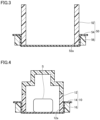
FIG. 3 is a cross-sectional view schematically showing a modification of the holder. -
FIG. 4 is a cross-sectional view schematically showing a modification of a sample container. - Some embodiments of the present invention will be described with reference to the attached drawings. Note that in the drawings referred to below, the same or corresponding member is denoted by the same reference symbol.
-
FIG. 1 is a diagram schematically showing a configuration of an X-ray analyzer according to one embodiment of the present invention. As shown inFIG. 1 , the X-ray analyzer 1 is provided with asample container 10, acasing 20, anX-ray irradiation source 30, adetector 40, and aholder 50. - The
sample container 10 is a container for accommodating a sample S. As shown inFIG. 2 , thesample container 10 includes acontainer body 12 and acontainer film 14. - The
container body 12 surrounds the sample S and has a shaped opened downward. Thecontainer body 12 is made of, for example, polypropylene (PP). - The
container film 14 closes the opening 12a (seeFIG. 2 ) of thecontainer body 12 and supports the sample S. In this embodiment, thecontainer film 14 is made of polypropylene. Thecontainer film 14 is welded to the lower end of thecontainer body 12. Thecontainer film 14 may be made of polyethylene terephthalate (PET) or the like. - The
casing 20 accommodates thesample container 10 and the like. Thecasing 20 is made of a metallic material. As shown inFIG. 1 , thecasing 20 includes ahousing 22, aplacement portion 24, and acover 26. - The
housing 22 is constituted by the lower portion of thecasing 20. Thehousing 22 accommodates theX-ray irradiation source 30 and thedetector 40. Thehousing 22 has a shape opened upward. - The
placement portion 24 is connected to the upper end of thehousing 22. Theplacement portion 24 is a portion on which thesample container 10 is placed. Theplacement portion 24 is provided with an opening 24h for passing the X-rays emitted from theX-ray irradiation source 30. The opening 24h is set to be smaller than the outer shape of thecontainer body 12. In other words, the outer shape of thecontainer body 12 is larger than the opening 24h. - The
cover 26 surrounds thesample container 10. The lower end of thecover 26 is connected to the outer edge of theplacement portion 24. - The
X-ray irradiation source 30 is accommodated in thehousing 22. TheX-ray irradiation source 30 irradiates the sample S placed in thesample container 10 with the X-rays from below theplacement portion 24. As an example of theX-ray irradiation source 30, an X-ray tube is exemplified. - The
detector 40 is accommodated in thehousing 22. Thedetector 40 detects the fluorescent X-rays generated from the sample S that received the X-rays emitted from theX-ray irradiation source 30 below theplacement portion 24. From the viewpoint of enhancing the analysis accuracy of the sample S, thedetector 40 is preferably arranged in the vicinity of the opening 24h. - The
holder 50 is placed on theplacement portion 24 and accommodates thesample container 10. Theholder 50 is configured to be removable from theplacement portion 24. As shown inFIG. 2 , theholder 50 includes anenclosure cylinder 52 and aholder film 54. - The
enclosure cylinder 52 has a profile larger than theopening 24h. Theenclosure cylinder 52 surrounds thesample container 10 and has a shape opened downward. In this embodiment, theenclosure cylinder 52 is formed in a cylindrical shape. Theenclosure cylinder 52 is made of, for example, polypropylene. The height of theenclosure cylinder 52 is greater than the height of thesample container 10. The position of theenclosure cylinder 52 with respect to theopening 24h is determined by a positioning mechanism (not shown). The innerperipheral surface 52S of theenclosure cylinder 52 may gradually decrease in diameter as it approaches theplacement portion 24. With this configuration, thesample container 10 is guided to a predetermined position when placing thesample container 10 in theenclosure cylinder 52 from above theenclosure cylinder 52. - The
holder film 54 closes theopening 52a (seeFIG. 2 ) of theenclosure cylinder 52. That is, two films (thecontainer film 14 and the holder film 54) are laminated above theopening 24h. Theholder film 54 is made of, for example, polypropylene. Theholder film 54 is welded to the lower end of theenclosure cylinder 52. The thickness of theholder film 54 is approximately the same as the thickness of thecontainer film 14. For example, the thickness of theholder film 54 is preferably set to 0.5 times or more and 2 times or less the thickness of thecontainer film 14. Note that theholder film 54 may be made of polyethylene terephthalate (PET) or the like. - As described above, in the X-ray analyzer 1 according to this embodiment, the
holder film 54 is further arranged below thecontainer film 14 supporting the sample S. Therefore, even in a case where thecontainer film 14 is, for example, damaged, dropping of the sample S from theplacement portion 24 is suppressed. Therefore, contamination or the like of thedetector 40 is suppressed. - It should be understood that the embodiments disclosed here are examples in all respects and are not restrictive. The scope of the present invention is indicated by claims rather than by the above-described descriptions of the embodiments and includes all modifications within the meanings and scopes equivalent to claims.
- For example, as shown in
FIG. 3 , theholder 50 may further include aclamping ring 56. In this embodiment, the outer shape of theholder film 54 is set to be larger than the outer shape of theenclosure cylinder 52. The clampingring 56 sandwiches the edge of theholder film 54 between the inner peripheral surface of the clampingring 56 and the outer peripheral surface of theenclosure cylinder 52. - Further, as shown in
FIG. 4 , thesample container 10 may further include aclamping ring 16. In this embodiment, the outer shape of thecontainer film 14 is set to be larger than the outer shape of thecontainer body 12. The clampingring 16 sandwiches the edge of thecontainer film 14 between the inner peripheral surface of the clampingring 16 and the outer peripheral surface of thecontainer body 12. - It will be understood by those skilled in the art that the plurality of exemplary embodiments described above is illustrative of the following aspects.
- An X-ray analyzer according to a first aspect of the present invention comprising:
- a sample container configured to accommodate a sample;
- a placement portion capable of placing the sample container thereon;
- an X-ray irradiation source configured to irradiate the sample in the sample container with X-rays from below the placement portion;
- a detector configured to detect fluorescent X-rays generated from the sample below the placement portion; and
- a holder placed on the placement portion, the holder being configured to accommodate the sample container,
- wherein the placement portion is provided with an opening for passing X-rays emitted from the X-ray irradiation source,
- wherein the sample container includes:
- a container body configured to surround the sample, the container body being formed in a shape having an opening opened downward; and
- a container film configured to close the opening of the container body and support the sample, and
- wherein the holder includes:
- an enclosure cylinder having an outer shape larger than the opening of the placement portion, the enclosure cylinder being configured to surround the sample container, the enclosure cylinder being formed in a shape having an opening opened downward; and
- a holder film closing the opening of the enclosure cylinder.
- In this X-ray analyzer, the holder film is further provided below the container film supporting the sample. Therefore, even in a case where the container film is damaged, dropping of the sample from the placement portion is suppressed.
- In the X-ray analyzer as recited in the above-described Item 1, it may be configured such that the holder film is welded to a lower end portion of the enclosure cylinder.
- In this aspect, the operation of attaching the holder film to the enclosure cylinder can be omitted.
- In the X-ray analyzer as recited in the above-described Item 1, it may be configured such that the holder further includes a clamping ring attached to a circumference of the enclosure cylinder, and the clamping ring sandwiches an edge of the holder film between an inner peripheral surface of the clamping ring and an outer peripheral surface of the enclosure cylinder.
- In this aspect, it is possible to attach a holder film made of a material that is difficult to weld to the enclosure cylinder (for example, a material that differs from the material constituting the enclosure cylinder) to the enclosure cylinder.
- In the X-ray analyzer as recited in any one of the above-described Items 1 to 3, it may be configured such that the holder is configured to be detachable from the placement portion.
- With this configuration, cleaning of the holder film, the replacement of the holder itself, etc., can be performed without causing damage to the X-ray irradiation source or the detector.
- In the X-ray analyzer as recited in any one of the above-described Items 1 to 4, it is preferable that an outer shape of the container body be larger than the opening of the placement portion.
- With this configuration, even in a case where the holder film is not attached to the enclosure cylinder, the sample can be analyzed by placing the sample container on the placement portion.
-
- 1:
- X-ray analyzer
- 10:
- Sample container
- 12:
- Container body
- 14:
- Container film
- 16:
- Clamping ring
- 20:
- Casing
- 22:
- Housing
- 24:
- Placement portion
- 24h:
- Opening
- 26:
- Cover
- 30:
- X-ray irradiation source
- 40:
- Detector
- 50:
- Holder
- 52:
- Enclosure cylinder
- 54:
- Holder film
- 56:
- Clamping ring
- S:
- Sample
Claims (5)
- An X-ray analyzer comprising:a sample container configured to accommodate a sample;a placement portion capable of placing the sample container thereon;an X-ray irradiation source configured to irradiate the sample in the sample container with X-rays from below the placement portion;a detector configured to detect fluorescent X-rays generated from the sample below the placement portion; anda holder placed on the placement portion, the holder being configured to accommodate the sample container,wherein the placement portion is provided with an opening for passing X-rays emitted from the X-ray irradiation source,wherein the sample container includes:a container body configured to surround the sample, the container body being formed in a shape having an opening opened downward; anda container film configured to close the opening of the container body and support the sample, andwherein the holder includes:an enclosure cylinder having an outer shape larger than the opening of the placement portion, the enclosure cylinder being configured to surround the sample container, the enclosure cylinder being formed in a shape having an opening opened downward; anda holder film closing the opening of the enclosure cylinder.
- The X-ray analyzer as recited in claim 1,
wherein the holder film is welded to a lower end portion of the enclosure cylinder. - The X-ray analyzer as recited in claim 1,wherein the holder further includes a clamping ring attached to a circumference of the enclosure cylinder, andwherein the clamping ring sandwiches an edge of the holder film between an inner peripheral surface of the clamping ring and an outer peripheral surface of the enclosure cylinder.
- The X-ray analyzer as recited in any one of claims 1 to 3,
wherein the holder is configured to be detachable from the placement portion. - The X-ray analyzer as recited in any one of claims 1 to 4,
wherein an outer shape of the container body is larger than the opening of the placement portion.
Applications Claiming Priority (1)
| Application Number | Priority Date | Filing Date | Title |
|---|---|---|---|
| PCT/JP2020/025763 WO2022003850A1 (en) | 2020-07-01 | 2020-07-01 | X-ray analysis apparatus |
Publications (3)
| Publication Number | Publication Date |
|---|---|
| EP4177600A1 true EP4177600A1 (en) | 2023-05-10 |
| EP4177600A4 EP4177600A4 (en) | 2024-03-06 |
| EP4177600B1 EP4177600B1 (en) | 2025-10-08 |
Family
ID=79315789
Family Applications (1)
| Application Number | Title | Priority Date | Filing Date |
|---|---|---|---|
| EP20943512.2A Active EP4177600B1 (en) | 2020-07-01 | 2020-07-01 | X-ray analyzer |
Country Status (6)
| Country | Link |
|---|---|
| US (1) | US20230236142A1 (en) |
| EP (1) | EP4177600B1 (en) |
| JP (2) | JPWO2022003850A1 (en) |
| CN (1) | CN115715365A (en) |
| TW (1) | TWI787821B (en) |
| WO (1) | WO2022003850A1 (en) |
Families Citing this family (1)
| Publication number | Priority date | Publication date | Assignee | Title |
|---|---|---|---|---|
| JP2026039749A (en) * | 2024-08-23 | 2026-03-09 | 日本電子株式会社 | Sample container, X-ray fluorescence analyzer, and measurement method |
Family Cites Families (15)
| Publication number | Priority date | Publication date | Assignee | Title |
|---|---|---|---|---|
| US4974244A (en) * | 1988-08-04 | 1990-11-27 | Angelo M. Torrisi | Sample positioning method and system for X-ray spectroscopic analysis |
| JP2838172B2 (en) * | 1991-05-03 | 1998-12-16 | 株式会社 堀場製作所 | X-ray fluorescence analyzer |
| JP2615279B2 (en) * | 1991-05-31 | 1997-05-28 | 理学電機工業株式会社 | Method for detecting contamination of window material in X-ray fluorescence analyzer |
| US5351281A (en) * | 1993-04-15 | 1994-09-27 | Angelo M. Torrisi | Handling support for X-ray spectroscopic analysis |
| JP3525188B2 (en) * | 2001-06-06 | 2004-05-10 | 理学電機工業株式会社 | X-ray fluorescence analyzer |
| JP3629539B2 (en) * | 2002-03-04 | 2005-03-16 | 理学電機工業株式会社 | X-ray fluorescence analyzer |
| WO2004088296A1 (en) * | 2003-03-28 | 2004-10-14 | Rigaku Industrial Corporation | Fluorescent x-ray analyzer |
| JP4398901B2 (en) * | 2005-05-10 | 2010-01-13 | 株式会社リガク | Sample holder for fluorescent X-ray analysis and fluorescent X-ray analysis method and apparatus using the same |
| JP5524521B2 (en) * | 2009-06-30 | 2014-06-18 | 株式会社堀場製作所 | X-ray fluorescence analyzer |
| JP5517506B2 (en) * | 2009-06-30 | 2014-06-11 | 株式会社堀場製作所 | X-ray fluorescence analyzer |
| JP2011089794A (en) * | 2009-10-20 | 2011-05-06 | Rigaku Corp | Sample holder for fluorescent x-ray analysis, and method and device of fluorescent x-ray analysis using the same |
| JP5907375B2 (en) | 2011-12-28 | 2016-04-26 | 株式会社テクノエックス | X-ray fluorescence analyzer and X-ray fluorescence analysis method |
| DE102014115383A1 (en) * | 2014-08-01 | 2016-02-04 | Helmut Fischer GmbH Institut für Elektronik und Messtechnik | Handheld device and mobile device for X-ray fluorescence analysis |
| JP6642372B2 (en) * | 2016-10-14 | 2020-02-05 | 株式会社島津製作所 | X-ray analyzer |
| CN108956672B (en) * | 2018-05-15 | 2021-12-17 | 江苏天瑞仪器股份有限公司 | Detection method for detecting heavy metal by using special sample cup of food rapid detector |
-
2020
- 2020-07-01 WO PCT/JP2020/025763 patent/WO2022003850A1/en not_active Ceased
- 2020-07-01 JP JP2022532907A patent/JPWO2022003850A1/ja active Pending
- 2020-07-01 US US18/013,198 patent/US20230236142A1/en not_active Abandoned
- 2020-07-01 CN CN202080102470.2A patent/CN115715365A/en active Pending
- 2020-07-01 EP EP20943512.2A patent/EP4177600B1/en active Active
-
2021
- 2021-05-17 TW TW110117615A patent/TWI787821B/en active
-
2024
- 2024-06-13 JP JP2024095686A patent/JP7679908B2/en active Active
Also Published As
| Publication number | Publication date |
|---|---|
| US20230236142A1 (en) | 2023-07-27 |
| JP2024107407A (en) | 2024-08-08 |
| JP7679908B2 (en) | 2025-05-20 |
| CN115715365A (en) | 2023-02-24 |
| EP4177600A4 (en) | 2024-03-06 |
| TW202202834A (en) | 2022-01-16 |
| WO2022003850A1 (en) | 2022-01-06 |
| TWI787821B (en) | 2022-12-21 |
| JPWO2022003850A1 (en) | 2022-01-06 |
| EP4177600B1 (en) | 2025-10-08 |
Similar Documents
| Publication | Publication Date | Title |
|---|---|---|
| CN110678739B (en) | Biological sample analysis device | |
| US9810649B2 (en) | X-ray fluorescence analyzer | |
| JP2026048652A5 (en) | ||
| CN101025401B (en) | Fluorescent X-ray analysis apparatus | |
| EP3404396B1 (en) | System for processing a dried fluid sample substrate, and method therefor | |
| US9182362B2 (en) | Apparatus for protecting a radiation window | |
| EP4177600B1 (en) | X-ray analyzer | |
| TW202022364A (en) | X-ray analysis device | |
| CN107957430B (en) | X-ray analysis apparatus | |
| US12596083B2 (en) | Automated analyzer | |
| JP5010725B2 (en) | Analysis equipment | |
| JP5782154B2 (en) | X-ray fluorescence analyzer | |
| JP5524521B2 (en) | X-ray fluorescence analyzer | |
| JP7605021B2 (en) | X-ray analysis equipment | |
| JPWO2022003850A5 (en) | ||
| JP2014038035A (en) | X-ray detecting apparatus, and sample mounting body | |
| JP7649591B1 (en) | X-ray fluorescence analyzer | |
| JP5448347B2 (en) | Explosives inspection device | |
| JP4771985B2 (en) | Radiation inspection equipment | |
| JP2006518534A (en) | Sample enclosure for a scanning electron microscope and its use | |
| JP2013160615A (en) | Weight measuring method and weight measuring apparatus for radiopharmaceutical, and transportation container | |
| US20260140075A1 (en) | X-ray fluorescence spectrometer | |
| JP2000162161A (en) | X-ray fluorescence analyzer | |
| JP2013108874A (en) | Automatic analyzer | |
| JP2015158457A (en) | Fluorescence x-ray analysis device |
Legal Events
| Date | Code | Title | Description |
|---|---|---|---|
| STAA | Information on the status of an ep patent application or granted ep patent |
Free format text: STATUS: THE INTERNATIONAL PUBLICATION HAS BEEN MADE |
|
| PUAI | Public reference made under article 153(3) epc to a published international application that has entered the european phase |
Free format text: ORIGINAL CODE: 0009012 |
|
| STAA | Information on the status of an ep patent application or granted ep patent |
Free format text: STATUS: REQUEST FOR EXAMINATION WAS MADE |
|
| 17P | Request for examination filed |
Effective date: 20230126 |
|
| AK | Designated contracting states |
Kind code of ref document: A1 Designated state(s): AL AT BE BG CH CY CZ DE DK EE ES FI FR GB GR HR HU IE IS IT LI LT LU LV MC MK MT NL NO PL PT RO RS SE SI SK SM TR |
|
| DAV | Request for validation of the european patent (deleted) | ||
| DAX | Request for extension of the european patent (deleted) | ||
| A4 | Supplementary search report drawn up and despatched |
Effective date: 20240201 |
|
| RIC1 | Information provided on ipc code assigned before grant |
Ipc: G01N 23/2204 20180101ALI20240126BHEP Ipc: G01N 23/223 20060101AFI20240126BHEP |
|
| GRAP | Despatch of communication of intention to grant a patent |
Free format text: ORIGINAL CODE: EPIDOSNIGR1 |
|
| STAA | Information on the status of an ep patent application or granted ep patent |
Free format text: STATUS: GRANT OF PATENT IS INTENDED |
|
| INTG | Intention to grant announced |
Effective date: 20250430 |
|
| GRAS | Grant fee paid |
Free format text: ORIGINAL CODE: EPIDOSNIGR3 |
|
| GRAA | (expected) grant |
Free format text: ORIGINAL CODE: 0009210 |
|
| STAA | Information on the status of an ep patent application or granted ep patent |
Free format text: STATUS: THE PATENT HAS BEEN GRANTED |
|
| AK | Designated contracting states |
Kind code of ref document: B1 Designated state(s): AL AT BE BG CH CY CZ DE DK EE ES FI FR GB GR HR HU IE IS IT LI LT LU LV MC MK MT NL NO PL PT RO RS SE SI SK SM TR |
|
| REG | Reference to a national code |
Ref country code: GB Ref legal event code: FG4D Ref country code: CH Ref legal event code: F10 Free format text: ST27 STATUS EVENT CODE: U-0-0-F10-F00 (AS PROVIDED BY THE NATIONAL OFFICE) Effective date: 20251008 |
|
| REG | Reference to a national code |
Ref country code: DE Ref legal event code: R096 Ref document number: 602020060335 Country of ref document: DE |
|
| REG | Reference to a national code |
Ref country code: IE Ref legal event code: FG4D |
|
| REG | Reference to a national code |
Ref country code: NL Ref legal event code: MP Effective date: 20251008 |
|
| REG | Reference to a national code |
Ref country code: AT Ref legal event code: MK05 Ref document number: 1845201 Country of ref document: AT Kind code of ref document: T Effective date: 20251008 |
|
| PG25 | Lapsed in a contracting state [announced via postgrant information from national office to epo] |
Ref country code: NL Free format text: LAPSE BECAUSE OF FAILURE TO SUBMIT A TRANSLATION OF THE DESCRIPTION OR TO PAY THE FEE WITHIN THE PRESCRIBED TIME-LIMIT Effective date: 20251008 |
|
| PG25 | Lapsed in a contracting state [announced via postgrant information from national office to epo] |
Ref country code: ES Free format text: LAPSE BECAUSE OF FAILURE TO SUBMIT A TRANSLATION OF THE DESCRIPTION OR TO PAY THE FEE WITHIN THE PRESCRIBED TIME-LIMIT Effective date: 20251008 |
|
| REG | Reference to a national code |
Ref country code: LT Ref legal event code: MG9D |
|
| PG25 | Lapsed in a contracting state [announced via postgrant information from national office to epo] |
Ref country code: NO Free format text: LAPSE BECAUSE OF FAILURE TO SUBMIT A TRANSLATION OF THE DESCRIPTION OR TO PAY THE FEE WITHIN THE PRESCRIBED TIME-LIMIT Effective date: 20260108 |
|
| PG25 | Lapsed in a contracting state [announced via postgrant information from national office to epo] |
Ref country code: HR Free format text: LAPSE BECAUSE OF FAILURE TO SUBMIT A TRANSLATION OF THE DESCRIPTION OR TO PAY THE FEE WITHIN THE PRESCRIBED TIME-LIMIT Effective date: 20251008 Ref country code: FI Free format text: LAPSE BECAUSE OF FAILURE TO SUBMIT A TRANSLATION OF THE DESCRIPTION OR TO PAY THE FEE WITHIN THE PRESCRIBED TIME-LIMIT Effective date: 20251008 Ref country code: AT Free format text: LAPSE BECAUSE OF FAILURE TO SUBMIT A TRANSLATION OF THE DESCRIPTION OR TO PAY THE FEE WITHIN THE PRESCRIBED TIME-LIMIT Effective date: 20251008 |
|
| PG25 | Lapsed in a contracting state [announced via postgrant information from national office to epo] |
Ref country code: RS Free format text: LAPSE BECAUSE OF FAILURE TO SUBMIT A TRANSLATION OF THE DESCRIPTION OR TO PAY THE FEE WITHIN THE PRESCRIBED TIME-LIMIT Effective date: 20260108 |
|
| PG25 | Lapsed in a contracting state [announced via postgrant information from national office to epo] |
Ref country code: IS Free format text: LAPSE BECAUSE OF FAILURE TO SUBMIT A TRANSLATION OF THE DESCRIPTION OR TO PAY THE FEE WITHIN THE PRESCRIBED TIME-LIMIT Effective date: 20260208 |
|
| PG25 | Lapsed in a contracting state [announced via postgrant information from national office to epo] |
Ref country code: PT Free format text: LAPSE BECAUSE OF FAILURE TO SUBMIT A TRANSLATION OF THE DESCRIPTION OR TO PAY THE FEE WITHIN THE PRESCRIBED TIME-LIMIT Effective date: 20260209 |
|
| PG25 | Lapsed in a contracting state [announced via postgrant information from national office to epo] |
Ref country code: PL Free format text: LAPSE BECAUSE OF FAILURE TO SUBMIT A TRANSLATION OF THE DESCRIPTION OR TO PAY THE FEE WITHIN THE PRESCRIBED TIME-LIMIT Effective date: 20251008 |
|
| PG25 | Lapsed in a contracting state [announced via postgrant information from national office to epo] |
Ref country code: LV Free format text: LAPSE BECAUSE OF FAILURE TO SUBMIT A TRANSLATION OF THE DESCRIPTION OR TO PAY THE FEE WITHIN THE PRESCRIBED TIME-LIMIT Effective date: 20251008 |
|
| PG25 | Lapsed in a contracting state [announced via postgrant information from national office to epo] |
Ref country code: BG Free format text: LAPSE BECAUSE OF FAILURE TO SUBMIT A TRANSLATION OF THE DESCRIPTION OR TO PAY THE FEE WITHIN THE PRESCRIBED TIME-LIMIT Effective date: 20251008 |