JP2006518534A - Sample enclosure for a scanning electron microscope and its use - Google Patents
Sample enclosure for a scanning electron microscope and its use Download PDFInfo
- Publication number
- JP2006518534A JP2006518534A JP2005515862A JP2005515862A JP2006518534A JP 2006518534 A JP2006518534 A JP 2006518534A JP 2005515862 A JP2005515862 A JP 2005515862A JP 2005515862 A JP2005515862 A JP 2005515862A JP 2006518534 A JP2006518534 A JP 2006518534A
- Authority
- JP
- Japan
- Prior art keywords
- sample
- enclosure
- sem
- membrane
- sample container
- Prior art date
- Legal status (The legal status is an assumption and is not a legal conclusion. Google has not performed a legal analysis and makes no representation as to the accuracy of the status listed.)
- Pending
Links
Images


Abstract
【解決手段】 SEMサンプル容器は、サンプルエンクロージャ(100,102)であって、電子ビーム透過性で流体不透過性の膜(132)と、該膜に密封されて該膜と共に前記サンプルエンクロージャを形成する、周囲エンクロージャと、を備える、サンプルエンクロージャと、サンプルエンクロージャとの係合を密封するための迅速接続式アタッチメント(152)機能を有する、サンプルエンクロージャの閉鎖部と、を備える。An SEM sample container is a sample enclosure (100, 102) comprising an electron beam permeable and fluid impermeable membrane (132) and sealed to the membrane to form the sample enclosure together with the membrane. A sample enclosure comprising a surrounding enclosure, and a closure of the sample enclosure having a quick connect attachment (152) function for sealing engagement with the sample enclosure.
Description
本発明は、概して、サンプルを含む流体のSEM検査に係り、より詳しくは、サンプル容器及び検査システム、並びに、その利用方法に関する。 The present invention relates generally to SEM inspection of fluids containing samples, and more particularly to sample containers and inspection systems and methods of use thereof.
次の米国特許文献が当該技術分野の現在の状態を表していると考えられる。
本発明は、サンプルを含む流体のSEM検査を可能とするための装置、システム及び方法を提供することを目的としている。
以上により、本発明の好ましい実施例によれば、SEM互換性サンプル容器は、サンプルエンクロージャであって、電子ビーム透過性で流体不透過性の膜と、該膜に密封されて該膜と共に前記サンプルエンクロージャを形成する、周囲エンクロージャと、を備える、前記サンプルエンクロージャと、サンプルエンクロージャとの係合を密封するための迅速接続式アタッチメント機能を有する、サンプルエンクロージャの閉鎖部と、を備えて提供される。好ましくは、迅速接続式アタッチメントの機能は、バヨネット式の接続機能を備える。更には、周囲エンクロージャは、少なくとも部分的に導電性である。代替例として又は上記に加えて、SEM互換性サンプル容器は、サンプルエンクロージャと連係された圧力リリーフダイヤフラムを更に備える。
It is an object of the present invention to provide an apparatus, system and method for enabling SEM inspection of fluid containing a sample.
Thus, according to a preferred embodiment of the present invention, the SEM compatible sample container is a sample enclosure, which is an electron beam permeable and fluid impermeable membrane, sealed to the membrane and the sample together with the membrane. A sample enclosure comprising a surrounding enclosure forming an enclosure, and a closure of the sample enclosure having a quick connect attachment function for sealing engagement with the sample enclosure. Preferably, the function of the quick connection type attachment includes a bayonet type connection function. Furthermore, the surrounding enclosure is at least partially conductive. As an alternative or in addition, the SEM compatible sample container further comprises a pressure relief diaphragm associated with the sample enclosure.
本発明の別の好ましい実施例によれば、SEM互換性サンプル容器は、膜に連係された少なくとも1つの基準配位インジケータを更に備えて提供される。好ましくは、SEM互換性サンプル容器は、膜を支持し、且つ、基準配位インジケータを有する、少なくとも1つの膜支持格子を更に備える。加えて、該膜は、ポリイミド、ポリアミド、ポリアミド−イミド、ポリエチレン、ポリピロール、「パーロディオン」、「コロディオン」、「カプトン」、「フォームバー」、「ビニレック」、「バットバー」、「ピオロフォルム」、「パリレーネ」、二酸化シリコン、一酸化シリコン、及び、カーボンからなるグループから選択された材料から形成されている。代替例として又は加えて、サンプルエンクロージャは、予め組み立てられ、サンプルを含む液体を受け取るように準備され、該準備に続いて、サンプルエンクロージャの閉鎖部を、迅速接続式アタッチメント機能を用いて容易に密封連結することができる。 According to another preferred embodiment of the present invention, a SEM compatible sample container is provided further comprising at least one reference coordination indicator associated with the membrane. Preferably, the SEM compatible sample container further comprises at least one membrane support grid that supports the membrane and has a reference coordination indicator. In addition, the membrane is composed of polyimide, polyamide, polyamide-imide, polyethylene, polypyrrole, “Perrodion”, “Colodion”, “Kapton”, “Form Bar”, “Vinyleck”, “Bat Bar”, “Pioroform”, It is formed from a material selected from the group consisting of “Parilene”, silicon dioxide, silicon monoxide, and carbon. As an alternative or in addition, the sample enclosure is pre-assembled and prepared to receive the liquid containing the sample, and following the preparation, the closure of the sample enclosure is easily sealed using the quick connect attachment feature. Can be linked.
本発明の別の好ましい実施例によれば、SEM互換性サンプル容器は、液体サンプルエンクロージャを備え、該液体サンプルエンクロージャは、電子ビーム透過性で流体不透過性の膜と、該膜に密封されて該膜と共に前記液体サンプルエンクロージャを形成する、周囲エンクロージャと、を備え、該サンプルエンクロージャは、50KeVより小さいエネルギーレベルを有する電子によっては透過可能ではない深さで液体を含むことができる。 According to another preferred embodiment of the present invention, the SEM compatible sample container comprises a liquid sample enclosure, the liquid sample enclosure being sealed to the membrane with an electron beam permeable and fluid impermeable membrane. An ambient enclosure that forms the liquid sample enclosure with the membrane, the sample enclosure being capable of containing liquid at a depth that is not permeable by electrons having an energy level of less than 50 KeV.
本発明の更に別の好ましい実施例によれば、SEM互換性サンプル容器は、サンプル皿部であって、電子ビーム透過性で流体不透過性の膜と、該膜に密封されて該膜と共に前記サンプル皿部を形成する、周囲エンクロージャと、を備える、前記サンプル皿部と、前記サンプル皿部の周りに配列され、該皿部の内部と共に、前記膜を電子が通過するためのアパーチャを形成する、外側エンクロージャと、を備えて提供される。 According to yet another preferred embodiment of the present invention, the SEM compatible sample container is a sample pan, an electron beam permeable fluid impermeable membrane, and sealed with the membrane together with the membrane. A sample enclosure comprising a surrounding enclosure forming a sample dish; and arranged around the sample dish to form an aperture for electrons to pass through the membrane with the interior of the dish And an outer enclosure.
本発明のなお別の好ましい実施例によれば、SEM互換性サンプル容器は、電子が通過するためのアパーチャを形成するエンクロージャと、エンクロージャの内部に配置され、電子ビーム透過性で流体不透過性の膜を備える、サンプル皿部と、を備え、該アパーチャは、膜を通してエンクロージャの内部と電子を連通させるように膜に対して配置されている。好ましくは、サンプル皿部は、エンクロージャと共に膜によって形成されている。更には、前記サンプル皿部は、エンクロージャ内部に配置された別個の皿壁と共に膜によって形成されている。代替例として又はこれに加えて、別個の皿壁は、膜に密封されている。 In accordance with yet another preferred embodiment of the present invention, an SEM compatible sample container includes an enclosure that forms an aperture for the passage of electrons and an electron beam transmissive and fluid impervious disposed within the enclosure. A sample pan with a membrane, the aperture being disposed relative to the membrane to communicate electrons with the interior of the enclosure through the membrane. Preferably, the sample pan is formed by a membrane together with the enclosure. Furthermore, the sample pan is formed by a membrane together with a separate pan wall arranged inside the enclosure. As an alternative or in addition, the separate dish wall is sealed to the membrane.
本発明の更に好ましい実施例によれば、SEM互換性サンプル容器は、アパーチャを形成するサンプル皿部アッセンブリであって、該アパーチャは該アパーチャを通して電子を連通させ、前記サンプル皿部アッセンブリは、少なくとも部分的にサンプルエンクロージャを形成する電子ビーム透過性で流体不透過性の膜を備える、前記サンプル皿部アッセンブリと、サンプルと係合した状態で直線的な非回転運動をし、これにより前記膜に隣接して前記サンプルを位置決めするように構成された、サンプルポジショナーと、エンクロージャとの係合を密封するための迅速接続式アタッチメント機能を有する閉鎖部と、を備え、
アパーチャは、サンプルが膜に隣接した状態で、該アパーチャを通して電子を連通させるように膜に対して配置され、該アパーチャは膜を貫通する。好ましくは、サンプルポジショナーは、可撓性支持要素を備える。加えて、可撓性支持要素は、細胞支持要素を備える。
According to a further preferred embodiment of the present invention, the SEM compatible sample container is a sample pan assembly forming an aperture, the aperture communicating electrons through the aperture, the sample pan assembly being at least partially A sample non-rotating motion in engagement with the sample and the sample pan assembly comprising an electron beam transmissive and fluid impermeable membrane that forms a sample enclosure in general, thereby adjacent to the membrane A sample positioner configured to position the sample and a closure having a quick connect attachment function for sealing engagement with the enclosure;
The aperture is positioned relative to the membrane such that electrons are in communication therethrough with the sample adjacent to the membrane, the aperture penetrating the membrane. Preferably, the sample positioner comprises a flexible support element. In addition, the flexible support element comprises a cell support element.
本発明の別の好ましい実施例によれば、可撓性支持要素は、細胞成長要素を備える。好ましくは、可撓性支持要素は、流体フィルター要素を備える。加えて、可撓性支持要素は、膜を備える。 According to another preferred embodiment of the invention, the flexible support element comprises a cell growth element. Preferably, the flexible support element comprises a fluid filter element. In addition, the flexible support element comprises a membrane.
本発明の更に別の好ましい実施例によれば、可撓性支持要素は、弾性膜支持部を備える。好ましくは、可撓性支持要素は、少なくとも部分的に液体が透過可能である。更に加えて、サンプルポジショナーは、スプリングを備える。 According to yet another preferred embodiment of the invention, the flexible support element comprises an elastic membrane support. Preferably, the flexible support element is at least partially permeable to liquid. In addition, the sample positioner includes a spring.
本発明の更なる好ましい実施例によれば、SEM互換性サンプル容器は、アパーチャを形成するサンプル皿部アッセンブリであって、該アパーチャは該アパーチャを通して電子を連通させ、サンプル皿部アッセンブリは、少なくとも部分的にサンプルエンクロージャを形成する電子ビーム透過性で流体不透過性の膜を備える、前記サンプル皿部アッセンブリと、該サンプル皿部アッセンブリと連係した圧力リリーフダイヤフラムと、を備える。 In accordance with a further preferred embodiment of the present invention, the SEM compatible sample container is a sample pan assembly that forms an aperture, the aperture communicating electrons through the aperture, the sample pan assembly being at least a portion of the sample pan assembly. The sample pan assembly comprising an electron beam transmissive and fluid impermeable membrane that forms a sample enclosure, and a pressure relief diaphragm associated with the sample pan assembly.
本発明のなお更なる好ましい実施例によれば、SEM互換性サンプル容器は、アパーチャを形成するサンプル皿部アッセンブリであって、該アパーチャは該アパーチャを通して電子を連通させ、サンプル皿部アッセンブリは、少なくとも部分的にサンプルエンクロージャを形成する電子ビーム透過性で流体不透過性の膜を備える、前記サンプル皿部アッセンブリと、膜に連係された少なくとも1つの基準配位インジケータと、を備える。 According to a still further preferred embodiment of the present invention, the SEM compatible sample container is a sample pan assembly that forms an aperture, the aperture communicating electrons through the aperture, the sample pan assembly being at least The sample pan assembly comprising an electron beam transmissive and fluid impermeable membrane that partially forms a sample enclosure, and at least one reference configuration indicator associated with the membrane.
本発明のなお更なる好ましい実施例によれば、SEM互換性を持つ顕微鏡検査前の多重サンプル容器システムは、複数のSEM互換性サンプル容器と、複数のSEM互換性サンプル容器を支持するための支持部と、を備える。好ましくは、支持部は、複数のSEM互換性サンプル容器内の膜の少なくとも1つの下方に配置された光透過部を備え、これによって複数のSEM互換性サンプル容器が前記支持部で支持されている間に該SEM互換性サンプル容器の少なくとも1つ内のサンプルに関して光学顕微鏡による検査を実行することができる。更に加えて、SEM互換性を持つ顕微鏡検査前の多重サンプル容器システムは、支持部と、該支持部に支持された複数のSEM互換性サンプル容器とを覆うように配置されたカバーを更に備える。 In accordance with yet a further preferred embodiment of the present invention, a SEM-compatible pre-microscope multiple sample container system comprises a plurality of SEM compatible sample containers and a support for supporting a plurality of SEM compatible sample containers. A section. Preferably, the support part includes a light transmission part disposed below at least one of the membranes in the plurality of SEM compatible sample containers, whereby the plurality of SEM compatible sample containers are supported by the support part. In between, an optical microscope inspection can be performed on the sample in at least one of the SEM compatible sample containers. In addition, the SEM-compatible multi-sample container system prior to microscopic examination further includes a cover arranged to cover the support and a plurality of SEM-compatible sample containers supported by the support.
本発明の別の好ましい実施例によれば、支持部は、複数のSEM互換性サンプル容器が支持部に支持されている間に該複数のSEM互換性サンプル容器内でサンプルの湿度を維持するのに有用である液体を保持するための少なくとも1つの液体リザーバーを備える。好ましくは、SEM互換性多重サンプル容器には、吸引装置とピペットとが設けられている。更に加えて、吸引装置は、支持部とのその作動的な係合時に、複数のSEM互換性サンプル容器の膜とのその物理的係合が防止されるように構成されている。 According to another preferred embodiment of the invention, the support maintains the humidity of the sample within the plurality of SEM compatible sample containers while the plurality of SEM compatible sample containers are supported by the support. At least one liquid reservoir for holding a liquid that is useful for. Preferably, the SEM compatible multiple sample container is provided with a suction device and a pipette. In addition, the aspiration device is configured to prevent its physical engagement with the membranes of a plurality of SEM compatible sample containers upon its operative engagement with the support.
本発明の更に別の好ましい実施例によれば、ピペットには、該ピペットと膜との意図しない係合を防止するためカラー要素が設けられている。好ましくは、顕微鏡検査前の多重サンプル容器は、従来の細胞生物学の設備と互換性があるように寸法が定められている。更に加えて、支持部は、複数のSEM互換性サンプル容器の個々の容器を互いに対して取り外し可能に保持するための保持機能を備える。 According to yet another preferred embodiment of the invention, the pipette is provided with a collar element to prevent unintentional engagement between the pipette and the membrane. Preferably, the multiple sample container prior to microscopy is dimensioned to be compatible with conventional cell biology equipment. In addition, the support includes a holding function for removably holding individual containers of the plurality of SEM compatible sample containers relative to each other.
本発明の更に別の好ましい実施例によれば、SEMシステムは、SEMと、アパーチャを形成するサンプル皿部アッセンブリであって、該アパーチャは該アパーチャを通して電子を連通させ、前記サンプル皿部アッセンブリは、少なくとも部分的にサンプルエンクロージャを形成する電子ビーム透過性で流体不透過性の膜を備える、前記サンプル皿部アッセンブリと、サンプルエンクロージャ内に配置されたサンプル含有液体からSEM検査の間にX線を受け取るように配置されたX線検出器と、を備える。好ましくは、SEMシステムは、サンプルエンクロージャとの係合を密封するための迅速接続式アタッチメント機能を有する、サンプルエンクロージャ閉鎖部を更に備える。更に加えて、迅速接続式アタッチメントの機能は、バヨネット式の接続機能を備える。 According to yet another preferred embodiment of the present invention, the SEM system is a sample pan assembly that forms an aperture with the SEM, the aperture communicating electrons through the aperture, the sample pan assembly comprising: X-rays are received between the sample pan assembly comprising an electron beam transmissive and fluid impermeable membrane that at least partially forms a sample enclosure and a sample-containing liquid disposed in the sample enclosure during SEM inspection And an X-ray detector arranged as described above. Preferably, the SEM system further comprises a sample enclosure closure having a quick connect attachment function for sealing engagement with the sample enclosure. In addition, the quick connect attachment function includes a bayonet connection function.
本発明の別の好ましい実施例によれば、サンプルエンクロージャは、少なくとも部分的に導電性である。好ましくは、SEMシステムは、サンプルエンクロージャと連係した圧力リリーフダイヤフラムを更に備える。更に加えて、SEMシステムは、膜に連係された少なくとも1つの基準配位インジケータを更に備える。 According to another preferred embodiment of the present invention, the sample enclosure is at least partially conductive. Preferably, the SEM system further comprises a pressure relief diaphragm associated with the sample enclosure. In addition, the SEM system further comprises at least one reference coordination indicator associated with the membrane.
本発明の更に別の好ましい実施例によれば、SEMシステムは、膜を支持し、且つ、基準配位インジケータ機能を有する、少なくとも1つの膜支持格子を更に備える。好ましくは、前記膜は、ポリイミド、ポリアミド、ポリアミド−イミド、ポリエチレン、ポリピロール、「パーロディオン」、「コロディオン」、「カプトン」、「フォームバー」、「ビニレック」、「バットバー」、「ピオロフォルム」、「パリレーネ」、二酸化シリコン、一酸化シリコン、及び、カーボンからなるグループから選択された材料から形成されている。更に加えて、サンプルエンクロージャは、予め組み立てられ、サンプルを含む液体を受け取るように準備され、該準備に続いて、前記サンプルエンクロージャ閉鎖部を、前記迅速接続式アタッチメント機能を用いて容易に密封連結することができる。 According to yet another preferred embodiment of the present invention, the SEM system further comprises at least one membrane support grid that supports the membrane and has a reference coordination indicator function. Preferably, the membrane is polyimide, polyamide, polyamide-imide, polyethylene, polypyrrole, “Perrodion”, “Colodion”, “Kapton”, “Form Bar”, “Vinyleck”, “Bat Bar”, “Pioform”, It is formed from a material selected from the group consisting of “Parilene”, silicon dioxide, silicon monoxide, and carbon. In addition, the sample enclosure is pre-assembled and prepared to receive the liquid containing the sample, and following the preparation, the sample enclosure closure is easily hermetically coupled using the quick connect attachment feature. be able to.
本発明の更に別の好ましい実施例によれば、SEMシステムは、SEMと、サンプルエンクロージャを有するSEM互換性サンプル容器であって、該サンプルエンクロージャは、電子ビーム透過性で流体不透過性の膜と、該膜に密封されて該膜と共に液体サンプルエンクロージャを形成する、周囲エンクロージャと、を備える、前記SEM互換性サンプル容器と、サンプルエンクロージャとの係合を密封するための迅速接続式アタッチメント機能を有する、サンプルエンクロージャの閉鎖部と、を備える。好ましくは、迅速接続式アタッチメントの機能は、バヨネット式の接続機能を備える。加えて、周囲エンクロージャは、少なくとも部分的に導電性である。 In accordance with yet another preferred embodiment of the present invention, the SEM system is a SEM and a SEM compatible sample container having a sample enclosure, the sample enclosure comprising an electron beam transmissive and fluid impermeable membrane. A perimeter enclosure that forms a liquid sample enclosure with the membrane and has a quick connect attachment function for sealing engagement between the SEM compatible sample container and the sample enclosure A closure of the sample enclosure. Preferably, the function of the quick connection type attachment includes a bayonet type connection function. In addition, the surrounding enclosure is at least partially conductive.
本発明のなお更に別の好ましい実施例によれば、SEMシステムは、サンプルエンクロージャと連係した圧力リリーフダイヤフラムを更に備える。好ましくは。SEMシステムは、膜に連係された少なくとも1つの基準配位インジケータを更に備える。更に加えて、SEMシステムは、膜を支持し、且つ、基準配位インジケータ機能を有する、少なくとも1つの膜支持格子を更に備える。 According to yet another preferred embodiment of the present invention, the SEM system further comprises a pressure relief diaphragm associated with the sample enclosure. Preferably. The SEM system further comprises at least one reference coordination indicator associated with the membrane. In addition, the SEM system further comprises at least one membrane support grid that supports the membrane and has a reference coordination indicator function.
本発明の更に別の好ましい実施例によれば、前記膜は、ポリイミド、ポリアミド、ポリアミド−イミド、ポリエチレン、ポリピロール、「パーロディオン」、「コロディオン」、「カプトン」、「フォームバー」、「ビニレック」、「バットバー」、「ピオロフォルム」、「パリレーネ」、二酸化シリコン、一酸化シリコン、及び、カーボンからなるグループから選択された材料から形成されている。好ましくは、サンプルエンクロージャは、予め組み立てられ、サンプルを含む液体を受け取るように準備され、該準備に続いて、前記サンプルエンクロージャ閉鎖部を、前記迅速接続式アタッチメント機能を用いて容易に密封連結することができる。 According to still another preferred embodiment of the present invention, the membrane comprises polyimide, polyamide, polyamide-imide, polyethylene, polypyrrole, “Perrodion”, “Colodion”, “Kapton”, “Form Bar”, “Vinyleck”. ”,“ Batbar ”,“ Pioloform ”,“ Parilene ”, silicon dioxide, silicon monoxide, and a material selected from the group consisting of carbon. Preferably, the sample enclosure is pre-assembled and prepared to receive the liquid containing the sample, and following the preparation, the sample enclosure closure is easily hermetically coupled using the quick connect attachment feature. Can do.
本発明の更に別の好ましい実施例によれば、走査型電子顕微鏡による検査を実行するための方法は、サンプルエンクロージャ内にサンプルを配置する工程であって、該サンプルエンクロージャは、電子ビーム透過性で流体不透過性の膜と、該膜に密封されて該膜と共に前記サンプルエンクロージャを形成する、周囲エンクロージャと、前記サンプルエンクロージャとの係合を密封するための迅速接続式アタッチメント機能を有する、サンプルエンクロージャの閉鎖部と、を備える、前記工程と、サンプルエンクロージャをサンプルエンクロージャ閉鎖部で密封する工程と、サンプルエンクロージャを電子ビーム内に配置する工程と、電子ビームとサンプルとの相互作用の結果を分析する工程と、を備える。好ましくは、走査型電子顕微鏡による検査を実行するための方法は、密封工程の前に、サンプルエンクロージャから液体を除去する工程を更に備える。更に加えて、走査型電子顕微鏡による検査を実行するための方法は、密封工程の前に、サンプルエンクロージャに液体を追加する工程を更に備える。 According to yet another preferred embodiment of the present invention, a method for performing a scanning electron microscope examination is the step of placing a sample in a sample enclosure, the sample enclosure being electron beam transmissive. A sample enclosure having a fluid impermeable membrane, a surrounding enclosure that is sealed to the membrane to form the sample enclosure together with the membrane, and a quick connect attachment function for sealing engagement of the sample enclosure A step of sealing the sample enclosure with the sample enclosure closure, placing the sample enclosure in the electron beam, and analyzing the results of the interaction of the electron beam and the sample A process. Preferably, the method for performing a scanning electron microscope inspection further comprises removing liquid from the sample enclosure prior to the sealing step. In addition, the method for performing a scanning electron microscope inspection further comprises adding a liquid to the sample enclosure prior to the sealing step.
本発明の更に別の好ましい実施例によれば、走査型電子顕微鏡による検査を実行するための方法は、サンプルエンクロージャ内での前記サンプルの培養工程を備える。好ましくは、サンプルと電子ビームとの相互作用の前記結果の分析は、X線の検出と、紫外線から赤外線の範囲における光の検出と、後方散乱電子の検出と、2次電子の検出と、のうち少なくとも1つにより実施される。 According to yet another preferred embodiment of the present invention, a method for performing a scanning electron microscope examination comprises the step of culturing the sample in a sample enclosure. Preferably, the analysis of the result of the interaction between the sample and the electron beam comprises X-ray detection, detection of light in the ultraviolet to infrared range, detection of backscattered electrons, and detection of secondary electrons. Implemented by at least one of them.
本発明の更に別の好ましい実施例によれば、走査型電子顕微鏡による検査を実行するための方法は、サンプルエンクロージャ内にサンプルを配置する工程であって、該サンプルエンクロージャは、電子ビーム透過性で流体不透過性の膜と、該膜に密封されて該膜と共に前記サンプルエンクロージャを形成する、周囲エンクロージャと、サンプルエンクロージャとの係合を密封するための迅速接続式アタッチメント機能を有する、サンプルエンクロージャの閉鎖部と、を備える、前記工程と、サンプルを膜に隣接して位置決めするように配列されたサンプルポジショナーを配置し、サンプルエンクロージャの閉鎖部を用いてサンプルエンクロージャを密封し、サンプルエンクロージャを電子ビーム内に配置し、電子ビームとサンプルとの相互作用の結果を分析する、各工程を備える。好ましくは、走査型電子顕微鏡による検査を実行するための方法は、密封工程の前にサンプルエンクロージャから液体を除去する工程を更に備える。更に加えて、走査型電子顕微鏡による検査を実行するための方法は、密封工程の前にサンプルエンクロージャに液体を追加する工程を更に備える。 According to yet another preferred embodiment of the present invention, a method for performing a scanning electron microscope examination is the step of placing a sample in a sample enclosure, the sample enclosure being electron beam transmissive. A sample enclosure having a fluid impermeable membrane and a quick connect attachment function for sealing the engagement between the surrounding enclosure and the sample enclosure that is sealed to the membrane to form the sample enclosure. A closure, and placing the sample positioner arranged to position the sample adjacent to the membrane, sealing the sample enclosure with the closure of the sample enclosure, Placed inside, interaction between electron beam and sample Analyzing the results, including each step. Preferably, the method for performing a scanning electron microscope inspection further comprises removing liquid from the sample enclosure prior to the sealing step. In addition, the method for performing a scanning electron microscope inspection further comprises adding a liquid to the sample enclosure prior to the sealing step.
本発明の別の好ましい実施例によれば、走査型電子顕微鏡による検査を実行するための方法は、サンプルエンクロージャ内でサンプルを培養する工程を更に備える。好ましくは、サンプルと電子ビームとの相互作用の結果の分析は、X線の検出と、紫外線から赤外線の範囲における光の検出と、後方散乱電子の検出と、2次電子の検出と、のうち少なくとも1つにより実施される。更に加えて、サンプルポジショナーは、可撓性支持要素を備える。 According to another preferred embodiment of the present invention, the method for performing a scanning electron microscope examination further comprises culturing the sample in a sample enclosure. Preferably, the analysis of the result of the interaction between the sample and the electron beam includes X-ray detection, light detection in the ultraviolet to infrared range, backscattered electron detection, and secondary electron detection. Implemented by at least one. In addition, the sample positioner comprises a flexible support element.
本発明のなお別の好ましい実施例によれば、可撓性支持要素は、細胞支持要素を備える。好ましくは、可撓性支持要素は、細胞成長要素を備える。更に加えて、可撓性支持要素は、流体フィルター要素を備える。 According to yet another preferred embodiment of the invention, the flexible support element comprises a cell support element. Preferably, the flexible support element comprises a cell growth element. In addition, the flexible support element comprises a fluid filter element.
本発明のなお別の好ましい実施例によれば、可撓性支持要素は、膜を備える。好ましくは、可撓性支持要素は、弾性膜支持部を備える。更に加えて、可撓性支持要素は、少なくとも部分的に液体が透過可能である。 According to yet another preferred embodiment of the invention, the flexible support element comprises a membrane. Preferably, the flexible support element comprises an elastic membrane support. In addition, the flexible support element is at least partially permeable to liquid.
本発明の更に別の好ましい実施例によれば、迅速接続式アタッチメントの機能は、バヨネット式の接続機能を備える。好ましくは、サンプルエンクロージャは、少なくとも部分的に導電性である。更に加えて、サンプルポジショナーはスプリングを備える。 According to yet another preferred embodiment of the invention, the quick connect attachment function comprises a bayonet connection function. Preferably, the sample enclosure is at least partially conductive. In addition, the sample positioner includes a spring.
本発明の別の好ましい実施例によれば、走査型電子顕微鏡による検査を実行するための方法は、サンプル皿部アッセンブリと連係した圧力リリーフダイヤフラムを更に備える。好ましくは、走査型電子顕微鏡による検査を実行するための方法は、膜に連係された少なくとも1つの基準配位インジケータを更に備える。更に加えて、走査型電子顕微鏡による検査を実行するための方法は、膜を支持し、且つ、基準配位インジケータ機能を有する、少なくとも1つの膜支持格子を更に備える。 According to another preferred embodiment of the present invention, the method for performing a scanning electron microscope examination further comprises a pressure relief diaphragm associated with the sample pan assembly. Preferably, the method for performing a scanning electron microscope examination further comprises at least one reference coordination indicator associated with the membrane. In addition, the method for performing a scanning electron microscope examination further comprises at least one membrane support grid that supports the membrane and has a reference coordination indicator function.
本発明の別の好ましい実施例によれば、膜は、ポリイミド、ポリアミド、ポリアミド−イミド、ポリエチレン、ポリピロール、「パーロディオン」、「コロディオン」、「カプトン」、「フォームバー」、「ビニレック」、「バットバー」、「ピオロフォルム」、「パリレーネ」、二酸化シリコン、一酸化シリコン、及び、カーボンからなるグループから選択された材料から形成されている。好ましくは、サンプルエンクロージャは、予め組み立てられ、サンプルを含む液体を受け取るように準備され、該準備に続いて、閉鎖部を、迅速接続式アタッチメント機能を用いて容易に密封連結することができる。 According to another preferred embodiment of the present invention, the membrane is composed of polyimide, polyamide, polyamide-imide, polyethylene, polypyrrole, “Perrodion”, “Colodion”, “Kapton”, “Form Bar”, “Vinyleck”, It is formed from a material selected from the group consisting of “Bat Bar”, “Pioloform”, “Parilene”, silicon dioxide, silicon monoxide, and carbon. Preferably, the sample enclosure is pre-assembled and prepared to receive a liquid containing the sample, following which the closure can be easily hermetically coupled using a quick connect attachment feature.
本発明のなお更なる好ましい実施例によれば、電子顕微鏡を使用する方法は、電子ビーム照射により誘起される損傷に敏感である有機材料又は高分子材料のサンプルを提供し、
電子ビーム照射により誘起される損傷を少なくとも部分的に防止する保護材料をサンプルに追加し、電子顕微鏡内でサンプル及び保護材料に電子ビームを照射する、各工程を備える。好ましくは。前記サンプルを提供する工程は、サンプルエンクロージャ内でサンプルを配置する工程を備えており、サンプルエンクロージャは、電子ビーム透過性で流体不透過性の膜と、該膜に密封されて該膜と共に前記サンプルエンクロージャを形成する。
According to still further preferred embodiments of the present invention, a method using an electron microscope provides a sample of an organic or polymeric material that is sensitive to damage induced by electron beam irradiation;
Each step includes adding a protective material to the sample to at least partially prevent damage induced by electron beam irradiation, and irradiating the sample and the protective material with an electron beam in an electron microscope. Preferably. Providing the sample comprises disposing the sample within a sample enclosure, the sample enclosure comprising an electron beam permeable and fluid impermeable membrane, sealed to the membrane and the sample together with the membrane. Form an enclosure.
本発明のなお更なる好ましい実施例によれば、電子顕微鏡を使用する方法は、サンプルエンクロージャ内にサンプルを配置する工程であって、該サンプルエンクロージャは、電子ビーム照射により誘起される損傷に敏感である電子ビーム透過性で流体不透過性の膜と、該膜に密封されて該膜と共に前記サンプルエンクロージャを形成する、周囲エンクロージャと、を備える、前記工程と、電子ビーム照射により誘起される損傷を少なくとも部分的に防止する保護材料を前記サンプルに追加し、電子顕微鏡内でサンプル及び保護材料に電子ビームを照射する、各工程を備える。好ましくは、膜は、該膜への電子ビーム照射に起因する電子ビーム照射誘起損傷に敏感である。加えて、膜は、サンプルへの電子ビーム照射に起因する電子ビーム照射誘起損傷に敏感である。 According to still further preferred embodiments of the present invention, a method of using an electron microscope is the step of placing a sample in a sample enclosure, the sample enclosure being sensitive to damage induced by electron beam irradiation. An electron beam permeable, fluid impermeable membrane and a surrounding enclosure sealed to the membrane to form the sample enclosure with the process, and damage induced by electron beam irradiation Each step includes adding a protective material that at least partially prevents to the sample and irradiating the sample and the protective material with an electron beam in an electron microscope. Preferably, the film is sensitive to electron beam irradiation induced damage resulting from electron beam irradiation on the film. In addition, the film is sensitive to electron beam irradiation induced damage due to electron beam irradiation of the sample.
本発明のなお更なる好ましい実施例によれば、頂部開放式顕微鏡サンプル容器は、10ミクロンより小さい厚さの光透過性で流体不透過性のサンプル支持部と、サンプル支持部に密封され、該サンプル支持部と共に、頂部開放式顕微鏡サンプル容器を形成する、頂部開放式周囲エンクロージャと、を備える。 According to a still further preferred embodiment of the present invention, the open top microscope sample container is sealed to the light permeable fluid impermeable sample support having a thickness of less than 10 microns, And an open top surrounding enclosure that forms a top open microscope sample container with the sample support.
本発明は、添付図面と関連付けられた次の詳細な説明からより完全に理解され、認められるであろう。 The present invention will be understood and appreciated more fully from the following detailed description, taken in conjunction with the accompanying drawings, in which:
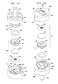
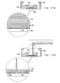
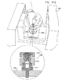
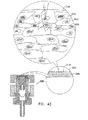
ここで、本発明の好ましい実施例に従って構成され、作動する、分解されたSEM互換性サンプル容器の、各々反対側に向いた簡略的な分解図である、図1A乃至図5Bを参照する。図1A及び図1Bに示されるように、SEM互換性サンプル容器は、閉鎖の容易さ及び速さを向上させるため配列された、参照番号100及び102により指し示された、第1及び第2の互いにねじ込まれるエンクロージャ要素を備えている。エンクロージャ要素100及び102は、第1のエンクロージャ要素100に形成された突出部104を、第2のエンクロージャ要素102に形成されたバヨネット式ソケット106に接続することにより閉鎖の容易さ及び速度を向上するように構成されている。
Reference is now made to FIGS. 1A-5B, which are simplified exploded views, each directed to the opposite side, of an exploded SEM compatible sample container constructed and operative in accordance with a preferred embodiment of the present invention. As shown in FIGS. 1A and 1B, SEM-compatible sample containers are first and second indicated by
突出部104は、好ましくは、第1の突出部108と、第2の突出部110とを備え、これらの突出部は、バヨネット式ソケット106に形成された第1の凹部112と第2の凹部114とに連通する。突出部108の凹部112との初期における係合は、例えば、移動や取り扱いの間のSEM互換性サンプル容器の不意の損傷を防止するように、エンクロージャ要素100及び102の緩い係合を提供する。突出部108の凹部114との引き続く係合は、エンクロージャ要素100及び102のきっちりとした係合を提供する。エンクロージャ要素100及び102は、プラスチックで鋳造され、導電金属コーティングで被覆されるのが好ましい。
The
第1のエンクロージャ要素100は、好ましくは、液体サンプルエンクロージャを形成し、略中央アパーチャ106を持つベース表面104を有する。図2A及び図2Bに詳細に示される、電子ビーム透過性で流体不透過性の膜サブアッセンブリ128は、図3A、3B及び図5A、5Bに示されるように、アパーチャ106に対向してこれを覆って、エンクロージャ要素100の内部に着座している。エンクロージャ要素100内に適切に配置されたサブアッセンブリ108を備えるサンプル皿部は、図3A乃至図5Bに示されるように、参照番号129により指し示されている。
The
更に図2A及び図2Bを参照すると、電子ビーム透過性で流体不透過性の膜130が、接着剤により、その中心で機械式支持格子134を形成する格子支持要素132に接着される。該膜130は、アメリカ合衆国、UT、オレムのモックステック社から市販されている、カタログ番号LWN00033等のポリイミド膜を含むのが好ましい。格子134は、図面で縮尺通りには示されておらず、ユーザーがSEM互換性サンプル容器に対してサンプル領域の位置を同定することを援助するように基準配位インジケータ機能を提供するため非対称列のアパーチャを形成するように形成されるのが好ましく、イスラエル、キブツマーガンマイケルのスロン社から市販されているステンレススチルシートの好ましくは、化学エッチングにより形成されるのが好ましい。接着剤は、アメリカ合衆国、CT06790の51グリーンウッドロードのダイアミックス社から市販されている、カタログ番号1193MVLVであるのが好ましい。
Still referring to FIGS. 2A and 2B, an electron beam transmissive and fluid
液体サンプルエンクロージャ形成リング136は、好ましくは、例えばアメリカ合衆国、CT06790の51グリーンウッドロードのダイアミックス社から市販されている、カタログ番号1193MVLV等の接着により、電子ビーム透過性流体不透過性の膜130に接着されるのが好ましい。リング136は、スペイン、バルセロナ市のイルペンから市販されている、例えばカタログ番号692106001000等のPMMA(ポリメチルメタクリレート)から形成されるのが好ましく、約20マイクロリットルの体積で約2mmの高さを備えた液体サンプルエンクロージャを画定するのが好ましい。好ましくは、リング136は、傾斜壁を有する液体サンプルエンクロージャ138を画定するように構成され、第1のエンクロージャ要素100においてリング136を着実に着座させるように、第1のエンクロージャ要素100の突出部144に形成された凹部142と係合するように作用する周囲リム140がその外側表面上に形成されている。
The liquid sample
代替例として、膜130は、ポリアミド、ポリアミド−イミド、ポリエチレン、ポリピロール、「パーロディオン」、「コロディオン」、「カプトン」、「フォームバー」、「ビニレック」、「バットバー」、「ピオロフォルム」、「パリレーネ」、二酸化シリコン、一酸化シリコン、又は、カーボン、或いは、前掲したものの任意の組み合わせ、又は、他の任意の適切な材料から形成されてもよい。
As an alternative, the
図1A、1B、5A及び5Bに示されるように、Oリング146は、リング136と、第2のエンクロージャ要素102の内部表面150との間に配置されているのが好ましい。Oリング146は、エンクロージャ要素100及び102が緊密な係合であるとき、要素100及び102のねじ込み係合が密封係合であるべき必要性を無くすように作用する。
As shown in FIGS. 1A, 1B, 5A and 5B, the O-
第2のエンクロージャ要素102には、走査型電子顕微鏡の標本ステージの適切な凹部(図示せず)に着座するように配列された、略中央スタブ122が形成されるのが好ましい。図1A乃至図10に示される容器は、従来の走査型電子顕微鏡の従来のスタブ用凹部に適合するサイズで働き、それが何であれ、変形する必要はないことが、本発明の特別な特徴である。スタブの様々な形態及びサイズを、様々な走査型電子顕微鏡に適合するように提供することができることが認められよう。
The
エンクロージャ要素100及び102は、容器を、適切な多重容器ホルダー内に容易に着座させることを可能にし、更にユーザーがエンクロージャ要素100及び102をねじ込み開閉することを援助するため、径方向に延在する夫々の位置決め保持突起部154及び156が設けられるのが好ましい。好ましくは、各々のエンクロージャ要素100及び102上の突起部154及び156の相対的な方位角方向の配置は、図4A及び図4Bに示されるように、これら突起部間の相対的な方位角方向の整列が、要素間のねじ込み閉鎖の所望の度合いを指し示すようになっているのが好ましい。
本発明の別の実施例では、サンプル皿部がエンクロージャ100及び102を備えていてもよいことが認められよう。
ここで、図1A乃至図5BのSEM互換性サンプル容器の作動態様を作動の3段階で各々示した3つの断面図である、図6A、6B及び6Cを参照する。図6Aは、エンクロージャ要素100及び102を閉鎖する前の図1Bに示される配位で配列されている、液体サンプル160を蓄えた図1A乃至図5Bの容器を示している。なお、液体サンプルは、表面張力に起因して、液体サンプルエンクロージャ116からは流れ出ない。電子ビーム透過性で流体不透過性の膜110が、図6Aにおいて、略平坦であるように示されている。
It will be appreciated that in other embodiments of the invention, the sample pan may include
Reference is now made to FIGS. 6A, 6B, and 6C, which are three cross-sectional views illustrating the operational aspects of the SEM compatible sample container of FIGS. FIG. 6A shows the container of FIGS. 1A-5B with a
図6Bは、周囲からの液体サンプルエンクロージャ138の密封を生成するエンクロージャ要素100及び102の間の完全な係合に続く中間状態にある、図6Aの容器を示している。電子ビーム透過性で流体不透過性の膜130が、この態様におけるその密封の結果生じた液体サンプルエンクロージャ138の圧力形成に起因して、外方にしなっていることが見て取れる。支持格子134は、略平坦であるように示されている。
FIG. 6B shows the container of FIG. 6A in an intermediate state following full engagement between
図6Cは、典型的には、10−2〜10−6ミリバールの真空でSEMの脱ガス環境に配置されたときの図6Bの容器を示している。この環境では、電子ビーム透過性で流体不透過性の膜130と支持格子134とが、図6Bの周囲環境に配置されたときよりも、より大きい度合いで外方にしなっていることが見て取れる。更には、電子ビーム透過性で流体不透過性の膜130は、図6Bの周囲環境で生じたものよりも大きい度合いで格子134の隙間を通って隙間内に入り込もうとしていることが理解できる。
FIG. 6C shows the container of FIG. 6B when placed in a SEM degassing environment with a vacuum of typically 10 −2 to 10 −6 mbar. In this environment, it can be seen that the electron beam transmissive and fluid
ここで、図1A乃至図6CのSEM互換性サンプル容器を使用した、細胞成長、液体除去、液体追加、密封及びSEMへの挿入の各状態の簡略断面図である、図7A、7B、7C、7D及び7Eを参照する。典型的な細胞培養状況を示す、図7Aを参照すると、サブアッセンブリ128を内部に配置させたエンクロージャ要素100は、図1Aに示された配置態様にあり、液体媒体164内の細胞162は液体サンプルエンクロージャ138内に配置され、これらの細胞162が、電子ビーム透過性で流体不透過性の膜130に接触して横たわっている。
Here, FIGS. 7A, 7B, 7C are simplified cross-sectional views of cell growth, liquid removal, liquid addition, sealing, and insertion into the SEM using the SEM compatible sample containers of FIGS. 1A-6C. See 7D and 7E. Referring to FIG. 7A, which illustrates a typical cell culture situation, the
図7Bは、典型的には吸引によって液体サンプルエンクロージャ138から液体を除去した状態を示し、図7Cは、液体サンプルエンクロージャ138に液体を追加した状態を示している。液体の除去及び追加を多数回に亘って液体サンプルエンクロージャ138内のサンプルに関して実行してもよい。好ましくは、液体除去及び追加のため用いられる装置は、電子ビーム透過性で流体不透過性の膜130の意図しない破裂を防止するように、設計され、備え付けられるのがよい。
FIG. 7B shows a state where liquid is removed from the
図7Dは、図7Cに示される細胞162を液体媒体164内に含む容器の閉鎖状態を示している。図7Eは、SEM168のステージ166上に挿入される閉鎖容器を図1Bの配位で示している。容器の配位が図7Eに示されたものとは反対であるSEMが存在することが認められよう。
FIG. 7D shows the closed state of the container containing the
図7A乃至図7Dは、液体サンプルエンクロージャ138に関する液体の追加又は除去に拘わらず、サンプルを含む液体の少なくとも一部分が電子ビーム透過性で流体不透過性の膜130と接触したままとなる状況を例示している。この状況は、電子ビーム透過性で流体不透過性の膜130に、サンプルの一部が吸収され、そうでなければ、接着される状況を含んでいてもよい。サンプルを含む液体の例は、細胞、培養菌、血液、バクテリア及び無細胞材料を含んでいてもよい。
FIGS. 7A-7D illustrate a situation where at least a portion of the liquid containing the sample remains in contact with the electron beam transmissive and fluid
図1A乃至図6CのSEM互換性サンプル容器を使用した、電子ビーム透過性で流体不透過性の膜130と接触したサンプル含有液体、密封及びSEMへの挿入の各状態の簡略断面図である、図8A、8B及び8Cを参照する。図8A乃至図8Cは、サンプルを含む液体170の少なくとも一部分が電子ビーム透過性で流体不透過性の膜130と接触しているが、それに接着されていない状況を例示している。サンプルを含む液体の例には、例えば、ミルク、化粧用クリーム、ペイント、インク、及び、液体形態の薬剤等、様々な乳濁液及び懸濁液がある。図8A乃至図8Bで、サブアッセンブリ128を内部に配置させたエンクロージャ要素10は、図1Aに示される配位にあることが見て取れよう。
FIG. 7 is a simplified cross-sectional view of a sample-containing liquid in contact with an electron beam permeable fluid
図8Bは、サンプル170を含む容器の閉鎖状態を示している。図8Cは、SEM168のステージ166上に挿入された、図1Bの配位にある、閉鎖容器を示している。容器の配位が図8Cに示されたものとは反対であるSEMが存在することが認められよう。
FIG. 8B shows the closed state of the container containing the
ここで、図1A乃至図6CのSEM互換性サンプル容器を使用した、サンプルのSEM検査の簡略図及び断面図である、図9を参照する。図9に示されるように、参照番号171により指し示された容器は、SEMにより発生された電子ビーム172が電子ビーム透過性で流体不透過性の膜130を通過し、容器171内のサンプル174を含む液体に照射されように、SEM168のステージ166上に配置されている。サンプル174からの後方散乱電子は、電子ビーム透過性で流体不透過性の膜130を通過し、SEM168の一部を形成する検出器176により検出される。例えば2次電子検出器178等の1つ以上の追加の検出器を設けてもよい。電子ビーム励起に起因してサンプル174により放射されるX線放射を検出するためのX線検出器(図示せず)を設けてもよい。電子ビーム励起に起因してサンプル174により放射される放射を検出するためのカソドルミネセント検出器(図示せず)を設けてもよい。
Reference is now made to FIG. 9, which is a simplified and cross-sectional view of SEM inspection of a sample using the SEM compatible sample container of FIGS. 1A-6C. As shown in FIG. 9, the container designated by
ここで、本発明の好ましい実施例に係る容器171内のサンプル174との電子ビーム相互作用の詳細を概略的に示す図10を追加的に参照する。なお、本発明は、図10に示されるように、それらの平均的な原子番号により互いから区別される特徴群の高いコントラストの画像形成を可能にしている。図10では、比較的高い平均原子番号を有する、細胞核180は、周囲の核質182よりも電子をより大きく後方散乱させることが示されている。
Reference is now additionally made to FIG. 10, which schematically shows details of electron beam interaction with a
なお、本発明の好ましい実施例によれば、約2ミクロンまでの深さのサンプル内部の画像形成は、図10に示されるように、50KeVより低いエネルギーレベルを有する電子に対して達成可能であり、電子ビーム透過性で流体不透過性の膜130より下方に位置する細胞核180が画像形成される。
It should be noted that according to a preferred embodiment of the present invention, imaging within a sample up to about 2 microns deep can be achieved for electrons having an energy level lower than 50 KeV, as shown in FIG. The cell nuclei 180 located below the electron beam permeable and fluid
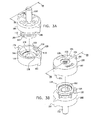
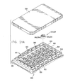
ここで、本発明の別の好ましい実施例に従って構成され、作動する、分解された走査型電子顕微鏡(SEM)の互換性サンプル容器の、各々反対側に向いた簡略的な分解図である、図11A乃至図15Bを参照する。図11A及び図11Bに示されるように、SEM互換性サンプル容器は、第2のエンクロージャ要素202に形成されたバヨネット式ソケット206に第1のエンクロージャ要素200に形成された突出部204を接続することにより、閉鎖の容易さ及び速さを向上させるように配列された、参照番号200及び202により指し示された、第1及び第2の相互に係合されるエンクロージャ要素を備えている。
Here, a simplified exploded view, each directed to the opposite side, of a disassembled scanning electron microscope (SEM) compatible sample container constructed and operative in accordance with another preferred embodiment of the present invention, FIG. Refer to FIGS. 11A to 15B. As shown in FIGS. 11A and 11B, the SEM compatible sample container connects the
突出部204は、好ましくは、第1の突出部208と、第2の突出部210とを備え、これらの突出部は、バヨネット式ソケット206に形成された第1の凹部212と第2の凹部214とに連通する。突出部208の凹部212との初期における係合は、例えば、移動や取り扱いの間のSEM互換性サンプル容器の不意の損傷を防止するように、エンクロージャ要素200及び202の緩い係合を提供する。突出部208の凹部214との引き続く係合は、エンクロージャ要素200及び202のきっちりとした係合を提供する。エンクロージャ要素200及び202は、プラスチックで鋳造され、導電金属コーティングで被覆されるのが好ましい。
The
第1のエンクロージャ要素200は、好ましくは、液体サンプルエンクロージャを形成し、略中央アパーチャ226を持つベース表面224を有する。図12A及び図12Bに詳細に示される、電子ビーム透過性で流体不透過性の膜サブアッセンブリ228は、図13A、13B及び図15A、15Bに示されるように、アパーチャ226に対向してこれを覆って、エンクロージャ要素200の内部に着座している。エンクロージャ要素200内に適切に配置されたサブアッセンブリ228を備えるサンプル皿部は、図13A乃至図15Bに示されるように、参照番号229により指し示されている。
The
更に図12A及び図12Bを参照すると、電子ビーム透過性で流体不透過性の膜230が、接着剤により、機械式支持格子232に接着される。該膜230は、アメリカ合衆国、UT、オレムのモックステック社から市販されている、カタログ番号LWN00033等のポリイミド膜を含むのが好ましい。該支持格子232は、その中心で機械式支持格子234を形成する。格子234は、図面で縮尺通りには示されておらず、ユーザーがSME互換性サンプル容器に対するサンプル領域の位置を同定することを援助するように基準配位同定機能を提供するべく非対称列のアパーチャを形成して構成されるのが好ましく、更には、イスラエル、キブッツ・マーガン・マイケルのスロン社から市販されているステンレススチルシートの光化学的エッチングにより形成されるのが好ましい。
Still referring to FIGS. 12A and 12B, an electron beam permeable, fluid
液体サンプルエンクロージャ形成リング236は、好ましくは、アメリカ合衆国、CT06790、トリングトン、51グリーンウッドロード、ダイアミックス社から市販されている、カタログ番号1193MVLV等の接着剤により、電子ビーム透過性で流体不透過性の膜240に接着される。リング236は、スペイン、バルセロナ市のイルペンから市販されている、例えばカタログ番号692106001000等のPMMA(ポリメチルメタクリレート)から形成されるのが好ましく、約20マイクロリットルの体積で約2mmの高さを備えた液体サンプルエンクロージャを画定するのが好ましい。好ましくは、リング236は、傾斜壁を有する液体サンプルエンクロージャ238を画定するように構成される。更に、リング246は、その外側表面に、第1のエンクロージャ要素200にリング236を確実に着座させるように第1のエンクロージャ要素200の突出部241に形成された凹部240と係合するように作用する周囲リム239が形成されるのが好ましい。
The liquid sample
図11A、11B、15A及び15Bに示されるように、ダイヤフラム242は、リング236と、第2のエンクロージャ要素202の内側表面244との間に配置されるのが好ましい。好ましくは、ダイヤフラム242は、Oリング部246から一体成形され、該Oリング部246には、伸張可能シート部248が密封されている。ダイヤフラム242は、約50のショア硬度を有するシリコンゴムから成形されるのが好ましく、シート部248は、0.2〜0.3mmの厚さを有するのが好ましい。ダイヤフラム242は、エンクロージャ要素200及び202が、緊密な係合にあるとき、要素200及び202の係合が密封係合であるべき必要性を無くすように、並びに、その動的圧力及び静的圧力のリリーフを提供するように作動する。
As shown in FIGS. 11A, 11B, 15A and 15B, the
第2のエンクロージャ要素202には、走査型電子顕微鏡の標本ステージの適切な凹部(図示せず)に着座するように配列された、貫通ボア253を有する略中央スタブ252が形成されるのが好ましい。ボア253は、ダイヤフラム242の一方の側と(SEM)互換性サンプル容器が配置されている環境との間に流体連通チャンネルを形成することにより、ダイヤフラム242が圧力リリーフを提供することを可能にする。図11A乃至図20に示される容器は、従来の走査型電子顕微鏡の従来のスタブ用凹部に適合するサイズで働き、それが何であれ、変形する必要はないことが、本発明の特別な特徴である。スタブの様々な形態及びサイズを、様々な走査型電子顕微鏡に適合するように提供することができることが認められよう。
The
エンクロージャ要素200及び202は、容器を、適切な多重容器ホルダー内に容易に着座させることを可能にし、更にユーザーがエンクロージャ要素200及び202を開閉することを援助するため、径方向に延在する夫々の位置決め保持突起部254及び256が設けられるのが好ましい。好ましくは、各々のエンクロージャ要素200及び202上の突起部254及び256の相対的な方位角方向の配置は、図14A及び図14Bに示されるように、これら突起部間の相対的な方位角方向の整列が、要素間の緊密な係合を指し示すようになっているのが好ましい。
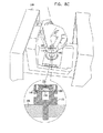
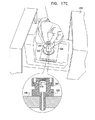
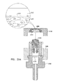
ここで、図11A乃至図15BのSEM互換性サンプル容器の作動態様を作動の3段階で各々示した3つの断面図である、図16A、16B及び16Cを参照する。図16Aは、エンクロージャ要素200及び202を閉鎖する前に、図11Bに示された配位で配列されている、液体サンプル260を蓄えた図11A乃至図15Bの容器を示している。なお、液体サンプルは、表面張力に起因して、液体サンプルエンクロージャ238からは流れ出ない。電子ビーム透過性で流体不透過性の膜230が、図16Aにおいて、略平坦であるように示されている。
Reference is now made to FIGS. 16A, 16B, and 16C, which are three cross-sectional views illustrating the operational aspects of the SEM compatible sample container of FIGS. 11A-15B, respectively, in three stages of operation. FIG. 16A shows the container of FIGS. 11A-15B storing
図16Bは、周囲からの液体サンプルエンクロージャ238の密封を生成するエンクロージャ要素200及び202の間の完全な係合に続く中間状態にある、図16Aの容器を示している。ダイヤフラム242が、この態様におけるその密封の結果生じた液体サンプルエンクロージャ238の圧力形成に起因して、外方にしなっていることが見て取れる。本実施例では、電子ビーム透過性で流体不透過性の膜230及びその支持格子212も、この態様におけるその密封の結果生じた液体サンプルエンクロージャ238内の圧力形成に起因して、外方にしなっているが、ダイヤフラム242の作用に起因して、かなりより小さい程度にしか、しなっていない。これは、図16Bと図6Bとを比較することにより、理解することができる。支持格子234は、略平坦であるように示されている。
FIG. 16B shows the container of FIG. 16A in an intermediate state following full engagement between
図16Cは、典型的には、10−2〜10−6ミリバールの真空でSEMの脱ガス環境に配置されたときの図16Bの容器を示している。この環境では、ダイヤフラム242が、図16Bの周囲環境のときよりもより大きい度合いで外方にしなり、電子ビーム透過性で流体不透過性の膜230と支持格子234とが、図16Bの周囲環境に配置されたときよりも、より大きい度合いで外方にしなっているが、ダイヤフラム242の作用に起因して、図6Cの実施例のときよりも、かなり小さい度合いでしかしなっていないことが見て取れる。これは、図16Cと図6Cとを比較することにより、理解することができる。
FIG. 16C shows the container of FIG. 16B when placed in a SEM degassing environment with a vacuum of typically 10 −2 to 10 −6 mbar. In this environment, the
なお、電子ビーム透過性で流体不透過性の膜230は、図16Bの周囲環境で生じたものよりも大きい度合いで格子234の隙間を通って隙間内に入り込もうとしているが、ダイヤフラム242の作用に起因して、図6Cの実施例のときよりもかなり小さい度合いでしかしなっていないことが理解できる。これは、図16Cと図6Cとを比較することにより、理解することができる。
It should be noted that the electron beam permeable and fluid
ここで、図11A乃至図16CのSEM互換性サンプル容器を使用した、細胞成長、液体除去、液体追加、密封及びSEMへの挿入の各状態の簡略断面図である、図17A、17B、17C、17D及び17Eを参照する。図7Aと同一で、典型的な細胞の培養状況を示す、図17Aを参照すると、サブアッセンブリ228を内部に配置させたエンクロージャ要素200が、図11Aに示される配位にあり、液体媒体264中の細胞262が、液体サンプルエンクロージャ238内に配置され、細胞262が、電子ビーム透過性で流体不透過性の膜230に接触して横たわっていることが示されている。
Here, FIGS. 17A, 17B, and 17C are simplified cross-sectional views of cell growth, liquid removal, liquid addition, sealing, and insertion into the SEM using the SEM compatible sample containers of FIGS. Reference is made to 17D and 17E. Referring to FIG. 17A, which is identical to FIG. 7A and shows a typical cell culture situation,
図7Bと同一の図17Bは、典型的には吸引により、液体サンプルエンクロージャ238からの液体の除去を示し、図7Cと同一の図17Cは、液体サンプルエンクロージャ238への液体の追加を示している。多数回に亘る液体の除去及び追加は液体サンプルエンクロージャ238内のサンプルに関して生じ得ることが理解されよい。好ましくは、液体除去及び追加のため用いられる装置は、電子ビーム透過性で流体不透過性の膜230の意図しない破裂を防止するように、設計され、備え付けられるのがよい。
FIG. 17B, identical to FIG. 7B, shows the removal of liquid from the
図17Dは、図17Cに示される細胞262を液体媒体264内に含む容器の閉鎖状態を示している。図17Eは、SEM268のステージ266上に挿入される閉鎖容器を図11Bの配位で示している。容器の配位が図17Eに示されたものとは反対であるSEMが存在することが認められよう。
FIG. 17D shows the closed state of the container containing the
図17A乃至図17Dは、液体サンプルエンクロージャ238に関する液体の追加又は除去に拘わらず、サンプルを含む液体の少なくとも一部分が電子ビーム透過性で流体不透過性の膜230と接触したままとなる状況を例示している。この状況は、電子ビーム透過性で流体不透過性の膜230に、サンプルの一部が吸収され、そうでなければ、接着される状況を含んでいてもよい。サンプルを含む液体の例は、細胞、培養菌、血液、バクテリア及び無細胞材料を含んでいてもよい。
17A-17D illustrate a situation in which at least a portion of the liquid containing the sample remains in contact with the electron beam transmissive and fluid
図11A乃至図16CのSEM互換性サンプル容器を使用した、電子ビーム透過性で流体不透過性の膜230と接触したサンプル含有液体、密封及びSEMへの挿入の各状態の簡略断面図である、図18A、18B及び18Cを参照する。図18A乃至図18Cは、サンプルを含む液体270の少なくとも一部分が電子ビーム透過性で流体不透過性の膜230と接触しているが、それに接着されていない状況を例示している。サンプルを含む液体の例には、例えば、ミルク、化粧用クリーム、ペイント、インク、及び、液体形態の薬剤等、様々な乳濁液及び懸濁液がある。図18A乃至図18Bで、サブアッセンブリ208を内部に配置させた、エンクロージャ要素200は、図11Aに示される配位にあることが見て取れよう。図18Aは図8Aと同一である。
FIG. 17 is a simplified cross-sectional view of sample-containing liquid in contact with an electron beam permeable fluid
図18Bは、サンプル270を含む容器の閉鎖状態を示している。図18Cは、SEM268のステージ266上に挿入された、図11Bの配位にある、閉鎖容器を示している。容器の配位が図18Cに示されたものとは反対であるSEMが存在することが認められよう。
FIG. 18B shows the closed state of the container containing the
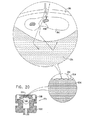
ここで、図11A乃至図16CのSEM互換性サンプル容器を使用した、サンプルのSEM検査の簡略図及び断面図である、図19を参照する。図19に示されるように、参照番号271により指し示された容器は、SEMにより発生された電子ビーム272が電子ビーム透過性で流体不透過性の膜230を通過し、容器271内のサンプル274を含む液体に照射されように、SEM268のステージ266上に配置されている。サンプル274からの後方散乱電子は、電子ビーム透過性で流体不透過性の膜230を通過し、SEM268の一部を形成する検出器276により検出される。例えば2次電子検出器等の1つ以上の追加の検出器を設けてもよい。電子ビーム励起に起因してサンプル274により放射されるX線放射を検出するためのX線検出器(図示せず)を設けてもよい。また、電子ビーム励起に起因してサンプル274により放射される放射を検出するためのカソドルミネセント検出器(図示せず)を設けてもよい。
Reference is now made to FIG. 19, which is a simplified and cross-sectional view of a sample SEM inspection using the SEM compatible sample container of FIGS. 11A-16C. As shown in FIG. 19, the container designated by
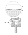
ここで、本発明の好ましい実施例に係る容器270内のサンプル274との電子ビーム相互作用の詳細を概略的に示す図20を追加的に参照する。なお、本発明は、図20に示されるように、それらの平均的な原子番号により互いから区別される特徴群の高いコントラストの画像形成を可能にしている。図20では、比較的高い平均原子番号を有する、細胞核280が、周囲の核質282よりも電子をより大きく後方散乱させることが示されている。
Reference is now additionally made to FIG. 20, which schematically shows details of electron beam interaction with a
なお、本発明の好ましい実施例によれば、約2ミクロンまでの深さのサンプル内部の画像形成は、図20に示されるように、50KeVより低いエネルギーレベルを有する電子に対して達成可能であり、電子ビーム透過性で流体不透過性の膜230より下方に位置する細胞核280が画像形成される。
Note that, according to a preferred embodiment of the present invention, imaging inside samples up to about 2 microns deep can be achieved for electrons having energy levels below 50 KeV, as shown in FIG. The cell nuclei 280 located below the
ここで、図1A乃至図20に示された型式のSEM互換性サンプル容器で使用する顕微鏡検査前の多重サンプルホルダーの簡略的な分解図である、図21A及び図21Bを参照する。更に、顕微鏡検査前の多重サンプルホルダーを、覆われていない状態、及び、覆われて組み立てられた状態で各々示した、簡略図である、図21A及び図21Bを参照する。図21A及び図21Bに示されるように、顕微鏡検査前の多重サンプルホルダーは、ベース部300と、頂部要素302と、カバー304と、を備えるのが好ましい。好ましくは、カバー304が顕微鏡検査前の多重サンプルホルダーの内部に無菌状態を維持するため設けられる。
Reference is now made to FIGS. 21A and 21B, which are simplified exploded views of a multiple sample holder prior to microscopy for use with an SEM compatible sample container of the type shown in FIGS. 1A-20. Reference is further made to FIGS. 21A and 21B, which are simplified diagrams showing the multiple sample holders before microscopy, in an uncovered state and in a covered and assembled state, respectively. As shown in FIGS. 21A and 21B, the multiple sample holder before microscopic examination preferably includes a
ベース部300は、好ましくは、プラスチック材料から射出成形され、容器支持収容部306の列を形成する。各々の容器支持収容部306は、光透明底部壁を有する凹部308により形成されるのが好ましい。該光透明底部壁を通して光学顕微鏡の検査を実行することができる。図1A乃至図8Cで参照番号100により指し示され、図11A乃至図15Bで200により指し示されたエンクロージャ要素で、各凹部308に隣接して、図1A乃至図5Bで参照番号154により指し示された突起部を収容するように配置された、一対の互いに整列した対の直立相互間隔突起部310が形成され、これにより方位角方向の整列を固定するのが好ましい。
ベース部300は、顕微鏡検査前の多重サンプルホルダーの内部で所望レベルの湿度を維持するため使用される液体を保持するようになった、複数の液体リザーバー312を形成するのが好ましい。ベース部300は、床部320が形成されるのが好ましい。
The base 300 preferably forms a plurality of
カバー304が、顕微鏡検査前の多重サンプルホルダーの内部の無菌状態を維持するため提供される。カバー304は、光に対して透明であるのが好ましい。図21A乃至図22Bの顕微鏡検査前の多重サンプルホルダーは、光学顕微鏡、遠心分離機及び自動位置決め装置等の従来の細胞生物学的設備と互換性があるように寸法が定められるのが好ましい。好ましい寸法は、85mm×127mmである。
A
ここで、吸引装置及びピペットを伴った、図21A乃至図22Bの顕微鏡検査前の多重サンプルホルダーの簡略図である、図22A、22B及び22Cを参照する。図22Aを参照すると、参照番号350により指し示された吸引装置が吸引源に導管354を介して連結されたマニホルド352を備えることが示されている。マニホルド352は、均一に間隔を隔てられたニードル356の直線状列と連通するのが好ましい。マニホルド352は、個々のニードル356の向上した吸引作用及び独立した吸引作用を提供するため、その一方の端部でオリフィス357が形成されている。
Reference is now made to FIGS. 22A, 22B and 22C, which are simplified illustrations of the multiple sample holder of FIGS. 21A-22B prior to microscopic examination, with a suction device and pipette. Referring to FIG. 22A, it is shown that the suction device indicated by
一対のスペーサー358が、マニホルド352に取り付けられるか、又は、マニホルドと一体成形されている。スペーサー358は、ニードル356の直線状列と一列に並んで配置される。これらのスペーサー358は、ニードル356が、図1A乃至図10では参照番号130、図11A乃至図20では参照番号230によって指し示された電子ビーム透過性で流体不透過性の膜と係合しないことを確実にする。スペーサー358は、ニードル356がサンプル皿部内のサンプルを追い出すことを防止するように、図3A乃至図5Bでは参照番号129、図13A乃至図15Bでは参照番号229によって指し示されたサンプル皿部の側部に沿って整列されるように凹部359と係合する。
A pair of
図22Aに示されるように、容器支持位置306は、顕微鏡検査前の多重サンプルホルダー上で直線状列に配列されている。かくして、図22Bに示されるように、列毎に、ニードル356のうち4つがサンプル皿部と係合する。
As shown in FIG. 22A, the container support positions 306 are arranged in a linear row on the multiple sample holder before microscopy. Thus, as shown in FIG. 22B, for each row, four of the
図22Cは、従来のピペット360を用いて個々のサンプル皿部に液体を追加した状態を示している。図1A乃至図10では参照番号130、図11A乃至図20では230で指し示された電子ビーム透過性で流体不透過性の膜とピペットとの意図しない係合を防止するため、カラー要素362が、ピペット360と連係して使用するため設けられてもよい。
FIG. 22C shows a state in which liquid is added to each sample pan using a
ここで、本発明の好ましい実施例に従って構成され、作動するSEMベースのサンプル検査システムの簡略図である、図23を参照する。図23に示されるように、複数の顕微鏡検査前の多重サンプルホルダー600は、各々が図1A乃至図20に示された型式の多数のSEM互換性サンプル容器602を含み、細菌培養器604内に配置された状態で示されている。好ましくは、関心のあるサンプルを同定するため、参照番号606で示されるように、容器602がホルダー600内に取り付けられた状態で、容器602内のサンプルの光学顕微鏡検査が実行される。好ましくは、倒立光学顕微鏡608がこの目的のため用いられる。
Reference is now made to FIG. 23, which is a simplified illustration of an SEM-based sample inspection system constructed and operative in accordance with a preferred embodiment of the present invention. As shown in FIG. 23, a plurality of pre-microscopic
好ましくは、図示のような例えばロボットアーム等の自動位置決めシステムが、システムを通して、顕微鏡検査前多重サンプルホルダー600及び容器602を搬送するため使用される。1つ以上のステージで手動介入操作が適宜用いられてもよいことが認められよう。
Preferably, an automatic positioning system, such as a robot arm as shown, is used to transport the pre-microscopic
その後、個々の容器602は、ホルダー600から取り外され、取り外し可能な電子顕微鏡標本ステージ610に配置され、次に、走査型電子顕微鏡612内に導入される。その結果得られた画像は、オペレータにより視覚的に検査され、及び/又は、典型的にはコンピュータ614で具現化される従来の画像分析機能により分析される。
Thereafter, the
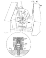
本発明の別の好ましい実施例に従って構成され、作動する、分解された走査型電子顕微鏡(SEM)互換性サンプル容器の、各々反対側に向いた簡略的な分解図である、図24A乃至図28Bを参照する。図24A及び図24Bに示されるように、SEM互換性サンプル容器は、参照番号1100及び1102により各々指し示された第1及び第2のエンクロージャ要素と、閉鎖の容易さ及び速さを向上させるため配列された接続要素1103と、を備えている。エンクロージャ要素1100及び1102と、接続要素1103とは、好ましくは、プラスチックから成形され、導電性金属コーティングで被覆される。
FIGS. 24A-28B are simplified exploded views, each directed to the opposite side, of an exploded scanning electron microscope (SEM) compatible sample container constructed and operative in accordance with another preferred embodiment of the present invention. Refer to As shown in FIGS. 24A and 24B, the SEM-compatible sample container is provided with first and second enclosure elements indicated by
第1のエンクロージャ要素1100は、好ましくは、サンプルエンクロージャを形成し、略中央アパーチャ1106を持つベース表面1104を有する。図25A及び図25Bに詳細に示される、電子ビーム透過性で流体不透過性の膜サブアッセンブリ1108は、図26A、26B及び図28A、28Bに示されるように、アパーチャ1106に対向してこれを覆って、エンクロージャ要素1100の内部に着座している。エンクロージャ要素1100内に適切に配置されたサブアッセンブリ1108を備えるサンプル皿部は、図26A乃至図28Bに示されるように、参照番号1109により指し示されている。
The
更に図25A及び図25Bを参照すると、電子ビーム透過性で流体不透過性の膜1110が、接着剤により、格子支持要素1111に接着される。該膜1110は、アメリカ合衆国、UT、オレムのモックステック社から市販されている、カタログ番号LWN00033等のポリイミド膜を含むのが好ましい。格子支持要素1110は、その中央部で機械支持格子1112を形成する。格子1112は、図面で縮尺通りには示されておらず、SEM互換性サンプル容器に対するサンプル領域の位置をユーザーが同定することを援助するように基準配位インジケータ機能を提供するため非対称的なアパーチャ列を形成するように構成されるのが好ましく、イスラエル、キブツマーガンマイケルのシュロン社から市販されているステンレススチルシートの光化学エッチングにより形成されるのが好ましい。
Still referring to FIGS. 25A and 25B, an electron beam transmissive and fluid
サンプルエンクロージャ形成リング1114は、好ましくは、接着剤により、電子ビーム透過性で流体不透過性の膜1110に接着されている。該接着剤は、例えばアメリカ合衆国、CT06790、トリングトン、51グリーンウッズロードのダイアミックス社から市販されている、例えば、カタログ番号1193MVLV等が挙げられる。リング1114は、スペイン、バルセロナ市のイルペンから市販されている、例えばカタログ番号692106001000等のPMMA(ポリメチルメタクリレート)から形成されるのが好ましく、約20マイクロリットルの体積で約2mmの高さを備えた液体サンプルエンクロージャを画定するのが好ましい。好ましくは、リング1114は、第1のエンクロージャ要素1100内にリング1114を確実に着座させるように第1のエンクロージャ要素1100の突出部1120内に形成された凹部1119と係合するように作動する周囲リム1118がその外側表面上に形成されている。
The sample
図24A、24B、28A及び28Bに示されるように、第1のOリング1121は、第2のエンクロージャ要素1102の内側表面1122と、接続要素1103との間に配置されるのが好ましい。第2のOリング1126は、接続要素1103と、サブアッセンブリ1108のリング1114との間に配置されるのが好ましい。エンクロージャ要素1100及び1102並びに接続要素1103を密封係合する必要性を無くすため、エンクロージャ要素1100及び1102並びに接続要素1103が、きっちりとした係合状態にあるとき、Oリング1121及び1126が作用する。
As shown in FIGS. 24A, 24B, 28A, and 28B, the first O-
接続要素1103は、凹部1128を有するのが好ましい。接続要素1103には、図28A及び図28Bに示される、突起部1130が形成され、該突起部は凹部1128内に突出している。
The connecting
ポジショナー1132は、2つの直立した可撓性突起部1134から構成されるのが好ましく、各々は、突起部1134の端部1138に形成されたリッジ1136を備える。ポジショナー1132は、プラスチックから成形されるのが好ましい。図28A及び28Bに示されるように、突起部1134は、接続要素1103の凹部1128内に挿入されたとき互いに押圧し、一旦、リッジ1136が接続要素1103の突起部1130に着座されたならば、直立位置へとスナップ式に戻る。
The
ポジショナー1132は、リム1142から延在する、夫々の径方向に延在する位置決め保持突起部1140が設けられているのが好ましい。位置決め保持突起部1140は、リング1114内でのポジショナー1132の回転を防止するためリング1114の溝1117内に着座されている。
The
コイルスプリング1144は、リム1142と、突起部1134のリッジ1136との間にポジショナー1132に配置されている。スプリング1144は、硬化ステンレス鋼から形成されるのが好ましい。
The
ポジショナー1132及びスプリング1144は、エンクロージャ要素1100及び1102と接続要素1103とが密接に係合した状態にあるとき、電子ビーム透過性で流体不透過性の膜1110に接触して非液体サンプルを上方に移動させるように作用する。
The
第1のエンクロージャ要素1100は、接続要素1103に形成されたバヨネット式ソケット1156に、第1のエンクロージャ要素1100に形成された突出部1154を接続することによって接続要素1103と係合する。
The
突出部1154は、第1の突出部1158と、第2の突出部1160とを備え、これらの突出部は、バヨネット式ソケット115内に形成された、第1の凹部1162と、第2の凹部1164と、に連通する。突出部1158の凹部1162への初期における係合は、例えば、移動や取り扱いの間のSEM互換性サンプル容器の不意の損傷を防止するように、第1のエンクロージャ要素1100と接続要素1103との緩い係合を提供する。突出部1158の凹部1164との引き続く係合は、エンクロージャ要素1100と接続要素1103とのきっちりとした係合を提供する。
The projecting
第2のエンクロージャ要素1102は、第2のエンクロージャ要素1102に形成されたバヨネット式ソケット1176に、接続要素1103に形成された突出部1154を接続することによって接続要素1103と係合する。
The
突出部1174は、第1の突出部1178と、第2の突出部1180とを備え、これらの突出部は、バヨネット式ソケット1176内に形成された、第1の凹部1182と、第2の凹部1184と、に連通する。突出部1178の凹部1182への初期における係合は、例えば、移動や取り扱いの間のSEM互換性サンプル容器の不意の損傷を防止するように、第2のエンクロージャ要素1102と接続要素1103との緩い係合を提供する。突出部1178の凹部1184との引き続く係合は、エンクロージャ要素1102と接続要素1103とのきっちりとした係合を提供する。
The projecting
第2のエンクロージャ要素1102は、走査型電子顕微鏡の標本ステージの適切な凹部(図示せず)に着座するように配列された、略中央スタブ1190が形成されるのが好ましい。図24A乃至図33に示される容器は、従来の走査型電子顕微鏡の従来のスタブ用凹部に適合するサイズで働き、それが何であれ、変形する必要はないことが、本発明の特別な特徴である。スタブの様々な形態及びサイズを、様々な走査型電子顕微鏡に適合するように提供することができることが認められよう。
The
エンクロージャ要素1100及び1102と、接続要素1103とは、容器を、適切な多重容器ホルダー内に容易に着座させることを可能にし、更にユーザーがエンクロージャ要素1100及び1102と接続要素1103とを開閉することを援助するため、径方向に延在する夫々の位置決め保持突起部1194、1196及び1198が設けられるのが好ましい。好ましくは、各々のエンクロージャ要素1100及び1102と接続要素1103上の夫々の突起部1194、1196及び1198の相対的な方位角方向の配置は、図27A及び図27Bに示されるように、これら突起部間の相対的な方位角方向の整列が、要素間のきっちりとした係合を指し示すようになっているのが好ましい。
ここで、図24A乃至図28BのSEM互換性サンプル容器の作動態様を作動の3段階で各々示した3つの断面図である、図29A、29B及び29Cを参照する。図29Aは、エンクロージャ要素1100及び1102と接続要素1103を閉鎖する前の図24Bに示される配位で配列されている、組織サンプル1260を蓄えた図24A乃至図28Bの容器を示している。電子ビーム透過性で流体不透過性の膜1110が、図19Aにおいて、略平坦であるように示されている。
Reference is now made to FIGS. 29A, 29B, and 29C, which are three cross-sectional views illustrating the operational aspects of the SEM compatible sample container of FIGS. 24A-28B, respectively, in three stages of operation. FIG. 29A shows the container of FIGS. 24A-28B
図29Bは、周囲からの組織サンプルエンクロージャ1116の密封を生成するエンクロージャ要素1100及び1102と接続要素1103との間の完全な係合に続く中間状態にある、図29Aの容器を示している。なお、組織サンプル1260はポジショナー1132により発揮された力に起因して、電子ビーム透過性で流体不透過性の膜1110と緊密に接触している。電子ビーム透過性で流体不透過性の膜1110が、この態様におけるその密封の結果生じた組織サンプルエンクロージャ1116の圧力形成に起因して、外方にしなっていることが見て取れる。支持格子1112は、略平坦であるように示されている。
FIG. 29B shows the container of FIG. 29A in an intermediate state following full engagement between
図29Cは、典型的には、10−2〜10−6ミリバールの真空でSEMの脱ガス環境に配置されたときの図29Bの容器を示している。この環境では、電子ビーム透過性で流体不透過性の膜1110と支持格子1112とが、図29Bの周囲環境に配置されたときよりも、より大きい度合いで外方にしなっていることが見て取れる。更には、電子ビーム透過性で流体不透過性の膜1110は、図36Bの周囲環境で生じたものよりも大きい度合いで格子1112の隙間を通って隙間内に入り込もうとしていることが理解できる。
FIG. 29C shows the container of FIG. 29B when placed in a SEM degassing environment with a vacuum of typically 10 −2 to 10 −6 mbar. In this environment, it can be seen that the electron beam permeable and fluid
ここで、図24A乃至図29CのSEM互換性サンプル容器を使用した、サンプルを含む組織とSEMへの挿入とを示す、簡略図及び断面図である、図30を参照する。図30は、SEM1266のステージ1264に挿入される、図24Bの配位にある閉鎖容器を示している。容器の配位が図30に示されたものとは反対であるSEMが存在することが認められよう。
Reference is now made to FIG. 30, which is a simplified and cross-sectional view showing the tissue containing the sample and insertion into the SEM using the SEM compatible sample container of FIGS. 24A-29C. FIG. 30 shows the closed container in the configuration of FIG. 24B inserted into the
ここで、図24A乃至図29BのSEM互換性サンプル容器の様々な作動配位を、SEM互換性サンプル容器を使用したSEM内への作動及び挿入の様々な段階で示した、図31A、31B、31C、31D及び31Eを参照する。 Here, various operational configurations of the SEM compatible sample containers of FIGS. 24A-29B are shown in various stages of operation and insertion into the SEM using the SEM compatible sample containers, FIGS. 31A, 31B, Reference is made to 31C, 31D and 31E.
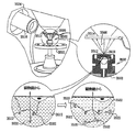
図31Aは、典型的には培養器1270内に配置された、細胞支持要素、細胞成長要素、流体フィルター要素、及び、細胞ステージ1268等、粒子又は細胞を支持するように作動する複数の可撓性支持要素を示している。細胞ステージ1268は、該ステージ上で細胞の成長を可能にするか、又は、その代わりに、該ステージ上の成長細胞の密着を可能にするように働く。各々の細胞ステージ1268は、リング1274により取り囲まれた多孔性膜1272により形成されるのが好ましく、細胞1278を含むサンプル1276を支持する。多孔性膜1272は、アメリカ合衆国、MA、アクトンのコーニングから市販されている、カタログ番号3470、タウンズウェルプレート等、ポリエステルから形成されるのが好ましい。細胞1278は、液体媒体中で細胞1278の基底側上で多孔性膜1272により支持されるのが好ましい。多孔性膜1272は、図31Aに示されるように、培養器1270内の培養の間等、作動の段階の間に、サンプル内の所望レベルの湿度を維持するように働く。
FIG. 31A illustrates a plurality of flexibility operating to support particles or cells, such as a cell support element, cell growth element, fluid filter element, and
細胞1278又は粒子は、細胞又は粒子を含む流体を多孔性膜1272を通して吸着又はフィルター処理することにより、可撓性支持要素上に沈着させることができることが認められよう。
It will be appreciated that the
図31Aに示されるように、細胞1278の分子又は外部から追加した分子等の分子1279は、細胞1278の頂上側部に提供されるのが好ましい。好ましくは、分子1279は、電子顕微鏡で視覚化することができる例えば金コロイド等の電子密度の高い構造に連結される。
As shown in FIG. 31A, a
図31Bは、以下で特定されるように、細胞1278を支持し、好ましくは非剛性材料から形成されたプラットフォーム1282上に取り付けられた細胞ステージ1268を含んでいる以外では、図24A乃至図28Bの容器と同一であるSEM互換性サンプル容器1280を示している。容器1280は、エンクロージャ要素1100及び1102と接続要素1103との閉鎖前に、図24Bに示された配位に配列されている。細胞成長プラットフォーム1282は、図24A乃至図30の実施例のポジショナー1132に対応する、適切に構成されたポジショナー1284上に取り付けられている。典型的には、細胞1278は、細胞ステージ1268がプラットフォーム1282上に取り付けられていない間にも、培養器1270内の細胞ステージ1268上で成長する。細胞ステージ1268のプラットフォーム1282上の取り付け、並びに、細胞ステージ1268を備えたプロットフォーム1282のポジショナー1284上への取り付けは、典型的には、SEM検査が行われる直前に行われる。
FIG. 31B supports
図31Cは、周囲からの、参照番号1286により指し示された細胞サンプルエンクロージャの密封を生成するエンクロージャ要素1100及び1102と接続要素1103との間の完全な係合に直ぐに続く、図31Bの容器1280を示している。なお、細胞1278を含むサンプルはポジショナー1284により発揮された力に起因して、電子ビーム透過性で流体不透過性の膜1110と緊密に接触している。電子ビーム透過性で流体不透過性の膜1110が、この態様におけるその密封の結果生じた組織サンプルエンクロージャ1286の圧力形成に起因して、外方にしなっていることが見て取れる。支持格子1112は、略平坦であるように示されている。
FIG. 31C shows
図31Dは、典型的には、10−2〜10−6ミリバールの真空でSEMの脱ガス環境に配置されたときの図31Cの容器を示している。この環境では、電子ビーム透過性で流体不透過性の膜1110と細胞ステージ1268とが、図31Cの周囲環境に配置されたときよりも、より大きい度合いで外方にしなっていることが見て取れる。更には、電子ビーム透過性で流体不透過性の膜1110は、図31Cの周囲環境で生じたものよりも大きい度合いで格子1112の隙間を通って隙間内に入り込もうとしていることが理解できる。この環境では格子1112も外方に僅かにしなっていることが理解できる。
FIG. 31D shows the container of FIG. 31C when placed in a SEM degassing environment with a vacuum of typically 10 −2 to 10 −6 mbar. In this environment, it can be seen that the electron beam permeable and fluid
図31Eは、SEM1266のステージ1264に挿入される、図24Bの配位にある閉鎖容器1280を示している。容器の配位が図31Eに示されたものとは反対であるSEMが存在することが認められよう。
FIG. 31E shows the
ここで、図24A乃至図30のSEM互換性サンプル容器を使用した、サンプルのSEM検査の簡略図及び断面図である、図32を参照する。図32に示されるように、参照番号1290により指し示された容器は、SEMにより発生された電子ビーム1292が電子ビーム透過性で流体不透過性の膜1110(図24A乃至図31D)を通過し、容器1290内のサンプル1294を含む組織に照射されように、SEM1266のステージ1264上に配置されている。サンプル1294からの後方散乱電子は、電子ビーム透過性で流体不透過性の膜1110を通過し、SEMの一部を形成する検出器1296により検出される。例えば2次電子検出器1298等の1つ以上の追加の検出器を設けてもよい。電子ビーム励起に起因してサンプル1294により放射されるX線放射を検出するためのX線検出器(図示せず)を設けてもよい。電子ビーム励起に起因してサンプル1294により放射される放射を検出するためのカソドルミネセント検出器(図示せず)を設けてもよい。
Reference is now made to FIG. 32 which is a simplified and cross-sectional view of a sample SEM inspection using the SEM compatible sample container of FIGS. 24A-30. As shown in FIG. 32, the container designated by reference numeral 1290 passes through a membrane 1110 (FIGS. 24A-31D) in which an
ここで、本発明の好ましい実施例に係る容器1290内のサンプル1294との電子ビーム相互作用の詳細を概略的に示す図33を追加的に参照する。なお、本発明は、図33に示されるように、それらの平均的な原子番号により互いから区別される特徴群の高いコントラストの画像形成を可能にしている。図33では、比較的高い平均原子番号を有する、細胞核1300は、周囲の核質1302よりも電子をより大きく後方散乱させることが示されている。
Reference is now additionally made to FIG. 33, which schematically shows details of electron beam interaction with a
なお、本発明の好ましい実施例によれば、約2ミクロンまでの深さのサンプル内部の画像形成は、図33に示されるように、50KeVより低いエネルギーレベルを有する電子に対して達成可能であり、電子ビーム透過性で流体不透過性の膜1110より下方に位置する細胞核1300が画像形成される。
It should be noted that according to a preferred embodiment of the present invention, imaging inside samples up to about 2 microns deep can be achieved for electrons having energy levels below 50 KeV, as shown in FIG. The
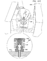
ここで、本発明の別の好ましい実施例に従って構成され、作動する、分解された走査型電子顕微鏡(SEM)の互換性サンプル容器の、各々反対側に向いた簡略的な分解図である、図34A乃至図38Bを参照する。図34A及び図34Bに示されるように、SEM互換性サンプル容器は、参照番号2100及び2102により各々指し示された、第1及び第2のエンクロージャ要素と、閉鎖の容易さ及び速さを向上させるように配列された、接続要素2103と、を備えている。エンクロージャ要素2100及び2102と、接続要素2103とは、プラスチックから成形され、導電性金属コーティングで被覆されるのが好ましい。
Here, a simplified exploded view, each directed to the opposite side, of a disassembled scanning electron microscope (SEM) compatible sample container constructed and operative in accordance with another preferred embodiment of the present invention, FIG. Reference is made to FIGS. 34A to 38B. As shown in FIGS. 34A and 34B, the SEM compatible sample container improves the ease and speed of closure with the first and second enclosure elements indicated by
第1のエンクロージャ要素2100は、好ましくは、サンプルエンクロージャを形成し、略中央アパーチャ2106を持つベース表面2104を有する。図35A及び図35Bに詳細に示される、電子ビーム透過性で流体不透過性の膜サブアッセンブリ2108は、図36A、36B及び図38A、38Bに示されるように、アパーチャ2106に対向してこれを覆って、エンクロージャ要素2100の内部に着座している。エンクロージャ要素2100内に適切に配置されたサブアッセンブリ2108を備えるサンプル皿部は、図36A乃至図38Bに示されるように、参照番号2109により指し示されている。
The
更に図35A及び図35Bを参照すると、電子ビーム透過性で流体不透過性の膜2110が、接着剤により、格子支持要素2111に接着される。該膜2110は、アメリカ合衆国、UT、オレムのモックステック社から市販されている、カタログ番号LWN00033等のポリイミド膜であるのが好ましい。格子支持要素2111は、その中央部で機械式支持格子2112を形成する。格子2112は、図面で縮尺通りには示されておらず、ユーザーがSEM互換性サンプル容器に対してサンプル領域の位置を同定することを援助するように基準配位インジケータ機能を提供するため非対称列のアパーチャを形成するように形成されるのが好ましく、イスラエル、キブツマーガンマイケルのスロン社から市販されているステンレススチルシートの好ましくは、化学エッチングにより形成されるのが好ましい。サンプルエンクロージャ形成リング2113は、好ましくは、例えばアメリカ合衆国、CT06790の51グリーンウッドロードのダイアミックス社から市販されている、カタログ番号1193MVLV等の接着剤により、電子ビーム透過性流体不透過性の膜2110に接着されるのが好ましい。リング2113は、スペイン、バルセロナ市のイルペンから市販されている、例えばカタログ番号692106001000等のPMMA(ポリメチルメタクリレート)から形成されるのが好ましく、約20マイクロリットルの体積で約2mmの高さを備えたサンプルエンクロージャを画定するのが好ましい。好ましくは、リング2113は、複数の径方向に分布した溝2115を形成するように構成された傾斜壁を有するサンプルエンクロージャ2114を画定するように構成される。リング21143は、第1のエンクロージャ要素2100においてリング2113を着実に着座させるように、第1のエンクロージャ要素2100の突出部2118に形成された凹部2117と係合するように作用する周囲リム2116がその外側表面上に形成されているのが好ましい。
Still referring to FIGS. 35A and 35B, an electron beam transmissive and fluid
図34A、34B、38A及び38Bに示されるように、ダイヤフラム2119が、Oリング部2120から一体成形され、該Oリング部2120には、伸張可能シート部2121が密封されているのがよい。ダイヤフラム2119は、第2のエンクロージャ要素2102の内側表面2126と、接続要素2103との間に配置されるのが好ましい。Oリング2126は、接続要素2103と、サブアッセンブリ2108のリング2113との間に配置されるのが好ましい。ダイヤフラム2119とOリング2126とは、エンクロージャ要素2100及び2102と接続要素2103とが緊密な係合にあるとき、要素2100及び2102と接続要素2103との係合が密封係合であるべき必要性を無くすように、並びに、その動的圧力及び静的圧力リリーフを提供するように作動する。
As shown in FIGS. 34A, 34B, 38A, and 38B, a
接続要素2103は、凹部2128を有するのが好ましい。接続要素2103には、凹部2128内に突出する、図38A及び38Bに示される周囲突起部2130が形成されている。
The connecting
ポジショナー2132が、2つの直立した可撓性突起部2134から構成されるのが好ましく、各々は、突起部2134の端部2138に形成されたリッジ2136を備える。ポジショナー2132は、プラスチックから成形されるのが好ましい。図38A及び38Bに示されるように、突起部2134は、接続要素2103の凹部2128内に挿入されたとき互いに押圧し、一旦、リッジ2136が接続要素2103の突起部2130に着座されたならば、直立位置へとスナップ式に戻る。
The
ポジショナー2132は、周囲リム2142から延在する、夫々の径方向に延在する位置決め保持突起部2140が設けられているのが好ましい。位置決め保持突起部2140は、リング2113内でのポジショナー2132の回転を防止するためリング2113の溝2115内に着座されている。
The
コイルスプリング2144は、リム2142と、突起部2134のリッジ2136との間でポジショナー2132上に配置されている。スプリング2144は、硬化ステンレス鋼から形成されるのが好ましい。
The
ポジショナー2132及びスプリング2144は、エンクロージャ要素2100及び2102と、接続要素2103とが緊密に係合した状態にあるとき、電子ビーム透過性で流体不透過性の膜2110に接触して非液体サンプルを上方に移動させるように作用する。
The
第1のエンクロージャ要素2100は、接続要素2103に形成されたバヨネット式ソケット2156に、第1のエンクロージャ要素2100に形成された突出部2154を接続することによって接続要素2103と係合する。
The
突出部2154は、第1の突出部2158と、第2の突出部2160とを備え、これらの突出部は、バヨネット式ソケット2156内に形成された、第1の凹部2162と、第2の凹部2164と、に連通する。突出部2158の凹部2162への初期における係合は、例えば、移動や取り扱いの間のSEM互換性サンプル容器の不意の損傷を防止するように、第1のエンクロージャ要素2100と接続要素2103との緩い係合を提供する。突出部2158の凹部2164との引き続く係合は、エンクロージャ要素2100と接続要素2103とのきっちりとした係合を提供する。
The projecting
第2のエンクロージャ要素2102は、第2のエンクロージャ要素2102に形成されたバヨネット式ソケット2176に、接続要素2103に形成された突出部2174を接続することによって接続要素2103と係合する。
The
突出部2174は、第1の突出部2178と、第2の突出部2180とを備え、これらの突出部は、バヨネット式ソケット2176内に形成された、第1の凹部2182と、第2の凹部2184と、に連通する。突出部2178の凹部2182への初期における係合は、例えば、移動や取り扱いの間のSEM互換性サンプル容器の不意の損傷を防止するように、第2のエンクロージャ要素2102と接続要素2103との緩い係合を提供する。突出部2178の凹部2184との引き続く係合は、エンクロージャ要素2102と接続要素2103とのきっちりとした係合を提供する。
The projecting
第2のエンクロージャ要素2102は、走査型電子顕微鏡の標本ステージの適切な凹部(図示せず)に着座するように配列された、貫通ボア2191を有する略中央スタブ2190が形成されるのが好ましい。図34A乃至図43に示される容器は、従来の走査型電子顕微鏡の従来のスタブ用凹部に適合するサイズで働き、それが何であれ、変形する必要はないことが、本発明の特別な特徴である。スタブの様々な形態及びサイズを、様々な走査型電子顕微鏡に適合するように提供することができることが認められよう。
The
エンクロージャ要素2100及び2102と、接続要素2103とは、容器を、適切な多重容器ホルダー内に容易に着座させることを可能にし、更にユーザーがエンクロージャ要素2100及び2102と接続要素2103とを開閉することを援助するため、径方向に延在する夫々の位置決め保持突起部2194、2196及び2198が設けられるのが好ましい。好ましくは、各々のエンクロージャ要素2100及び2102と接続要素2103上の夫々の突起部2194、2196及び2198の相対的な方位角方向の配置は、図37A及び図37Bに示されるように、これら突起部間の相対的な方位角方向の整列が、要素間のきっちりとした係合を指し示すようになっているのが好ましい。
ここで、図34A乃至図38BのSEM互換性サンプル容器の作動態様を作動の3段階で各々示した3つの断面図である、図39A、39B及び39Cを参照する。図39Aは、エンクロージャ要素2100及び2102と接続要素2103を閉鎖する前の図34Bに示される配位で配列されている、組織サンプル2260を蓄えた図34A乃至図38Bの容器を示している。電子ビーム透過性で流体不透過性の膜2110が、図39Aにおいて、略平坦であるように示されている。
Reference is now made to FIGS. 39A, 39B, and 39C, which are three cross-sectional views illustrating the operational aspects of the SEM compatible sample container of FIGS. 34A-38B, respectively, in three stages of operation. FIG. 39A shows the container of FIGS. 34A-38B
図39Bは、周囲からの組織サンプルエンクロージャ2114の密封を生成する、エンクロージャ要素2100及び2102と接続要素2103との間の完全な係合に続く、図39Aの容器を示している。なお、組織サンプル2260はポジショナー2132により発揮された力に起因して、電子ビーム透過性で流体不透過性の膜2110と緊密に接触している。ダイヤフラム2119が、この態様におけるその密封の結果として液体サンプルエンクロージャ2114内の圧力形成に起因して外方にしなっていることが見て取れる。電子ビーム透過性で流体不透過性の膜2110が、この態様におけるその密封の結果生じた組織サンプルエンクロージャ2114の圧力形成に起因して、外方にしなっているが、ダイヤフラム2119の作用に起因して、かなりより小さい程度にしか、しなっていないことが見て取れる。これは、図39Bを図29Bに比較することによって理解することができる。支持格子2112は、略平坦であるように示されている。
FIG. 39B shows the container of FIG. 39A following full engagement between
図39Cは、典型的には、10−2〜10−6ミリバールの真空でSEMの脱ガス環境に配置されたときの図39Bの容器を示している。この環境では、ダイヤフラム2119が、図39Bの周囲環境のときよりもより大きい度合いで外方にしなり、電子ビーム透過性で流体不透過性の膜2110と支持格子2112とが、図39Bの周囲環境に配置されたときよりも、より大きい度合いで外方にしなっているが、ダイヤフラム2119の作用に起因して、図29Cの実施例のときよりも、かなり小さい度合いでしかしなっていないことが見て取れる。これは、図39Cと図29Cとを比較することにより、理解することができる。
FIG. 39C shows the container of FIG. 39B when placed in a SEM degassing environment with a vacuum of typically 10 −2 to 10 −6 mbar. In this environment, the
なお、電子ビーム透過性で流体不透過性の膜2110は、図39Bの周囲環境で生じたものよりも大きい度合いで格子2112の隙間を通って隙間内に入り込もうとしているが、ダイヤフラム2119の作用に起因して、図39Cの実施例のときよりもかなり小さい度合いでしかしなっていないことが理解できる。これは、図39Cと図29Cとを比較することにより、理解することができる。
Note that the electron beam transmissive and fluid
ここで、図34A乃至図39CのSEM互換性サンプル容器を使用した、サンプルを含む組織とSEMへの挿入とを示す、簡略図及び断面図である、図40を参照する。図40は、SEM2266のステージ2264に挿入される、図34Bの配位にある閉鎖容器を示している。容器の配位が図40に示されたものとは反対であるSEMが存在することが認められよう。
Reference is now made to FIG. 40, which is a simplified and cross-sectional view showing the tissue containing the sample and insertion into the SEM using the SEM compatible sample container of FIGS. 34A-39C. 40 shows the closed container in the configuration of FIG. 34B inserted into the
ここで、図34A乃至図39BのSEM互換性サンプル容器の様々な作動配位を、様々な作動段階並びにSEM互換性サンプル容器を使用してSEM内に挿入した状態で示した断面図である、図41A、41B、41C、41D及び41Eを参照する。 FIG. 40 is a cross-sectional view showing various operating configurations of the SEM compatible sample container of FIGS. 34A-39B inserted into the SEM using various operating stages and SEM compatible sample containers, Reference is made to FIGS. 41A, 41B, 41C, 41D and 41E.
図41Aは、典型的には培養器2270内に配置された、細胞ステージ1268等、粒子又は細胞を支持するように作動する複数の可撓性支持要素を示している。細胞ステージ2268は、該ステージ上で細胞の成長を可能にするか、又は、その代わりに、該ステージ上の成長細胞の密着を可能にするように働く。各々の細胞ステージ2268は、リング2274により取り囲まれた多孔性膜2272により形成されるのが好ましく、細胞2278を含むサンプル2276を支持する。多孔性膜2272は、アメリカ合衆国、MA、アクトンのコーニングから市販されている、カタログ番号3470、タウンズウェルプレート等、ポリエステルから形成されるのが好ましい。細胞2278は、液体媒体中で細胞2278の基底側上で多孔性膜2272により支持されるのが好ましい。多孔性膜2272は、図41Aに示されるように、培養器2270内の培養の間等、作動の段階の間に、サンプル内の所望レベルの湿度を維持するように働く。
FIG. 41A shows a plurality of flexible support elements operating to support particles or cells, such as
細胞2278又は粒子は、細胞又は粒子を含む流体を多孔性膜2272を通して吸着又はフィルター処理することにより、可撓性支持要素上に沈着させることができることが認められよう。
It will be appreciated that
図41Aに示されるように、細胞2278の分子又は外部から追加した分子等の分子2279は、細胞2278の頂上側部に提供されるのが好ましい。好ましくは、分子2279は、電子顕微鏡で視覚化することができる例えば金コロイド等の電子密度の高い構造に連結される。
As shown in FIG. 41A, a
図41Bは、以下で特定されるように、細胞2276を支持し、好ましくは非剛性材料から形成されたプラットフォーム2282上に取り付けられた細胞ステージ2268を含んでいる以外では、図34A乃至図38Bの容器と同一であるSEM互換性サンプル容器2280を示している。容器2280は、エンクロージャ要素2100及び2102と接続要素2103との閉鎖前に、図34Bに示された配位に配列されている。細胞成長プラットフォーム2282は、図34A乃至図40の実施例のポジショナー2132に対応する、適切に構成されたポジショナー2284上に取り付けられている。典型的には、細胞2278は、細胞ステージ2268がプラットフォーム2282上に取り付けられていない間にも、培養器2270内の細胞ステージ2268上で成長する。細胞ステージ2268のプラットフォーム2282上の取り付け、並びに、細胞ステージ2268を備えたプロットフォーム2282のポジショナー2284上への取り付けは、典型的には、SEM検査が行われる直前に行われる。
FIG. 41B supports the
図41Cは、周囲からの、参照番号2286により指し示された細胞サンプルエンクロージャの密封を生成するエンクロージャ要素2100及び2102と接続要素2103との間の完全な係合に直ぐに続く、図41Bの容器2280を示している。なお、細胞2278を含むサンプルはポジショナー2284により発揮された力に起因して、電子ビーム透過性で流体不透過性の膜2110と緊密に接触している。電子ビーム透過性で流体不透過性の膜1110が、この態様におけるその密封の結果生じた組織サンプルエンクロージャ2286の圧力形成に起因して、外方にしなっていることが見て取れるが、ダイヤフラム2119の作用に起因して、図31Cの実施例のときよりもかなり小さい度合いでしかしなっていないことが見て取れる。これは、図41Cと図31Cとを比較することにより、理解することができる。支持格子2112は、略平坦であるように示されている。
FIG. 41C shows
図41Dは、典型的には、10−2〜10−6ミリバールの真空でSEMの脱ガス環境に配置されたときの図41Cの容器を示している。この環境では、電子ビーム透過性で流体不透過性の膜2110と細胞ステージ2268とが、図41Cの周囲環境に配置されたときよりも、より大きい度合いで外方にしなっていることが見て取れる。更には、電子ビーム透過性で流体不透過性の膜2110は、図41Cの周囲環境で生じたものよりも大きい度合いで格子2119の隙間を通って隙間内に入り込もうとしているが、ダイヤフラム2119の作用に起因して、図31Dの実施例のときよりもかなり小さい度合いでしかしなっていないことが見て取れる。これは、図41Dと図31Dとを比較することにより、理解することができる。この環境では格子2112も外方に僅かにしなっていることが理解できる。
FIG. 41D shows the container of FIG. 41C when placed in a SEM degassing environment with a vacuum of typically 10 −2 to 10 −6 mbar. In this environment, it can be seen that the electron beam permeable and fluid
図41Eは、SEM2266のステージ2264に挿入される、図34Bの配位にある閉鎖容器2280を示している。容器の配位が図41Eに示されたものとは反対であるSEMが存在することが認められよう。
FIG. 41E shows the
ここで、図34A乃至図40のSEM互換性サンプル容器を使用した、サンプルのSEM検査の簡略図及び断面図である、図42を参照する。図42に示されるように、参照番号2290により指し示された容器は、SEMにより発生された電子ビーム2292が電子ビーム透過性で流体不透過性の膜2110(図34A乃至図41E)を通過し、容器2290内のサンプル2294を含む組織に照射されように、SEM2266のステージ2264上に配置されている状態で示されている。サンプル2294からの後方散乱電子は、電子ビーム透過性で流体不透過性の膜2110を通過し、SEMの一部を形成する検出器2296により検出される。例えば2次電子検出器2298等の1つ以上の追加の検出器を設けてもよい。電子ビーム励起に起因してサンプル2294により放射されるX線放射を検出するためのX線検出器(図示せず)を設けてもよい。電子ビーム励起に起因してサンプル2294により放射される放射を検出するためのカソドルミネセント検出器(図示せず)を設けてもよい。
Reference is now made to FIG. 42, which is a simplified and cross-sectional view of an SEM inspection of a sample using the SEM compatible sample container of FIGS. 34A-40. As shown in FIG. 42, the container designated by reference numeral 2290 passes through the membrane 2110 (FIGS. 34A-41E) in which the
ここで、本発明の好ましい実施例に係る容器2290内のサンプル2294との電子ビーム相互作用の詳細を概略的に示す図43を追加的に参照する。なお、本発明は、図43に示されるように、それらの平均的な原子番号により互いから区別される特徴群の高いコントラストの画像形成を可能にしている。図43では、比較的高い平均原子番号を有する、細胞核2300は、周囲の核質2302よりも電子をより大きく後方散乱させることが示されている。
Reference is now additionally made to FIG. 43, which schematically shows details of electron beam interaction with a
なお、本発明の好ましい実施例によれば、約2ミクロンまでの深さのサンプル内部の画像形成は、図43に示されるように、50KeVより低いエネルギーレベルを有する電子に対して達成可能であり、電子ビーム透過性で流体不透過性の膜2110より下方に位置する細胞核2300が画像形成される。
It should be noted that according to a preferred embodiment of the present invention, imaging inside a sample up to about 2 microns deep can be achieved for electrons having an energy level lower than 50 KeV, as shown in FIG. The
ここで、本発明の好ましい実施例に従って構成され、作動するSEMベースのサンプル検査システムの簡略図である、図44を参照する。図44に示されるように、好ましくは、図示のような例えばロボットアーム等の自動位置決めシステムが、システムを通して、多数のSEM互換性サンプル容器2602を搬送するため使用される。1つ以上のステージで手動介入操作が適宜用いられてもよいことが認められよう。
Reference is now made to FIG. 44, which is a simplified illustration of an SEM-based sample inspection system constructed and operative in accordance with a preferred embodiment of the present invention. As shown in FIG. 44, preferably an automatic positioning system such as a robotic arm as shown is used to transport a number of SEM
その後、個々の容器2602は、電子顕微鏡標本ステージ2610に配置され、次に、走査型電子顕微鏡2612内に導入される。その結果得られた画像は、オペレータにより視覚的に検査され、及び/又は、典型的にはコンピュータ2614で具現化される従来の画像分析機能により分析される。
Thereafter, the
ここで、サンプルホルダー3000を使用した倒立光学顕微鏡内でのサンプルの検査の簡単な断面図である、図45を参照する。サンプルホルダー3000は、好ましくは、光透過膜3002により画定され、液体媒体中でサンプル3004を支持する。膜3002は、光がそこを貫通してサンプル3004に当たることを可能にするように作用する。サンプルは、流体、又は、例えば細胞3006等の微粒子構成要素を含んでいてもよいことが認められよう。
Reference is now made to FIG. 45, which is a simple cross-sectional view of sample inspection within an inverted optical microscope using the
図45に示されるように、サンプルホルダー3000は、倒立光学顕微鏡3012の標本ステージ3011内に配置された、支持リング3010により支持された状態で示されている。倒立光学顕微鏡3012の対物レンズ3016の屈折率に類似した屈折率を有する、例えばオイル又はゲル等の浸漬流体3014は、最適な光学特性を提供するため膜3002と対物レンズ3016との間に配置することができる。
As shown in FIG. 45, the
好ましくは10ミクロン厚より小さい、膜3002を備えたサンプルホルダー3000は、従来のガラススライドと比較したとき、レンズからサンプルへの距離の短さ、並びに、膜3002のより弱い光学活性の故に、明視野、暗視野、共焦顕微鏡、及び、全反射照明蛍光顕微鏡を始めとした様々な方法によって、改善された画像形成を提供することができることが認められよう。
The
ここで、電子ビームの照射に起因したサンプル又はサンプル容器への損傷を減少又は防止する、電子顕微鏡のための方法論を図示する図46を参照する。サンプル、特に有機分子又は高分子のサンプルは、電子ビーム照射に起因した損傷を被ることが知られている。出願人は、図1A乃至図45を参照して上述された、サンプルホルダーの膜への電子ビーム損傷は、該膜への電子ビーム照射に起因して発生し得ること、及び、その代わりに又は追加的に、膜を攻撃し得る反応種を生成する、サンプル上への電子ビーム照射に起因して発生し得ることを認識した。 Reference is now made to FIG. 46 illustrating a methodology for an electron microscope that reduces or prevents damage to the sample or sample container due to electron beam irradiation. Samples, particularly organic or polymer samples, are known to suffer damage due to electron beam irradiation. Applicants have noted that the electron beam damage to the film of the sample holder described above with reference to FIGS. 1A-45 can occur due to electron beam irradiation on the film and, alternatively, or Additionally, it has been recognized that this can occur due to electron beam irradiation on the sample, which generates reactive species that can attack the membrane.
本発明の特別の特徴は、電子ビーム誘導損傷を防止し又は減少させるための方法論が、電子ビーム照射誘導損傷に敏感である有機材料又は高分子材料のサンプルを提供し、該サンプルに、電子ビーム照射誘導損傷を少なくとも部分的に防止する保護材料を追加し、電子顕微鏡内で該サンプル及び該保護材料に電子ビームを照射する、各工程を備えているということである。 A particular feature of the present invention is that a methodology for preventing or reducing electron beam induced damage provides a sample of organic or polymeric material that is sensitive to electron beam irradiation induced damage, wherein the sample includes an electron beam That is, a protective material that at least partially prevents irradiation-induced damage is added, and each step of irradiating the sample and the protective material with an electron beam in an electron microscope is provided.
また、本発明の特別の特徴は、電子ビーム誘導損傷を防止し又は減少させるための方法論が、サンプルエンクロージャ内にサンプルを配置し、該サンプルエンクロージャは、電子ビーム照射誘導損傷に敏感である電子ビーム透過性で流体不透過性の膜を含み、更に該膜に対して密封され且つ該膜と共に該サンプルエンクロージャを形成する周囲エンクロージャを備えており、該サンプルに、該膜への電子ビーム照射誘導損傷を少なくとも部分的に防止する保護材料を追加し、電子顕微鏡内で該サンプル及び該保護材料に電子ビームを照射する、各工程を備えているということでもある。 Also, a special feature of the present invention is that a methodology for preventing or reducing electron beam induced damage places a sample in a sample enclosure, the sample enclosure being sensitive to electron beam irradiation induced damage. A permeable, fluid impermeable membrane, and further comprising a surrounding enclosure sealed to the membrane and forming the sample enclosure with the membrane, the sample being subjected to electron beam radiation induced damage to the membrane It also means that a step of adding a protective material that at least partially prevents the sample and irradiating the sample and the protective material with an electron beam in an electron microscope is provided.
膜は、該膜への電子ビーム照射又はサンプルへの電子ビーム照射から生じる電子ビーム誘導損傷に敏感であり得ることが認められよう。
ここで、図46を参照すると、図11A乃至図15BのSEM互換性サンプル容器を使用したサンプルのSEM検査の簡単な図及び断面図が示されている。図46を参照して本文中に説明された保護方法論は、SEM顕微鏡に限定されるものではなく、例えば、TEM顕微鏡等の他の種類の電子顕微鏡にも等しく適用可能であることが認められよう。
It will be appreciated that the film may be sensitive to electron beam induced damage resulting from electron beam irradiation of the film or electron beam irradiation of the sample.
Referring now to FIG. 46, there is shown a simple view and cross-sectional view of a sample SEM inspection using the SEM compatible sample container of FIGS. 11A-15B. It will be appreciated that the protection methodology described herein with reference to FIG. 46 is not limited to SEM microscopes and is equally applicable to other types of electron microscopes such as, for example, TEM microscopes. .
図46に示されるように、参照番号3500により指し示された容器は、SEMにより発生された電子ビーム3506が、図1A乃至図44に示される電子ビーム透過性で流体不透過性の膜と同一であり得る電子ビーム透過性で流体不透過性の膜3510を通過し、容器3500内のサンプル3512を含む液体に照射されように、SEM3504のステージ3502上に配置されている状態で示されている。サンプル3512は、典型的には、有機材料又は高分子材料を含んでいる。サンプル3512からの後方散乱電子は、電子ビーム透過性で流体不透過性の膜3510を通過し、SEMの一部を形成する検出器3514により検出される。例えば2次電子検出器3516等の1つ以上の追加の検出器を設けてもよい。電子ビーム励起に起因してサンプル3512により放射されるX線放射を検出するためのX線検出器(図示せず)を設けてもよい。電子ビーム励起に起因してサンプル3512により放射される放射を検出するためのカソドルミネセント検出器(図示せず)を設けてもよい。
As shown in FIG. 46, the container designated by
図46に象徴的に示されるように、電子ビームのサンプル3512及び/又は膜3510上の照射は、例えば、イオン又は遊離基等の反応種を生成し得る。これらの反応種は、サンプル3512及び/又は膜3510に損傷を引き起こし得る。
As symbolically shown in FIG. 46, irradiation of the
本発明の好ましい実施例によれば、サンプル3512及び/又は膜3510への損傷を防止するように反応種を少なくとも部分的に不活性にするため、保護材料がサンプル3512に追加される。適切な保護材料の例には、4−(2−ヒドロキシル)−1−ピペラジンエタンスルホン酸(HEPES−KOH)、(25mM、pH7.5);トリスヒドロキシメチルアミノメタン(Tris−HCl)、10mM、pH7.5;Dグルコース、25mM;D−ソルビトール、25mM;L−アスコルビン酸、50mM;L−カルノシン、50mM;ニコチンアミドアデニンジヌクレオチド(NADH)、25mM;並びに、ウシ胎児血清、10%(v/v)が含まれている。
In accordance with a preferred embodiment of the present invention, protective material is added to
図46に象徴的に示されるように、参照材料3520により指し示された保護材料の分子は、参照番号3522により指し示された反応種と反応しようとし、かくして、それらを不活性にし、サンプル3512及び/又は膜3510への損傷を減少又は防止する。これをしなければ、当該損傷は、サンプル3512又は膜3510への電子ビーム3506の照射の結果として生じるであろう。
As symbolically shown in FIG. 46, the molecules of the protective material indicated by
本発明は、特定に示され、上述されたものに限定されないことは当業者により認められよう。本発明の範囲は、前記した明細書を読むとき当業者に想到され、従来技術には存在しないような、上述された様々な特徴の組み合わせ及びサブコンビネーションの両方、並びに、それらの変形及び変更を網羅している。 It will be appreciated by persons skilled in the art that the present invention is not limited to what has been particularly shown and described hereinabove. The scope of the present invention includes both the various feature combinations and sub-combinations described above, as well as variations and modifications thereof, as would occur to those skilled in the art upon reading the foregoing specification and do not exist in the prior art. It is covered.
Claims (130)
サンプルエンクロージャであって、電子ビーム透過性で流体不透過性の膜と、該膜に密封されて該膜と共に前記サンプルエンクロージャを形成する、周囲エンクロージャと、を備える、前記サンプルエンクロージャと、
前記サンプルエンクロージャとの係合を密封するための迅速接続式アタッチメント機能を有する、サンプルエンクロージャの閉鎖部と、
を備える、SEM互換性サンプル容器。 A SEM compatible sample container,
A sample enclosure comprising: an electron beam permeable fluid impermeable membrane; and a surrounding enclosure sealed to the membrane to form the sample enclosure with the membrane;
A closure of the sample enclosure having a quick connect attachment function for sealing engagement with the sample enclosure;
A SEM compatible sample container.
液体サンプルエンクロージャは、電子ビーム透過性で流体不透過性の膜と、該膜に密封されて該膜と共に前記液体サンプルエンクロージャを形成する、周囲エンクロージャと、を備え、
前記サンプルエンクロージャは、50KeVより小さいエネルギーレベルを有する電子によっては透過可能ではない深さで液体を含むことができる、SEM互換性サンプル容器。 A SEM compatible sample container comprising a liquid sample enclosure,
The liquid sample enclosure comprises an electron beam permeable and fluid impermeable membrane and a surrounding enclosure sealed to the membrane to form the liquid sample enclosure with the membrane;
The SEM compatible sample container, wherein the sample enclosure can contain liquid at a depth that is not permeable by electrons having an energy level of less than 50 KeV.
サンプル皿部であって、電子ビーム透過性で流体不透過性の膜と、該膜に密封されて該膜と共に前記サンプル皿部を形成する、周囲エンクロージャと、を備える、前記サンプル皿部と、
前記サンプル皿部の周りに配列され、該皿部の内部と共に、前記膜を電子が通過するためのアパーチャを形成する、外側エンクロージャと、
を備える、SEM互換性サンプル容器。 A SEM compatible sample container,
A sample pan portion comprising: an electron beam permeable fluid impermeable membrane; and a surrounding enclosure sealed to the membrane to form the sample pan portion with the membrane; and
An outer enclosure arranged around the sample pan and forming an aperture for passing electrons through the membrane with the interior of the pan;
A SEM compatible sample container.
電子が通過するためのアパーチャを形成するエンクロージャと、
前記エンクロージャの内部に配置され、電子ビーム透過性で流体不透過性の膜を備える、サンプル皿部と、
を備え、
前記アパーチャは、前記膜を通して前記エンクロージャの内部と電子を連通させるように前記膜に対して配置されている、SEM互換性サンプル容器。 A SEM compatible sample container,
An enclosure that forms an aperture for electrons to pass through;
A sample pan disposed within the enclosure and comprising an electron beam permeable and fluid impermeable membrane;
With
The SEM-compatible sample container, wherein the aperture is positioned relative to the membrane to communicate electrons with the interior of the enclosure through the membrane.
アパーチャを形成するサンプル皿部アッセンブリであって、該アパーチャは該アパーチャを通して電子を連通させ、前記サンプル皿部アッセンブリは、少なくとも部分的にサンプルエンクロージャを形成する電子ビーム透過性で流体不透過性の膜を備える、前記サンプル皿部アッセンブリと、
サンプルと係合した状態で直線的な非回転運動をし、これにより前記膜に隣接して前記サンプルを位置決めするように構成された、サンプルポジショナーと、
前記エンクロージャとの係合を密封するための迅速接続式アタッチメント機能を有する閉鎖部と、
を備え、
前記アパーチャは、前記サンプルが前記膜に隣接した状態で、該アパーチャを通して電子を連通させるように前記膜に対して配置され、該アパーチャは前記膜を貫通する、SEM互換性サンプル容器。 A SEM compatible sample container,
A sample pan assembly forming an aperture, the aperture communicating electrons through the aperture, wherein the sample pan assembly is an electron beam transmissive and fluid impermeable membrane that at least partially forms a sample enclosure Comprising the sample dish assembly; and
A sample positioner configured to have a linear non-rotating motion in engagement with the sample, thereby positioning the sample adjacent to the membrane;
A closure having a quick connect attachment function for sealing engagement with the enclosure;
With
The aperture is positioned relative to the membrane such that electrons are in communication through the aperture with the sample adjacent to the membrane, the aperture penetrating the membrane, an SEM compatible sample container.
アパーチャを形成するサンプル皿部アッセンブリであって、該アパーチャは該アパーチャを通して電子を連通させ、前記サンプル皿部アッセンブリは、少なくとも部分的にサンプルエンクロージャを形成する電子ビーム透過性で流体不透過性の膜を備える、前記サンプル皿部アッセンブリと、
前記サンプル皿部アッセンブリと連係した圧力リリーフダイヤフラムと、
を備える、SEM互換性サンプル容器。 A SEM compatible sample container,
A sample pan assembly forming an aperture, the aperture communicating electrons through the aperture, wherein the sample pan assembly is an electron beam transmissive and fluid impermeable membrane that at least partially forms a sample enclosure Comprising the sample dish assembly; and
A pressure relief diaphragm associated with the sample pan assembly;
A SEM compatible sample container.
アパーチャを形成するサンプル皿部アッセンブリであって、該アパーチャは該アパーチャを通して電子を連通させ、前記サンプル皿部アッセンブリは、少なくとも部分的にサンプルエンクロージャを形成する電子ビーム透過性で流体不透過性の膜を備える、前記サンプル皿部アッセンブリと、
前記膜に連係された少なくとも1つの基準配位インジケータと、
を備える、SEM互換性サンプル容器。 A SEM compatible sample container,
A sample pan assembly forming an aperture, the aperture communicating electrons through the aperture, wherein the sample pan assembly is an electron beam transmissive and fluid impermeable membrane that at least partially forms a sample enclosure Comprising the sample dish assembly; and
At least one reference coordination indicator associated with the membrane;
A SEM compatible sample container.
請求項1乃至73のいずれか1項に記載の複数のSEM互換性サンプル容器と、
前記複数のSEM互換性サンプル容器を支持するための支持部と、
を備える、多重サンプル容器システム。 A multi-sample container system prior to microscopy with SEM compatibility,
A plurality of SEM compatible sample containers according to any one of claims 1 to 73;
A support for supporting the plurality of SEM compatible sample containers;
A multi-sample container system.
SEMと、
アパーチャを形成するサンプル皿部アッセンブリであって、該アパーチャは該アパーチャを通して電子を連通させ、前記サンプル皿部アッセンブリは、少なくとも部分的にサンプルエンクロージャを形成する電子ビーム透過性で流体不透過性の膜を備える、前記サンプル皿部アッセンブリと、
前記サンプルエンクロージャ内に配置されたサンプル含有液体からSEM検査の間にX線を受け取るように配置されたX線検出器と、
を備える、SEMシステム。 A SEM system,
SEM,
A sample pan assembly forming an aperture, the aperture communicating electrons through the aperture, wherein the sample pan assembly is an electron beam transmissive and fluid impermeable membrane that at least partially forms a sample enclosure Comprising the sample dish assembly; and
An X-ray detector arranged to receive X-rays during a SEM examination from a sample-containing liquid arranged in the sample enclosure;
An SEM system comprising:
SEMと、
サンプルエンクロージャを有するSEM互換性サンプル容器であって、該サンプルエンクロージャは、電子ビーム透過性で流体不透過性の膜と、該膜に密封されて該膜と共に前記液体サンプルエンクロージャを形成する、周囲エンクロージャと、を備える、前記SEM互換性サンプル容器と、
前記サンプルエンクロージャとの係合を密封するための迅速接続式アタッチメント機能を有する、サンプルエンクロージャの閉鎖部と、
を備える、SEMシステム。 A SEM system,
SEM,
A SEM-compatible sample container having a sample enclosure, the sample enclosure comprising an electron beam permeable fluid impermeable membrane and a surrounding enclosure sealed to the membrane to form the liquid sample enclosure with the membrane And the SEM compatible sample container comprising:
A closure of the sample enclosure having a quick connect attachment function for sealing engagement with the sample enclosure;
An SEM system comprising:
サンプルエンクロージャ内にサンプルを配置する工程であって、該サンプルエンクロージャは、電子ビーム透過性で流体不透過性の膜と、該膜に密封されて該膜と共に前記サンプルエンクロージャを形成する、周囲エンクロージャと、前記サンプルエンクロージャとの係合を密封するための迅速接続式アタッチメント機能を有する、サンプルエンクロージャの閉鎖部と、を備える、前記工程と、
前記サンプルエンクロージャを前記サンプルエンクロージャ閉鎖部で密封する工程と、
前記サンプルエンクロージャを電子ビーム内に配置する工程と、
前記電子ビームと前記サンプルとの相互作用の結果を分析する工程と、
を備える、方法。 A method for performing an inspection with a scanning electron microscope,
Placing a sample in a sample enclosure, the sample enclosure comprising an electron beam permeable fluid impermeable membrane and a surrounding enclosure sealed to the membrane to form the sample enclosure with the membrane; A closure of the sample enclosure having a quick connect attachment function for sealing engagement with the sample enclosure; and
Sealing the sample enclosure with the sample enclosure closure;
Placing the sample enclosure in an electron beam;
Analyzing the result of the interaction between the electron beam and the sample;
A method comprising:
X線の検出と、紫外線から赤外線の範囲における光の検出と、
後方散乱電子の検出と、
2次電子の検出と、のうち少なくとも1つにより実施される、請求項100乃至103のいずれか1項に記載の走査型電子顕微鏡による検査を実行するための方法。 Analysis of the result of the interaction between the sample and the electron beam is
X-ray detection and detection of light in the ultraviolet to infrared range;
Detection of backscattered electrons,
104. A method for performing an inspection with a scanning electron microscope according to any one of claims 100 to 103, performed by at least one of detecting secondary electrons.
サンプルエンクロージャ内にサンプルを配置する工程であって、該サンプルエンクロージャは、電子ビーム透過性で流体不透過性の膜と、該膜に密封されて該膜と共に前記サンプルエンクロージャを形成する、周囲エンクロージャと、前記サンプルエンクロージャとの係合を密封するための迅速接続式アタッチメント機能を有する、サンプルエンクロージャの閉鎖部と、を備える、前記工程と、
前記サンプルを前記膜に隣接して位置決めするように配列されたサンプルポジショナーを配置し、
前記サンプルエンクロージャの閉鎖部を用いて前記サンプルエンクロージャを密封し、
前記サンプルエンクロージャを電子ビーム内に配置し、
前記電子ビームと前記サンプルとの相互作用の結果を分析する、各工程を備える、方法。 A method for performing an inspection with a scanning electron microscope,
Placing a sample in a sample enclosure, the sample enclosure comprising an electron beam permeable fluid impermeable membrane and a surrounding enclosure sealed to the membrane to form the sample enclosure with the membrane; A closure of the sample enclosure having a quick connect attachment function for sealing engagement with the sample enclosure; and
Placing a sample positioner arranged to position the sample adjacent to the membrane;
Sealing the sample enclosure with a closure of the sample enclosure;
Placing the sample enclosure in an electron beam;
A method comprising the steps of analyzing the results of the interaction between the electron beam and the sample.
X線の検出と、紫外線から赤外線の範囲における光の検出と、
後方散乱電子の検出と、
2次電子の検出と、のうち少なくとも1つにより実施される、請求項105乃至108のいずれか1項に記載の走査型電子顕微鏡による検査を実行するための方法。 Analysis of the result of the interaction between the sample and the electron beam is
X-ray detection and detection of light in the ultraviolet to infrared range;
Detection of backscattered electrons,
109. A method for performing an inspection with a scanning electron microscope according to any one of claims 105 to 108, performed by at least one of detecting secondary electrons.
電子ビーム照射により誘起される損傷に敏感である有機材料又は高分子材料のサンプルを提供し、
前記電子ビーム照射により誘起される損傷を少なくとも部分的に防止する保護材料を前記サンプルに追加し、
電子顕微鏡内で前記サンプル及び前記保護材料に電子ビームを照射する、各工程を備える方法。 A method using an electron microscope,
Providing a sample of organic or polymeric material that is sensitive to damage induced by electron beam irradiation;
Adding a protective material to the sample that at least partially prevents damage induced by the electron beam irradiation;
A method comprising the steps of irradiating the sample and the protective material with an electron beam in an electron microscope.
サンプルエンクロージャ内で前記サンプルを配置する工程を備えており、
前記サンプルエンクロージャは、
電子ビーム透過性で流体不透過性の膜と、該膜に密封されて該膜と共に前記サンプルエンクロージャを形成する、周囲エンクロージャと、を備える、請求項125に記載の方法。 Providing the sample comprises:
Arranging the sample in a sample enclosure;
The sample enclosure is
129. The method of claim 125, comprising an electron beam permeable fluid impermeable membrane and a surrounding enclosure sealed to the membrane to form the sample enclosure with the membrane.
サンプルエンクロージャ内にサンプルを配置する工程であって、該サンプルエンクロージャは、電子ビーム照射により誘起される損傷に敏感である電子ビーム透過性で流体不透過性の膜と、該膜に密封されて該膜と共に前記サンプルエンクロージャを形成する、周囲エンクロージャと、を備える、前記工程と、
前記電子ビーム照射により誘起される損傷を少なくとも部分的に防止する保護材料を前記サンプルに追加する工程と、
電子顕微鏡内で前記サンプル及び前記保護材料に電子ビームを照射する工程と、
を備える方法。 A method using an electron microscope,
Placing a sample in a sample enclosure, the sample enclosure comprising an electron beam permeable and fluid impermeable membrane that is sensitive to damage induced by electron beam irradiation and sealed to the membrane A surrounding enclosure that forms the sample enclosure with a membrane; and
Adding a protective material to the sample that at least partially prevents damage induced by the electron beam irradiation;
Irradiating the sample and the protective material with an electron beam in an electron microscope;
A method comprising:
10ミクロンより小さい厚さの光透過性で流体不透過性のサンプル支持部と、
前記サンプル支持部に密封され、該サンプル支持部と共に、頂部開放式顕微鏡サンプル容器を形成する、頂部開放式周囲エンクロージャと、
を備える、頂部開放式顕微鏡サンプル容器。 A top open microscope sample container,
A light transmissive and fluid impermeable sample support of thickness less than 10 microns;
An open top ambient enclosure that is sealed to the sample support and forms a top open microscope sample container with the sample support;
A top open microscope sample container comprising:
Applications Claiming Priority (4)
| Application Number | Priority Date | Filing Date | Title |
|---|---|---|---|
| US44880803P | 2003-02-20 | 2003-02-20 | |
| PCT/IL2003/000457 WO2003104848A2 (en) | 2002-06-05 | 2003-06-01 | Methods for sem inspection of fluid containing samples |
| PCT/IL2003/000454 WO2003104846A2 (en) | 2002-06-05 | 2003-06-01 | A sample enclosure for a scanning electron microscope and methods of use thereof |
| PCT/IL2003/001054 WO2004075209A1 (en) | 2003-02-20 | 2003-12-10 | A sample enclosure for a scanning electron microscope and methods of use thereof |
Publications (2)
| Publication Number | Publication Date |
|---|---|
| JP2006518534A true JP2006518534A (en) | 2006-08-10 |
| JP2006518534A5 JP2006518534A5 (en) | 2006-09-21 |
Family
ID=36968227
Family Applications (1)
| Application Number | Title | Priority Date | Filing Date |
|---|---|---|---|
| JP2005515862A Pending JP2006518534A (en) | 2003-02-20 | 2003-12-10 | Sample enclosure for a scanning electron microscope and its use |
Country Status (1)
| Country | Link |
|---|---|
| JP (1) | JP2006518534A (en) |
Cited By (4)
| Publication number | Priority date | Publication date | Assignee | Title |
|---|---|---|---|---|
| JP2008016249A (en) * | 2006-07-04 | 2008-01-24 | Jeol Ltd | Sample holder, sample inspection method, sample inspection device, and sample inspection system |
| JP2008210765A (en) * | 2007-01-31 | 2008-09-11 | Jeol Ltd | Specimen holder, specimen inspection device, specimen inspection method, and method for manufacturing specimen holder |
| JP2018137231A (en) * | 2018-03-23 | 2018-08-30 | 株式会社日立ハイテクノロジーズ | Charged particle beam device, sample observation method, sample stage, observation system, and light-emitting member |
| JPWO2021256412A1 (en) * | 2020-06-16 | 2021-12-23 |
-
2003
- 2003-12-10 JP JP2005515862A patent/JP2006518534A/en active Pending
Cited By (5)
| Publication number | Priority date | Publication date | Assignee | Title |
|---|---|---|---|---|
| JP2008016249A (en) * | 2006-07-04 | 2008-01-24 | Jeol Ltd | Sample holder, sample inspection method, sample inspection device, and sample inspection system |
| JP2008210765A (en) * | 2007-01-31 | 2008-09-11 | Jeol Ltd | Specimen holder, specimen inspection device, specimen inspection method, and method for manufacturing specimen holder |
| JP2018137231A (en) * | 2018-03-23 | 2018-08-30 | 株式会社日立ハイテクノロジーズ | Charged particle beam device, sample observation method, sample stage, observation system, and light-emitting member |
| JPWO2021256412A1 (en) * | 2020-06-16 | 2021-12-23 | ||
| JP7142404B2 (en) | 2020-06-16 | 2022-09-27 | 学校法人中部大学 | Observation method using scanning electron microscope and sample holder therefor |
Similar Documents
| Publication | Publication Date | Title |
|---|---|---|
| US20070125947A1 (en) | Sample enclosure for a scanning electron microscope and methods of use thereof | |
| US7807108B2 (en) | Apparatus for receiving biological specimens | |
| WO2003104846A2 (en) | A sample enclosure for a scanning electron microscope and methods of use thereof | |
| US10801004B2 (en) | Cassette for sterility testing | |
| US5554536A (en) | Biological analysis device having improved contamination prevention | |
| US7754478B2 (en) | Device for cell culture | |
| JP4002720B2 (en) | Single cell long-term culture microscope | |
| JP2010230417A (en) | Inspection apparatus and inspection method for sample | |
| US10465228B2 (en) | Filtration system and use thereof | |
| US8030622B2 (en) | Specimen holder, specimen inspection apparatus, and specimen inspection method | |
| US8323957B2 (en) | Device and method for the incubation of cells | |
| JP5215701B2 (en) | Sample inspection apparatus and sample inspection method | |
| JP4731847B2 (en) | Petri dish, chamber apparatus, optical microscope observation method and sample analysis method | |
| JP2009250904A (en) | Apparatus and method for inspection | |
| JP2006518534A (en) | Sample enclosure for a scanning electron microscope and its use | |
| JP3133786B2 (en) | How to observe with a microscope | |
| WO2004075209A1 (en) | A sample enclosure for a scanning electron microscope and methods of use thereof | |
| US20100019146A1 (en) | Specimen Holder, Specimen Inspection Apparatus, and Specimen Inspection Method | |
| JP2011067133A (en) | Petri dish for irradiating specimen and irradiating method | |
| JP2005151866A (en) | Sample substrate holder and method for using the same | |
| JP3101885U (en) | Sample substrate holder | |
| EP1953793A1 (en) | Specimen holder, specimen inspection apparatus, specimen inspection method, and method of fabricating specimen holder | |
| CA3166219A1 (en) | Centrifugally motivated fluidic systems, devices and methods |
Legal Events
| Date | Code | Title | Description |
|---|---|---|---|
| A521 | Request for written amendment filed |
Free format text: JAPANESE INTERMEDIATE CODE: A523 Effective date: 20060531 |
|
| A621 | Written request for application examination |
Free format text: JAPANESE INTERMEDIATE CODE: A621 Effective date: 20060531 |
|
| A131 | Notification of reasons for refusal |
Free format text: JAPANESE INTERMEDIATE CODE: A131 Effective date: 20090610 |
|
| A02 | Decision of refusal |
Free format text: JAPANESE INTERMEDIATE CODE: A02 Effective date: 20091117 |