EP4177024B1 - Vorrichtung zum separieren eines schnittholzpaketes in haupt- und seitenware - Google Patents
Vorrichtung zum separieren eines schnittholzpaketes in haupt- und seitenware Download PDFInfo
- Publication number
- EP4177024B1 EP4177024B1 EP22202516.5A EP22202516A EP4177024B1 EP 4177024 B1 EP4177024 B1 EP 4177024B1 EP 22202516 A EP22202516 A EP 22202516A EP 4177024 B1 EP4177024 B1 EP 4177024B1
- Authority
- EP
- European Patent Office
- Prior art keywords
- conical rollers
- sawn timber
- timber package
- separating
- plane
- Prior art date
- Legal status (The legal status is an assumption and is not a legal conclusion. Google has not performed a legal analysis and makes no representation as to the accuracy of the status listed.)
- Active
Links
Images


Classifications
-
- B—PERFORMING OPERATIONS; TRANSPORTING
- B27—WORKING OR PRESERVING WOOD OR SIMILAR MATERIAL; NAILING OR STAPLING MACHINES IN GENERAL
- B27B—SAWS FOR WOOD OR SIMILAR MATERIAL; COMPONENTS OR ACCESSORIES THEREFOR
- B27B31/00—Arrangements for conveying, loading, turning, adjusting, or discharging the log or timber, specially designed for saw mills or sawing machines
- B27B31/08—Discharging equipment
-
- B—PERFORMING OPERATIONS; TRANSPORTING
- B27—WORKING OR PRESERVING WOOD OR SIMILAR MATERIAL; NAILING OR STAPLING MACHINES IN GENERAL
- B27B—SAWS FOR WOOD OR SIMILAR MATERIAL; COMPONENTS OR ACCESSORIES THEREFOR
- B27B31/00—Arrangements for conveying, loading, turning, adjusting, or discharging the log or timber, specially designed for saw mills or sawing machines
- B27B31/003—Arrangements for conveying, loading, turning, adjusting, or discharging the log or timber, specially designed for saw mills or sawing machines with rollers
-
- B—PERFORMING OPERATIONS; TRANSPORTING
- B27—WORKING OR PRESERVING WOOD OR SIMILAR MATERIAL; NAILING OR STAPLING MACHINES IN GENERAL
- B27B—SAWS FOR WOOD OR SIMILAR MATERIAL; COMPONENTS OR ACCESSORIES THEREFOR
- B27B1/00—Methods for subdividing trunks or logs essentially involving sawing
- B27B1/007—Methods for subdividing trunks or logs essentially involving sawing taking into account geometric properties of the trunks or logs to be sawn, e.g. curvature
-
- B—PERFORMING OPERATIONS; TRANSPORTING
- B27—WORKING OR PRESERVING WOOD OR SIMILAR MATERIAL; NAILING OR STAPLING MACHINES IN GENERAL
- B27L—REMOVING BARK OR VESTIGES OF BRANCHES; SPLITTING WOOD; MANUFACTURE OF VENEER, WOODEN STICKS, WOOD SHAVINGS, WOOD FIBRES OR WOOD POWDER
- B27L5/00—Manufacture of veneer ; Preparatory processing therefor
- B27L5/006—Cutting strips from a trunk or piece by a rotating tool
-
- B—PERFORMING OPERATIONS; TRANSPORTING
- B27—WORKING OR PRESERVING WOOD OR SIMILAR MATERIAL; NAILING OR STAPLING MACHINES IN GENERAL
- B27B—SAWS FOR WOOD OR SIMILAR MATERIAL; COMPONENTS OR ACCESSORIES THEREFOR
- B27B15/00—Band or strap sawing machines specially designed for length cutting of trunks
- B27B15/02—Band or strap sawing machines specially designed for length cutting of trunks with horizontally-guided saw blade, i.e. horizontal log band saw
Definitions
- the invention relates to a device according to the preamble of claim 1.
- boards or similar products are typically made from logs that have an essentially circular cross-section.
- the boards in question are made from both an inner and an outer cross-sectional area of the log.
- the log is sawn along its longitudinal axis using a sawing device, after which the boards are spatially bound and in the form of a sawn timber package.
- the circular cross-section of the sawn log inevitably means that the boards obtained from the inner cross-section area have different dimensions than those boards that come from the outer cross-section area.
- the boards in the sawn timber package that are obtained from the inner cross-section area are referred to as the main board.
- the boards from the outer cross-section area are referred to as the side boards. Both the main board and the side boards can be single-stem or multi-stem.
- main boards and the side boards In order for the main boards and the side boards to be used for different purposes depending on their dimensions, they must be separated from each other.
- the separation process required for this is typically carried out efficiently during the conveying movement of the sawn timber package, using a device of the type mentioned above.
- Such a previously known device is known from AT 17009 U1 and is used to separate a sawn timber package into main and side goods.
- the device comprises a wedge serving as a separating means, which is positioned in such a way that it moves into a sawing gap between the main and side panels. This causes the side panels to be deflected in a direction away from the main panel.
- a device in which a conical roller is used as a separating means, which is mounted so that it can rotate around a horizontal axis.
- the roller penetrates a vertically running saw gap in the sawn timber package with a circumferential separating edge.
- the boards of the sawn timber package are deflected sideways in relation to the conveying direction of the sawn timber package and are thus spatially separated.
- additional storage and transport means must be provided in order to be able to transport the separated boards of the sawn timber package further.
- the invention is based on the object of proposing a device with an improved separating means in order to increase the operational reliability of the device and to ensure a permanently high level of productivity.
- the device should have a simple technical structure in order to be highly resistant to faults.
- the device according to the invention serves to separate a sawn timber package obtained from a log by a cut into main goods and side goods during its longitudinal transport.
- the device comprises at least one separating means which is positioned in such a way that it engages in a saw gap between the single or multi-stemmed main goods and the side goods during a feed movement of the sawn timber package and deflects the side goods in a direction away from the main goods.
- the side goods are arranged above and/or below the main product during the longitudinal transport of the sawn timber package.
- At least two rotatably mounted conical rollers are provided as separating means, each of which has a circumferential separating edge formed by two rotating surfaces enclosing an acute angle.
- the two conical rollers are arranged on either side of the sawn timber package and are oriented in such a way that their respective separating edges engage laterally in the horizontal saw gap and roll along the main product with their first rotating surface, while they push the side products away from the main product with their second rotating surface.
- the invention is based on the finding that the conical rollers, due to their geometry and their rotating bearings, enable reliable separation of the main and side goods while the sawn timber package is transported further in its feed movement. If the sawn timber package hits the conical rollers during its feed movement, the separating edges of the conical rollers penetrate into the saw gap. This allows the conical rollers to be set in a rotating movement so that the main goods can roll along the conical rollers and the sawn timber package is only slightly slowed down in its feed movement. This prevents jamming between the conical rollers designed as separating means and the sawn timber package. At the same time, the acute angle between the two rotating surfaces of the respective conical rollers ensures that the side goods are continuously pushed away from the main goods as the sawn timber package continues to move.
- the arrangement of two conical rollers according to the invention makes it possible to separate a package of sawn timber, which was produced by horizontal cutting, in which the individual main and side boards are transported stacked on top of each other, into main and side boards.
- the invention makes it possible to separate the bottom side board(s) on which the main board(s) rest from the latter and to transport them further via a separate transport channel.
- the main goods can rest on the conical rollers, while the side goods are dropped on the second rotating surfaces of the conical rollers and preferably with the aid of gravity below the main goods or are conveyed further in the transport direction via a separate guide channel below the main goods.
- the conical rollers therefore serve simultaneously as bearing elements for the main goods boards and as a separating means for the side goods board(s).
- the side product can slide off the main product at the separating edge and, in accordance with the acute angle formed by the rotation surfaces, at the respective second rotation surface of the conical rollers and against gravity.
- the device can comprise additional guide means, in particular cylindrical rollers, in order to receive the side product and convey it further.
- the device preferably comprises at least four conical rollers.
- a first pair of the four conical rollers is arranged on both sides of the sawn timber package and is oriented such that the conical rollers of the first pair engage laterally with their respective separating edges in a first sawing gap which is formed between the main product and a side product resting on the main product.
- a second pair of the four conical rollers is arranged on both sides of the sawn timber package and is oriented such that the conical rollers of the second pair engage laterally with their respective separating edges in a second sawing gap which is formed between the main product and a side product arranged below the main product.
- the invention is not limited to a specific geometry of the respective conical rollers, so that basically different rotating bodies can be used. It is only essential that the conical rollers each have two Have rotation surfaces which enclose an acute angle at their common separating edge, which can be, for example, 45°.
- the conical rollers can be made of metal, plastic, rubber or a combination of the materials mentioned.
- the conical rollers preferably each have a bore for receiving one or more bearing means, in particular roller bearings.
- the conical rollers can be mounted in a structurally simple manner so that they can rotate and are stationary or displaceable on a machine frame of the device according to the invention.
- a stationary storage is advantageous if the device according to the invention is used to separate sawn timber packages with uniform dimensions and the position of the saw gap between the main product and the side product does not vary significantly between different sawn timber packages.
- An adjustable storage of the conical rollers is advantageous if the positions of their separating edges are to be adjusted depending on varying sawn timber package dimensions and saw gap positions.
- At least the second rotation surface of the conical rollers has a convex curvature in the profile. This allows the pressure distribution in the corresponding conical roller to be optimized during the engagement of its separating edge in the saw gap. This relieves the separating edge in particular during the separating process.
- the conical rollers each have a lateral surface and a flat base surface, wherein the respective lateral surface forms the first rotation surface and the respective base surface forms the second rotation surface.
- the conical rollers are mounted in such a way that their respective outer surfaces roll on the main material, while the side material is deflected on the side of the respective base surfaces.
- the orientation of the conical rollers and their axis of rotation is not important here. The only important thing is that the separating edges of the conical rollers engage in the saw gap of the sawn timber package.
- the conical rollers are each mounted so as to be rotatable about a rotation axis and are oriented in such a way that the respective rotation axis encloses an acute angle of inclination with a saw gap plane formed by the saw gap in an inclination plane which is directed orthogonally to the feed movement, and the main product rests at least partially on the respective separating edge and preferably on the respective lateral surface.
- the angle of inclination is smaller than the acute angle enclosed by the lateral surface and the base surface.
- the angle of inclination essentially corresponds to the acute angle enclosed by the outer surface and the base surface.
- the conical rollers are mounted in such a way that their outer surfaces each roll along a linear contact on the main material. This does result in increased friction compared to the embodiment in which the main material rests on the separating edges.
- the separating edge can be mechanically relieved because the weight of the main material is better distributed over the surfaces of the conical rollers.
- the respective rotation axis in the saw gap plane forms an acute angle with the inclination plane.
- the base surfaces of the conical rollers each point against the feed movement of the sawn timber package and each serve as a sliding plane for the sideboard to be rejected.
- the above-described advantageous development further improves the reliability of the separation process.
- the inclined position of the conical rollers which has the acute angle of attack described above, (also: lintel)
- the base surface faces the opposite direction to the feed movement of the sawn timber package in such a way that the side products can be guided from the main product in a ramp-like manner over the flat base surfaces of the conical rollers.
- the sliding planes formed in this way allow a geometrically defined guidance of the side products from the main product.
- the conical rollers each also have a lateral surface and a flat base surface, but the base surfaces each form the first rotation surface and the lateral surfaces each form the second rotation surface.
- the conical rollers are mounted in such a way that the base surfaces roll on the main product, while the lateral surfaces serve to deflect the side products.
- the conical rollers are preferably mounted in such a way that the base surfaces each run essentially parallel to the sawing gap plane formed by the sawing gap.
- the rotation axes of the conical rollers each run orthogonally to the sawing gap plane mentioned above. If the separating edges penetrate into the sawing gap of the sawn timber package with such an arrangement, the main product lies fully against the base surfaces, while the side products are deflected on the side of the lateral surfaces.
- the conical rollers whose base surfaces each form the first rotation surfaces and whose lateral surfaces each form the second rotation surfaces, are inclined in such a way that their rotation axes each enclose an acute tilt angle with the saw gap plane in a tilting plane which is directed parallel to the feed movement and orthogonal to the saw gap plane.
- the base surfaces are facing in the feed direction.
- the conical rollers are tilted with their respective rotation axes against the feed direction, so that the base surfaces of the conical rollers do not lie completely on the main material during the separation process.
- the respective base surfaces and the saw gap plane formed by the saw gap also enclose the tilt angle, which is open in the direction of the feed movement. This reduces the friction between the respective base surface and the main material.
- the conical rollers each have a drive which is designed to set the conical rollers in a rotational movement about their respective axis of rotation.
- the conical rollers have a tangential speed in the area of the separating edge engaging in the saw gap, which is directed at least partially in or against the feed movement.
- the development described above is based on the knowledge that the rotational movements of the conical rollers compared to the feed movement improve the reliability of the separation process. Because the two conical rollers engage in the saw gap of the sawn timber package on opposite sides and are set in an opposite rotational movement, the forces acting on the sides of the sawn timber package are increased as a result of friction. This means that the main material and the side material are better centered during the separation process.
- the drive also ensures that the rotary bearings of the conical rollers do not become dirty over time and stiff due to dust and chips that inevitably occur during a sawing process, as the conical rollers are constantly moving.
- the above-mentioned drive can easily comprise an electric machine. Furthermore, a gear and/or a clutch can be provided, in particular in order to be able to convert the drive movement of the electric machine.
- the drive is preferably designed to be controllable and is connected by signaling to an electric control unit of the device.
- the device has a centering unit which is arranged in front of the conical rollers in relation to the feed direction.
- the centering unit is designed to align the sawn timber package in relation to the separating means during the feed movement.
- the centering unit can comprise one or more cylinder rollers in a structurally simple manner, by means of which the sawn timber package is guided. These rollers are preferably driven and support the feed movement of the sawn timber package.
- a cylinder roller is mounted so that it can be adjusted that their displacement causes a corresponding displacement of the sawn timber package.
- such a centering unit comprises at least one adjustment means, which is designed in a simple manner as an electrical or hydraulic linear actuator.
- the centering unit can be connected to the control unit of the device by means of signals, wherein the adjustment can be carried out depending on an expected sawn timber dimension and/or an expected position of the saw gap in the sawn timber package.
- a sensor in particular an optical sensor, is designed to measure the sawn timber dimensions and/or a saw gap position within the sawn timber package.
- a sensor is preferably arranged upstream of the centering unit in relation to the feed movement of the sawn timber package and is designed as an optical sensor, in particular as a camera, by means of which the sawn timber package is detected in a front area.
- the optical sensor is designed with an integrated evaluation unit or the control unit is designed to determine the position of the saw gap in the sawn timber package using a digital image processing method.
- the control unit causes the centering unit to be adjusted depending on the measurement signal in order to adapt the sawn timber package with the saw gap to the position of the separating edge.
- the device comprises a positioning device which is designed to displace and/or rotate the conical rollers in relation to at least one adjustment axis relative to the sawn timber package.
- the device comprises a positioning device which is designed to position the conical rollers in a plane orthogonal to the feed movement depending on a position of the saw gap in the sawn timber package and to adapt the positions of the separating edges of the conical rollers to the position of the saw gap.
- the positioning device can comprise at least one electric or hydraulic linear actuator, which is connected to the electrical control unit by means of signals.
- the linear actuator serves to displace the conical rollers along a linear path.
- the displacement can be carried out in any spatial direction and thus in or against the feed direction and/or transverse to it. It is also within the scope of the advantageous development that the positioning device is designed to adjust the inclination angle and/or the setting angle and/or the tilt angle of the respective conical roller before and/or during the separation process.
- the positioning device makes it possible to dynamically feed the conical rollers during the separation process and thereby positively influence the separation process. This is advantageous because it can influence the movement path of the rejected side goods or the side goods can be lifted off the main goods.
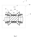
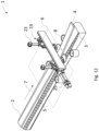
- Figure 1 shows a device 1 for separating a sawn timber package 2.
- the sawn timber package 2 comes from a tree trunk with an essentially circular cross-section.
- the tree trunk was processed in such a way that a single-stemmed beam was obtained from the inner cross-sectional area, which is referred to below as the main product 3.
- the sawn timber package 2 comes from the outer cross-sectional area of the tree trunk Boards obtained which are located on the top and bottom of the main product are referred to as side products 4.
- side products 4 For ease of understanding, reference is made below only to the side products 4 arranged above the main product 3.
- the main product 3 is separated from the side product 4 by a saw gap 5.
- the saw gap 5 lies in a horizontally running saw gap plane 6, which is shown as an aid.
- the sawn timber package 2 reaches the device 1, which comprises four separating means designed as conical rollers 9.
- the conical rollers 9 are arranged axially symmetrically to the sides of the sawn timber package 2 with respect to the feed direction 7. For better clarity, not all conical rollers 9 are provided with reference symbols.
- the conical rollers 9 are each designed in the shape of a truncated cone and each have a rotation axis 10 around which they are mounted so as to rotate freely. Furthermore, the conical rollers 9 each have a base surface 11 and a lateral surface 12, which enclose an acute angle of approximately 45° and are delimited by a circumferential separating edge 13.
- the conical rollers 9 are solid and made of steel and have a correspondingly high mechanical rigidity.
- the conical rollers serve to separate the side goods 4 from the main goods 3.
- a conical roller 9 with its circumferential separating edge 13 penetrates into the saw gap 5 of the sawn timber package 2.
- the side goods 4 slides transversely to the feed direction 7 on the base surfaces 10 of the conical rollers 9, while the main goods 3 rolls on the outer surfaces 12 and is conveyed further in the feed direction 7.
- the positions and orientations of the conical rollers 9 in relation to the sawn timber package 2 can be determined using the Figures 2 to 4 explained in detail.
- Figure 2 shows the Figure 1 shown device 1 in front view.
- the conical rollers 9 each have a circumferential surface 12 and a circumferential separating edge 13.
- the base surfaces of the conical rollers 9 shown are facing the image plane and are therefore not visible.
- the feed movement of the sawn timber package 2 takes place along the feed direction 7, which is Figure 2 directed from the image plane and oriented orthogonally to an inclination plane 14 shown as an aid.
- the conical rollers 9 are inclined with their respective rotation axes 10 and each enclose an acute inclination angle 15 in the inclination plane 14 with the saw gap plane 6.
- the angle of inclination 15 is selected depending on the geometry of the conical rollers 9 and corresponds to the acute angle between the base surface and the outer surface 12 of the conical rollers 9. This means that the main material 3 rests on or against a profile line of the outer surfaces 12 during the separation process and rolls over these on the conical rollers 9. In an alternative embodiment, the angle of inclination can be set smaller so that the main material 3 rolls over a point contact on the separating edges 13 of the conical rollers 9.
- Figure 3 shows the Figures 1 and 2 shown device 1 in plan view.
- the visible base surfaces 11 of the conical rollers 9 point out of the image plane, which runs parallel to the saw gap plane 6.
- the conical rollers 9 are also mounted in such a way that their respective rotation axes 10 in the saw gap plane 6 enclose an acute angle of attack 16 (also: camber) with the inclination plane 14.
- This arrangement results in the base surfaces 11 of the conical rollers 9 facing opposite to the feed direction 7 in accordance with the angle of attack 16.
- the base surfaces 11 each form a sliding plane for the side goods 3, on which the side goods 3 slides off the main goods 4.
- Figure 4 shows the Figures 1 to 3 shown device 1 in side view.
- the conical rollers 9 are mounted in such a way that their axes of rotation 10 enclose an acute tilt angle 18 in the image plane, which runs parallel to the tilt plane 17 shown as an alternative, and with the inclination plane 14.
- the Figures 1 to 4 The conical rollers 9 shown are mounted in an adjustable manner (not shown).
- the device 1 has a total of four positioning devices, one of which is in the Figures 5 to 8 shown in different views.
- Figure 5 shows a positioning device 19 with a holder 20 on which a conical roller 9 is mounted so as to be freely rotatable.
- the conical roller 9 has a bore along its axis of rotation 10 in which roller bearings are accommodated, which enable the conical roller 9 to rotate freely relative to the holder 20 and around the axis of rotation 10.
- a drive for the conical roller 9 can be arranged on the holder 20 in order to force it to rotate.
- the positioning device 19 also has a fastening element 21, which serves to fix the positioning device 19 in a fixed position, for example on a machine frame.
- the holder 20 is adjustably mounted relative to the fastening element 21 by means of a guide 22.
- a hydraulic linear actuator 23 is arranged between the holder 20 and the fastening element 21.
- the linear actuator 23 has an adjustment axis which corresponds to the guide axis of the guide 22.
- the positioning device 19 with the conical roller 9 arranged thereon is used in devices which are used to separate sawn timber with widely varying dimensions.
- its separating edge 13 is also adjusted and can thus be adapted to the position of a saw gap in a sawn timber package.
- Figure 6 shows the Figure 5 shown positioning device 19 in front view.
- the feed direction 7 of a sawn timber package to be separated points into the image plane.
- the conical roller 9 is inclined in such a way that the rotation axis 10 in the image plane encloses an acute angle of inclination 15 with the saw gap plane 6 shown here.
- the lower profile line on the outer surface 12 of the conical roller 8 runs essentially horizontally and thus parallel to the saw gap plane (not shown).
- the separating edge 13 penetrates into the saw gap of the sawn timber package in the manner already explained, with the conical roller 9 rolling on the main material in the area of the horizontally running profile line.
- the side material slides over the base surface 11 and is directed transversely to the feed direction 7 by the main material.
- Figure 7 shows the Figures 5 and 6 shown positioning device 19 in plan view. To better understand the intended installation position of the positioning device 19, the feed direction 7 of a sawn timber package is shown again.
- the conical roller 9 is inclined in such a way that its axis of rotation 10 in the image plane encloses an acute angle of attack 16 (also: camber) with the inclination plane 14 shown here as an alternative.
- Figure 8 shows the Figures 5 to 7 shown positioning device 19 in a side view.
- the conical roller 8 is inclined in such a way that its axis of rotation 10 in the image plane coincides with the inclination plane 14, as in relation to Figure 4 already explained, includes an acute tilt angle 17.
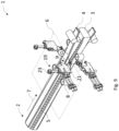
- Figure 9 shows the device 1 according to the Figures 1 to 4 , whose four conical rollers 9 are each mounted on a positioning device 19 according to the Figures 5 to 8 are stored.
- a positioning device 19 and the components arranged therein are provided with reference symbols.
- a camera system determines the structure and geometry of the sawn timber package 2 before the separation step and transmits the data obtained to an evaluation and Control unit.
- the recorded information contains both the external dimensions of the sawn timber package and the position, dimensions and course of the saw gap 6 within the sawn timber package 2. This information is used in the evaluation and control unit to control the linear actuators 23 in order to adjust the conical rollers 9 in such a way that their respective separating edges are adapted to the position of the saw gap 5.
- the dimensions of the sawn timber package and the position of the saw cuts can also be obtained from a cutting solution obtained mathematically based on an optical measurement of the tree trunk and/or a setting of the preceding sawing device resulting from this.
- the conveying device can also comprise a centering unit which is designed to adjust the sawn timber package 2 in the inclination plane 14 not shown here and to adapt the position of the saw gap 5 to the positions of the separating edges of the conical rollers 9.
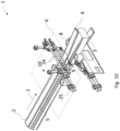
- Figure 10 shows a device 1 which has the same components as the one in Figure 9 In contrast to the device 1 shown in Figure 9
- the positioning devices 19, which are arranged in pairs above and below the sawn timber package 2 are mounted horizontally adjustable on a horizontally extending guide 24.
- a hydraulic linear actuator 25 is provided to move one of the positioning devices 19 and the conical rollers 9 mounted on it along the guide 24.
- the conical rollers 9 and the positions of their respective separating edges 13 can be adapted not only to a vertical position of the saw gap 5, but also to a width dimension of the sawn timber package 2.
- Figure 11 shows that in Figure 10 shown embodiment in a rear view.
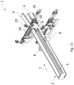
- the Figures 12 to 15 show a second embodiment of a device 1 for separating a sawn timber package 2 obtained from a trunk.
- This has essentially the same structure as the device shown in the Figures 10 and 11 shown device 1, but differs from this in the installation position of the conical rollers 9.
- the rotation axes of the conical rollers 9 run orthogonally through the saw gap plane 6.
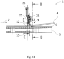
- Figure 13 shows the Figure 12 shown device 1 with one of the four conical rollers 9.
- the rotation axis 10 of the conical roller 9 runs orthogonal to the saw gap plane 6.
- the base surface of the conical roller 9 lies flat on the main product 3, while the side product 4 is rejected from the main product 3 via the outer surface 12.
- the rotation axis 10 can be tilted by a tilt angle in the image plane so that the base surface does not lie flat on the main product. Instead, the base surface forms an acute angle with the saw gap plane, which corresponds to the tilt angle and is open in the feed direction 7.
- Section BB corresponds to the representation in Figure 14
- section CC corresponds to the representation in Figure 15 .
- the sectional view shown shows the bearing of the conical rollers 9.
- the conical rollers each have a bore in the manner already described, in which roller bearings 26 are accommodated.
- the roller bearings serve to mount the conical rollers 9 so that they can rotate freely, with the rotation axes 10 running orthogonally to the saw gap plane 6.
- Figure 16 shows one of the Figures 10 to 15
- the positioning device 19 is essentially identical to the positioning device according to Figure 5
- the conical roller 9 shown is arranged such that the base surface of the holder 9 faces away and, in a provided installation position, faces the main product during the separation process.
Landscapes
- Life Sciences & Earth Sciences (AREA)
- Engineering & Computer Science (AREA)
- Wood Science & Technology (AREA)
- Forests & Forestry (AREA)
- Mechanical Engineering (AREA)
- Manufacturing & Machinery (AREA)
- Attitude Control For Articles On Conveyors (AREA)
- Rollers For Roller Conveyors For Transfer (AREA)
- Debarking, Splitting, And Disintegration Of Timber (AREA)
Applications Claiming Priority (1)
| Application Number | Priority Date | Filing Date | Title |
|---|---|---|---|
| DE102021128977.7A DE102021128977A1 (de) | 2021-11-08 | 2021-11-08 | Vorrichtung zum Separieren eines Schnittholzpaketes in Haupt- und Seitenware |
Publications (3)
| Publication Number | Publication Date |
|---|---|
| EP4177024A1 EP4177024A1 (de) | 2023-05-10 |
| EP4177024B1 true EP4177024B1 (de) | 2024-07-24 |
| EP4177024C0 EP4177024C0 (de) | 2024-07-24 |
Family
ID=84331941
Family Applications (1)
| Application Number | Title | Priority Date | Filing Date |
|---|---|---|---|
| EP22202516.5A Active EP4177024B1 (de) | 2021-11-08 | 2022-10-19 | Vorrichtung zum separieren eines schnittholzpaketes in haupt- und seitenware |
Country Status (6)
| Country | Link |
|---|---|
| US (1) | US12350856B2 (enExample) |
| EP (1) | EP4177024B1 (enExample) |
| JP (1) | JP2023075042A (enExample) |
| CA (1) | CA3181135A1 (enExample) |
| DE (1) | DE102021128977A1 (enExample) |
| PL (1) | PL4177024T3 (enExample) |
Families Citing this family (1)
| Publication number | Priority date | Publication date | Assignee | Title |
|---|---|---|---|---|
| DE102022132324A1 (de) | 2022-12-06 | 2024-06-06 | Gebrüder Linck, Maschinenfabrik "Gatterlinck" GmbH & Co. KG | Verfahren und Sägewerksvorrichtung zum Herstellen von Schnittholz aus einem Baumstamm |
Family Cites Families (12)
| Publication number | Priority date | Publication date | Assignee | Title |
|---|---|---|---|---|
| AT17009B (de) | 1903-11-07 | 1904-07-25 | Krupp Ag | Verfahren zur Herstellung kleinkalibriger ummantelter Stahlgeschosse. |
| US3313329A (en) * | 1965-11-10 | 1967-04-11 | Runnion Ernest E | Production of stud lumber from logs of small diameter |
| US3401785A (en) | 1967-01-30 | 1968-09-17 | Arthur M. Ferrari | Separator unit for lumber strips |
| US4166526A (en) | 1977-11-21 | 1979-09-04 | Morgan Construction Company | Apparatus for laterally arranging bars |
| DE3030602A1 (de) | 1980-08-13 | 1982-02-18 | Maschinenfabrik Esterer AG, 8262 Altötting | Vorrichtung zum trennen der seitenware von der hauptware bei nachschnittkreissaegen mit festem blatteinhang |
| DE3207548C2 (de) * | 1982-03-03 | 1984-02-23 | Gebrüder Linck Maschinenfabrik und Eisengießerei "Gatterlinck", 7602 Oberkirch | Vorrichtung zur Herstellung von flachen Holzerzeugnissen, wie Brettern |
| DE3343294A1 (de) * | 1983-11-30 | 1985-06-05 | Gebrüder Linck Maschinenfabrik und Eisengießerei "Gatterlinck", 7602 Oberkirch | Vorrichtung zur erzeugung von kantholz durch spanloses abtrennen von seitenbrettern |
| WO1988002683A1 (fr) | 1986-10-17 | 1988-04-21 | Wurster U. Dietz Gmbh U. Co. Maschinenfabrik | Procede et dispositif pour fendre ou refendre un produit de sciage rigide, notamment du bois |
| DE4035048A1 (de) * | 1990-11-05 | 1992-05-07 | Wurster & Dietz Maschf | Vorrichtung zum trennen oder schlitzen eines starren schnittgutes, insbesondere holz |
| DE4337682C1 (de) | 1993-11-04 | 1995-05-04 | Dietz Hans Prof Dr | Verfahren und Vorrichtung zum Zerlegen eines Baumstammes |
| FR2811605B1 (fr) | 2000-07-12 | 2002-10-11 | Georges Brun | Dispositif pour la separation de produits scies, en sortie d'une deligneuse |
| AT17009U1 (enExample) | 2020-01-31 | 2021-02-15 | Leitinger Hans Peter |
-
2021
- 2021-11-08 DE DE102021128977.7A patent/DE102021128977A1/de active Pending
-
2022
- 2022-10-19 PL PL22202516.5T patent/PL4177024T3/pl unknown
- 2022-10-19 EP EP22202516.5A patent/EP4177024B1/de active Active
- 2022-11-04 CA CA3181135A patent/CA3181135A1/en active Pending
- 2022-11-07 JP JP2022177979A patent/JP2023075042A/ja active Pending
- 2022-11-07 US US17/981,592 patent/US12350856B2/en active Active
Also Published As
| Publication number | Publication date |
|---|---|
| DE102021128977A1 (de) | 2023-05-11 |
| US12350856B2 (en) | 2025-07-08 |
| EP4177024A1 (de) | 2023-05-10 |
| JP2023075042A (ja) | 2023-05-30 |
| CA3181135A1 (en) | 2023-05-08 |
| US20230146108A1 (en) | 2023-05-11 |
| EP4177024C0 (de) | 2024-07-24 |
| PL4177024T3 (pl) | 2024-10-21 |
Similar Documents
| Publication | Publication Date | Title |
|---|---|---|
| DE3720169C2 (enExample) | ||
| DE3311390A1 (de) | Verfahren und vorrichtung zum ermitteln des auf ein bandsaegeblatt einwirkenden schneidwiderstandes | |
| DE69315337T2 (de) | Maschine zum schneiden von bogen aus einer papierbahn und zum gleichzeitigen schneiden eines querstreifens | |
| DE19740222A1 (de) | Vorrichtung zum Führen einer Endlospapierbahn | |
| EP4177024B1 (de) | Vorrichtung zum separieren eines schnittholzpaketes in haupt- und seitenware | |
| WO2001091980A1 (de) | Vorrichtung zum aufschneiden von lebensmittelprodukten | |
| EP0438736B1 (de) | Vorrichtung zum Schneiden von gestapeltem, blattförmigem Gut mit einem Frontaufstosser zum Ausrichten des Gutes an einer Vorschubeinheit | |
| EP3733365A1 (de) | Vorrichtung zum schneiden eines lebensmittels in streifen oder würfel und verfahren zum demontieren einer doppel-gattereinrichtung | |
| EP3896018B1 (de) | Verfahren und vorrichtung zum positionsgenauen zuführen von flächenförmigen blechtafeln zu einem bearbeitungsprozess beziehungsweise einer bearbeitungseinheit | |
| EP2802441B1 (de) | Holzbearbeitungsanlage und verfahren zu deren betrieb | |
| DE2413198A1 (de) | Schneidvorrichtung | |
| DE102013206159A1 (de) | Plattenaufteilanlage | |
| EP1184121B1 (de) | Verfahren und Vorrichtung zum Vermessen und Korrigieren des Spannungsprofils von Sägeblättern | |
| DE9013814U1 (de) | Vorrichtung zum Abnehmen und Abtransportieren einer Platte | |
| DE102023123878A1 (de) | Aufschneide-Maschine, insbesondere Slicer, sowie Verfahren | |
| DE8417560U1 (de) | Parallelhobelmaschine | |
| DE202023100126U1 (de) | Schneidmessereinheit | |
| EP1218271B1 (de) | Vorrichtung zum drehen eines papierstapels | |
| EP0604702B1 (de) | Vorrichtung zum schneidenden Abtrennen dünner Bretter von Kanthölzern | |
| EP0190665A1 (de) | Maschine zum Bearbeiten von Furnierblättern | |
| DE29520112U1 (de) | Vorrichtung zum Trennen und seitlichem Auslenken durch Längsschnitt erzeugten Metallstreifen | |
| EP1889698A1 (de) | Seitenware-Abscheidevorrichtung | |
| DE3219046C2 (enExample) | ||
| EP3812313B1 (de) | Plattentransportvorrichtung | |
| DE102009017525B3 (de) | Holzhacker |
Legal Events
| Date | Code | Title | Description |
|---|---|---|---|
| PUAI | Public reference made under article 153(3) epc to a published international application that has entered the european phase |
Free format text: ORIGINAL CODE: 0009012 |
|
| STAA | Information on the status of an ep patent application or granted ep patent |
Free format text: STATUS: THE APPLICATION HAS BEEN PUBLISHED |
|
| AK | Designated contracting states |
Kind code of ref document: A1 Designated state(s): AL AT BE BG CH CY CZ DE DK EE ES FI FR GB GR HR HU IE IS IT LI LT LU LV MC ME MK MT NL NO PL PT RO RS SE SI SK SM TR |
|
| STAA | Information on the status of an ep patent application or granted ep patent |
Free format text: STATUS: REQUEST FOR EXAMINATION WAS MADE |
|
| 17P | Request for examination filed |
Effective date: 20230810 |
|
| RBV | Designated contracting states (corrected) |
Designated state(s): AL AT BE BG CH CY CZ DE DK EE ES FI FR GB GR HR HU IE IS IT LI LT LU LV MC ME MK MT NL NO PL PT RO RS SE SI SK SM TR |
|
| RIC1 | Information provided on ipc code assigned before grant |
Ipc: B27B 15/02 20060101ALN20231130BHEP Ipc: B27L 5/00 20060101ALI20231130BHEP Ipc: B27G 19/08 20060101ALI20231130BHEP Ipc: B27B 31/08 20060101AFI20231130BHEP |
|
| GRAP | Despatch of communication of intention to grant a patent |
Free format text: ORIGINAL CODE: EPIDOSNIGR1 |
|
| STAA | Information on the status of an ep patent application or granted ep patent |
Free format text: STATUS: GRANT OF PATENT IS INTENDED |
|
| INTG | Intention to grant announced |
Effective date: 20240117 |
|
| GRAS | Grant fee paid |
Free format text: ORIGINAL CODE: EPIDOSNIGR3 |
|
| GRAJ | Information related to disapproval of communication of intention to grant by the applicant or resumption of examination proceedings by the epo deleted |
Free format text: ORIGINAL CODE: EPIDOSDIGR1 |
|
| GRAL | Information related to payment of fee for publishing/printing deleted |
Free format text: ORIGINAL CODE: EPIDOSDIGR3 |
|
| STAA | Information on the status of an ep patent application or granted ep patent |
Free format text: STATUS: REQUEST FOR EXAMINATION WAS MADE |
|
| GRAP | Despatch of communication of intention to grant a patent |
Free format text: ORIGINAL CODE: EPIDOSNIGR1 |
|
| STAA | Information on the status of an ep patent application or granted ep patent |
Free format text: STATUS: GRANT OF PATENT IS INTENDED |
|
| INTC | Intention to grant announced (deleted) | ||
| RIC1 | Information provided on ipc code assigned before grant |
Ipc: B27B 15/02 20060101ALN20240513BHEP Ipc: B27L 5/00 20060101ALI20240513BHEP Ipc: B27G 19/08 20060101ALI20240513BHEP Ipc: B27B 31/08 20060101AFI20240513BHEP |
|
| GRAA | (expected) grant |
Free format text: ORIGINAL CODE: 0009210 |
|
| STAA | Information on the status of an ep patent application or granted ep patent |
Free format text: STATUS: THE PATENT HAS BEEN GRANTED |
|
| INTG | Intention to grant announced |
Effective date: 20240605 |
|
| AK | Designated contracting states |
Kind code of ref document: B1 Designated state(s): AL AT BE BG CH CY CZ DE DK EE ES FI FR GB GR HR HU IE IS IT LI LT LU LV MC ME MK MT NL NO PL PT RO RS SE SI SK SM TR |
|
| REG | Reference to a national code |
Ref country code: GB Ref legal event code: FG4D Free format text: NOT ENGLISH |
|
| REG | Reference to a national code |
Ref country code: CH Ref legal event code: EP |
|
| REG | Reference to a national code |
Ref country code: DE Ref legal event code: R096 Ref document number: 502022001299 Country of ref document: DE |
|
| REG | Reference to a national code |
Ref country code: IE Ref legal event code: FG4D Free format text: LANGUAGE OF EP DOCUMENT: GERMAN |
|
| U01 | Request for unitary effect filed |
Effective date: 20240724 |
|
| U07 | Unitary effect registered |
Designated state(s): AT BE BG DE DK EE FI FR IT LT LU LV MT NL PT SE SI Effective date: 20240731 |
|
| U20 | Renewal fee for the european patent with unitary effect paid |
Year of fee payment: 3 Effective date: 20240925 |
|
| PGFP | Annual fee paid to national office [announced via postgrant information from national office to epo] |
Ref country code: NO Payment date: 20241022 Year of fee payment: 3 |
|
| PG25 | Lapsed in a contracting state [announced via postgrant information from national office to epo] |
Ref country code: GR Free format text: LAPSE BECAUSE OF FAILURE TO SUBMIT A TRANSLATION OF THE DESCRIPTION OR TO PAY THE FEE WITHIN THE PRESCRIBED TIME-LIMIT Effective date: 20241025 |
|
| PGFP | Annual fee paid to national office [announced via postgrant information from national office to epo] |
Ref country code: PL Payment date: 20241014 Year of fee payment: 3 |
|
| PG25 | Lapsed in a contracting state [announced via postgrant information from national office to epo] |
Ref country code: IS Free format text: LAPSE BECAUSE OF FAILURE TO SUBMIT A TRANSLATION OF THE DESCRIPTION OR TO PAY THE FEE WITHIN THE PRESCRIBED TIME-LIMIT Effective date: 20241124 |
|
| PG25 | Lapsed in a contracting state [announced via postgrant information from national office to epo] |
Ref country code: HR Free format text: LAPSE BECAUSE OF FAILURE TO SUBMIT A TRANSLATION OF THE DESCRIPTION OR TO PAY THE FEE WITHIN THE PRESCRIBED TIME-LIMIT Effective date: 20240724 |
|
| PG25 | Lapsed in a contracting state [announced via postgrant information from national office to epo] |
Ref country code: RS Free format text: LAPSE BECAUSE OF FAILURE TO SUBMIT A TRANSLATION OF THE DESCRIPTION OR TO PAY THE FEE WITHIN THE PRESCRIBED TIME-LIMIT Effective date: 20241024 Ref country code: ES Free format text: LAPSE BECAUSE OF FAILURE TO SUBMIT A TRANSLATION OF THE DESCRIPTION OR TO PAY THE FEE WITHIN THE PRESCRIBED TIME-LIMIT Effective date: 20240724 |
|
| PG25 | Lapsed in a contracting state [announced via postgrant information from national office to epo] |
Ref country code: RS Free format text: LAPSE BECAUSE OF FAILURE TO SUBMIT A TRANSLATION OF THE DESCRIPTION OR TO PAY THE FEE WITHIN THE PRESCRIBED TIME-LIMIT Effective date: 20241024 Ref country code: IS Free format text: LAPSE BECAUSE OF FAILURE TO SUBMIT A TRANSLATION OF THE DESCRIPTION OR TO PAY THE FEE WITHIN THE PRESCRIBED TIME-LIMIT Effective date: 20241124 Ref country code: HR Free format text: LAPSE BECAUSE OF FAILURE TO SUBMIT A TRANSLATION OF THE DESCRIPTION OR TO PAY THE FEE WITHIN THE PRESCRIBED TIME-LIMIT Effective date: 20240724 Ref country code: GR Free format text: LAPSE BECAUSE OF FAILURE TO SUBMIT A TRANSLATION OF THE DESCRIPTION OR TO PAY THE FEE WITHIN THE PRESCRIBED TIME-LIMIT Effective date: 20241025 Ref country code: ES Free format text: LAPSE BECAUSE OF FAILURE TO SUBMIT A TRANSLATION OF THE DESCRIPTION OR TO PAY THE FEE WITHIN THE PRESCRIBED TIME-LIMIT Effective date: 20240724 |
|
| PG25 | Lapsed in a contracting state [announced via postgrant information from national office to epo] |
Ref country code: SM Free format text: LAPSE BECAUSE OF FAILURE TO SUBMIT A TRANSLATION OF THE DESCRIPTION OR TO PAY THE FEE WITHIN THE PRESCRIBED TIME-LIMIT Effective date: 20240724 Ref country code: RO Free format text: LAPSE BECAUSE OF FAILURE TO SUBMIT A TRANSLATION OF THE DESCRIPTION OR TO PAY THE FEE WITHIN THE PRESCRIBED TIME-LIMIT Effective date: 20240724 |
|
| PG25 | Lapsed in a contracting state [announced via postgrant information from national office to epo] |
Ref country code: CZ Free format text: LAPSE BECAUSE OF FAILURE TO SUBMIT A TRANSLATION OF THE DESCRIPTION OR TO PAY THE FEE WITHIN THE PRESCRIBED TIME-LIMIT Effective date: 20240724 |
|
| PG25 | Lapsed in a contracting state [announced via postgrant information from national office to epo] |
Ref country code: SK Free format text: LAPSE BECAUSE OF FAILURE TO SUBMIT A TRANSLATION OF THE DESCRIPTION OR TO PAY THE FEE WITHIN THE PRESCRIBED TIME-LIMIT Effective date: 20240724 |
|
| PLBE | No opposition filed within time limit |
Free format text: ORIGINAL CODE: 0009261 |
|
| STAA | Information on the status of an ep patent application or granted ep patent |
Free format text: STATUS: NO OPPOSITION FILED WITHIN TIME LIMIT |
|
| 26N | No opposition filed |
Effective date: 20250425 |
|
| PG25 | Lapsed in a contracting state [announced via postgrant information from national office to epo] |
Ref country code: MC Free format text: LAPSE BECAUSE OF FAILURE TO SUBMIT A TRANSLATION OF THE DESCRIPTION OR TO PAY THE FEE WITHIN THE PRESCRIBED TIME-LIMIT Effective date: 20240724 |
|
| U20 | Renewal fee for the european patent with unitary effect paid |
Year of fee payment: 4 Effective date: 20250827 |
|
| PG25 | Lapsed in a contracting state [announced via postgrant information from national office to epo] |
Ref country code: IE Free format text: LAPSE BECAUSE OF NON-PAYMENT OF DUE FEES Effective date: 20241019 |