EP4176170B1 - Gasinjektor mit reduziertem verschleiss - Google Patents
Gasinjektor mit reduziertem verschleiss Download PDFInfo
- Publication number
- EP4176170B1 EP4176170B1 EP21719867.0A EP21719867A EP4176170B1 EP 4176170 B1 EP4176170 B1 EP 4176170B1 EP 21719867 A EP21719867 A EP 21719867A EP 4176170 B1 EP4176170 B1 EP 4176170B1
- Authority
- EP
- European Patent Office
- Prior art keywords
- gas injector
- brake
- gas
- armature
- lubricant
- Prior art date
- Legal status (The legal status is an assumption and is not a legal conclusion. Google has not performed a legal analysis and makes no representation as to the accuracy of the status listed.)
- Active
Links
Images


Classifications
-
- F—MECHANICAL ENGINEERING; LIGHTING; HEATING; WEAPONS; BLASTING
- F02—COMBUSTION ENGINES; HOT-GAS OR COMBUSTION-PRODUCT ENGINE PLANTS
- F02M—SUPPLYING COMBUSTION ENGINES IN GENERAL WITH COMBUSTIBLE MIXTURES OR CONSTITUENTS THEREOF
- F02M21/00—Apparatus for supplying engines with non-liquid fuels, e.g. gaseous fuels stored in liquid form
- F02M21/02—Apparatus for supplying engines with non-liquid fuels, e.g. gaseous fuels stored in liquid form for gaseous fuels
- F02M21/0218—Details on the gaseous fuel supply system, e.g. tanks, valves, pipes, pumps, rails, injectors or mixers
- F02M21/0248—Injectors
- F02M21/0251—Details of actuators therefor
- F02M21/0254—Electric actuators, e.g. solenoid or piezoelectric
-
- F—MECHANICAL ENGINEERING; LIGHTING; HEATING; WEAPONS; BLASTING
- F02—COMBUSTION ENGINES; HOT-GAS OR COMBUSTION-PRODUCT ENGINE PLANTS
- F02M—SUPPLYING COMBUSTION ENGINES IN GENERAL WITH COMBUSTIBLE MIXTURES OR CONSTITUENTS THEREOF
- F02M21/00—Apparatus for supplying engines with non-liquid fuels, e.g. gaseous fuels stored in liquid form
- F02M21/02—Apparatus for supplying engines with non-liquid fuels, e.g. gaseous fuels stored in liquid form for gaseous fuels
- F02M21/0218—Details on the gaseous fuel supply system, e.g. tanks, valves, pipes, pumps, rails, injectors or mixers
- F02M21/0248—Injectors
- F02M21/0257—Details of the valve closing elements, e.g. valve seats, stems or arrangement of flow passages
-
- F—MECHANICAL ENGINEERING; LIGHTING; HEATING; WEAPONS; BLASTING
- F02—COMBUSTION ENGINES; HOT-GAS OR COMBUSTION-PRODUCT ENGINE PLANTS
- F02M—SUPPLYING COMBUSTION ENGINES IN GENERAL WITH COMBUSTIBLE MIXTURES OR CONSTITUENTS THEREOF
- F02M61/00—Fuel-injectors not provided for in groups F02M39/00 - F02M57/00 or F02M67/00
- F02M61/04—Fuel-injectors not provided for in groups F02M39/00 - F02M57/00 or F02M67/00 having valves, e.g. having a plurality of valves in series
- F02M61/08—Fuel-injectors not provided for in groups F02M39/00 - F02M57/00 or F02M67/00 having valves, e.g. having a plurality of valves in series the valves opening in direction of fuel flow
-
- F—MECHANICAL ENGINEERING; LIGHTING; HEATING; WEAPONS; BLASTING
- F02—COMBUSTION ENGINES; HOT-GAS OR COMBUSTION-PRODUCT ENGINE PLANTS
- F02M—SUPPLYING COMBUSTION ENGINES IN GENERAL WITH COMBUSTIBLE MIXTURES OR CONSTITUENTS THEREOF
- F02M61/00—Fuel-injectors not provided for in groups F02M39/00 - F02M57/00 or F02M67/00
- F02M61/04—Fuel-injectors not provided for in groups F02M39/00 - F02M57/00 or F02M67/00 having valves, e.g. having a plurality of valves in series
- F02M61/10—Other injectors with elongated valve bodies, i.e. of needle-valve type
- F02M61/12—Other injectors with elongated valve bodies, i.e. of needle-valve type characterised by the provision of guiding or centring means for valve bodies
-
- F—MECHANICAL ENGINEERING; LIGHTING; HEATING; WEAPONS; BLASTING
- F02—COMBUSTION ENGINES; HOT-GAS OR COMBUSTION-PRODUCT ENGINE PLANTS
- F02M—SUPPLYING COMBUSTION ENGINES IN GENERAL WITH COMBUSTIBLE MIXTURES OR CONSTITUENTS THEREOF
- F02M2200/00—Details of fuel-injection apparatus, not otherwise provided for
- F02M2200/07—Fuel-injection apparatus having means for avoiding sticking of valve or armature, e.g. preventing hydraulic or magnetic sticking of parts
-
- F—MECHANICAL ENGINEERING; LIGHTING; HEATING; WEAPONS; BLASTING
- F02—COMBUSTION ENGINES; HOT-GAS OR COMBUSTION-PRODUCT ENGINE PLANTS
- F02M—SUPPLYING COMBUSTION ENGINES IN GENERAL WITH COMBUSTIBLE MIXTURES OR CONSTITUENTS THEREOF
- F02M2200/00—Details of fuel-injection apparatus, not otherwise provided for
- F02M2200/70—Linkage between actuator and actuated element, e.g. between piezoelectric actuator and needle valve or pump plunger
- F02M2200/703—Linkage between actuator and actuated element, e.g. between piezoelectric actuator and needle valve or pump plunger hydraulic
- F02M2200/707—Linkage between actuator and actuated element, e.g. between piezoelectric actuator and needle valve or pump plunger hydraulic with means for avoiding fuel contact with actuators, e.g. isolating actuators by using bellows or diaphragms
-
- Y—GENERAL TAGGING OF NEW TECHNOLOGICAL DEVELOPMENTS; GENERAL TAGGING OF CROSS-SECTIONAL TECHNOLOGIES SPANNING OVER SEVERAL SECTIONS OF THE IPC; TECHNICAL SUBJECTS COVERED BY FORMER USPC CROSS-REFERENCE ART COLLECTIONS [XRACs] AND DIGESTS
- Y02—TECHNOLOGIES OR APPLICATIONS FOR MITIGATION OR ADAPTATION AGAINST CLIMATE CHANGE
- Y02T—CLIMATE CHANGE MITIGATION TECHNOLOGIES RELATED TO TRANSPORTATION
- Y02T10/00—Road transport of goods or passengers
- Y02T10/10—Internal combustion engine [ICE] based vehicles
- Y02T10/30—Use of alternative fuels, e.g. biofuels
Definitions
- the present invention relates to a gas injector for injecting a gaseous fuel, in particular hydrogen or natural gas or the like, with reduced wear, in particular for internal combustion engines.
- the gas injector is designed in particular for direct injection into a combustion chamber of an internal combustion engine.
- Gas injectors are known from the state of the art in various designs, such as EN 102008041544 A1 .
- gas injectors due to the gaseous medium being injected, lubrication by the medium is not possible, as is the case with fuel injectors that inject petrol or diesel, for example. This results in excessive wear during operation compared to fuel injectors for liquid fuels. In this case, it would be desirable to have a gas injector with improved wear behavior.
- the gas injector according to the invention for injecting a gaseous fuel with the features of claim 1 has the advantage that wear of the gas injector can be significantly reduced. This extends the service life of the gas injector and essentially corresponds to the service life of a fuel injector for liquid fuels. This is achieved according to the invention in that the gas injector has a lubricant located in a closed lubricant chamber in which movable parts of the gas injector are arranged.
- the gas injector comprises a magnetic actuator with an armature, an inner pole and a coil.
- the armature which is mechanically connected to a closing element that opens and closes a gas path on a valve seat, is connected to enable a movement to open and/or close the injector.
- the armature located in the lubricant chamber which is pulled against the inner pole of the magnetic actuator due to electromagnetic forces when the coil is energized, is therefore located inside the lubricant chamber and is constantly supplied with lubricant and lubricated. This significantly reduces wear on the armature compared to the gas injectors known from the state of the art.
- a flexible sealing element is provided which seals the lubricant chamber in a partial area against the closing element. The service life of the gas injector can thus be significantly extended by using the closed lubricant chamber filled with lubricant.
- the lubricant chamber is preferably completely filled with lubricant.
- a braking device is arranged in the lubricant chamber, which is designed to brake the closing element during a resetting process of the closing element. This can reduce wear on the valve seat, since braking the closing element during the resetting process can reduce the impact of the closing element on the valve body seat.
- the braking device can reduce the impulse when the closing element hits the valve body, especially since the valve seat is usually very dry and sits in the hot combustion chamber atmosphere.
- the braking device comprises a brake bolt and an elastic braking element, for example a spring or an elastic component.
- the closing element is a valve needle which is designed separately from the brake bolt, and the brake bolt can be brought into operative connection with the armature and/or the closing element during the resetting process, so that the armature hits the brake bolt before it actually hits the stop and moves it against the force of the elastic element, which makes it possible to dampen the armature during the resetting process.
- the resetting speed of the armature is reduced. This is additionally achieved by the acceleration provided by the braking device of the additional masses. Furthermore, further braking is achieved by displacing the lubricant between the armature and the brake bolt.
- the return speed of the locking element can also be further reduced by friction between guide elements or the like and the brake bolt. All of this reduces the impact force of the armature on the stop, so that the service life of the armature can be further extended.
- a brake guide element is arranged on the brake bolt, which ensures a stable movement of the guide bolt. Furthermore, the brake guide element can also generate friction during the return process of the locking element, which additionally provides a damping function.
- an axial gap B between the brake guide element and the brake bolt is smaller than an axial gap C between the armature and the inner pole.
- the axial gap B between the brake guide element and the brake bolt is in a range from 1% to 90% of the axial gap C between the armature and the inner pole.
- the axial gap B between the brake guide element and the brake bolt is smaller than 25% of the axial gap C, more preferably in a range from 3% to 10% of the axial gap C.
- the axial gap C preferably has a size of 0.05 mm to 3 mm, in particular 0.3 mm.
- an oil especially mineral oil
- a liquid fuel especially diesel or petrol
- a grease is used as the lubricant.
- the flexible sealing element is also preferably a single-layer or multi-layer bellows.
- the bellows is preferably made of metal or alternatively of a plastic.
- the bellows is preferably fixed with a first end directly to the closing element and with another end to a housing component of the gas injector. The fixing can be done, for example, with metal bellows by means of a weld seam.
- the flexible sealing element is a membrane.
- the membrane can be single-layered or multi-layered and can be fixed to the respective components to seal the lubricant chamber, for example by means of laser welding.
- a gas path of the gaseous fuel is provided in a region between a valve housing of the gas injector and an actuator housing of the gas injector. This allows the actuator to be arranged in a housing and at least partially pre-assembled as an assembly. This also allows the lubricant chamber to be arranged inside the actuator housing in a relatively simple manner.
- the gas path of the gaseous fuel is formed through a region of the magnetic actuator, in particular through the coil space in which the coil of the magnetic actuator is arranged.
- a separate actuator housing for the magnetic actuator is not required.
- an electrical contact is made through the gas path of the gaseous fuel. This makes it possible to reduce the complexity of the structure of the gas injector in particular. It should be noted that the electrical contact, which runs through the gas space, must of course be sealed from the outside.
- a filter is arranged in the gas path for the gaseous fuel in order to filter out any solid particles that may be present in the gaseous fuel or to filter out solid particles that are caused by manufacturing or assembly. It is also preferred that a guide component is provided on the closing element, in particular if the closing element is a long valve needle.
- the gas injector is preferably an injector that opens outwards.
- the gas injector is also preferably pressure balanced. This means that the force for opening the gas injector by the magnetic actuator is independent of the gas pressure.
- the time for opening and closing the injector after the start or end of the current supply is therefore also independent of the gas pressure. This in turn allows operation at different gas pressures. If a small injection quantity is required, the gas pressure can be reduced and if a large injection quantity is required, the gas pressure can be increased.
- the injector is pressure balanced if the average diameter of the bellows is equal to the diameter of the seat contact line between the closing element and the valve body. The average bellows diameter can also be smaller or larger than the seat diameter.
- the pressure is reduced with a higher Gas pressure exerts the entire closing force on the valve needle and the injector opens faster when energized and closes more slowly after energization. This results in an increased gas injection quantity.
- the closing force on the valve needle increases with a higher gas pressure. This in turn can compensate for an increase in the seat leakage quantity due to the higher gas pressure.
- a reset is preferably carried out by means of a return spring.
- a pressure-balanced injector there is in particular no pressure force on the valve needle from the gaseous fuel when the gas injector is closed, so that the load on the closing element can be significantly reduced.
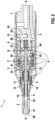
- the gas injector 1 for introducing a gaseous fuel comprises a magnetic actuator 2, which has a closing element 3 in In this embodiment, an outward opening valve needle is moved from a closed state to an open state.
- the Figures 1 to 3 show the closed state of the gas injector.
- the magnetic actuator 2 comprises an armature 20, which rests on the closing element 3 by means of an armature bolt 24.
- the magnetic actuator 2 further comprises an inner pole 21, a coil 22 and a magnet housing 23, which ensures a magnetic return of the magnetic actuator.
- the gas injector 1 also comprises a main body 7 with a connecting pipe 70 through which the gaseous fuel is supplied.
- a valve housing 8 is fixed to the main body 7, in which the magnetic actuator 2 is arranged.
- a valve body 9 is connected to the valve housing 8, at the free end of which a valve seat 90 is provided, in which the closing element 3 opens and closes a passage for the gaseous fuel.
- a holding body 12 is provided to fix the inner pole 21 to the valve body 9.
- the reference number 10 designates a return element for the closing element 3 in order to return it to the position shown in Figure 1 to return to the closed state shown.
- a gas flow is also shown as a gas path 14 through the gas injector 1.
- the gas flow begins at the connection pipe and is then diverted by 90° into an annular space 80 between the valve housing 8 and the main body 7.
- the gas flow 14 continues past an outer region of the magnetic actuator 2 through a filter 11 in the area of the closing element 3 up to the valve seat 90.
- Corresponding openings are provided in the respective components, which are not shown in the figures.
- the closing element 3 thus releases a gas path at the valve seat 90 and closes it.
- a first guide area 31 and a second guide area 32 are provided between the closing element 3 and the valve body 9, as shown in detail in Figure 2 is evident.
- the gas injector 1 comprises a closed lubricant chamber 4.
- the lubricant chamber 4 is shown in detail in the Figures 2 and 3
- the closed lubricant chamber 4 is completely or partially filled with a lubricant.
- the lubricant chamber 4 is closed off by the main body 7, the magnet housing 23, the inner pole 21 and a flexible sealing element 5 in the form of a bellows.
- the flexible sealing element 5 seals off the closing element 3.
- the flexible sealing element 5 is thus fixed with a first end to a spring plate 16, which supports a return element 10 for the closing element 3 and with a second end to a sleeve-shaped ring 15.
- the flexible sealing element 5 compensates for the movement of the closing element 3 occurring in the axial direction XX of the injector.
- the anchor bolt 24 is arranged with the anchor 20 fixed to it. Since the lubricant chamber 4 is filled with a lubricant, for example a liquid fuel such as petrol or diesel or a grease or the like, the anchor 20 is continuously lubricated. This can compensate for the problem that occurs in the prior art with gaseous fuels, namely a lack of lubrication of the moving parts.
- a lubricant for example a liquid fuel such as petrol or diesel or a grease or the like
- a filling channel 63 is formed in the main body 7 for filling the closed lubricant chamber 4.
- the filling channel 63 is closed fluid-tight by means of a closure ball 64.
- a braking device 6 is also arranged in the closed lubricant chamber 4.
- the braking device 6 comprises a brake bolt 60, a brake spring 61 and a brake guide element 62.
- the brake guide element 62 serves to guide the brake bolt 60 and is arranged on an inner circumference of the magnet housing 23 (cf. Figures 2 and 3 ).
- the brake bolt 60 is operatively connected to the anchor via the anchor bolt 24.
- the braking device 6 has the task of braking the closing element 3 together with the armature 20 during a closing process of the gas injector 1.
- the braking takes place on the one hand via the brake spring force by the brake spring 61 on the brake bolt 60 and a hydraulic bonding on an axial contact surface 65 between the brake bolt 60 and the fixed brake guide element 62 (cf. Figure 3 ) when the brake bolt 60 is lifted from the axial contact surface 65.
- the closing element 3 when the closing element 3 is reset, it is braked by the friction in the brake guide element 62, into which the anchor bolt 24 also partially protrudes. Furthermore, the accelerated masses and the displacement of the lubricant in the closed lubricant chamber 4 lead to additional braking during the closing process.
- an axial gap C is provided between the armature 20 and the inner pole 21.
- An axial gap B is provided between the brake bolt 60 and the brake guide element 62.
- the axial gap C between the armature 20 and the inner pole 21 is preferably in a range of 0.05 to 3 mm and is particularly preferably 0.2 mm to 0.5 mm.
- the armature 20 is then pulled against the inner pole 21, whereby the closing element 3 is brought into the open state via the armature bolt 24 so that gaseous fuel can flow out into the combustion chamber.
- the armature bolt 24 and/or the sleeve-shaped ring 15 are made of non-magnetizable materials.
- the axial gap B between the brake bolt 60 and the brake guide element 62 is smaller than the gap C between the armature 20 and the inner pole 21 and is also closed during the opening process by the spring force of the brake spring 61.
- the gap B is preferably 1% to 90% of the gap C. This ensures that the brake bolt 60 is hydraulically bonded to the brake guide element 62 during the resetting process.
- the gas injector 1 shown is pressure balanced.
- the closing element 3 is connected to the flexible sealing element 5 via the spring plate 16, wherein the flexible sealing element 5 designed as a metal bellows has an average diameter D1 which is equal to a diameter D2 on the valve seat 90 at which the closing element 3 seals on the valve body 9.
- D1 the average diameter
- D2 the diameter of the valve seat 90
- the flexible sealing element 5 can also be, for example, a membrane or a hose or the like instead of the bellows.
- the gas injector 1 can thus provide reduced wear on the moving parts, in particular on the valve seat 90, armature 20 and in the armature bolt 24. Furthermore, heat dissipation from the magnetic actuator 2 can be significantly improved by the sealed lubricant chamber 4 with a liquid lubricant.
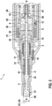
- Figure 4 shows a gas injector 1 according to a second embodiment of the invention. The same or functionally identical parts are designated as in the first embodiment.
- the structure of the gas injector 1 is basically the same as that of the first embodiment.
- a gas path 14 in the area of the magnetic actuator 2 is guided differently.
- the gas path 14 goes through the coil space on the magnetic actuator 2, in which the coil 22 is arranged.
- the gas path 14 leads through openings in the magnet pot 25.
- the electrical connection 13 in the form of a Contact pins are insulated from the main body 7.
- a first guide region 31 of the closing element 3 is provided on an outer circumference of the spring plate 16.
- the spring plate 16 has corresponding passage openings for the gas path 14.
- the lubricant chamber 4 is encapsulated according to the first embodiment and provides lubrication of the armature 20 during opening and closing processes of the gas injector 1.
- this embodiment corresponds to the first embodiment, so that reference can be made to the description given there.
Landscapes
- Engineering & Computer Science (AREA)
- Chemical & Material Sciences (AREA)
- Combustion & Propulsion (AREA)
- Mechanical Engineering (AREA)
- General Engineering & Computer Science (AREA)
- Chemical Kinetics & Catalysis (AREA)
- General Chemical & Material Sciences (AREA)
- Oil, Petroleum & Natural Gas (AREA)
- Analytical Chemistry (AREA)
- Fuel-Injection Apparatus (AREA)
- Magnetically Actuated Valves (AREA)
Description
- Die vorliegende Erfindung betrifft einen Gasinjektor zum Einblasen eines gasförmigen Brennstoffs, insbesondere Wasserstoff oder Erdgas oder dergleichen mit einem reduzierten Verschleiß insbesondere für Brennkraftmaschinen. Der Gasinjektor ist insbesondere für eine Direkteinblasung in einen Brennraum einer Brennkraftmaschine ausgelegt.
- Gasinjektoren sind aus dem Stand der Technik in unterschiedlichen Ausgestaltungen bekannt, wie z.B. aus
DE 102008041544 A1 . - Ein Problemkreis bei Gasinjektoren liegt prinzipbedingt darin, dass aufgrund des gasförmigen, einzublasenden Mediums keine Schmierung durch das Medium möglich ist, wie dies beispielsweise bei Kraftstoffinjektoren, welche Benzin oder Diesel einspritzen, möglich ist. Daraus resultiert im Betrieb ein übermäßiger Verschleiß im Vergleich mit Kraftstoffinjektoren für flüssige Kraftstoffe. Hierbei wäre es wünschenswert, einen Gasinjektor mit einem verbesserten Verschleißverhalten zu haben.
- Der erfindungsgemäße Gasinjektor zum Einblasen eines gasförmigen Brennstoffs mit den Merkmalen des Anspruchs 1 weist hiergegen den Vorteil auf, dass ein Verschleiß des Gasinjektors signifikant reduziert werden kann. Dadurch wird eine Lebensdauer des Gasinjektors verlängert und entspricht im Wesentlichen einer Lebensdauer eines Kraftstoffinjektors für flüssige Kraftstoffe. Dies wird erfindungsgemäß dadurch erreicht, dass der Gasinjektor ein in einem abgeschlossenen Schmiermittelraum befindliches Schmiermittel aufweist, in welchem bewegliche Teile des Gasinjektors angeordnet sind. Der Gasinjektor umfasst einen Magnetaktor mit einem Anker, einem Innenpol und einer Spule.
- Hierbei ist der Anker, welcher mit einem Schließelement, das einen Gaspfad an einem Ventilsitz freigibt und verschließt, mechanisch verbunden, um eine Bewegung zum Öffnen und/oder Schließen des Injektors zu ermöglichen. Der im Schmiermittelraum befindliche Anker, welcher bei einer Bestromung der Spule gegen den Innenpol des Magnetaktors aufgrund elektromagnetischer Kräfte gezogen wird, befindet sich somit im Inneren des Schmiermittelraums und wird ständig mit Schmiermittel versorgt und geschmiert. Dadurch ist ein Verschleiß am Anker im Vergleich mit den bisher aus dem Stand der Technik bekannten Gasinjektoren signifikant reduziert. Um eine Abdichtung des Schmiermittelraums sicherzustellen, ist ein flexibles Dichtelement vorgesehen, welches den Schmiermittelraum an einem Teilbereich gegenüber dem Schließelement abdichtet. Somit kann durch Verwendung des abgeschlossenen, mit Schmiermittel gefüllten Schmiermittelraums die Lebensdauer des Gasinjektors signifikant verlängert werden. Vorzugsweise ist der Schmiermittelraum dabei vollständig mit Schmiermittel befüllt.
- Erfindungsgemäß ist im Schmiermittelraum eine Bremseinrichtung angeordnet, welche eingerichtet ist, um das Schließelement bei einem Rückstellvorgang des Schließelements abzubremsen. Hierdurch kann ein Verschleiß am Ventilsitz reduziert werden, da durch das Abbremsen des Schließelements beim Rückstellvorgang ein Anschlagen des Schließelements an den Ventilkörpersitz reduziert werden kann. Die Bremseinrichtung kann den Impuls beim Auftreffen des Schließelements auf den Ventilkörper reduzieren, insbesondere da der Ventilsitz üblicherweise sehr trocken ist und in der heißen Brennraumatmosphäre sitzt.
- Die Bremseinrichtung umfasst erfindungsgemäß einen Bremsbolzen und ein elastisches Bremselement, beispielsweise eine Feder oder ein elastisches Bauteil. Das Schließelement ist eine Ventilnadel, die separat zum Bremsbolzen ausgeführt ist, und der Bremsbolzen ist beim Rückstellvorgang in Wirkverbindung mit dem Anker und/oder dem Schließelement bringbar, sodass der Anker vor seinem eigentlichen Anschlagen am Anschlag auf den Bremsbolzen trifft und diesen gegen die Kraft des elastischen Elements bewegt, wodurch eine Dämpfung des Ankers beim Rückstellvorgang möglich ist. Insbesondere wird eine Rückstellgeschwindigkeit des Ankers reduziert. Dies wird zusätzlich noch durch die mit der Bremseinrichtung bereitgestellten Beschleunigung der zusätzlichen Massen unterstützt. Weiterhin wird über die Verdrängung des Schmierstoffs zwischen dem Anker und dem Bremsbolzen eine weitere Abbremsung realisiert. Auch kann durch Reibung von Führungselementen oder dergleichen mit dem Bremsbolzen eine Rückstellgeschwindigkeit des Schließelements weiter reduziert werden. Dies alles reduziert die Aufschlagkraft des Ankers am Anschlag, sodass eine Lebensdauer des Ankers weiter verlängert werden kann.
- Besonders bevorzugt ist am Bremsbolzen ein Bremsführungselement angeordnet, welches eine stabile Bewegung des Führungsbolzens sicherstellt. Ferner kann durch das Bremsführungselement zusätzlich noch Reibung beim Rückstellvorgang des Schließelements erzeugt werden, welche zusätzlich eine Dämpfungsfunktion bereitstellt.
- Vorzugsweise ist im geschlossenen Zustand des Injektors ein Axialspalt B zwischen dem Bremsführungselement und dem Bremsbolzen kleiner als ein Axialspalt C zwischen dem Anker und dem Innenpol. Der Axialspalt B zwischen dem Bremsführungselement und dem Bremsbolzen liegt dabei in einem Bereich von 1 % bis 90 % des Axialspalts C zwischen Anker und Innenpol. Besonders bevorzugt ist der Axialspalt B zwischen Bremsführungselement und Bremsbolzen dabei kleiner als 25 % des Axialspalts C, weiter bevorzugt in einem Bereich von 3 % bis 10 % des Axialspalts C. Der Axialspalt C weist vorzugsweise eine Größe von 0,05 mm bis 3 mm, insbesondere 0,3 mm auf.
- Vorzugsweise wird als Schmiermittel ein Öl, insbesondere Mineralöl verwendet. Alternativ wird ein flüssiger Kraftstoff, insbesondere Diesel oder Benzin verwendet. Weiter alternativ wird als Schmiermittel ein Fett verwendet.
- Weiter bevorzugt ist das flexible Dichtelement ein einlagiger oder mehrlagiger Balg. Der Balg ist vorzugsweise aus Metall oder alternativ aus einem Kunststoff. Der Balg ist vorzugsweise mit einem ersten Ende direkt am Schließelement fixiert und mit einem anderen Ende an einem Gehäusebauteil des Gasinjektors fixiert. Die Fixierung kann beispielweise bei Metallbälgen mittels einer Schweißnaht erfolgen.
- Alternativ ist das flexible Dichtelement eine Membran. Die Membran kann einlagig oder mehrlagig sein und beispielsweise mittels Laserschweißen an den jeweiligen Bauteilen zur Abdichtung des Schmiermittelraums fixiert sein. Vorzugsweise ist ein Gaspfad des gasförmigen Brennstoffs in einem Bereich zwischen einem Ventilgehäuse des Gasinjektors und einem Aktorgehäuse des Gasinjektors vorgesehen. Dadurch kann der Aktor in einem Gehäuse angeordnet werden und zumindest teilweise als Baugruppe vormontiert werden. Dadurch kann auch auf relativ einfache Weise der Schmiermittelraum im Inneren des Aktorgehäuses angeordnet werden.
- Alternativ ist der Gaspfad des gasförmigen Brennstoffs durch einen Bereich des Magnetaktors, insbesondere durch den Spulenraum, in welchem die Spule des Magnetaktors angeordnet ist, ausgebildet. Dadurch kann ein separates Aktorgehäuse für den Magnetaktor entfallen. Besonders bevorzugt ist dann eine elektrische Kontaktierung durch den Gaspfad des gasförmigen Brennstoffs geführt. Dadurch kann insbesondere eine Komplexität des Aufbaus des Gasinjektors reduziert werden. Es sei angemerkt, dass die elektrische Kontaktierung, welche durch den Gasraum führt, nach außen hin selbstverständlich abgedichtet werden muss.
- Weiter bevorzugt ist im Gaspfad für den gasförmigen Brennstoff ein Filter angeordnet, um gegebenenfalls im gasförmigen Brennstoff vorhandene Feststoffpartikel herauszufiltern oder um herstellbedingte oder montagebedingte Feststoffpartikel herauszufiltern. Weiter bevorzugt ist am Schließelement auch ein Führungsbauteil vorgesehen, insbesondere, wenn das Schließelement eine lange Ventilnadel ist.
- Der Gasinjektor ist vorzugsweise ein nach außen öffnender Injektor. Weiter bevorzugt ist der Gasinjektor druckausgeglichen. Dadurch ist die Kraft zum Öffnen des Gasinjektors durch den Magnetaktor unabhängig vom Gasdruck. Die Zeit zum Öffnen und Schließen des Injektors nach Bestromungsbeginn bzw. Bestromungsende ist somit auch unabhängig vom Gasdruck. Dieses wiederum erlaubt einen Betrieb bei verschiedenen Gasdrücken. Bei gewünscht kleiner Einblasmenge kann der Gasdruck reduziert werden und bei gewünscht großer Einblasmenge kann der Gasdruck angehoben werden. Der Injektor ist druckausgeglichen, wenn der mittlere Durchmesser des Balgs gleich dem Durchmesser der Sitzberührlinie zwischen Schließelement und Ventilkörper ist. Der mittlere Balgdurchmesser kann aber auch kleiner oder größer als der Sitzdurchmesser ausgeführt sein. Im ersten Fall reduziert sich bei einem höheren Gasdruck die gesamte Schließkraft auf die Ventilnadel und der Injektor öffnet bei Bestromung schneller und schließt langsamer nach der Bestromung. Das ergibt eine erhöhte Gaseinblasmenge. Im zweiten Fall erhöht sich bei einem höheren Gasdruck die Schließkraft auf die Ventilnadel. Das wiederum kann eine Erhöhung der Sitzleckagemenge durch den höheren Gasdruck kompensieren.
- Eine Rückstellung erfolgt vorzugsweise mittels einer Rückstellfeder. Bei einem druckausgeglichenen Injektor liegt insbesondere keine Druckkraft auf die Ventilnadel durch den gasförmigen Brennstoff im geschlossenen Zustand des Gasinjektors vor, sodass eine Belastung des Schließelements signifikant reduziert werden kann.
- Nachfolgend werden Ausführungsbeispiele der Erfindung unter Bezugnahme auf die begleitende Zeichnung im Detail beschrieben. In der Zeichnung ist:
- Figur 1
- eine schematische Schnittansicht eines Gasinjektors gemäß einem ersten Ausführungsbeispiel der Erfindung,
- Figur 2
- eine schematische, vergrößerte Teilschnittansicht des Gasinjektors von
Figur 1 , - Figur 3
- eine weitere schematische, vergrößerte Teilschnittansicht des Gasinjektors von
Figur 1 und - Figur 4
- eine schematische Teilschnittansicht eines Gasinjektors gemäß einem zweiten Ausführungsbeispiel der Erfindung.
- Nachfolgend wird unter Bezugnahme auf die
Figuren 1 bis 3 ein Gasinjektor 1 gemäß einem ersten bevorzugten Ausführungsbeispiel der Erfindung im Detail beschrieben. - Wie aus
Figur 1 ersichtlich ist, umfasst der Gasinjektor 1 zum Einbringen eines gasförmigen Brennstoffs einen Magnetaktor 2, welcher ein Schließelement 3 in diesem Ausführungsbeispiel eine nach außen öffnende Ventilnadel, von einem geschlossenen Zustand in einen geöffneten Zustand bewegt. DieFiguren 1 bis 3 zeigen dabei den geschlossenen Zustand des Gasinjektors. - Der Magnetaktor 2 umfasst einen Anker 20, welcher mittels eines Ankerbolzens 24 am Schließelement 3 anliegt. Ferner umfasst der Magnetaktor 2 einen Innenpol 21, eine Spule 22 und ein Magnetgehäuse 23, welches einen magnetischen Rückschluss des Magnetaktors sicherstellt.
- Weiterhin umfasst der Gasinjektor 1 einen Hauptkörper 7 mit einem Anschlussrohr 70, durch welches der gasförmige Brennstoff zugeführt wird. Am Hauptkörper 7 ist dabei ein Ventilgehäuse 8 fixiert, in welchem der Magnetaktor 2 angeordnet ist. An das Ventilgehäuse 8 schließt sich ein Ventilkörper 9 an, an dessen freiem Ende ein Ventilsitz 90 vorgesehen ist, in welchem das Schließelement 3 einen Durchlass für den gasförmigen Brennstoff freigibt und verschließt.
- In den
Figuren 1 bis 3 ist schematisch ein elektrischer Anschluss 13, welcher durch den Hauptkörper 7 bis zum Magnetaktor 2 geführt ist, dargestellt. - Ein Haltekörper 12 ist vorgesehen, um den Innenpol 21 am Ventilkörper 9 zu fixieren.
- Das Bezugszeichen 10 bezeichnet ein Rückstelleelement für das Schließelement 3, um dieses nach einem Öffnungsvorgang wieder in den in
Figur 1 gezeigten geschlossenen Zustand zurückzustellen. - In
Figur 1 ist ferner eine Gasströmung als Gaspfad 14 durch den Gasinjektor 1 dargestellt. Die Gasströmung beginnt dabei am Anschlussrohr und wird dann um 90° umgeleitet in einen Ringraum 80 zwischen dem Ventilgehäuse 8 und dem Hauptkörper 7. Die Gasströmung 14 geht dabei weiter an einem Außenbereich des Magnetaktors 2 vorbei durch einen Filter 11 in dem Bereich am Schließelement 3 bis vor zum Ventilsitz 90. Hierbei sind entsprechend Durchbrüche in den jeweiligen Bauteilen vorgesehen, welche in den Figuren nicht gezeigt sind. - Beim Öffnen des Gasinjektors 1 strömt dann der gasförmige Brennstoff am Außenumfang des Magnetaktors 2 und am geöffneten Dichtsitz 90 vorbei in einen Brennraum einer Brennkraftmaschine, was in
Figur 1 durch den Pfeil A angedeutet ist. - Das Schließelement 3 gibt somit einen Gaspfad am Ventilsitz 90 frei und verschließt diesen. Zur Führung sind ein erster Führungsbereich 31 und ein zweiter Führungsbereich 32 zwischen dem Schließelement 3 und dem Ventilkörper 9, wie im Detail aus
Figur 2 ersichtlich ist. - Ferner umfasst der Gasinjektor 1 einen abgeschlossenen Schmiermittelraum 4. Der Schmiermittelraum 4 ist im Detail aus den
Figuren 2 und3 ersichtlich. Der abgeschlossene Schmiermittelraum 4 ist vollständig oder teilweise mit einem Schmierstoff gefüllt. - Wie aus
Figur 2 ersichtlich ist, wird der Schmiermittelraum 4 durch den Hauptkörper 7, das Magnetgehäuse 23, den Innenpol 21 und ein flexibles Dichtelement 5 in Form eines Faltenbalges abgeschlossen. Das flexible Dichtelement 5 dichtet dabei am Schließelement 3 ab. Somit ist das flexible Dichtelement 5 mit einem ersten Ende an einem Federteller 16 fixiert, welcher ein Rückstellelement 10 für das Schließelement 3 abstützt und mit einem zweiten Ende an einem hülsenförmigen Ring 15 fixiert. Dabei gleicht das flexible Dichtelement 5 die in Axialrichtung X-X des Injektors auftretende Bewegung des Schließelements 3 aus. - Im abgeschlossenen Schmiermittelraum 4 ist, wie aus den
Figuren 2 und3 im Detail ersichtlich, der Ankerbolzen 24 mit dem daran fixierten Anker 20 angeordnet. Da der Schmiermittelraum 4 mit einem Schmiermittel, beispielsweise einem flüssigen Kraftstoff wie Benzin oder Diesel oder einem Fett oder dergleichen gefüllt ist, ist eine kontinuierliche Schmierung des Ankers 20 gegeben. Dadurch kann das im Stand der Technik auftretende Problem bei gasförmigen Brennstoffen, dass eine fehlende Schmierung der bewegten Teile fehlt, kompensiert werden. - Wie aus
Figur 2 ersichtlich ist, ist zum Befüllen des abgeschlossenen Schmiermittelraums 4 ein Füllkanal 63 im Hauptkörper 7 ausgebildet. Der Füllkanal 63 ist mittels einer Verschlusskugel 64 fluiddicht verschlossen. - Im abgeschlossenen Schmiermittelraum 4 ist ferner eine Bremseinrichtung 6 angeordnet. Die Bremseinrichtung 6 umfasst einen Bremsbolzen 60, eine Bremsfeder 61 und ein Bremsführungselement 62. Das Bremsführungselement 62 dient zum Führen des Bremsbolzens 60 und ist an einem Innenumfang des Magnetgehäuses 23 angeordnet (vgl.
Figuren 2 und3 ). - Der Bremsbolzen 60 ist dabei über den Ankerbolzen 24 mit dem Anker in Wirkverbindung.
- Die Bremseinrichtung 6 hat dabei die Aufgabe, bei einem Schließvorgang des Gasinjektors 1 das Schließelement 3 samt dem Anker 20 abzubremsen. Die Abbremsung erfolgt dabei einerseits über die Bremsfederkraft durch die Bremsfeder 61 am Bremsbolzen 60 sowie ein hydraulisches Kleben an einer axialen Anlagefläche 65 zwischen dem Bremsbolzen 60 und dem feststehenden Bremsführungselement 62 (vgl.
Figur 3 ) beim Abheben des Bremsbolzens 60 von der axialen Anlagefläche 65. - Zusätzlich wird beim Rückstellen des Schließelements 3 dieses durch die Reibung in dem Bremsführungselement 62, in welches auch der Ankerbolzen 24 teilweise vorsteht, abgebremst. Weiterhin führen die zu beschleunigten Massen und die Verdrängung des Schmierstoffs im abgeschlossenen Schmiermittelraum 4 zu einer zusätzlichen Abbremsung beim Schließvorgang.
- Wie aus
Figur 2 ersichtlich ist, ist im geschlossenen Zustand zwischen dem Anker 20 und dem Innenpol 21 ein Axialspalt C vorgesehen. Zwischen dem Bremsbolzen 60 und dem Bremsführungselement 62 ist ein Axialspalt B vorgesehen. Der Axialspalt C zwischen dem Anker 20 und Innenpol 21 ist vorzugsweise in einem Bereich von 0,05 bis 3 mm und beträgt besonders bevorzugt 0,2 mm bis 0,5 mm. Bei einer Bestromung der Spule 22 wird der Anker 20 dann gegen den Innenpol 21 gezogen, wodurch über den Ankerbolzen 24 das Schließelement 3 in den Öffnungszustand gebracht, sodass gasförmiger Brennstoff in den Brennraum ausströmen kann. Es sei angemerkt, dass zur Reduzierung von magnetischen Streuflüssen insbesondere der Ankerbolzen 24 und/oder der hülsenförmige Ring 15 aus nicht magnetisierbaren Materialien ausgeführt sind. - Der Axialspalt B zwischen dem Bremsbolzen 60 und dem Bremsführungselement 62 ist dabei kleiner als der Spalt C zwischen dem Anker 20 und dem Innenpol 21 und wird beim Öffnungsvorgang durch die Federkraft der Bremsfeder 61 ebenfalls geschlossen. Vorzugsweise ist der Spalt B 1 % bis 90 % des Spaltes C. Dadurch wird beim Rückstellvorgang das hydraulische Kleben des Bremsbolzens 60 am Bremsführungselement 62 realisiert.
- Der in den
Figuren 1 bis 3 gezeigte Gasinjektor 1 ist dabei druckausgeglichen. Das heißt, das Schließelement 3 ist über den Federteller 16 mit dem flexiblen Dichtelement 5 verbunden, wobei das als Metallbalg ausgeführte flexible Dichtelement 5 einen mittleren Durchmesser D1 aufweist, welcher gleich einem Durchmesser D2 am Ventilsitz 90 ist, an welchem das Schließelement 3 am Ventilkörper 9 abdichtet. Dadurch ergibt sich keine Druckkraft auf das Schließelement 3, sodass eine magnetische Kraft, welche zum Öffnen des Schließelements 3 notwendig ist, sehr klein gehalten werden kann und insbesondere unabhängig von einem Druck des gasförmigen Brennstoffs ist. - Es sei angemerkt, dass als flexibles Dichtelement 5 anstatt des Balges auch beispielsweise eine Membran oder ein Schlauch oder dergleichen sein kann.
- Somit kann der Gasinjektor 1 einen reduzierten Verschleiß an den bewegten Teilen, insbesondere am Ventilsitz 90, Anker 20 und im Ankerbolzen 24, bereitstellen. Weiterhin kann durch den abgeschlossenen Schmiermittelraum 4 mit einem flüssigen Schmiermittel eine Wärmeableitung aus dem Magnetaktor 2 deutlich verbessert werden.
-
Figur 4 zeigt einen Gasinjektor 1 gemäß einem zweiten Ausführungsbeispiel der Erfindung. Gleiche bzw. funktional gleiche Teile sind wie im ersten Ausführungsbeispiel bezeichnet. - Wie aus
Figur 4 ersichtlich ist, ist der Aufbau des Gasinjektors 1 grundsätzlich gleich wie der des ersten Ausführungsbeispiels. Im Unterschied dazu ist allerdings ein Gaspfad 14 im Bereich des Magnetaktors 2 unterschiedlich geführt. Hierbei geht der Gaspfad 14 beim zweiten Ausführungsbeispiel durch den Spulenraum am Magnetaktor 2, in welchem die Spule 22 angeordnet ist. Der Gaspfad 14 führt dabei durch Öffnungen im Magnettopf 25. Dadurch kann auf ein Ventilgehäuse verzichtet werden. Der elektrische Anschluss 13 in Form eines Kontaktpins ist dabei isoliert gegenüber dem Hauptkörper 7. Weiterhin ist ein erster Führungsbereich 31 des Schließelements 3 an einem Außenumfang des Federtellers 16 vorgesehen. Der Federteller 16 weist dabei entsprechend Durchlassöffnungen für den Gaspfad 14 auf. Der Schmiermittelraum 4 ist entsprechend dem ersten Ausführungsbeispiel abgekapselt und stellt eine Schmierung des Ankers 20 bei Öffnungs- und Schließvorgängen des Gasinjektors 1 bereit. - Ansonsten entspricht dieses Ausführungsbeispiel dem ersten Ausführungsbeispiel, sodass auf die dort gegebene Beschreibung verwiesen werden kann.
Claims (8)
- Gasinjektor zum Einblasen eines gasförmigen Brennstoffs, umfassend:- einen Magnetaktor (2) mit einem Anker (20), einem Innenpol (21) und einer Spule (22),- ein Schließelement (3), welches einen Gaspfad (14) an einem Ventilsitz (90) freigibt und verschließt, wobei der Anker (20) mit dem Schließelement (3) verbunden ist,- einen abgeschlossenen Schmiermittelraum (4), der mit einem Schmiermittel gefüllt ist und in welchem der Anker (20) angeordnet ist, wobei das Schmiermittel eine Schmierung des Ankers (20) sicherstellt und- ein flexibles Dichtelement (5), welches den Schmiermittelraum (4) gegenüber dem Gaspfad (14) abdichtet,dadurch gekennzeichnet,
dass im Schmiermittelraum (4) eine Bremseinrichtung (6) angeordnet ist, welche eingerichtet ist, um das Schließelement (3) bei einem Rückstellvorgang des Gasinjektors vom geöffneten in den geschlossenen Zustand abzubremsen, wobei die Bremseinrichtung (6) einen Bremsbolzen (60) und ein elastisches Bremselement (61) aufweist, wobei der Bremsbolzen (60) und das elastische Bremselement (61) beim Rückstellvorgang in Wirkverbindung mit dem Schließelement (3) und/oder dem Anker (20) bringbar ist und wobei das Schließelement (3) eine Ventilnadel ist, die separat zum Bremsbolzen (60) ausgeführt ist. - Gasinjektor nach Anspruch 1, wobei der Bremsbolzen (60) in einem Bremsführungselement (62) im Schmiermittelraum (4) geführt ist.
- Gasinjektor nach Anspruch 2, wobei im geschlossenen Zustand des Injektors ein erster Axialspalt (B) zwischen dem Bremsführungselement (62) und dem Bremsbolzen (60) kleiner ist als ein zweiter Axialspalt (C) zwischen dem Anker (20) und dem Innenpol (21).
- Gasinjektor nach einem der vorhergehenden Ansprüche, wobei der abgeschlossene Schmiermittelraum (4) vollständig oder teilweise mit Schmiermittel, insbesondere Öl oder Benzin oder Diesel oder Fett, gefüllt ist.
- Gasinjektor nach einem der vorhergehenden Ansprüche, wobei das flexible Dichtelement (5) ein Balg, insbesondere ein Metallbalg, oder eine Membran ist.
- Gasinjektor nach einem der vorhergehenden Ansprüche,- wobei ein Gaspfad (14) für den gasförmigen Brennstoff in einem Bereich zwischen einem Ventilgehäuse (8) und einem Magnetgehäuse (23) des Magnetaktors (2) verläuft oder- wobei der Gaspfad (14) des gasförmigen Brennstoffs durch einen Bereich des Magnetaktors (2) verläuft, in welchem insbesondere die Spule (22) angeordnet ist.
- Gasinjektor nach einem der vorhergehenden Ansprüche, wobei der Gasinjektor ein nach außen öffnender Injektor ist.
- Gasinjektor nach einem der vorhergehenden Ansprüche, wobei ein mittlerer Durchmesser D1 des flexiblen Dichtelements (5) gleich ist wie ein Durchmesser D2 des Ventilsitzes (90) am Ventilkörper (9), an welchem das Schließelement (3) den Gaspfad freigibt und verschließt.
Applications Claiming Priority (2)
| Application Number | Priority Date | Filing Date | Title |
|---|---|---|---|
| DE102020208273.1A DE102020208273A1 (de) | 2020-07-02 | 2020-07-02 | Gasinjektor mit reduziertem Verschleiß |
| PCT/EP2021/059438 WO2022002454A1 (de) | 2020-07-02 | 2021-04-12 | GASINJEKTOR MIT REDUZIERTEM VERSCHLEIß |
Publications (2)
| Publication Number | Publication Date |
|---|---|
| EP4176170A1 EP4176170A1 (de) | 2023-05-10 |
| EP4176170B1 true EP4176170B1 (de) | 2024-08-28 |
Family
ID=75581494
Family Applications (1)
| Application Number | Title | Priority Date | Filing Date |
|---|---|---|---|
| EP21719867.0A Active EP4176170B1 (de) | 2020-07-02 | 2021-04-12 | Gasinjektor mit reduziertem verschleiss |
Country Status (7)
| Country | Link |
|---|---|
| US (1) | US12460604B2 (de) |
| EP (1) | EP4176170B1 (de) |
| JP (1) | JP7462805B2 (de) |
| KR (1) | KR20230031906A (de) |
| CN (1) | CN115735056B (de) |
| DE (1) | DE102020208273A1 (de) |
| WO (1) | WO2022002454A1 (de) |
Families Citing this family (13)
| Publication number | Priority date | Publication date | Assignee | Title |
|---|---|---|---|---|
| DE102021200689A1 (de) * | 2021-01-27 | 2022-07-28 | Robert Bosch Gesellschaft mit beschränkter Haftung | Gasinjektor mit reduziertem Verschleiß und Dämpfungseinrichtung |
| DE102022204540A1 (de) * | 2022-05-09 | 2023-11-09 | Robert Bosch Gesellschaft mit beschränkter Haftung | Gasinjektor mit robuster Nadelführung |
| DE102022206220A1 (de) | 2022-06-22 | 2023-12-28 | Robert Bosch Gesellschaft mit beschränkter Haftung | Brennstoffventil zur dosierten Abgabe von Brennstoff |
| DE102022206350A1 (de) * | 2022-06-24 | 2024-01-04 | Robert Bosch Gesellschaft mit beschränkter Haftung | Gasinjektor mit sehr guten Dämpfungseigenschaften im Betrieb |
| DE102022207401A1 (de) | 2022-07-20 | 2024-01-25 | Robert Bosch Gesellschaft mit beschränkter Haftung | Brennstoffinjektor |
| DE102022207409A1 (de) * | 2022-07-20 | 2024-01-25 | Robert Bosch Gesellschaft mit beschränkter Haftung | Gasinjektor zum Einblasen eines gasförmigen Brennstoffs |
| DE102022213079A1 (de) * | 2022-12-05 | 2024-06-06 | Robert Bosch Gesellschaft mit beschränkter Haftung | Injektor zur dosierten Abgabe von Brennstoff |
| DE102023111573A1 (de) | 2023-05-04 | 2024-11-07 | Man Energy Solutions Se | Kraftstoffinjektor einer Brennkraftmaschine und Brennkraftmaschine |
| GB2632168B (en) * | 2023-07-27 | 2025-10-08 | Phinia Delphi Luxembourg Sarl | Gas injector for an internal combustion engine |
| DE102024200109A1 (de) * | 2024-01-05 | 2025-07-10 | Robert Bosch Gesellschaft mit beschränkter Haftung | Kraftstoffinjektor für gasförmige oder flüssige Kraftstoffe |
| GB2638423A (en) * | 2024-02-21 | 2025-08-27 | Phinia Delphi Luxembourg Sarl | Fuel injector |
| WO2025219851A1 (en) * | 2024-04-17 | 2025-10-23 | Dumarey Flowmotion Technologies Srl | Fuel injector |
| DE102024125610A1 (de) | 2024-09-06 | 2026-03-12 | Schaeffler Technologies AG & Co. KG | Kraftstoffinjektor für gasförmigen Kraftstoff und Verfahren zum Betrieb eines Kraftstoffinjektors |
Family Cites Families (9)
| Publication number | Priority date | Publication date | Assignee | Title |
|---|---|---|---|---|
| JP3333539B2 (ja) | 1992-03-02 | 2002-10-15 | 本田技研工業株式会社 | 気体燃料噴射弁 |
| JPH09310656A (ja) | 1996-05-22 | 1997-12-02 | Hitachi Ltd | 電子制御式燃料インジェクタ |
| DE19901711A1 (de) * | 1999-01-18 | 2000-07-20 | Bosch Gmbh Robert | Brennstoffeinspritzventil und Verfahren zum Betreiben eines Brennstoffeinspritzventils |
| DE10148594A1 (de) * | 2001-10-02 | 2003-04-10 | Bosch Gmbh Robert | Brennstoffeinspritzventil |
| EP1559903B1 (de) * | 2004-01-28 | 2008-12-10 | Continental Automotive Italy S.p.A. | Einspritzventil mit verformbarer Nadel |
| DE102006041977A1 (de) | 2006-09-07 | 2008-03-27 | Robert Bosch Gmbh | Injektor zum Einspritzen von Kraftstoff |
| DE102008041544B4 (de) * | 2008-08-26 | 2016-05-12 | Robert Bosch Gmbh | Ventil zur Zumessung eines flüssigen oder gasförmigen Mediums |
| EP3153693B1 (de) * | 2015-10-09 | 2018-07-18 | Continental Automotive GmbH | Kraftstoffeinspritzventil |
| DE102016205358A1 (de) | 2016-03-31 | 2017-10-05 | Robert Bosch Gmbh | Injektor zum Einblasen eines gasförmigen Brennstoffs in einen Brennraum |
-
2020
- 2020-07-02 DE DE102020208273.1A patent/DE102020208273A1/de not_active Withdrawn
-
2021
- 2021-04-12 CN CN202180047340.8A patent/CN115735056B/zh active Active
- 2021-04-12 EP EP21719867.0A patent/EP4176170B1/de active Active
- 2021-04-12 WO PCT/EP2021/059438 patent/WO2022002454A1/de not_active Ceased
- 2021-04-12 JP JP2022581438A patent/JP7462805B2/ja active Active
- 2021-04-12 KR KR1020237003192A patent/KR20230031906A/ko active Pending
- 2021-04-12 US US18/010,844 patent/US12460604B2/en active Active
Also Published As
| Publication number | Publication date |
|---|---|
| KR20230031906A (ko) | 2023-03-07 |
| CN115735056B (zh) | 2025-11-07 |
| WO2022002454A1 (de) | 2022-01-06 |
| US12460604B2 (en) | 2025-11-04 |
| DE102020208273A1 (de) | 2022-01-05 |
| JP7462805B2 (ja) | 2024-04-05 |
| US20230220818A1 (en) | 2023-07-13 |
| JP2023532730A (ja) | 2023-07-31 |
| EP4176170A1 (de) | 2023-05-10 |
| CN115735056A (zh) | 2023-03-03 |
Similar Documents
| Publication | Publication Date | Title |
|---|---|---|
| WO2022002454A1 (de) | GASINJEKTOR MIT REDUZIERTEM VERSCHLEIß | |
| EP4264035B1 (de) | Gasinjektor mit reduziertem verschleiss | |
| WO2022161688A1 (de) | GASINJEKTOR MIT REDUZIERTEM VERSCHLEIß UND DÄMPFUNGSEINRICHTUNG | |
| WO2023247088A1 (de) | Gasinjektor mit sehr guten dämpfungseigenschaften im betrieb | |
| DE102021205694A1 (de) | Gasinjektor mit Dämpfungseinrichtung, insbesondere für kurze Hübe | |
| WO2022218596A1 (de) | Gasinjektor mit kurzer axialer bauweise | |
| WO2017167558A1 (de) | Injektor zum einblasen eines gasförmigen brennstoffs in einen brennraum | |
| DE102020210145A1 (de) | Gasinjektor mit mehreren Ventilnadeln | |
| DE102021200688A1 (de) | Gasinjektor mit austauschbaren Bauteilen | |
| DE102016220326A1 (de) | Ventil zum Zumessen eines gasförmigen oder flüssigen Kraftstoffs | |
| EP1203153A1 (de) | Steuerventilanordnung zum einsatz in einem kraftstoffinjektor für verbrennungsmotoren | |
| EP2462335B1 (de) | Vorrichtung zur kraftstoffhochdruckeinspritzung | |
| WO2015082118A1 (de) | Elektromagnetisch betätigtes ventil | |
| DE102013222025A1 (de) | Injektor, insbesondere Einblasinjektor zum Einblasen von gasförmigem Kraftstoff | |
| DE102007044361A1 (de) | Steuerventil für einen Kraftstoffinjektor | |
| DE102022204538A1 (de) | Gasinjektor mit kompakter Bauweise | |
| DE102022204540A1 (de) | Gasinjektor mit robuster Nadelführung | |
| EP2494182B1 (de) | Kraftstoffeinspritzvorrichtung | |
| WO2015086372A1 (de) | Elektromagnet eines elektromagnetisch betätigten fluidventils | |
| DE19949527A1 (de) | Injektor für ein Kraftstoffeinspritzsystem für Brennkraftmaschinen mit in den Ventilsteuerraum ragender Düsennadel | |
| DE102009046371A1 (de) | Magnetventil sowie Kraftstoff-Injektor mit einem Magnetventil | |
| DE102008042531A1 (de) | Ventilanordnung zur Kraftstoffhochdruckeinspritzung | |
| DE10353641A1 (de) | Brennstoffeinspritzventil | |
| DE102010002205A1 (de) | Kraftstoffeinspritzvorrichtung | |
| DE102013224090A1 (de) | Kraftstoffinjektor |
Legal Events
| Date | Code | Title | Description |
|---|---|---|---|
| STAA | Information on the status of an ep patent application or granted ep patent |
Free format text: STATUS: UNKNOWN |
|
| STAA | Information on the status of an ep patent application or granted ep patent |
Free format text: STATUS: THE INTERNATIONAL PUBLICATION HAS BEEN MADE |
|
| PUAI | Public reference made under article 153(3) epc to a published international application that has entered the european phase |
Free format text: ORIGINAL CODE: 0009012 |
|
| STAA | Information on the status of an ep patent application or granted ep patent |
Free format text: STATUS: REQUEST FOR EXAMINATION WAS MADE |
|
| 17P | Request for examination filed |
Effective date: 20230202 |
|
| AK | Designated contracting states |
Kind code of ref document: A1 Designated state(s): AL AT BE BG CH CY CZ DE DK EE ES FI FR GB GR HR HU IE IS IT LI LT LU LV MC MK MT NL NO PL PT RO RS SE SI SK SM TR |
|
| DAV | Request for validation of the european patent (deleted) | ||
| DAX | Request for extension of the european patent (deleted) | ||
| GRAP | Despatch of communication of intention to grant a patent |
Free format text: ORIGINAL CODE: EPIDOSNIGR1 |
|
| STAA | Information on the status of an ep patent application or granted ep patent |
Free format text: STATUS: GRANT OF PATENT IS INTENDED |
|
| RIC1 | Information provided on ipc code assigned before grant |
Ipc: F02M 63/00 20060101ALI20240416BHEP Ipc: F02M 61/12 20060101ALI20240416BHEP Ipc: F02M 61/08 20060101ALI20240416BHEP Ipc: F02M 21/02 20060101AFI20240416BHEP |
|
| INTG | Intention to grant announced |
Effective date: 20240506 |
|
| GRAS | Grant fee paid |
Free format text: ORIGINAL CODE: EPIDOSNIGR3 |
|
| GRAA | (expected) grant |
Free format text: ORIGINAL CODE: 0009210 |
|
| STAA | Information on the status of an ep patent application or granted ep patent |
Free format text: STATUS: THE PATENT HAS BEEN GRANTED |
|
| AK | Designated contracting states |
Kind code of ref document: B1 Designated state(s): AL AT BE BG CH CY CZ DE DK EE ES FI FR GB GR HR HU IE IS IT LI LT LU LV MC MK MT NL NO PL PT RO RS SE SI SK SM TR |
|
| REG | Reference to a national code |
Ref country code: CH Ref legal event code: EP |
|
| REG | Reference to a national code |
Ref country code: DE Ref legal event code: R096 Ref document number: 502021004951 Country of ref document: DE |
|
| REG | Reference to a national code |
Ref country code: IE Ref legal event code: FG4D Free format text: LANGUAGE OF EP DOCUMENT: GERMAN |
|
| REG | Reference to a national code |
Ref country code: LT Ref legal event code: MG9D |
|
| PG25 | Lapsed in a contracting state [announced via postgrant information from national office to epo] |
Ref country code: NO Free format text: LAPSE BECAUSE OF FAILURE TO SUBMIT A TRANSLATION OF THE DESCRIPTION OR TO PAY THE FEE WITHIN THE PRESCRIBED TIME-LIMIT Effective date: 20241128 |
|
| PG25 | Lapsed in a contracting state [announced via postgrant information from national office to epo] |
Ref country code: NL Free format text: LAPSE BECAUSE OF FAILURE TO SUBMIT A TRANSLATION OF THE DESCRIPTION OR TO PAY THE FEE WITHIN THE PRESCRIBED TIME-LIMIT Effective date: 20240828 Ref country code: PL Free format text: LAPSE BECAUSE OF FAILURE TO SUBMIT A TRANSLATION OF THE DESCRIPTION OR TO PAY THE FEE WITHIN THE PRESCRIBED TIME-LIMIT Effective date: 20240828 Ref country code: GR Free format text: LAPSE BECAUSE OF FAILURE TO SUBMIT A TRANSLATION OF THE DESCRIPTION OR TO PAY THE FEE WITHIN THE PRESCRIBED TIME-LIMIT Effective date: 20241129 Ref country code: FI Free format text: LAPSE BECAUSE OF FAILURE TO SUBMIT A TRANSLATION OF THE DESCRIPTION OR TO PAY THE FEE WITHIN THE PRESCRIBED TIME-LIMIT Effective date: 20240828 Ref country code: PT Free format text: LAPSE BECAUSE OF FAILURE TO SUBMIT A TRANSLATION OF THE DESCRIPTION OR TO PAY THE FEE WITHIN THE PRESCRIBED TIME-LIMIT Effective date: 20241230 |
|
| PG25 | Lapsed in a contracting state [announced via postgrant information from national office to epo] |
Ref country code: BG Free format text: LAPSE BECAUSE OF FAILURE TO SUBMIT A TRANSLATION OF THE DESCRIPTION OR TO PAY THE FEE WITHIN THE PRESCRIBED TIME-LIMIT Effective date: 20240828 |
|
| PG25 | Lapsed in a contracting state [announced via postgrant information from national office to epo] |
Ref country code: LV Free format text: LAPSE BECAUSE OF FAILURE TO SUBMIT A TRANSLATION OF THE DESCRIPTION OR TO PAY THE FEE WITHIN THE PRESCRIBED TIME-LIMIT Effective date: 20240828 |
|
| REG | Reference to a national code |
Ref country code: NL Ref legal event code: MP Effective date: 20240828 |
|
| PG25 | Lapsed in a contracting state [announced via postgrant information from national office to epo] |
Ref country code: IS Free format text: LAPSE BECAUSE OF FAILURE TO SUBMIT A TRANSLATION OF THE DESCRIPTION OR TO PAY THE FEE WITHIN THE PRESCRIBED TIME-LIMIT Effective date: 20241228 |
|
| PG25 | Lapsed in a contracting state [announced via postgrant information from national office to epo] |
Ref country code: HR Free format text: LAPSE BECAUSE OF FAILURE TO SUBMIT A TRANSLATION OF THE DESCRIPTION OR TO PAY THE FEE WITHIN THE PRESCRIBED TIME-LIMIT Effective date: 20240828 |
|
| PG25 | Lapsed in a contracting state [announced via postgrant information from national office to epo] |
Ref country code: RS Free format text: LAPSE BECAUSE OF FAILURE TO SUBMIT A TRANSLATION OF THE DESCRIPTION OR TO PAY THE FEE WITHIN THE PRESCRIBED TIME-LIMIT Effective date: 20241128 Ref country code: ES Free format text: LAPSE BECAUSE OF FAILURE TO SUBMIT A TRANSLATION OF THE DESCRIPTION OR TO PAY THE FEE WITHIN THE PRESCRIBED TIME-LIMIT Effective date: 20240828 |
|
| PG25 | Lapsed in a contracting state [announced via postgrant information from national office to epo] |
Ref country code: RS Free format text: LAPSE BECAUSE OF FAILURE TO SUBMIT A TRANSLATION OF THE DESCRIPTION OR TO PAY THE FEE WITHIN THE PRESCRIBED TIME-LIMIT Effective date: 20241128 Ref country code: PT Free format text: LAPSE BECAUSE OF FAILURE TO SUBMIT A TRANSLATION OF THE DESCRIPTION OR TO PAY THE FEE WITHIN THE PRESCRIBED TIME-LIMIT Effective date: 20241230 Ref country code: PL Free format text: LAPSE BECAUSE OF FAILURE TO SUBMIT A TRANSLATION OF THE DESCRIPTION OR TO PAY THE FEE WITHIN THE PRESCRIBED TIME-LIMIT Effective date: 20240828 Ref country code: NO Free format text: LAPSE BECAUSE OF FAILURE TO SUBMIT A TRANSLATION OF THE DESCRIPTION OR TO PAY THE FEE WITHIN THE PRESCRIBED TIME-LIMIT Effective date: 20241128 Ref country code: NL Free format text: LAPSE BECAUSE OF FAILURE TO SUBMIT A TRANSLATION OF THE DESCRIPTION OR TO PAY THE FEE WITHIN THE PRESCRIBED TIME-LIMIT Effective date: 20240828 Ref country code: LV Free format text: LAPSE BECAUSE OF FAILURE TO SUBMIT A TRANSLATION OF THE DESCRIPTION OR TO PAY THE FEE WITHIN THE PRESCRIBED TIME-LIMIT Effective date: 20240828 Ref country code: IS Free format text: LAPSE BECAUSE OF FAILURE TO SUBMIT A TRANSLATION OF THE DESCRIPTION OR TO PAY THE FEE WITHIN THE PRESCRIBED TIME-LIMIT Effective date: 20241228 Ref country code: HR Free format text: LAPSE BECAUSE OF FAILURE TO SUBMIT A TRANSLATION OF THE DESCRIPTION OR TO PAY THE FEE WITHIN THE PRESCRIBED TIME-LIMIT Effective date: 20240828 Ref country code: GR Free format text: LAPSE BECAUSE OF FAILURE TO SUBMIT A TRANSLATION OF THE DESCRIPTION OR TO PAY THE FEE WITHIN THE PRESCRIBED TIME-LIMIT Effective date: 20241129 Ref country code: FI Free format text: LAPSE BECAUSE OF FAILURE TO SUBMIT A TRANSLATION OF THE DESCRIPTION OR TO PAY THE FEE WITHIN THE PRESCRIBED TIME-LIMIT Effective date: 20240828 Ref country code: ES Free format text: LAPSE BECAUSE OF FAILURE TO SUBMIT A TRANSLATION OF THE DESCRIPTION OR TO PAY THE FEE WITHIN THE PRESCRIBED TIME-LIMIT Effective date: 20240828 Ref country code: BG Free format text: LAPSE BECAUSE OF FAILURE TO SUBMIT A TRANSLATION OF THE DESCRIPTION OR TO PAY THE FEE WITHIN THE PRESCRIBED TIME-LIMIT Effective date: 20240828 |
|
| PG25 | Lapsed in a contracting state [announced via postgrant information from national office to epo] |
Ref country code: DK Free format text: LAPSE BECAUSE OF FAILURE TO SUBMIT A TRANSLATION OF THE DESCRIPTION OR TO PAY THE FEE WITHIN THE PRESCRIBED TIME-LIMIT Effective date: 20240828 Ref country code: SM Free format text: LAPSE BECAUSE OF FAILURE TO SUBMIT A TRANSLATION OF THE DESCRIPTION OR TO PAY THE FEE WITHIN THE PRESCRIBED TIME-LIMIT Effective date: 20240828 Ref country code: RO Free format text: LAPSE BECAUSE OF FAILURE TO SUBMIT A TRANSLATION OF THE DESCRIPTION OR TO PAY THE FEE WITHIN THE PRESCRIBED TIME-LIMIT Effective date: 20240828 |
|
| PG25 | Lapsed in a contracting state [announced via postgrant information from national office to epo] |
Ref country code: EE Free format text: LAPSE BECAUSE OF FAILURE TO SUBMIT A TRANSLATION OF THE DESCRIPTION OR TO PAY THE FEE WITHIN THE PRESCRIBED TIME-LIMIT Effective date: 20240828 |
|
| PG25 | Lapsed in a contracting state [announced via postgrant information from national office to epo] |
Ref country code: CZ Free format text: LAPSE BECAUSE OF FAILURE TO SUBMIT A TRANSLATION OF THE DESCRIPTION OR TO PAY THE FEE WITHIN THE PRESCRIBED TIME-LIMIT Effective date: 20240828 |
|
| PG25 | Lapsed in a contracting state [announced via postgrant information from national office to epo] |
Ref country code: SK Free format text: LAPSE BECAUSE OF FAILURE TO SUBMIT A TRANSLATION OF THE DESCRIPTION OR TO PAY THE FEE WITHIN THE PRESCRIBED TIME-LIMIT Effective date: 20240828 |
|
| REG | Reference to a national code |
Ref country code: DE Ref legal event code: R097 Ref document number: 502021004951 Country of ref document: DE |
|
| PLBE | No opposition filed within time limit |
Free format text: ORIGINAL CODE: 0009261 |
|
| STAA | Information on the status of an ep patent application or granted ep patent |
Free format text: STATUS: NO OPPOSITION FILED WITHIN TIME LIMIT |
|
| PGFP | Annual fee paid to national office [announced via postgrant information from national office to epo] |
Ref country code: DE Payment date: 20250624 Year of fee payment: 5 |
|
| PGFP | Annual fee paid to national office [announced via postgrant information from national office to epo] |
Ref country code: IT Payment date: 20250430 Year of fee payment: 5 |
|
| PGFP | Annual fee paid to national office [announced via postgrant information from national office to epo] |
Ref country code: AT Payment date: 20250721 Year of fee payment: 5 |
|
| 26N | No opposition filed |
Effective date: 20250530 |
|
| PG25 | Lapsed in a contracting state [announced via postgrant information from national office to epo] |
Ref country code: SE Free format text: LAPSE BECAUSE OF FAILURE TO SUBMIT A TRANSLATION OF THE DESCRIPTION OR TO PAY THE FEE WITHIN THE PRESCRIBED TIME-LIMIT Effective date: 20240828 |
|
| REG | Reference to a national code |
Ref country code: CH Ref legal event code: H13 Free format text: ST27 STATUS EVENT CODE: U-0-0-H10-H13 (AS PROVIDED BY THE NATIONAL OFFICE) Effective date: 20251125 |
|
| PG25 | Lapsed in a contracting state [announced via postgrant information from national office to epo] |
Ref country code: LU Free format text: LAPSE BECAUSE OF NON-PAYMENT OF DUE FEES Effective date: 20250412 |
|
| PG25 | Lapsed in a contracting state [announced via postgrant information from national office to epo] |
Ref country code: MC Free format text: LAPSE BECAUSE OF FAILURE TO SUBMIT A TRANSLATION OF THE DESCRIPTION OR TO PAY THE FEE WITHIN THE PRESCRIBED TIME-LIMIT Effective date: 20240828 |
|
| GBPC | Gb: european patent ceased through non-payment of renewal fee |
Effective date: 20250412 |
|
| REG | Reference to a national code |
Ref country code: BE Ref legal event code: MM Effective date: 20250430 |
|
| PG25 | Lapsed in a contracting state [announced via postgrant information from national office to epo] |
Ref country code: GB Free format text: LAPSE BECAUSE OF NON-PAYMENT OF DUE FEES Effective date: 20250412 |
|
| PG25 | Lapsed in a contracting state [announced via postgrant information from national office to epo] |
Ref country code: FR Free format text: LAPSE BECAUSE OF NON-PAYMENT OF DUE FEES Effective date: 20250430 |
|
| PG25 | Lapsed in a contracting state [announced via postgrant information from national office to epo] |
Ref country code: BE Free format text: LAPSE BECAUSE OF NON-PAYMENT OF DUE FEES Effective date: 20250430 |
|
| PG25 | Lapsed in a contracting state [announced via postgrant information from national office to epo] |
Ref country code: CH Free format text: LAPSE BECAUSE OF NON-PAYMENT OF DUE FEES Effective date: 20250430 |
|
| PG25 | Lapsed in a contracting state [announced via postgrant information from national office to epo] |
Ref country code: IE Free format text: LAPSE BECAUSE OF NON-PAYMENT OF DUE FEES Effective date: 20250412 |