EP4176145B1 - Pneumatischer teleskopmast - Google Patents
Pneumatischer teleskopmast Download PDFInfo
- Publication number
- EP4176145B1 EP4176145B1 EP20768721.1A EP20768721A EP4176145B1 EP 4176145 B1 EP4176145 B1 EP 4176145B1 EP 20768721 A EP20768721 A EP 20768721A EP 4176145 B1 EP4176145 B1 EP 4176145B1
- Authority
- EP
- European Patent Office
- Prior art keywords
- mast
- latch
- tube
- tubes
- operable
- Prior art date
- Legal status (The legal status is an assumption and is not a legal conclusion. Google has not performed a legal analysis and makes no representation as to the accuracy of the status listed.)
- Active
Links
Images


Classifications
-
- E—FIXED CONSTRUCTIONS
- E04—BUILDING
- E04H—BUILDINGS OR LIKE STRUCTURES FOR PARTICULAR PURPOSES; SWIMMING OR SPLASH BATHS OR POOLS; MASTS; FENCING; TENTS OR CANOPIES, IN GENERAL
- E04H12/00—Towers; Masts or poles; Chimney stacks; Water-towers; Methods of erecting such structures
- E04H12/18—Towers; Masts or poles; Chimney stacks; Water-towers; Methods of erecting such structures movable or with movable sections, e.g. rotatable or telescopic
- E04H12/182—Towers; Masts or poles; Chimney stacks; Water-towers; Methods of erecting such structures movable or with movable sections, e.g. rotatable or telescopic telescopic
-
- H—ELECTRICITY
- H01—ELECTRIC ELEMENTS
- H01Q—ANTENNAS, i.e. RADIO AERIALS
- H01Q1/00—Details of, or arrangements associated with, antennas
- H01Q1/08—Means for collapsing antennas or parts thereof
- H01Q1/10—Telescopic elements
- H01Q1/103—Latching means; ensuring extension or retraction thereof
-
- H—ELECTRICITY
- H01—ELECTRIC ELEMENTS
- H01Q—ANTENNAS, i.e. RADIO AERIALS
- H01Q1/00—Details of, or arrangements associated with, antennas
- H01Q1/12—Supports; Mounting means
- H01Q1/1242—Rigid masts specially adapted for supporting an aerial
Definitions
- the present invention relates to a pneumatic telescoping mast, for example for supporting and moving military communication, lighting and/or surveillance equipment.
- a pneumatic telescoping mast consists of a plurality of telescopically-coupled sealing tubes, also known as "sections".
- the tubes are operable to switch from a retracted configuration to an extended configuration, and vice versa.
- the actuation of the tubes occurs by introducing pressurized air into the pneumatic telescoping mast.
- Certain types of telescoping masts are provided with locking systems of the extended tubes so that the masts may remain extended even in the absence of pressurized air therein. These locking systems usually operate by interference or friction so as to make the sections integral with one another.
- a drawback of this type of pneumatic telescoping masts lies in the fact that an inexperienced or distracted operator could run the risk of opening the locking systems - when the mast is extended - without using the preventive measures described in the instruction and maintenance manual.
- the condition that most frequently occurs is that of deactivating a locking device - generally that which is integral with the fixed lower tube - without having pressurized the mast itself beforehand. It is apparent that such a circumstance can be highly dangerous and should be avoided.
- Other examples of pneumatic telescoping masts are disclosed in WO 2011/163585 A1 and DE 2454271 A1 .
- Such an object is achieved by a mast according to claim 1.
- the idea at the basis of the invention if that of preventing the deactivation of one or more locking devices of the tubes until the air in the mast reaches a preset pressure level.
- the pneumatic telescoping mast comprises a plurality of telescopically-coupled sealing tubes.
- the tubes are operable to switch from a retracted configuration to an extended configuration, and vice versa.
- the actuation of the tubes occurs by introducing pressurized air into the pneumatic telescoping mast.
- the mast is provided with tube locking means suitable to lock the tubes in the extended configuration by interference or friction even in the absence of pressurized air in the mast.
- the locking means comprise at least one safety device deactivatable to allow the movement of at least two tubes from the extended configuration to the retracted configuration only when the air in the mast reaches a preset pressure value.
- the safety device is operable by the pressurized air in the telescoping mast.
- the locking means associated with an outer tube comprise a latch supported by the outer tube and radially movable between an inactive retracted position and an active advanced position, in which it engages a latch seat obtained in at least one inner tube received in the outer tube.
- the movement of the latch is caused by the actuation of a manual control member operatively connected to the latch.
- the locking device comprises a single acting actuator normally biased by an elastic element to prevent the actuation of the control member and operable by the pressurized air in the mast to be disengaged from the control member.
- the manual control member comprises an eccentric pin which is integral with a control lever and engages a slot of the latch, a locking hole being obtained in the eccentric pin, engageable by a stem of the single acting actuator to lock the rotation of the eccentric pin.
- the movement of the latch is caused by an actuating actuator which is operable with a pressurized fluid to bring the latch from the active advanced position to the inactive retracted position.
- the actuating actuator is a pneumatic actuator which is operable by the pressurized air in the mast.
- the mast comprises a pressure switch suitable to detect the pressure value of the air in the mast, the actuating actuator being operable by a driving circuit which powers the actuating actuator when the pressure switch detects the reaching of the preset pressure value.
- the plurality of tubes of the mast comprises a fixed base tube, at least one locking device being supported by a locking ring fastened close to the upper end of the fixed base tube.
- Numeral 1 indicates a pneumatic telescoping mast according to the invention as a whole, for example for supporting and moving military communication, lighting and/or surveillance equipment.
- Mast 1 extends along a mast axis V-V and comprises a plurality of telescopically-coupled sealing tubes 2, 2'.
- the tubes 2, 2' are operable to switch from a retracted, or compact, mast configuration to an extended mast configuration, and vice versa.
- the actuation of the tubes 2, 2' occurs, in a known manner, by introducing pressurized air into the pneumatic telescoping mast 1.
- Mast 1 is provided with tube locking means 3 suitable to lock the tubes 2 in the extended configuration by interference or friction even in the absence of pressurized air in mast 1.
- each tube 2, 2' is provided with tube locking means 3 which are operable to restrain and release the tube having a slightly smaller diameter (hereinbelow also defined “inner tube”, it being accommodated, when the mast is compact, in the - outer - tube which supports the locking means restraining/releasing it).
- tube locking means 3 which are operable to restrain and release the tube having a slightly smaller diameter (hereinbelow also defined “inner tube”, it being accommodated, when the mast is compact, in the - outer - tube which supports the locking means restraining/releasing it).
- the tube locking means 3 consist of radial latches 4 which are radially operable by translation between an advanced locked position of the tube having a slightly smaller diameter and a retracted released position.
- the tube locking means 3 are operatively connected to at least one safety device 50 configured to keep the tube locking means 3 in locked position and deactivatable to allow the tube locking means 3 to switch to the released position only when the air in mast 1 reaches a preset pressure value.
- the pneumatic telescoping mast 1 comprises a fixed lower tube 2' provided, for example with a plate 4 for anchoring to a support surface, and a plurality of movable tubes 2.
- the movable tubes 2 have a progressively decreasing diameter.
- the movable tube 2 having a slightly smaller diameter than the fixed lower tube 2' is also defined as inner tube 2 or first movable tube 2.
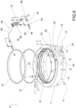
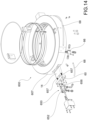
- the fixed lower tube 2' is provided, close to the upper end thereof, with a locking ring 6 suitable to engage the first movable tube 2 which, when the mast is in compact position as shown in Figures 1 and 1a , is accommodated in the fixed tube 2'.
- This locking ring 6 comprises an annular body 7, for example fastened to the outer side surface of the fixed lower tube 2' by means of a plurality of fastening grub screws 8.
- the locking ring 6 is internally provided with an annular sealing element 10 and one or more guide bands 12 suitable to promote the translation of the first movable tube 2 with respect to the lower fixed tube 2'.
- the locking ring 6 is provided with two radial locking latches 14 which are diametrically opposite to each other. Each latch 14 is slidingly inserted in a latch seat 16 thereof obtained in the annular body 7 of the locking ring 6. Each latch 14 is radially movable between an advanced locked position and a retracted, or inactive, released position of the first movable tube 2. When it is in advanced locked position, latch 14 radially protrudes from the inner wall of the locking ring 6 so as to engage a respective latch pocket obtained in the inner tube.
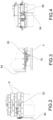
- Each latch 14 is operable in translation by means of a manual control lever 20 which is integral with an eccentric locking pin 22 which engages a pin slot 24 obtained in latch 14. Therefore, a radial translation of the latch 14 corresponds to the rotation of the locking pin 22 about a pin axis thereof, for example parallel to the mast axis V-V.
- the locking pin 22 is accommodated in a pin seat 26 obtained in the annular body 7 of the locking ring.
- the rotation of the locking pin 22 is controlled by a safety device 50 which comprises a single acting cylinder 52 at least partially accommodated in a respective cylinder seat 54 obtained in the annular body 7 of the locking ring 6 and communicating, for example with the pin seat 26.
- the single acting cylinder 52 is provided with a stem 56 which is movable between an advanced locked position and a retracted released position.
- Cylinder 52 is normally stressed by an elastic element, for example a spring, which keeps stem 56 in advanced locked position. In this advanced locked position, stem 56 engages a radial hole 58 of the locking pin 22, preventing the rotation from the locked position to the locked position of the latch 14.
- Cylinder 52 may be fed with pressurized air so as to bring stem 56 in retracted position such as to release the locking pin 22 and allow the rotation thereof towards the released position, and therefore the retraction of the latch 14.
- the single acting cylinder 52 is fed by the pressurized air in the pneumatic telescoping mast 1.
- Stem 56 may therefore be brought into retracted position only when the pressure of the air in mast 1 reaches a preset threshold value.
- the pneumatic circuit 60 has an air inlet connection 62 connected to mast 1 and from which a supply tube 64 extends which rises from the base of the mast towards the locking ring 6 and, for example by means of a distributor 66 which distributes the inlet air towards two end ducts 68, brings the pressurized air to the two single acting cylinders 52.
- the supply circuit 60 may be provided with control devices such as a pressure limiting device 70 and a manometer 72.
- Figures 9 and 9a show the locking ring 6 in a locked position of the inner tube 2, the pressure of the air in mast 1 being less than a preset value, for example of 1.3 bar.
- a preset value for example of 1.3 bar.
- FIGS 10, 10a show the locking ring 6 in a locked position of the inner tube 2, but with the stems 56 of the cylinders 52 in inactive retracted position, given that the pressure of the air in mast 1 is greater than the preset threshold value.
- Each control lever 20 is still in locked position, but it may be rotated into released position, in the direction of the arrows shown in Figure 10 .
- FIGS 11 and 11a show the locking ring 6 in released position of the inner tube 2.
- the control levers 20 have been rotated into released position.
- the latches 14 were then brought into retracted position. Since the stems 56 of the cylinders 52 are in retracted disengaged position from the respective locking pins 22, each control lever 20 may be rotated in both directions. Obviously, the lever may be brought back into locked position only when latch 14 is at the related pocket of the inner tube 2. Therefore, the inner tube can be raised or lowered in this circumstance.
- Figures 12 and 12a show the locking ring 6 in an intermediate configuration, typically following that of Figures 11, 11a , in which the pressure inside the mast is lower than the preset threshold value but the control levers 20 are in released position.
- the stems 56 are partially advanced under the force of the elastic element not countered by the pressure of the air; they engage the locking pin 22 but without preventing the rotation thereof.
- the latch pocket of the inner tube 2 is aligned with the respective latch 14, the latch may translate into advanced position and each stem 54 of cylinder 52 completely advances, thus locking the locking pin 22 in locked position.
- each movable tube 2 is provided with a locking ring 6 similar to that described above.
- the locking ring 6 of the fixed lower tube 2' is provided with the safety device 50 which controls the rotation of the control lever.
- a safety device could also be applied to one or more of the further locking rings associated with the movable tubes.
- Figure 13 shows the pneumatic diagram of the telescoping mast 1, where it can be noted how a compressed air source 80, e.g. a compressor, supplies in parallel the tubes of mast 1 and the single acting pneumatic cylinders 52.
- a compressed air source 80 e.g. a compressor
- Air is introduced into the mast itself, in order to extend the mast.
- An operator releases the locking means of the mast, for example starting from the locking ring of the upper tube up to reaching the lower ones associated with the locking ring of the fixed lower tube.
- the preset pressure e.g. 1.3 +/- 0.15 bar
- the single acting cylinder releases the locking pin, allowing the lever to bring the latch into retracted position to extend the inner tube.
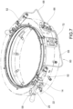
- Figures 14 to 18 show a variant of a locking ring 600.
- this locking ring 600 is similar to that of the above-described ring 6 but differs therefrom for the mode in which the safety device 650 is implemented.
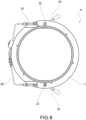
- the locking ring 600 is provided with two diametrically opposite radial latches 14 which are movable between an advanced locked position, in which they engage respective latch pockets obtained in the first movable tube, and a retracted released position, in which they are disengaged from such pockets, thus allowing the translation of the first movable tube 2.
- each latch 14 is directly moved by a single acting cylinder 652 feedable with a pressurized fluid.
- the single acting cylinder 652 has a stem 656 connected, for example by screwing, to the respective latch 14.
- the pressurized fluid may therefore be the same air supplied to the telescoping mast or, in an alternative embodiment, a fluid from another supply circuit of the pneumatic cylinder.
- the single acting pneumatic cylinder 652 controls the retraction of the latch 14, overcoming the force of an elastic element 657 when the pressure of the control fluid exceeds a preset threshold value.
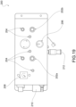
- the latch 14 and the pneumatic cylinder 652 are supported by a support plate 660 anchored to the annular body 607 of the locking ring 600.
- the two diametrically opposite pneumatic cylinders 652 are fed in parallel through a supply circuit 60 which comprises a distributor 66 which receives the pressurized air from the compressed air source and distributes the air flow to the two cylinders 652 by means of end tubes 68.
- the elastic element 657 may be a spring accommodated in the pneumatic cylinder or, as in the example shown in Figure 14 , it may consist of a pair of compression springs interposed between latch 14 and the support plate 660 and which tend to keep the latch in advanced locked position.
- the pneumatic cylinder 652 When the pneumatic cylinder 652 is supplied with a pressure of the control fluid which is equal to or greater than the preset threshold value, stem 656 is controlled to retract, overcoming the force of the elastic element and therefore moving latch 14 into the retracted released position.
- the telescoping mast 1 comprises an electric-pneumatic control box 100 which contains all the elements required to control the opening and closing of mast 1.
- control box 100 there is a first solenoid valve 112 for controlling the loading and bleeding of the compressed air into and from mast 1, and a second solenoid valve 114 for controlling the opening and closing of the actuators 52; 652 which implement the safety devices.
- the control box 100 further comprises a first pressure switch 118a suitable to check the presence of the network pressure, and a second pressure switch 118b suitable to detect the pressure in the chamber of the mast.
- Such a second pressure switch may alternatively also be installed directly at the base of the mast.
- the control box 100 may further contain a pneumatic circuit 120, for example comprising manually operable valves, capable of allowing the safe retraction of the mast if the electric control is out of use due to damage or due to a lack of power supply.
- a pneumatic circuit 120 for example comprising manually operable valves, capable of allowing the safe retraction of the mast if the electric control is out of use due to damage or due to a lack of power supply.
- the opening of mast 1 occurs by supplying pressurized air alone in the mast.
- the closing occurs by actuating the latches on the locking ring by means of a logic function.
- the logic function provides the consent of the opening of the latches, with the mast open, only if there is sufficient internal pressure to keep balanced the mast itself subject to the earth's gravitational action when the latches are retracted.
- the pneumatic telescoping mast 1 is also provided with a remote-control device 200 which acts as man-machine interface and which is operatively connected to the control box 100.
- the remote-control device 200 includes an electronic control board of the solenoid valves 112, 114 in the electric-pneumatic control box 100.
- the electronic board implements a logic defined by the inputs provided by the pressure switches 118a, 118b and by proximity sensors on the actuators of the locking ring and by a limit switch on the ring itself.
- the remote control device 200 is provided with buttons 202a, 202b for controlling the raising and lowering of the mast, light-signaling devices 204, a selector 206 for selecting the operating mode of the mast (automatic, manual, control OFF), a manometer 208 which indicates the pressure of the air in mast 1, a first electric connector 210 for communicating with the control box 100, and an optional second connector 212 which implements a protocol communication port 485.
- the pneumatic telescoping mast may remain open for an indefinite period of time.
- the mast may remain in such a configuration even in the absence of the whole control system.
- the operation of the telescoping mast in the lowering, i.e. closing, step provides the following actions.
- the operator turns the remote electric-pneumatic control 200 to automatic or manual mode and presses the lowering button 202b.
- the mast lowers.
- the button may be released in automatic mode.
- the button is to be kept pressed down in manual mode.
- the mast does not lower if the air in the mast is not sufficiently pressurized because the safety devices remain actuated. Under such a condition, one of the light-signaling devices 204 close to manometer 208 turns on red.
- the operator may press the raise button 202a so that the mast is filled with air until the minimum preset pressure is reached.
- a signaling device close to the raise button may flash to suggest the operator perform this action.
- the safety devices When the mast has reached the preset pressure - a condition that may be signaled by the lighting up of a signaling device - the safety devices are deactivated and, by pressing the lowering button 202b again, the mast begins bleeding air, thus allowing the lowering step.
- pressure transducers which check the pressure level of the air in the mast may be used and, for example they may allow or refuse the release of the locking means through suitable control logics.
- the transducers, logic ports and locking means may be made with pneumatic, electric, hydraulic, mechanical devices, or combinations of these technologies.
- the safety system described may further comprise a man-machine interface which shows the operator the state of the pressure in the mast so as to suggest the operations for the operator him/herself to carry out in order to.
- the locking means of the mast e.g. the latches, cannot be deactivated when the mast is extended.
Landscapes
- Engineering & Computer Science (AREA)
- Architecture (AREA)
- Civil Engineering (AREA)
- Structural Engineering (AREA)
- Actuator (AREA)
- Forklifts And Lifting Vehicles (AREA)
- Quick-Acting Or Multi-Walled Pipe Joints (AREA)
Claims (8)
- Pneumatischer Teleskopmast (1), zum Beispiel zum Tragen und Bewegen von militärischer Kommunikations-, Beleuchtungs- und/oder Überwachungsausrüstung, aufweisend eine Vielzahl teleskopisch-gekoppelter Dichtungsrohre (2, 2'), wobei die Rohre (2, 2') derart bedienbar sind, dass sie von einer eingefahrenen Konfiguration in eine ausgefahrene Konfiguration und umgekehrt wechseln können, wobei die Betätigung der Rohre (2, 2') durch Einleiten von Druckluft in den pneumatischen Teleskopmast (1) erfolgt, Rohrverriegelungseinrichtungen (3), die geeignet sind, die Rohre in der ausgefahrenen Konfiguration durch Eingriff oder Reibung zu verriegeln, selbst wenn in dem Mast keine Druckluft vorhanden ist, wobei die Rohrverriegelungseinrichtungen (3) zumindest eine Sicherheitsvorrichtung (50; 650) aufweisen, die derart konfiguriert ist, dass sie die Rohrverriegelungseinrichtungen (3) in der verriegelten Position hält und deaktivierbar ist, damit die Rohrverriegelungseinrichtungen (3) nur dann in die freigegebene Position wechseln können, wenn die Luft in dem Mast einen Solldruckwert erreicht, wobei der Mast dadurch gekennzeichnet ist, dass die Sicherheitsvorrichtung (50; 650) durch die Druckluft in dem Teleskopmast bedienbar ist.
- Teleskopmast nach dem vorstehenden Anspruch, wobei die Rohrverriegelungseinrichtungen (3) zumindest ein Rastelement (14) aufweisen, das zwischen einer inaktiven eingefahrenen Position und einer aktiven vorgeschobenen Position radial bewegbar ist, wobei das Rastelement (14) in eine Rastelementtasche eingreift, die in dem Rohr ausgebildet ist und einen geringfügig kleineren Durchmesser als jenen des Rohrs hat, welches das Rastelement trägt.
- Teleskopmast nach dem vorstehenden Anspruch, wobei die Bewegung des Rastelements (14) durch die Betätigung eines manuellen Steuerelements verursacht wird, das mit dem Rastelement wirkverbunden ist, und wobei die Sicherheitsvorrichtung (50; 650) einen einfachwirkenden Zylinder (52; 652) aufweist, der normalerweise durch zumindest ein elastisches Element vorgespannt wird, um die Betätigung des Steuerelements zu verhindern, und durch die Druckluft in dem Mast derart betätigbar ist, dass er von dem Steuerelement gelöst wird.
- Teleskopmast nach dem vorstehenden Anspruch, wobei das manuelle Steuerelement einen außermittigen Verriegelungsstift (22) aufweist, der mit einem Steuerhebel (20) integral ist und in einen Schlitz (24) des Rastelements (14) eingreift, wobei in dem außermittigen Verriegelungsstift (22) ein Verriegelungsloch (58) ausgebildet ist, in das ein Schaft (56) des einfachwirkenden Zylinders (52) eingreifen kann, um die Drehung des Verriegelungsstifts (22) zu sperren.
- Teleskopmast nach einem der Ansprüche 1 bis 2, wobei die Bewegung des Rastelements (14) durch einen einfachwirkenden Zylinder (52; 652) verursacht wird, der mit einem Druckfluid betreibbar ist, um das Rastelement (14) aus der aktiven vorgeschobenen Position in die inaktive zurückgezogene Position zu bringen.
- Teleskopmast nach dem vorstehenden Anspruch, wobei der einfachwirkende Zylinder (52; 652) durch die Druckluft in dem Mast betätigbar ist.
- Teleskopmast nach Anspruch 5, aufweisend einen Druckschalter (118b), der geeignet ist, den Druckwert der Luft in dem Mast zu detektieren, wobei der Zylinder durch eine Ansteuerschaltung betreibbar ist, die den Zylinder antreibt, wenn der Druckschalter das Erreichen des Solldruckwerts detektiert.
- Teleskopmast nach einem der vorstehenden Ansprüche, wobei die Vielzahl von Rohren (2, 2') des Masts ein feststehendes Basisrohr (2') aufweisen, wobei zumindest eine Sicherheitsvorrichtung (50; 650) von einem Sicherungsring (6; 600) getragen wird, der nahe an dem oberen Ende des feststehenden Basisrohrs (2') befestigt ist.
Applications Claiming Priority (1)
| Application Number | Priority Date | Filing Date | Title |
|---|---|---|---|
| PCT/IT2020/000052 WO2022003736A1 (en) | 2020-07-03 | 2020-07-03 | Pneumatic telescopic mast |
Publications (3)
| Publication Number | Publication Date |
|---|---|
| EP4176145A1 EP4176145A1 (de) | 2023-05-10 |
| EP4176145B1 true EP4176145B1 (de) | 2024-05-08 |
| EP4176145C0 EP4176145C0 (de) | 2024-05-08 |
Family
ID=72432979
Family Applications (1)
| Application Number | Title | Priority Date | Filing Date |
|---|---|---|---|
| EP20768721.1A Active EP4176145B1 (de) | 2020-07-03 | 2020-07-03 | Pneumatischer teleskopmast |
Country Status (9)
| Country | Link |
|---|---|
| US (1) | US12509902B2 (de) |
| EP (1) | EP4176145B1 (de) |
| CN (1) | CN116261617B (de) |
| AU (1) | AU2020456844A1 (de) |
| CA (1) | CA3188560A1 (de) |
| ES (1) | ES2982408T3 (de) |
| IL (1) | IL299551A (de) |
| TW (1) | TWI896648B (de) |
| WO (1) | WO2022003736A1 (de) |
Families Citing this family (1)
| Publication number | Priority date | Publication date | Assignee | Title |
|---|---|---|---|---|
| CN121112147A (zh) * | 2025-11-12 | 2025-12-12 | 温州市比萨列自动化机械有限公司 | 一种可自锁升降气杆 |
Family Cites Families (50)
| Publication number | Priority date | Publication date | Assignee | Title |
|---|---|---|---|---|
| US3738075A (en) * | 1971-06-16 | 1973-06-12 | Nat Crane Corp | Extendible boom with latch means for extension and retraction |
| FR2254122A1 (en) | 1973-12-05 | 1975-07-04 | Mors Materiel | Pneumatic telescopic mast - has pressure cylinder or clamping jaws controlling individual mast elements when extending or retracting |
| US4027802A (en) * | 1976-08-03 | 1977-06-07 | Reynolds Francis E | Building panel positioner |
| DE7629017U1 (de) * | 1976-09-17 | 1977-04-07 | Rupprecht, Walter, 6464 Linsengericht | Teleskopantennenmast |
| DE2744293C2 (de) * | 1977-10-01 | 1982-05-19 | Vereinigte Flugtechnische Werke Gmbh, 2800 Bremen | Höhenverstellbarer Geräteträger |
| US4594824A (en) * | 1982-03-29 | 1986-06-17 | Over-Lowe Company, Inc. | Telescoping tower for floodlighting equipment and the like |
| US4663900A (en) * | 1985-12-16 | 1987-05-12 | Singer Products Corporation | Locking mast and stop ring assembly |
| US4815757A (en) * | 1986-04-24 | 1989-03-28 | Hamilton Mark L | Rapid development surveillance vehicle and method |
| US4913458A (en) * | 1986-04-24 | 1990-04-03 | Hamilton Mark L | Surveillance vehicle control system |
| US4918896A (en) * | 1988-10-17 | 1990-04-24 | Harold Wiese | Telescopic flagpole |
| US5163650A (en) * | 1991-10-07 | 1992-11-17 | Tri-Ex Tower Corporation | Telescoping mast with improved holddown-locking mechanism |
| US5333422A (en) * | 1992-12-02 | 1994-08-02 | The United States Of America As Represented By The United States Department Of Energy | Lightweight extendable and retractable pole |
| US5572837A (en) * | 1994-08-05 | 1996-11-12 | The Will-Burt Company | Pneumatic telescoping mast |
| US5743635A (en) * | 1996-01-16 | 1998-04-28 | The Will-Burt Company | Pneumatically telescoping mast |
| US5718087A (en) * | 1996-05-02 | 1998-02-17 | The Will-Burt Company | Telescoping mast assembly |
| US5850713A (en) * | 1996-12-20 | 1998-12-22 | Yuasa Koki Co., Ltd | Device raising and lowering apparatus |
| US6046706A (en) * | 1997-06-20 | 2000-04-04 | Vargas; Robert A. | Antenna mast and method of using same |
| US6343568B1 (en) * | 1998-03-25 | 2002-02-05 | Mcclasky David R. | Non-rotating telescoping pole |
| US6299336B1 (en) * | 1999-08-26 | 2001-10-09 | The Will-Burt Company | Low profile lift mounting arrangement for telescoping mast |
| US7231741B2 (en) * | 2001-03-30 | 2007-06-19 | Sbc Technology Resources, Inc. | Mobile cellular telephone tower |
| US6767115B2 (en) * | 2001-11-16 | 2004-07-27 | The Will-Burt Company | Pneumatic telescoping mast |
| US7966777B2 (en) * | 2004-06-25 | 2011-06-28 | Itt Manufacturing Enterprises, Inc. | Mechanical lift, fully nesting, telescoping mast |
| US7497140B2 (en) * | 2005-03-11 | 2009-03-03 | The Will-Burt Company | Heavy Duty field mast |
| US7574832B1 (en) * | 2007-01-24 | 2009-08-18 | Lieberman Phillip L | Portable telescoping tower assembly |
| US9312596B2 (en) * | 2007-01-31 | 2016-04-12 | Jerry Newman | Mobile tower system |
| US7642987B2 (en) * | 2007-01-31 | 2010-01-05 | Jerry Newman | Monopole tower system |
| US7788858B1 (en) * | 2007-06-18 | 2010-09-07 | Ammons Douglas D | All terrain vehicle with telescoping camera |
| WO2009058241A2 (en) * | 2007-10-29 | 2009-05-07 | Us Tower Corporation | Polygon mast |
| CN101368451B (zh) * | 2008-09-16 | 2010-09-22 | 无锡市华鹰移动照明有限公司 | 气动升降桅杆抱闸装置 |
| US20110101716A1 (en) * | 2009-10-30 | 2011-05-05 | Matthew Nolte | Utility pole with removable supporting push button |
| CA2803886C (en) | 2010-06-25 | 2018-08-07 | Phillip M. Schmidt | Fluid-actuated telescoping tower for supporting heavy loads |
| US20120011804A1 (en) * | 2010-07-19 | 2012-01-19 | Michael Winterhalter | Composite poles |
| US8534004B2 (en) * | 2010-09-30 | 2013-09-17 | The Will-Burt Company | Rapid deployment and retraction telescoping mast system |
| US8922451B2 (en) * | 2011-01-25 | 2014-12-30 | The Will-Burt Company | Lockdown mechanism for an electric drive screw telescoping mast system |
| GB2491421B (en) * | 2011-08-09 | 2013-09-04 | Paul Michael Jones | Mobile light tower |
| US20140285005A1 (en) * | 2013-03-12 | 2014-09-25 | Eric P. Casteel | Solar Power Platform Capable of Charging During Transport |
| US20150023017A1 (en) * | 2013-07-18 | 2015-01-22 | Ride Inc. | Light tower |
| US9702162B2 (en) * | 2015-02-06 | 2017-07-11 | Trident Industries, LLC | Pultruded or extruded cross arm structures for utility poles |
| US9520642B2 (en) * | 2015-04-10 | 2016-12-13 | The Will-Burt Company | Pneumatic non-locking low-profile telescoping masts |
| US10113573B2 (en) * | 2015-11-05 | 2018-10-30 | Raytheon Company | Sequencing locking mechanism for telescoging structures |
| CN208010021U (zh) * | 2018-01-08 | 2018-10-26 | 常州朗卓机电科技有限公司 | 一种安全可靠的自锁气动升降桅杆 |
| US10483613B2 (en) * | 2018-02-02 | 2019-11-19 | Maverick Inc. | Telescopic antenna mast |
| US11117789B2 (en) * | 2018-06-04 | 2021-09-14 | Manitowoc Crane Companies, Llc | Telescoping boom with rotary extension and locking system |
| EP3802994B1 (de) * | 2018-06-05 | 2024-09-25 | The Will-Burt Company | Selbstverriegelnder teleskopmast |
| GB2582249B (en) * | 2019-01-25 | 2023-07-05 | South Midlands Communications Ltd | Telescopic mast |
| CN110486600B (zh) * | 2019-01-25 | 2020-11-24 | 深圳叠品科技有限公司 | 一种具有伸缩和收纳功能的折叠装置及其折叠风扇 |
| CN210289327U (zh) * | 2019-07-08 | 2020-04-10 | 常州朗卓机电科技有限公司 | 一种桅杆快拉式自锁 |
| IT202000004345A1 (it) * | 2020-03-02 | 2021-09-02 | Fireco S R L A Socio Unico | Assieme colonna telescopica pneumatica |
| DE112022002669A5 (de) * | 2021-05-19 | 2024-04-11 | Marcel Amann | Löschanordnung und verfahren zum löschen oder kühlen eines geparkten oder abgestellten fahrzeugs |
| US11952977B1 (en) * | 2023-11-29 | 2024-04-09 | Donald Gehring | Telescopic wind turbine tower |
-
2020
- 2020-07-03 US US18/012,925 patent/US12509902B2/en active Active
- 2020-07-03 EP EP20768721.1A patent/EP4176145B1/de active Active
- 2020-07-03 WO PCT/IT2020/000052 patent/WO2022003736A1/en not_active Ceased
- 2020-07-03 AU AU2020456844A patent/AU2020456844A1/en active Pending
- 2020-07-03 IL IL299551A patent/IL299551A/en unknown
- 2020-07-03 CN CN202080102714.7A patent/CN116261617B/zh active Active
- 2020-07-03 CA CA3188560A patent/CA3188560A1/en active Pending
- 2020-07-03 ES ES20768721T patent/ES2982408T3/es active Active
-
2021
- 2021-04-22 TW TW110114481A patent/TWI896648B/zh active
Also Published As
| Publication number | Publication date |
|---|---|
| EP4176145C0 (de) | 2024-05-08 |
| EP4176145A1 (de) | 2023-05-10 |
| ES2982408T3 (es) | 2024-10-16 |
| CA3188560A1 (en) | 2022-01-06 |
| IL299551A (en) | 2023-02-01 |
| CN116261617A (zh) | 2023-06-13 |
| US20230265673A1 (en) | 2023-08-24 |
| AU2020456844A1 (en) | 2023-02-09 |
| US12509902B2 (en) | 2025-12-30 |
| WO2022003736A1 (en) | 2022-01-06 |
| TWI896648B (zh) | 2025-09-11 |
| TW202202743A (zh) | 2022-01-16 |
| CN116261617B (zh) | 2025-07-11 |
Similar Documents
| Publication | Publication Date | Title |
|---|---|---|
| US6474922B2 (en) | Remote operation auxiliary hoist control and precision load positioner | |
| PL203380B1 (pl) | Układ hydrauliczny do obudowy ścian | |
| US8960807B2 (en) | Hydraulic circuit for longwall mining | |
| US10214873B2 (en) | Valve unit for a quick-changer and quick-change system | |
| US11629034B2 (en) | Crane telescope locking device | |
| EP4176145B1 (de) | Pneumatischer teleskopmast | |
| CN111216879B (zh) | 用于操作飞行器着陆装置的液压回路 | |
| US20170226600A1 (en) | Pressure relief valve for pressurized furnace | |
| US4565349A (en) | Fail safe hydraulic piloted pressure reducing and regulating valve | |
| HK40088151A (en) | Pneumatic telescopic mast | |
| HK40088151B (en) | Pneumatic telescopic mast | |
| MXPA01003109A (es) | Gato hidraulico impulsado por aire con control de aire de cierre automatico deteccion de carga. | |
| CN115535903B (zh) | 制动系统、安全制动的塔机起升机构及制动方法 | |
| US8876218B2 (en) | Hydraulic circuit for longwall support | |
| US8826799B2 (en) | Single effect hydraulic cylinder | |
| EP1895169A1 (de) | Druckenlastung und Kontrollventilanordnung | |
| US4153072A (en) | Pilot valve | |
| EP2428686B1 (de) | Vorrichtung zur kontrolle eines hydraulischen betätigungswerkzeuges und steuerun des steigens und des senkens einer last | |
| US3570371A (en) | Hydraulic actuator | |
| DK172502B1 (da) | En med endestillingsblokering forsynet trykluftcylinder, især til aktivering af røgaftræksklapper | |
| SU1664727A2 (ru) | Гидравлический привод выносных опор стрелового самоходного крана | |
| EP1881203A1 (de) | Hydraulisch betätigtes Ventil und Hydrauliksystem zur Betätigung einer Bremse | |
| JP2001525912A (ja) | 非常時対応の手動起動装置 | |
| EP0130062A1 (de) | Vorgesteuerte hydraulische Ausklinkvorrichtung für ein Ventil | |
| AU2013220787A1 (en) | Hydraulic circuit for longwall support |
Legal Events
| Date | Code | Title | Description |
|---|---|---|---|
| STAA | Information on the status of an ep patent application or granted ep patent |
Free format text: STATUS: UNKNOWN |
|
| STAA | Information on the status of an ep patent application or granted ep patent |
Free format text: STATUS: THE INTERNATIONAL PUBLICATION HAS BEEN MADE |
|
| PUAI | Public reference made under article 153(3) epc to a published international application that has entered the european phase |
Free format text: ORIGINAL CODE: 0009012 |
|
| STAA | Information on the status of an ep patent application or granted ep patent |
Free format text: STATUS: REQUEST FOR EXAMINATION WAS MADE |
|
| 17P | Request for examination filed |
Effective date: 20221223 |
|
| AK | Designated contracting states |
Kind code of ref document: A1 Designated state(s): AL AT BE BG CH CY CZ DE DK EE ES FI FR GB GR HR HU IE IS IT LI LT LU LV MC MK MT NL NO PL PT RO RS SE SI SK SM TR |
|
| REG | Reference to a national code |
Ref country code: HK Ref legal event code: DE Ref document number: 40088151 Country of ref document: HK |
|
| DAV | Request for validation of the european patent (deleted) | ||
| GRAP | Despatch of communication of intention to grant a patent |
Free format text: ORIGINAL CODE: EPIDOSNIGR1 |
|
| STAA | Information on the status of an ep patent application or granted ep patent |
Free format text: STATUS: GRANT OF PATENT IS INTENDED |
|
| INTG | Intention to grant announced |
Effective date: 20240126 |
|
| RIC1 | Information provided on ipc code assigned before grant |
Ipc: H01Q 1/10 20060101ALI20240112BHEP Ipc: H01Q 1/12 20060101ALI20240112BHEP Ipc: E04H 12/18 20060101AFI20240112BHEP |
|
| GRAS | Grant fee paid |
Free format text: ORIGINAL CODE: EPIDOSNIGR3 |
|
| GRAA | (expected) grant |
Free format text: ORIGINAL CODE: 0009210 |
|
| STAA | Information on the status of an ep patent application or granted ep patent |
Free format text: STATUS: THE PATENT HAS BEEN GRANTED |
|
| AK | Designated contracting states |
Kind code of ref document: B1 Designated state(s): AL AT BE BG CH CY CZ DE DK EE ES FI FR GB GR HR HU IE IS IT LI LT LU LV MC MK MT NL NO PL PT RO RS SE SI SK SM TR |
|
| REG | Reference to a national code |
Ref country code: GB Ref legal event code: FG4D |
|
| REG | Reference to a national code |
Ref country code: CH Ref legal event code: EP |
|
| REG | Reference to a national code |
Ref country code: DE Ref legal event code: R096 Ref document number: 602020030669 Country of ref document: DE |
|
| REG | Reference to a national code |
Ref country code: IE Ref legal event code: FG4D |
|
| U01 | Request for unitary effect filed |
Effective date: 20240604 |
|
| U07 | Unitary effect registered |
Designated state(s): AT BE BG DE DK EE FI FR IT LT LU LV MT NL PT SE SI Effective date: 20240613 |
|
| U20 | Renewal fee for the european patent with unitary effect paid |
Year of fee payment: 5 Effective date: 20240722 |
|
| PG25 | Lapsed in a contracting state [announced via postgrant information from national office to epo] |
Ref country code: IS Free format text: LAPSE BECAUSE OF FAILURE TO SUBMIT A TRANSLATION OF THE DESCRIPTION OR TO PAY THE FEE WITHIN THE PRESCRIBED TIME-LIMIT Effective date: 20240908 |
|
| PG25 | Lapsed in a contracting state [announced via postgrant information from national office to epo] |
Ref country code: HR Free format text: LAPSE BECAUSE OF FAILURE TO SUBMIT A TRANSLATION OF THE DESCRIPTION OR TO PAY THE FEE WITHIN THE PRESCRIBED TIME-LIMIT Effective date: 20240508 |
|
| PG25 | Lapsed in a contracting state [announced via postgrant information from national office to epo] |
Ref country code: GR Free format text: LAPSE BECAUSE OF FAILURE TO SUBMIT A TRANSLATION OF THE DESCRIPTION OR TO PAY THE FEE WITHIN THE PRESCRIBED TIME-LIMIT Effective date: 20240809 |
|
| REG | Reference to a national code |
Ref country code: ES Ref legal event code: FG2A Ref document number: 2982408 Country of ref document: ES Kind code of ref document: T3 Effective date: 20241016 |
|
| PG25 | Lapsed in a contracting state [announced via postgrant information from national office to epo] |
Ref country code: PL Free format text: LAPSE BECAUSE OF FAILURE TO SUBMIT A TRANSLATION OF THE DESCRIPTION OR TO PAY THE FEE WITHIN THE PRESCRIBED TIME-LIMIT Effective date: 20240508 |
|
| PG25 | Lapsed in a contracting state [announced via postgrant information from national office to epo] |
Ref country code: PL Free format text: LAPSE BECAUSE OF FAILURE TO SUBMIT A TRANSLATION OF THE DESCRIPTION OR TO PAY THE FEE WITHIN THE PRESCRIBED TIME-LIMIT Effective date: 20240508 Ref country code: NO Free format text: LAPSE BECAUSE OF FAILURE TO SUBMIT A TRANSLATION OF THE DESCRIPTION OR TO PAY THE FEE WITHIN THE PRESCRIBED TIME-LIMIT Effective date: 20240808 Ref country code: IS Free format text: LAPSE BECAUSE OF FAILURE TO SUBMIT A TRANSLATION OF THE DESCRIPTION OR TO PAY THE FEE WITHIN THE PRESCRIBED TIME-LIMIT Effective date: 20240908 Ref country code: HR Free format text: LAPSE BECAUSE OF FAILURE TO SUBMIT A TRANSLATION OF THE DESCRIPTION OR TO PAY THE FEE WITHIN THE PRESCRIBED TIME-LIMIT Effective date: 20240508 Ref country code: GR Free format text: LAPSE BECAUSE OF FAILURE TO SUBMIT A TRANSLATION OF THE DESCRIPTION OR TO PAY THE FEE WITHIN THE PRESCRIBED TIME-LIMIT Effective date: 20240809 Ref country code: RS Free format text: LAPSE BECAUSE OF FAILURE TO SUBMIT A TRANSLATION OF THE DESCRIPTION OR TO PAY THE FEE WITHIN THE PRESCRIBED TIME-LIMIT Effective date: 20240808 |
|
| PG25 | Lapsed in a contracting state [announced via postgrant information from national office to epo] |
Ref country code: CZ Free format text: LAPSE BECAUSE OF FAILURE TO SUBMIT A TRANSLATION OF THE DESCRIPTION OR TO PAY THE FEE WITHIN THE PRESCRIBED TIME-LIMIT Effective date: 20240508 |
|
| PG25 | Lapsed in a contracting state [announced via postgrant information from national office to epo] |
Ref country code: SK Free format text: LAPSE BECAUSE OF FAILURE TO SUBMIT A TRANSLATION OF THE DESCRIPTION OR TO PAY THE FEE WITHIN THE PRESCRIBED TIME-LIMIT Effective date: 20240508 Ref country code: RO Free format text: LAPSE BECAUSE OF FAILURE TO SUBMIT A TRANSLATION OF THE DESCRIPTION OR TO PAY THE FEE WITHIN THE PRESCRIBED TIME-LIMIT Effective date: 20240508 |
|
| PG25 | Lapsed in a contracting state [announced via postgrant information from national office to epo] |
Ref country code: SM Free format text: LAPSE BECAUSE OF FAILURE TO SUBMIT A TRANSLATION OF THE DESCRIPTION OR TO PAY THE FEE WITHIN THE PRESCRIBED TIME-LIMIT Effective date: 20240508 |
|
| PG25 | Lapsed in a contracting state [announced via postgrant information from national office to epo] |
Ref country code: SM Free format text: LAPSE BECAUSE OF FAILURE TO SUBMIT A TRANSLATION OF THE DESCRIPTION OR TO PAY THE FEE WITHIN THE PRESCRIBED TIME-LIMIT Effective date: 20240508 Ref country code: SK Free format text: LAPSE BECAUSE OF FAILURE TO SUBMIT A TRANSLATION OF THE DESCRIPTION OR TO PAY THE FEE WITHIN THE PRESCRIBED TIME-LIMIT Effective date: 20240508 Ref country code: RO Free format text: LAPSE BECAUSE OF FAILURE TO SUBMIT A TRANSLATION OF THE DESCRIPTION OR TO PAY THE FEE WITHIN THE PRESCRIBED TIME-LIMIT Effective date: 20240508 Ref country code: CZ Free format text: LAPSE BECAUSE OF FAILURE TO SUBMIT A TRANSLATION OF THE DESCRIPTION OR TO PAY THE FEE WITHIN THE PRESCRIBED TIME-LIMIT Effective date: 20240508 |
|
| PG25 | Lapsed in a contracting state [announced via postgrant information from national office to epo] |
Ref country code: MC Free format text: LAPSE BECAUSE OF FAILURE TO SUBMIT A TRANSLATION OF THE DESCRIPTION OR TO PAY THE FEE WITHIN THE PRESCRIBED TIME-LIMIT Effective date: 20240508 |
|
| REG | Reference to a national code |
Ref country code: DE Ref legal event code: R097 Ref document number: 602020030669 Country of ref document: DE |
|
| PLBE | No opposition filed within time limit |
Free format text: ORIGINAL CODE: 0009261 |
|
| STAA | Information on the status of an ep patent application or granted ep patent |
Free format text: STATUS: NO OPPOSITION FILED WITHIN TIME LIMIT |
|
| 26N | No opposition filed |
Effective date: 20250211 |
|
| U20 | Renewal fee for the european patent with unitary effect paid |
Year of fee payment: 6 Effective date: 20250523 |
|
| PG25 | Lapsed in a contracting state [announced via postgrant information from national office to epo] |
Ref country code: IE Free format text: LAPSE BECAUSE OF NON-PAYMENT OF DUE FEES Effective date: 20240703 |
|
| PGFP | Annual fee paid to national office [announced via postgrant information from national office to epo] |
Ref country code: ES Payment date: 20250801 Year of fee payment: 6 |
|
| PGFP | Annual fee paid to national office [announced via postgrant information from national office to epo] |
Ref country code: TR Payment date: 20250702 Year of fee payment: 6 |
|
| PGFP | Annual fee paid to national office [announced via postgrant information from national office to epo] |
Ref country code: GB Payment date: 20250724 Year of fee payment: 6 |
|
| PGFP | Annual fee paid to national office [announced via postgrant information from national office to epo] |
Ref country code: CH Payment date: 20250801 Year of fee payment: 6 |
|
| PG25 | Lapsed in a contracting state [announced via postgrant information from national office to epo] |
Ref country code: CY Free format text: LAPSE BECAUSE OF FAILURE TO SUBMIT A TRANSLATION OF THE DESCRIPTION OR TO PAY THE FEE WITHIN THE PRESCRIBED TIME-LIMIT; INVALID AB INITIO Effective date: 20200703 |
|
| PG25 | Lapsed in a contracting state [announced via postgrant information from national office to epo] |
Ref country code: HU Free format text: LAPSE BECAUSE OF FAILURE TO SUBMIT A TRANSLATION OF THE DESCRIPTION OR TO PAY THE FEE WITHIN THE PRESCRIBED TIME-LIMIT; INVALID AB INITIO Effective date: 20200703 |