EP4175758B1 - Sprühspender mit zwei behältern - Google Patents
Sprühspender mit zwei behältern Download PDFInfo
- Publication number
- EP4175758B1 EP4175758B1 EP21737217.6A EP21737217A EP4175758B1 EP 4175758 B1 EP4175758 B1 EP 4175758B1 EP 21737217 A EP21737217 A EP 21737217A EP 4175758 B1 EP4175758 B1 EP 4175758B1
- Authority
- EP
- European Patent Office
- Prior art keywords
- spray
- component
- reservoir
- components
- spray dispenser
- Prior art date
- Legal status (The legal status is an assumption and is not a legal conclusion. Google has not performed a legal analysis and makes no representation as to the accuracy of the status listed.)
- Active
Links
Images
Classifications
-
- A—HUMAN NECESSITIES
- A61—MEDICAL OR VETERINARY SCIENCE; HYGIENE
- A61K—PREPARATIONS FOR MEDICAL, DENTAL OR TOILETRY PURPOSES
- A61K8/00—Cosmetics or similar toiletry preparations
- A61K8/02—Cosmetics or similar toiletry preparations characterised by special physical form
- A61K8/04—Dispersions; Emulsions
- A61K8/046—Aerosols; Foams
-
- A—HUMAN NECESSITIES
- A61—MEDICAL OR VETERINARY SCIENCE; HYGIENE
- A61Q—SPECIFIC USE OF COSMETICS OR SIMILAR TOILETRY PREPARATIONS
- A61Q19/00—Preparations for care of the skin
-
- B—PERFORMING OPERATIONS; TRANSPORTING
- B05—SPRAYING OR ATOMISING IN GENERAL; APPLYING FLUENT MATERIALS TO SURFACES, IN GENERAL
- B05B—SPRAYING APPARATUS; ATOMISING APPARATUS; NOZZLES
- B05B11/00—Single-unit hand-held apparatus in which flow of contents is produced by the muscular force of the operator at the moment of use
- B05B11/01—Single-unit hand-held apparatus in which flow of contents is produced by the muscular force of the operator at the moment of use characterised by the means producing the flow
- B05B11/10—Pump arrangements for transferring the contents from the container to a pump chamber by a sucking effect and forcing the contents out through the dispensing nozzle
- B05B11/1081—Arrangements for pumping several liquids or other fluent materials from several containers, e.g. for mixing them at the moment of pumping
- B05B11/1084—Arrangements for pumping several liquids or other fluent materials from several containers, e.g. for mixing them at the moment of pumping each liquid or other fluent material being pumped by a separate pump
-
- B—PERFORMING OPERATIONS; TRANSPORTING
- B05—SPRAYING OR ATOMISING IN GENERAL; APPLYING FLUENT MATERIALS TO SURFACES, IN GENERAL
- B05B—SPRAYING APPARATUS; ATOMISING APPARATUS; NOZZLES
- B05B7/00—Spraying apparatus for discharge of liquids or other fluent materials from two or more sources, e.g. of liquid and air, of powder and gas
- B05B7/24—Spraying apparatus for discharge of liquids or other fluent materials from two or more sources, e.g. of liquid and air, of powder and gas with means, e.g. a container, for supplying liquid or other fluent material to a discharge device
-
- A—HUMAN NECESSITIES
- A61—MEDICAL OR VETERINARY SCIENCE; HYGIENE
- A61K—PREPARATIONS FOR MEDICAL, DENTAL OR TOILETRY PURPOSES
- A61K2800/00—Properties of cosmetic compositions or active ingredients thereof or formulation aids used therein and process related aspects
- A61K2800/10—General cosmetic use
-
- A—HUMAN NECESSITIES
- A61—MEDICAL OR VETERINARY SCIENCE; HYGIENE
- A61K—PREPARATIONS FOR MEDICAL, DENTAL OR TOILETRY PURPOSES
- A61K2800/00—Properties of cosmetic compositions or active ingredients thereof or formulation aids used therein and process related aspects
- A61K2800/80—Process related aspects concerning the preparation of the cosmetic composition or the storage or application thereof
- A61K2800/88—Two- or multipart kits
- A61K2800/882—Mixing prior to application
Definitions
- the present invention relates to dual reservoir spray dispenser, systems, kits and methods thereof.
- sprayable products e.g. liquid compositions are customarily packaged in a spray dispenser comprising a container for holding the product to be sprayed, a pump unit and an actuator assembly, including for example a push button and a nozzle tip, for dispensing the product in the form of a spray.
- a spray dispenser comprising a container for holding the product to be sprayed, a pump unit and an actuator assembly, including for example a push button and a nozzle tip, for dispensing the product in the form of a spray.
- Such spray dispensers are commercialized in numerous technical fields e.g. in skin care, hair care, personal care, grooming, oral care, health care, fabric care, home care, etc.
- the products to be sprayed are usually pre-formulated, ready-to-use products, and exhibit a good stability over time.
- the dispensers filled with the products may therefore be shelved and/or used during several months or even years.
- Dispensers comprising at least two reservoirs for storing separately two components to be mixed upon use and co-dispensed as a spray are known.
- dual reservoir spray dispensers comprising separate reservoirs and separate corresponding pump units, have been used for many years.
- both reservoirs are located side-by-side, instead of one-behind-the-other, such that, upon use, both containers are visible to the user when grasped in the user's hand.
- the spray direction is substantially perpendicular to the vertical plan passing by both reservoirs and the corresponding pump units.
- the actuator assembly may comprise two separate pipes with outlet orifices being located close to each other, such that the mixing of the components - so-called in-flight mixing - only occurs when being dispensed from the outlet orifices.
- the actuator may comprise two separate pipes respectively in fluid communication with the corresponding pump units, both pipes reaching a common pipe wherein both components are mixed before being dispensed.
- the path of the separate pipes and the common pipe may vary and may have for example a T-shape (the common path forming a straight angle with the separate pipes) or a Y-shape (the common path forming an obtuse angle e.g. from 120 to 150° with the separate pipes).
- Spray dispensers with side-by-side reservoirs of the above types are visually pleasing packaging being handy to grasp and to co-dispense the sprayable product.
- the user's experience is not completely satisfactory as the quality and the efficacy of the spraying may be altered over time such as for dispensers being used over a long period of time e.g. fragrance packaging, particularly packaging comprising fragrance-loaded microcapsules.
- fragrance packaging particularly packaging comprising fragrance-loaded microcapsules.
- the pipes may get partly or fully clogged and the dispenser should then be discarded before the reservoirs are emptied. Clogging may be due to various reasons including the drying of at least one of the components and/or the mixture, the decompositions of some compounds, the accumulation of residues, etc.
- Packaging used for dispensing fragrance compositions comprising microcapsules and a volatile solvent are particularly prone to getting clogged.
- the mixing of the components in the pipe may not be completely satisfactory.
- the actuator assembly usually comprises several parts, to be assembled together, which therefore increases the complexity, the size and the cost of the manufacturing process of the spray dispenser.
- US2017/0065993 discloses a dispenser for applying at least two compositions, the dispenser including at least two reservoirs for storing the at least two compositions separately, at least two pumps for pumping the at least two compositions, which pumps have different strokes, an exit orifice, and an actuator assembly.
- the difference between the first stroke and the second stroke is accommodated through flexure of a flexing member in the actuator assembly.
- the first composition includes microcapsules and the second composition includes a volatile solvent.
- the present invention relates to a spray dispensing system for mixing a first and a second components into a sprayable composition, the spray dispenser comprising:
- the spray dispensing system is a dispenser configured to separately hold two different components, while jointly dispensing them as a sprayable mixture (product).
- the spray dispensing system may be configured to be grasped in one user's hand, preferably for the reservoirs to be grasped in one user's hand while the actuator assembly being actuated by one finger of the same hand e.g. the index finger.
- the size of the dispensing system may then be such as to allow it to be handheld.
- the spray dispensing system according to the invention is advantageous in that the first and the second reservoirs are side-by-side; in that the spray actuator limits or even prevent the clogging from unmixed portions of the second component; and/or in that the spray actuator can be actuated by one finger for dispensing the given quantities of components.
- the spray dispensing system comprises a first reservoir, a second reservoir, a first pump unit, a second pump unit and an actuator assembly.
- the actuator assembly comprises a common spray actuator and a nozzle tip.
- the common spray actuator is operatively associated with the first and the second pump units.
- the spray actuator comprises a pipe.
- the pipe has been designed in order to allow dispensing given quantities of the first component and the second component and mixing them as a homogeneous sprayable mixture (composition), while preventing clogging over time by the first and/or the second components, particularly by the second component.
- the inventor has designed a common spray actuator comprising one single dispensing pipe having a specific path and comprising three different orifices provided in a specific sequence and with a specific spatial relationship.
- the pipe has a sinuous path and it comprises three different orifices i.e.
- the spray device according to the present invention is particularly suitable for holding a second component, or comprising compounds, being usually prone to clog dispensing pipes.
- the different elements of the spray dispensing system - i.e. at least the first and the second reservoirs, the first and the second corresponding units and the actuator assembly - may be assembled together along a longitudinal axis (or main axis).
- the other axis, when needed, are defined according to this longitudinal axis.
- the spray dispenser may usually rest on a flat surface e.g. a table by the bottom sides of the reservoirs (or the casing if present).
- the longitudinal axis substantially is the vertical axis and the spray dispenser comprises from bottom to top the reservoirs, the pump units and the actuator assembly.
- the first component and the second component are hold respectively in a first reservoir and a second reservoir.
- Each reservoir has an open end and may comprise a body and a neck. If necessary, for example if the body and the neck have differing cross-sections in size and/or in shape, the reservoir may also comprise a shoulder connecting the body to the neck.
- the body delimits the inner volume for holding the component.
- the body may comprise at least one circumferential wall and a bottom side.
- the bottom side is flat and allows the spray dispenser to rest on a flat surface.
- the neck comprises an open end.
- the component may be supplied to the reservoir via the open end.
- the neck is coupled to the corresponding pump unit in any suitable manner.
- the neck may be coupled to the corresponding pump unit by threading, bonding, welding or click fastening.
- a gasket particularly airtight gasket, may be disposed between the neck and the pump unit.
- the reservoirs may be fixedly coupled to the corresponding pump units. Hence, once the reservoirs are empty, the spray dispenser may be discarded. Alternatively, the reservoirs may be removably coupled to the corresponding pump units. Hence, once at least one of the reservoirs is empty, it may be refilled and coupled again to the pump unit or it may be replaced with a filled reservoir. Alternatively, one reservoir may be removably coupled to its corresponding pump unit, while the other reservoir may be fixedly coupled to its corresponding pump unit. Hence, only one reservoir may be changed, once emptied. Such embodiment may be useful for using a large non-replaceable reservoir with different replaceable reservoirs such as cartridges of smaller volumes.
- Each reservoir may have a volume from 1 to 250 mL, preferably from 2 to 100 mL, more preferably from 5 to 25 mL.
- the walls of each reservoir may be made of any suitable materials.
- the materials may be selected from the group consisting of ceramics, metal (for example aluminium), glass, resins, polymer-based materials (for example plastics) or composite material.
- Each reservoir may have any suitable shape or design.
- the reservoirs have shapes allowing them to be assembled side-by-side.
- the reservoirs may have complimentary shapes in order to be juxtaposed next to each other.
- Each reservoir may substantially have a tubular shape extending longitudinally from the bottom to the top i.e. from its bottom side to its neck.
- each reservoir may have a substantially non-tubular shape such as a conic shape widening longitudinally from the bottom to the top of the reservoir or vice versa.
- each reservoir may be any suitable cross-section such as circular, semi-circular, oval, semi-oval, square, rectangular, triangular, polygonal or star-shaped cross-sections.
- At least one reservoir may have rigid walls.
- the walls of the at least one reservoir are not elastically deformable, squeezable and/or shrinkable.
- both reservoirs have rigid walls.
- one of the two reservoirs or both reservoirs have non-rigid walls.
- At least one reservoir has transparent walls. In one embodiment, both reservoirs are transparent. In another embodiment, one reservoir is transparent, while the other reservoir is not transparent e.g. the other reservoir is translucid or opaque.
- the spray dispenser may comprise two separate, independent containers forming respectively a first reservoir and a second reservoir.
- both separate, independent containers are juxtaposed next to each other.
- one container may be placed within the other container.
- the spray dispensing system may only comprise one container comprising one separation wall thereby delimiting two different compartments forming respectively a first reservoir and a second reservoir.
- the spray dispenser may comprise a casing for holding in place both reservoirs.
- the casing may cover in part or in full the reservoirs.
- the casing may have an open bottom end and/or a side window, from which the reservoirs are introduced.
- At least one reservoir, and/or the casing if present, may comprise illustrations, instructions and/or any other type of information. Such illustrations, instructions and other type of information may be printed or engraved on the reservoir or stuck to it.
- the sprayable product (sprayable composition) is obtained by the mixture of the first component and the second component which are separately and respectively hold in the first and the second reservoirs.
- “Sprayable composition” means a composition comprising materials/ingredients suitable for topical application on mammalian keratinous tissue including skin and hair.
- substantially free of means an amount of an ingredient of 1 % or less, preferably 0.1 % or less, more preferably 0.01 % or less, most preferably of 0 %, by weight of the composition/component.
- Non-volatile refers to those materials which are liquid or solid under ambient conditions and have a measurable vapor pressure at 25 °C. These materials typically have a vapor pressure of less than about 0.0000001 mmHg, and an average boiling point typically greater than about 250 °C.
- Volatile refers to those materials that are liquid or solid under ambient conditions and which have a measurable vapor pressure at 25 °C. These materials typically have a vapor pressure of greater than about 0.0000001 mmHg, alternatively from about 0.02 mmHg to about 20 mmHg, and an average boiling point typically less than about 250 °C., alternatively less than about 235 °C.
- the first component and the second component have different formulations.
- the first component comprises a volatile solvent and the second component comprises microcapsules, particularly fragrance-loaded microcapsules.
- Both components may be in a liquid form at standard conditions.
- standard conditions is meant an ambient temperature from about 18 to about 25 °C, preferably about 20 °C and at atmospheric pressure.
- neither the first component nor the second component is in a powder form or a gaseous form at standard conditions.
- the components may differ at least by the presence of at least one material and/or by at least one material being present in different proportions and/or their physicochemical properties e.g. different viscosities and/or by their visual appearance e.g. different colors or different degree of clarity and/or turbidity, etc.
- the second component may be, or may comprise compounds being, prone to clogging dispensing pipes.
- the first component may prevent, or may comprise compounds preventing clogging of pipes.
- Each component may have a viscosity from 20 to 3000 mPa.s -1 , preferably from 50 to 600 mPa.s -1 , more preferably from 50 to 220 mPa.s -1 .
- the viscosity is measured using a Brookfield DV-II, spindle 3 at 60 rpm (measured at 25 °C).
- the components may be stored separately purely for aesthetical reasons such as providing components with different visual appearances.
- the components may be stored separately for chemical reasons.
- One of the components may comprise a material being inherently instable under specific conditions e.g. exposure to light and/or air. In such circumstances, this component may be hold in an opaque reservoir and/or an airtight reservoir.
- Both components may also comprise materials being incompatible when formulated together e.g. being immiscible such as water-soluble and water-insoluble materials.
- the aqueous component comprising water-soluble materials may be hold in one reservoir and the non-aqueous component e.g. an oily component comprising water-insoluble material may be hold in the other reservoir.
- One of the components may comprise one material being degraded by another material comprised in the other component.
- the components may comprise material chemically reacting together with mixed e.g. hair dyes in presence of oxidizing agents and alkalizing agents.
- the components are substantially free of a propellant and are not hold in pressurized reservoirs.
- the sprayable composition may be formed for a mixture of the first component and the second component in a volume ratio from 90:10 to 10:90, preferably from 80:20 to 20:80, more preferably from 70:30 to 30:70.
- the first and/or the second component may comprise a volatile solvent or a mixture of volatile solvents.
- the sprayable composition obtained upon mixing of the first and the second components, may comprise at least about 10%, alternatively at least about 30 %, alternatively at least about 40 %, alternatively at least about 50 %, alternatively at least about 60 %, alternatively at least about 70 %, alternatively at least about 80 %, alternatively at least about 90%, of a volatile solvent by weight of the sprayable composition.
- the component consists essentially of a volatile solvent.
- the volatile solvents may be relatively odourless and safe for use on human skin.
- the volatile solvents may be chosen from the group consisting of C 1 -C alcohols and mixtures thereof; preferably from the group consisting of ethanol, methanol, propanol, isopropanol, butanol, and mixtures thereof; more preferably ethanol.
- the first and/or the second component may comprise a non-volatile solvent or a mixture of non-volatile solvents.
- the sprayable composition obtained upon mixing of the first and the second components, may comprise at least about 10%, alternatively at least about 30 %, alternatively at least about 40 %, alternatively at least about 50 %, alternatively at least about 60 %, alternatively at least about 70 %, alternatively at least about 80 %, alternatively at least about 90%, of a non-volatile solvent by weight of the sprayable composition.
- the component consists essentially of a non-volatile solvent.
- the non-volatile solvents may be relatively odourless and safe for use on human skin.
- the volatile solvents may be chosen from the group consisting of benzyl benzoate, diethyl phthalate, isopropyl myristate, propylene glycol, dipropylene glycol, triethyl citrate, and mixtures thereof.
- the first and/or the second component may comprise a a fragrance.
- fragrance is used to indicate any odoriferous material(s).
- the term “fragrance” means a non-encapsulated fragrance, unless specifically stated otherwise. Any cosmetically acceptable fragrance may be suitable for use presently.
- the fragrance may be liquid or solid at room temperature.
- the fragrance may be a volatile or a non-volatile fragrance.
- the fragrance may be from synthetic origin or from natural origin, including from plant or animal origin. A wide variety of chemicals are known as fragrances.
- the fragrance may be chosen from the group consisting of alcohols, aldehydes, ketones, ethers, Schiff bases, nitriles, esters, alkenes and mixtures thereof.
- the fragrance may be pro-fragrances, such as a pro-fragrance chosen from the group consisting of acetal pro-fragrances, ketal pro-fragrances, ester pro-fragrances, hydrolysable inorganic-organic pro-fragrances, and mixtures thereof.
- the fragrances may be released from the pro-fragrance in a number of ways, such as for example by hydrolysis, by a shift in an equilibrium reaction, by a pH-change, by enzymatic release or any suitable.
- the fragrances may have a boiling point (BP) of about 500 °C or lower, alternatively of about 400 °C or lower, alternatively of about 350 °C or lower.
- BP boiling point
- the boiling points of many fragrances are disclosed in Perfume and Flavor Chemicals (Aroma Chemicals), Steffen Arctander (1969 ).
- the ClogP value of the individual fragrance materials may be about -0.5 or greater.
- ClogP means the logarithm to the base 10 of the octanol/water partition coefficient.
- the ClogP can be readily calculated from a program called "CLOGP” which is available from Daylight Chemical Information Systems Inc., Irvine Calif., USA or calculated using Advanced Chemistry Development (ACD/Labs) Software V11.02 ⁇ 1994-2014 ACD/Labs. Octanol/water partition coefficients are described in more detail in the U.S. patent 5,578,563 published on November 11th, 1996 .
- the sprayable composition obtained upon mixing of the first and the second components, may comprise from 0.001 to 40%, alternatively from 0.1 to 25%, alternatively from 0.25 to 20 %, alternatively from 0.5 to 15 %, of a non-encapsulated fragrance, by weight of the sprayable composition.
- the first or the second component may further comprise microcapsules. At least part of the fragrance is encapsulated in the microcapsules.
- the microcapsules may be any kind of microcapsule known in the art.
- the microcapsules may have a shell and a core material encapsulated by the shell.
- the core material of the microcapsules may include a fragrance, as defined herein.
- the shells of the microcapsules may be made from synthetic polymeric materials or naturally occurring polymers. Synthetic polymers may be derived from petroleum oil, for example.
- Synthetic polymers may be chosen from the group consisting of nylon, polyethylenes, polyamides, polystyrenes, polyisoprenes, polycarbonates, polyesters, polyureas, polyurethanes, polyolefins, polysaccharides, epoxy resins, vinyl polymers, polyacrylates, and mixtures thereof. Natural polymers occur in nature and may often be extracted from natural materials. Natural polymers may be chosen from the group consisting of silk, wool, gelatine, cellulose, proteins, and mixtures thereof.
- the sprayable composition, obtained upon mixing of the first and the second components may comprise from about 0.01 % to about 45% of microcapsules, by weight of the sprayable composition.
- the microcapsules may be friable microcapsules.
- a friable microcapsule is configured to release its core material when its shell is ruptured. The rupture may be caused by forces applied to the shell during mechanical interactions, for example during dispensing the component comprising them the pipe and the nozzle tip of the present spray dispenser.
- the microcapsules may have a shell with a volume weighted fracture strength of from about 0.1 to about 15.0 mega Pascals (MPas), alternatively from about 0.8 to about 15.0 MPa, alternatively from about 5.0 to about 12.0 MPa, alternatively from about 6.0 to about 10.0 MPa, when measured according to the Fracture Strength Test Method as described in U.S. patent application 2017/0065993 A1 , or any incremental value expressed in 0.1 MPa in this range, or any range formed by any of these values for fracture strength.
- MPas volume weighted fracture strength
- the microcapsules may have a median volume weighted particle size of from about 2 to about 80 ⁇ m, alternatively from about 10 to about 30 ⁇ m, alternatively from about 10 to about 20 ⁇ m, as determined by the Test Method for Determining Median Volume-Weighted Particle Size of Microcapsules as described in U.S. patent application 2017/0065993 A1 .
- the microcapsules may have various core material to shell weight ratios.
- the microcapsules may have a core material to shell ratio of about 70 to about 30 %, alternatively about 75 to about 25 %, alternatively about 80 to about 20 %, alternatively about 85 to about 15 %, alternatively about 90 to about 10 %, alternatively about 95 to about 5 %.
- the microcapsules may have shells made from any material in any size, shape, and configuration known in the art.
- the shells may include a polyacrylate material, preferably a polyacrylate random copolymer, more preferably a polyacrylate random copolymer having a total polyacrylate mass, including ingredients selected from the group including: an amine content of about 0.2 to about 2.0 % of the total polyacrylate mass, a carboxylic acid content of about 0.6 to about 6.0 % of the total polyacrylate mass, and a combination of an amine content of about 0.1 to about 1.0 % and a carboxylic acid content of about 0.3- to 3.0 % of total polyacrylate mass.
- the microcapsules may have various shell thicknesses.
- the microcapsule may have a shell with an overall thickness of about 1 to about 300 nm, alternatively from about 2 to about 200 nm.
- the microcapsules may also encapsulate one or more benefit agents.
- the benefit agents may be selected from the group consisting of cooling sensates, warming sensates, perfume oils, oils, pigments, dyes, chromogens, phase change materials, or any other suitable benefit agents known in the art.
- the microcapsules may also encapsulate a partitioning modifier. Suitable benefit agents and/or partitioning modifiers are disclosed in the U.S. patent application 2017/0065993 A1 .
- the shells of the microcapsules may comprise a reaction product of a first mixture in the presence of a second mixture comprising an emulsifier, the first mixture comprising a reaction product of i) an oil soluble or dispersible amine with ii) a multifunctional acrylate or methacrylate monomer or oligomer, an oil soluble acid and an initiator, the emulsifier comprising a water soluble or water dispersible acrylic acid alkyl acid copolymer, an alkali or alkali salt, and optionally a water phase initiator.
- Suitable amine monomers and emulsifiers are disclosed in the U.S. patent application 2017/0065993 A1 .
- microcapsules Processes for making the microcapsules are well known. Various processes for microencapsulation, and exemplary methods and materials, are set forth in U.S. patent 6,592,990 ; U.S. patent 2,730,456 ; U.S. patent 2,800,457 ; U.S. patent 2,800,458 ; U.S. patent 4,552,811 ; and U.S. patent application 2006/026351 8 A1 .
- the microcapsules may be spray-dried to form spray-dried microcapsules.
- the component may also comprise a carrier for the microcapsules.
- Suitable carriers may be chosen from the group consisting of water, silicone oils, other oils (for example mineral oil and/or isopropyl myristate) and fragrance oils; preferably water.
- the carrier should not significantly affect the performance of the microcapsules.
- Volatile solvents such as for example 95 % ethanol, are not suitable carriers for the microcapsules.
- the sprayable composition obtained upon mixing of the first and the second components, comprising the microcapsules may also comprise from about 0.1 to about 95 %, alternatively from about 5 to about 5 %, alternatively from about 5 to about 75 %, of a carrier, by weight of the sprayable composition.
- the mixture of the first and second components obtained i.e. the sprayable composition comprises from about 0.01 to about 75 %, alternatively from about 1 to about 60 %, alternatively from about 0.01 to about 60 %, alternatively from about 5 to about 50 %, of a carrier, preferably water, by weight of the sprayable composition.
- the sprayable composition obtained upon mixing of the first and the second components, may have a pH from about 2 to about 10, alternatively from about 3 to about 9, alternatively from about 4 to about 8.
- the first and/or the second component may also comprise a suspending agent, particularly a suspending agent for suspending the microcapsules and/or any other water-insoluble material dispersed in the component.
- the sprayable composition obtained upon mixing of the first and the second components, may comprise from about 0.01 to about 90%, alternatively from about 0.01 to 15 %, of suspending agents, by weight of the sprayable composition. Suitable suspending agents are disclosed in the U.S. patent application 2017/0065993 A1 rence.
- the first and/or the second component may also comprise an additional agent selected from the group consisting of a colouring agent, particularly a colouring agent in the form of a pigment, an antioxidant, a ultraviolet inhibitor, cyclodextrins, quenchers, skin care actives and their mixtures thereof.
- a colouring agent particularly a colouring agent in the form of a pigment, an antioxidant, a ultraviolet inhibitor, cyclodextrins, quenchers, skin care actives and their mixtures thereof.
- the sprayable composition obtained upon mixing of the first and the second components, comprises at least about 50%, alternatively at least about 75 %, alternatively at least about 90 %, of water, by weight of the component; from about 0.01 to about 90 %, alternatively from about 0.01 to about 15 %, alternatively from about 0.5 to about 15 %, of a suspending agent, by weight of the sprayable composition; wherein the component is free of propellants, volatile solvents (such as ethanol), detersive surfactants or mixtures thereof; wherein the microcapsules comprise a first fragrance and a shell that surrounds said first fragrance.
- the second component is substantially free of a wax, an antiperspirant, and mixtures thereof.
- the sprayable composition, obtained upon mixing of the first and the second components comprises about 20 % or less, alternatively about 10% or less, alternatively about 7% or less, of the microcapsules, by weight of the sprayable composition.
- the spray dispenser comprises two pump units being in fluid communication with the corresponding reservoirs.
- the pump units may be different from each other or may be the same. In a preferred embodiment, both pump units are the same.
- the pump units may be selected from any pump units suitable for dispensing a liquid product, which are customarily known.
- the pump unit may be a standard pump associated with a tube dipped into the component or, alternatively, the pump unit may be an airless pump associated with a piston. In a preferred embodiment, the pump unit is a standard pump associated with a tube dipped into the component.
- the spray dispenser comprises an actuator assembly including a common spray actuator and a nozzle tip.
- the common spray actuator is operatively associated with the first and the second pump units.
- the common spray actuator is associated to the pump unit in any suitable manner.
- the common spray actuator may be associated to the corresponding pump unit by bonding, welding or click fastening.
- a gasket particularly airtight gasket, may be disposed between the inlet orifices of the pipe and the corresponding pump units.
- the common spray actuator may be manually actuated by one finger only e.g. the index finger, while grasping the spray dispenser in one hand.
- Such type of spray actuators is conventionally called push buttons.
- the axial depression operation of the common spray actuator i.e. towards the top of the reservoirs simultaneous actuates both pump units.
- the common spray actuator is configured to dispense given quantities of the first component and the second component, when actuated.
- the quantities of components dispensed, and the ratio between the quantity of the first component and the quantity of the second component dispensed may vary depending the type of pump units used. For example, if both reservoirs have the same volume and both pump units are the same, the same quantity of the first component and the second component should be co-dispensed upon actuation of the common spray actuator, and the first reservoir and the second reservoir should be substantially emptied after the same number of actuations.
- the spray actuator comprises a pipe.
- the pipe has been designed in order to allow dispensing given quantities of the first component and the second component as a homogeneous sprayable mixture, while preventing clogging over time by the first and/or the second components, particularly by the second component.
- the spray dispensers according of the present invention, and particularly the arrangement of the common spray actuator and its pipe exhibit advantages in comparison to conventional dual reservoir spray dispensers, comprising two pump units, particularly those comprising a common spray actuator comprising a Y-shaped or a T-shaped piping system. Indeed, the actuation of conventional dual reservoir spray dispensers requires an increased force than a spray dispenser comprising only one pump unit, thereby rendering difficult actuating the spray actuator with one finger.
- conventional dual reservoir spray dispensers are prone to getting clogged, particularly if at least one of the two components tends to dry and/or to accumulate clogging residues when left in the pipe.
- conventional dual reservoir spray dispensers may have a reduced performance for mixing and spraying both components homogeneously.
- a common spray actuator characterized in that it allows providing a spray dispenser, wherein the first and the second reservoirs are side-by-side; in that it limits or even prevent the clogging from unmixed portions of the second component; and it that the spray actuator may be actuated by one finger for dispensing the given quantities of components.
- the inventor has designed a common spray actuator comprising one single dispensing and mixing pipe having a specific path and comprising three different orifices provided in a specific sequence and with a specific spatial relationship.
- the pipe comprises a first inlet orifice at one end, one outlet orifice at the other end, and a second inlet orifice located between the first inlet orifice and the outlet orifice.
- the first inlet orifice is in fluid communication with the first pump unit
- the second inlet orifice is in fluid communication with the second pump unit
- the outlet orifice is in fluid communication with the nozzle tip.
- a second section is formed between the second inlet orifice and the outlet orifice, in which both given quantities of the first and the second components are mixed before being dispensed through the nozzle tip as a homogeneous spray.
- the disposition of the second inlet orifice between the first inlet orifice and the outlet orifice is advantageous in that, after actuation, no unmixed portion of the second composition is left in the pipe, thereby limiting or even preventing its clogging. In such configuration, the first component flushes the second component.
- the inlet orifices and the outlet orifice are also spatially arranged so that the axis crossing both inlet orifices substantially perpendicularly intersect the axis of the spray direction passing through the outlet orifice and the nozzle tip.
- the pipe has a sinuous path running from the first inlet orifice via the second inlet orifice to the outlet orifice.
- This sinuous path - while allowing providing a dispensing device wherein no unmixed second component is left after use and while allowing the provision of side-by-side reservoirs - elongates the path of the portion of the first component and the mixture of the portions of both components, by comparison with Y-shaped and T-shaped piping systems.
- first inlet orifice and the second inlet orifice has a semi-circular shape and the section between the second inlet orifice and the outlet orifice has a "s" shape, so that the pipe has a lookalike "question-mark” shape ("?-shape").
- the pipe may have any suitable cross-sectional shape for example a circular or an elliptical cross-sectional shape.
- the surface of the cross-section and its size may vary or may be constant.
- the cross-sectional shape has no sharp corners, for avoiding the accumulation of compounds or residues, which may be prone to clogging the pipe.
- the pipe has a constant cross-section all along its length.
- the pipe may have a varying cross-section along its length.
- the cross-section of the first portion may be smaller (or bigger) than the cross-section of the second portion.
- the common spray actuator may comprise a body and a skirt circumferentially extending downwards (towards the reservoirs).
- the body and the skirt may be a unitary construction or may be different parts assembled together.
- the body may be a unitary construction or may be at least two parts assembled together.
- the provision of a unitary common spray actuator or alternatively of a multi-part common spray actuator may be dependent to the manufacturing method used.
- multi-part common spray actuators may be manufactured using conventional molding techniques, while unitary common spray actuators may be manufactured using additive manufacturing techniques, trivially known as 3D printing techniques.
- the pipe may be formed into the thickness of the body.
- the pipe may be a separate element, which is affixed to the body.
- a gap configured to receive the nozzle tip may be formed into the skirt. In an alternative embodiment, the gap may be formed into the thickness of the body.
- the spray actuator may comprise guiding means associated with corresponding means of the reservoirs and/or the pump units, for stabilizing the assembly of the spray actuator and for avoiding any unwanted rocking phenomenon.
- the spray actuator, and its constituting elements e.g. the body, the skirt and the pipe, may be made of any suitable materials.
- the materials may be selected from the group consisting of ceramics, glass, resins, polymer-based materials or composite materials.
- the spray actuator may dispense a volume of sprayable composition from 10 to 250 ⁇ L, preferably from 50 to 150 ⁇ L, more preferably from 70 to 100 ⁇ L.
- the spray dispenser also comprises a nozzle tip.
- the nozzle tip is in fluid communication with the dispensing pipe. Any conventional nozzle tip may be used.
- the nozzle tip may comprise a swirl chamber for atomizing the composition obtained by the mixing of the first and the second components.
- the nozzle tip is configured to spray the composition in a given direction.
- the direction of the spray is substantially perpendicular to the axis intersecting the inlet orifices of the pipe.
- the axis of the spray direction may be horizontal or may have a given angle for a horizontal axis of reference e.g. up to 30°.
- the spray pattern may vary depending on the nozzle tip used and may either be narrow, medium or large.
- the shape of the spray pattern depends the application targeted.
- the present invention relates to a spray dispenser comprising the spray dispensing system as described above, a first component and a second component;
- the present invention relates to a kit comprising, as described in the first aspect, a spray dispenser module comprising a first pump unit, a second pump unit, a nozzle tip and a common spray actuator; at least one first reservoir, optionally filled with a first component, configured to be removably coupled with the first pump unit; and at least one second reservoir, optionally filled with a second component, configured to be removably coupled with the second pump unit.
- the present invention relates to a method comprising the following steps:
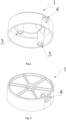
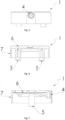
- FIG. 1 One embodiment of a common spray actuator 1 of the spray dispenser according to the present invention is shown in figures 1 to 6 , which should be construed as only being exemplary and not limitative.
- the common spray actuator as shown in figures 1 to 6 is configured to be operatively associated with a first and a second pump units (not shown), which are themselves respectively in fluid communication with a first and a second reservoirs (not shown).
- the common spray actuator comprises a pipe 2.
- the pipe 2 has been designed in order to allow dispensing given quantities of a first component and a second component and mixing them as a homogenous sprayable mixture, while preventing clogging over time by the first and/or the second components.
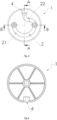
- the pipe 2 has a constant circular cross-section, forms a sinuous path and comprises three different orifices.
- the pipe 2 comprises a first inlet orifice 3 having a circular cross-section, located at one end of the pipe 2.
- the first inlet orifice 3 is in fluid communication with the first pump unit.
- the pipe 2 also comprises an outlet orifice 4 having a circular cross-section, located at the other end of the pipe 2.
- the outlet orifice 4 is in fluid communication with the nozzle tip (not shown).
- the pipe 2 comprises a second inlet orifice 5 having a circular cross-section, located between the first inlet orifice 3 and the outlet orifice 4.
- the second inlet orifice 5 is in fluid communication with the second pump unit.
- the axis crossing both inlet orifices 3, 4 (represented as B-B) substantially perpendicularly intersects the axis of the spray direction (represented as A-A) passing through the outlet orifice 4 and the nozzle tip.
- the pipe 2 particularly comprises two sections.
- the pipe 2 comprises a first section 21 formed between the first inlet orifice 3 and the second inlet orifice 5. A given quantity of the first component may be displaced from the first inlet orifice 3 towards the second inlet orifice 5, upon actuation.
- the pipe 2 also comprises a second section 22 formed between the second inlet orifice 5 and the outlet orifice 4. A given quantity of the first and the second components are mixed before being dispensed through the outlet orifice 4 (and the nozzle tip).
- the first section 21 between the first inlet orifice 3 and the second inlet orifice 5 has a "C" shape (semi-circular shape) and the second section 22 between the second inlet orifice 5 and the outlet orifice 4 has a "S" shape, so that the pipe 2 has a lookalike "question-mark” shape.
- the common spray comprises a body 7 and a skirt 8 circumferentially extending downwards.
- the body 7 and the skirt 8 forms a unitary construction.
- the pipe is formed into the thickness of the body.
Landscapes
- Health & Medical Sciences (AREA)
- Life Sciences & Earth Sciences (AREA)
- Veterinary Medicine (AREA)
- Animal Behavior & Ethology (AREA)
- General Health & Medical Sciences (AREA)
- Public Health (AREA)
- Chemical & Material Sciences (AREA)
- Dispersion Chemistry (AREA)
- Birds (AREA)
- Epidemiology (AREA)
- Dermatology (AREA)
- Containers And Packaging Bodies Having A Special Means To Remove Contents (AREA)
- Coating Apparatus (AREA)
- Cosmetics (AREA)
Claims (15)
- Spray-Abgabesystem zum Mischen einer ersten und einer zweiten Komponente zu einer sprühbaren Zusammensetzung, die Spray-Abgabevorrichtung umfassend:a) einen ersten Behälter, der so konfiguriert ist, dass er die erste Komponente und eine erste Pumpeneinheit, die in Fluidverbindung mit dem ersten Behälter steht, enthält;b) einen zweiten Behälter, der so konfiguriert ist, dass er die zweite Komponente, die sich von der ersten Komponente unterscheidet, und eine zweite Pumpeneinheit, die in Fluidverbindung mit dem zweiten Behälter steht, enthält;c) eine Düsenspitze, die so konfiguriert ist, dass sie die Zusammensetzung versprüht;d) einen gemeinsamen Sprühaktuator, der betriebsfähig mit der ersten und der zweiten Pumpeneinheit verbunden ist und ein Rohr (2) umfasst;wobei das Rohr (2) des gemeinsamen Sprühaktuators einen gewundenen Pfad aufweist und eine erste Einlassöffnung (3) an einem Ende, die in Fluidverbindung mit der ersten Pumpeneinheit steht; eine Auslassöffnung (4) an dem anderen Ende, die in Fluidverbindung mit der Düsenspitze steht; und eine zweite Einlassöffnung (5), die zwischen der ersten Einlassöffnung (3) und der Auslassöffnung (4) angeordnet ist und in Fluidverbindung mit der zweiten Pumpeneinheit steht, umfasst; undwobei die Achse, die beide Einlassöffnungen (3, 4) kreuzt, im Wesentlichen senkrecht die Achse der Sprührichtung schneidet, die durch die Auslassöffnung (4) und die Düsenspitze verläuft.
- Spray-Abgabesystem nach Anspruch 1, wobei jeder Behälter ein offenes Ende aufweist und einen Körper, einen Hals und optional eine Schulter umfasst, die den Körper mit dem Hals verbindet.
- Spray-Abgabesystem nach einem der vorhergehenden Ansprüche, wobei die Spray-Abgabevorrichtung zwei getrennte, unabhängige Behälter umfasst, die jeweils einen ersten Behälter und einen zweiten Behälter bilden; oder alternativ einen Behälter, der eine Trennwand umfasst, wodurch zwei unterschiedliche Kammern begrenzt werden, die jeweils einen ersten Behälter und einen zweiten Behälter bilden.
- Spray-Abgabesystem nach einem der vorhergehenden Ansprüche, wobei die Spray-Abgabevorrichtung ferner ein Gehäuse zum Halten beider Behälter umfasst.
- Spray-Abgabesystem nach einem der vorhergehenden Ansprüche, wobei das Rohr einen ersten Abschnitt (21) zwischen der ersten Einlassöffnung (3) und der zweiten Einlassöffnung (5) und einen zweiten Abschnitt (22) zwischen der zweiten Einlassöffnung (5) und der Auslassöffnung (4) umfasst; und wobei der erste Abschnitt (21) eine im Wesentlichen halbkreisförmige Form aufweist und der zweite Abschnitt (22) im Wesentlichen "S"-förmig ist.
- Spray-Abgabesystem nach einem der vorhergehenden Ansprüche, bei dem der gemeinsame Sprühaktuator einen Körper (7) und eine Schürze (8) umfasst, die sich in Umfangsrichtung nach unten erstreckt.
- Spray-Abgabevorrichtung, die das Abgabesystem nach einem der vorhergehenden Ansprüche umfasst, wobei das System ferner eine erste Komponente und eine zweite Komponente umfasst;wobei die erste Komponente in dem ersten Behälter und die zweite Komponente in dem zweiten Behälter enthalten ist;wobei sich die erste und die zweite Komponente voneinander unterscheiden; und wobei bei Betätigung des gemeinsamen Sprühaktuators die erste und die zweite Komponente homogen gemischt und als eine sprühbare Zusammensetzung abgegeben werden.
- Spray-Abgabevorrichtung nach Anspruch 7, wobei die Komponenten Hautpflegekomponenten, Haarpflegekomponenten, Körperpflegekomponenten, Pflegekomponenten, Mundpflegekomponenten, Gesundheitspflegekomponenten, Textilpflegekomponenten oder Haushaltspflegekomponenten sind.
- Spray-Abgabevorrichtung nach einem der Ansprüche 7 und 8, wobei die Komponenten bei Standardbedingungen in flüssiger Form vorliegen.
- Spray-Abgabevorrichtung nach einem der Ansprüche 7 bis 9, wobei sich die erste und die zweite Komponente voneinander mindestens durch das Vorliegen von mindestens einem Material, durch den Anteil von mindestens einem Material, durch mindestens eine physikalisch-chemische Eigenschaft, durch ihr optisches Erscheinungsbild und Kombinationen davon unterscheiden.
- Spray-Abgabevorrichtung nach einem der Ansprüche 7 bis 10, wobei eine der Komponenten ein Material, das unter bestimmten Bedingungen inhärent instabil ist, ein Material, das mit einem anderen Material, das in der anderen Komponente enthalten ist, inkompatibel ist, ein Material, das durch ein anderes Material, das in der anderen Komponente enthalten ist, abgebaut wird, eine Verbindung, die mit einem anderen Material, das in der anderen Komponente enthalten ist, chemisch reagiert, und Mischungen davon umfasst.
- Spray-Abgabevorrichtung nach einem der Ansprüche 7 bis 11, wobei die erste Komponente ein flüchtiges Lösungsmittel oder ein nicht-flüchtiges Lösungsmittel, vorzugsweise ein flüchtiges Lösungsmittel, besonders bevorzugt ein flüchtiges Mittel, bestehend aus C1-C-Alkoholen und Gemischen davon, noch bevorzugter ein flüchtiges Mittel, ausgewählt aus der Gruppe, bestehend aus Ethanol, Methanol, Propanol, Isopropanol, Butanol und Gemischen davon umfasst, wobei das flüchtige Mittel ganz besonders bevorzugt Ethanol ist.
- Spray-Abgabevorrichtung nach einem der Ansprüche 7 bis 12, wobei die zweite Komponente Duftstoffe, Mikrokapseln, einen geeigneten Trägerstoff und optional mindestens ein zusätzliches Mittel umfasst, das aus der Gruppe ausgewählt ist, die aus einem Suspendiermittel, einem Farbstoff, einem Antioxidans, einem UV-Inhibitor, Cyclodextrinen, Quenchern, Hautpflegewirkstoffen und Mischungen davon besteht; wobei mindestens ein Teil der Duftstoffe in den Mikrokapseln verkapselt ist.
- Kit, das ein Spray-Abgabesystem nach einem der Ansprüche 1 bis 6 umfasst, wobei der mindestens eine erste Behälter, der optional mit einer ersten Komponente gefüllt ist, so konfiguriert ist, dass er entfernbar mit der ersten Pumpeneinheit gekoppelt ist; und wobei der mindestens eine zweite Behälter, der optional mit einer zweiten Komponente gefüllt ist, so konfiguriert ist, dass er entfernbar mit der zweiten Pumpeneinheit gekoppelt ist.
- Verfahren, das die folgenden Schritte umfasst:a) Bereitstellen einer Spray-Abgabevorrichtung nach einem der Ansprüche 7 bis 13, die eine Spray-Abgabevorrichtung umfasst, die mit einer ersten und einer zweiten Komponente gefüllt ist;b) Betätigen des gemeinsamen Sprühaktuators zum Pumpen und dadurch homogenen Mischen bestimmter Anteile der ersten und der zweiten Komponente zum Erhalten einer sprühbaren Zusammensetzung; undc) Sprühen der sprühbaren Zusammensetzung.
Priority Applications (1)
| Application Number | Priority Date | Filing Date | Title |
|---|---|---|---|
| EP23215302.3A EP4311604B1 (de) | 2020-07-06 | 2021-05-20 | Sprühspender mit zwei behältern |
Applications Claiming Priority (2)
| Application Number | Priority Date | Filing Date | Title |
|---|---|---|---|
| US202063048283P | 2020-07-06 | 2020-07-06 | |
| PCT/US2021/033387 WO2022010578A1 (en) | 2020-07-06 | 2021-05-20 | Dual reservoir spray dispenser |
Related Child Applications (2)
| Application Number | Title | Priority Date | Filing Date |
|---|---|---|---|
| EP23215302.3A Division EP4311604B1 (de) | 2020-07-06 | 2021-05-20 | Sprühspender mit zwei behältern |
| EP23215302.3A Division-Into EP4311604B1 (de) | 2020-07-06 | 2021-05-20 | Sprühspender mit zwei behältern |
Publications (2)
| Publication Number | Publication Date |
|---|---|
| EP4175758A1 EP4175758A1 (de) | 2023-05-10 |
| EP4175758B1 true EP4175758B1 (de) | 2024-12-04 |
Family
ID=76744900
Family Applications (2)
| Application Number | Title | Priority Date | Filing Date |
|---|---|---|---|
| EP23215302.3A Active EP4311604B1 (de) | 2020-07-06 | 2021-05-20 | Sprühspender mit zwei behältern |
| EP21737217.6A Active EP4175758B1 (de) | 2020-07-06 | 2021-05-20 | Sprühspender mit zwei behältern |
Family Applications Before (1)
| Application Number | Title | Priority Date | Filing Date |
|---|---|---|---|
| EP23215302.3A Active EP4311604B1 (de) | 2020-07-06 | 2021-05-20 | Sprühspender mit zwei behältern |
Country Status (4)
| Country | Link |
|---|---|
| US (2) | US12383917B2 (de) |
| EP (2) | EP4311604B1 (de) |
| CN (1) | CN115942997A (de) |
| WO (1) | WO2022010578A1 (de) |
Cited By (1)
| Publication number | Priority date | Publication date | Assignee | Title |
|---|---|---|---|---|
| US12383917B2 (en) | 2020-07-06 | 2025-08-12 | Coty Inc. | Dual reservoir spray dispenser |
Families Citing this family (1)
| Publication number | Priority date | Publication date | Assignee | Title |
|---|---|---|---|---|
| CN116723847A (zh) * | 2020-09-16 | 2023-09-08 | 萨诺蒂泽研究开发公司 | 双腔室喷雾装置 |
Family Cites Families (40)
| Publication number | Priority date | Publication date | Assignee | Title |
|---|---|---|---|---|
| US2730456A (en) | 1953-06-30 | 1956-01-10 | Ncr Co | Manifold record material |
| NL95043C (de) | 1953-06-30 | |||
| US2800457A (en) | 1953-06-30 | 1957-07-23 | Ncr Co | Oil-containing microscopic capsules and method of making them |
| US4552811A (en) | 1983-07-26 | 1985-11-12 | Appleton Papers Inc. | Capsule manufacture |
| FR2598392B1 (fr) * | 1986-05-09 | 1988-08-26 | Oreal | Conditionnement pour deux recipients pressurises |
| FR2603558B1 (fr) * | 1986-09-04 | 1988-11-18 | Oreal | Tete de distribution d'un produit pateux resultant du melange de deux composants stockes separement et ensemble de conditionnement dote d'une telle tete de distribution |
| US5152461A (en) * | 1990-10-01 | 1992-10-06 | Proctor Rudy R | Hand operated sprayer with multiple fluid containers |
| US5470416A (en) * | 1992-04-16 | 1995-11-28 | The Budd Company | Bonding method using mixture of adhesive and non-compressible beads |
| US5402916A (en) * | 1993-06-22 | 1995-04-04 | Nottingham Spirk Design Associates | Dual chamber sprayer with metering assembly |
| US5398846A (en) * | 1993-08-20 | 1995-03-21 | S. C. Johnson & Son, Inc. | Assembly for simultaneous dispensing of multiple fluids |
| FR2722431B1 (fr) * | 1994-07-12 | 1996-09-13 | Lir France Sa | Distributeur double pour produits fluides |
| US5578563A (en) | 1994-08-12 | 1996-11-26 | The Procter & Gamble Company | Composition for reducing malodor impression on inanimate surfaces |
| FR2789371B1 (fr) * | 1999-02-05 | 2001-04-27 | Sofab | Distributeur de produits chimiquement instables |
| US6308863B1 (en) * | 1999-09-02 | 2001-10-30 | Owens-Brockway Plastic Products Inc. | Dual chamber package for pressurized products |
| AU8852601A (en) | 2000-09-06 | 2002-03-22 | Appleton Paper Inc | In situ microencapsulated adhesive |
| US6454135B1 (en) * | 2001-09-18 | 2002-09-24 | Owens-Illinois Closure Inc. | Dual liquid dispensing packages |
| US7906473B2 (en) * | 2002-09-13 | 2011-03-15 | Bissell Homecare, Inc. | Manual spray cleaner |
| DE10333924B3 (de) * | 2003-07-25 | 2004-10-07 | Wella Ag | Mehrkomponentenverpackung, Mischverfahren und Verwendung von statischen Mikromischern |
| US7490743B2 (en) * | 2004-10-22 | 2009-02-17 | Kenneth J Herzog | Dispenser assembly |
| GB0426429D0 (en) * | 2004-12-01 | 2005-01-05 | Incro Ltd | Nozzle arrangement and dispenser incorporating nozzle arrangement |
| FR2885495B1 (fr) * | 2005-05-10 | 2007-08-10 | Oreal | Ensemble de conditionnement et de distribution d'un produit |
| WO2006127453A2 (en) | 2005-05-23 | 2006-11-30 | Appleton Papers Inc. | Water-in-oil capsule manufacture process and microcapsules produced by such process |
| AT503046B1 (de) * | 2005-12-15 | 2009-05-15 | Josef Mikl | Sprühpistole |
| GB2484262B (en) * | 2010-09-29 | 2013-08-21 | Tristel Plc | Hand sanitizer |
| US8474659B2 (en) * | 2011-03-23 | 2013-07-02 | The Clorox Company | Multi-chamber fluid dispensing container with dip tubes |
| EP2570190A1 (de) * | 2011-09-15 | 2013-03-20 | Braun GmbH | Sprühdüse zum Abgeben einer Flüssigkeit und Sprüheinrichtung, die eine solche Sprühdüse umfasst |
| US8544495B1 (en) * | 2012-10-31 | 2013-10-01 | Ronald C. Weingart | Dispenser for liquid and/or solid chemicals |
| KR101426790B1 (ko) * | 2013-07-26 | 2014-08-05 | (주)민진 | 화장품 용기 |
| US9610598B2 (en) * | 2014-04-18 | 2017-04-04 | The Clorox Company | Trigger-dispensing device for two or more liquids |
| US9931657B2 (en) * | 2014-04-18 | 2018-04-03 | The Clorox Company | Dual chamber spray dispenser with a single delivery tube |
| EP3151972B1 (de) * | 2014-06-09 | 2018-07-25 | The Procter and Gamble Company | Spülspender zur bereitstellung einer konsistenten benutzererfahrung |
| CN106413909A (zh) * | 2014-06-09 | 2017-02-15 | 宝洁公司 | 用于递送一致的消费者体验的分配器 |
| US9839931B2 (en) * | 2015-09-09 | 2017-12-12 | The Procter & Gamble Company | Dispensers for dispensing microcapsules |
| US9579676B1 (en) * | 2015-09-09 | 2017-02-28 | The Procter & Gamble Company | Dispensers for microcapsules |
| US9757754B2 (en) | 2015-09-09 | 2017-09-12 | The Procter & Gamble Company | Dispensers for dispensing microcapsules |
| CN107921453A (zh) * | 2015-09-09 | 2018-04-17 | 宝洁公司 | 用于分配微胶囊的分配器 |
| WO2017091421A1 (en) * | 2015-11-27 | 2017-06-01 | The Procter & Gamble Company | Multi-component fragrance dispensing apparatus |
| JP6582027B2 (ja) * | 2016-09-29 | 2019-09-25 | 花王株式会社 | 泡吐出容器 |
| CN110307139B (zh) * | 2019-07-19 | 2024-01-30 | 深圳市通产丽星科技集团有限公司 | 双泵出液容器 |
| CN115942997A (zh) | 2020-07-06 | 2023-04-07 | 科蒂公司 | 双储存器喷雾分配器 |
-
2021
- 2021-05-20 CN CN202180044124.8A patent/CN115942997A/zh active Pending
- 2021-05-20 EP EP23215302.3A patent/EP4311604B1/de active Active
- 2021-05-20 US US18/001,027 patent/US12383917B2/en active Active
- 2021-05-20 WO PCT/US2021/033387 patent/WO2022010578A1/en not_active Ceased
- 2021-05-20 EP EP21737217.6A patent/EP4175758B1/de active Active
-
2025
- 2025-07-17 US US19/272,357 patent/US20250339868A1/en active Pending
Cited By (1)
| Publication number | Priority date | Publication date | Assignee | Title |
|---|---|---|---|---|
| US12383917B2 (en) | 2020-07-06 | 2025-08-12 | Coty Inc. | Dual reservoir spray dispenser |
Also Published As
| Publication number | Publication date |
|---|---|
| US20230149961A1 (en) | 2023-05-18 |
| WO2022010578A1 (en) | 2022-01-13 |
| US20250339868A1 (en) | 2025-11-06 |
| US12383917B2 (en) | 2025-08-12 |
| EP4175758A1 (de) | 2023-05-10 |
| EP4311604A2 (de) | 2024-01-31 |
| EP4311604B1 (de) | 2024-12-04 |
| CN115942997A (zh) | 2023-04-07 |
| EP4311604C0 (de) | 2024-12-04 |
| EP4311604A3 (de) | 2024-04-03 |
Similar Documents
| Publication | Publication Date | Title |
|---|---|---|
| US20250339868A1 (en) | Dual reservoir spray dispenser | |
| US10029267B2 (en) | Multi-component fragrance dispensing apparatus | |
| KR100797267B1 (ko) | 유동성 혼합물을 혼합하고 분배하기 위한 디스펜서 | |
| AU2015269207B2 (en) | A fluid dispensing system and methods relating thereto | |
| JP2968944B2 (ja) | エアゾール容器用バルブ装置 | |
| AU733435B2 (en) | Dual compartment package and pumps | |
| CA2267174C (en) | Dual compartment package | |
| US6045813A (en) | Lotions and gels with active ingredients in beads | |
| AU2003300549B2 (en) | Method of creating a cosmetic spray | |
| US20060000852A1 (en) | Portable dispenser for mixing and dispensing fluid mixtures | |
| US20130254136A1 (en) | Customizable dispensing systems and dispensing systems delivering a dose of fragrance upon actuation | |
| KR20190018702A (ko) | 개인 관리용 도포기 | |
| JP7441956B2 (ja) | 小出し器具ならびにその製造方法および使用方法 | |
| US20170151364A1 (en) | Multi-component fragrance dispensing apparatus | |
| US20170151363A1 (en) | Portable multi-fragrance compositional dispensing system and methods of use | |
| JPH01153476A (ja) | ペースト状製品用ディスペンサ | |
| US11745199B2 (en) | Dispensing device |
Legal Events
| Date | Code | Title | Description |
|---|---|---|---|
| STAA | Information on the status of an ep patent application or granted ep patent |
Free format text: STATUS: UNKNOWN |
|
| STAA | Information on the status of an ep patent application or granted ep patent |
Free format text: STATUS: THE INTERNATIONAL PUBLICATION HAS BEEN MADE |
|
| PUAI | Public reference made under article 153(3) epc to a published international application that has entered the european phase |
Free format text: ORIGINAL CODE: 0009012 |
|
| STAA | Information on the status of an ep patent application or granted ep patent |
Free format text: STATUS: REQUEST FOR EXAMINATION WAS MADE |
|
| 17P | Request for examination filed |
Effective date: 20230111 |
|
| AK | Designated contracting states |
Kind code of ref document: A1 Designated state(s): AL AT BE BG CH CY CZ DE DK EE ES FI FR GB GR HR HU IE IS IT LI LT LU LV MC MK MT NL NO PL PT RO RS SE SI SK SM TR |
|
| DAV | Request for validation of the european patent (deleted) | ||
| DAX | Request for extension of the european patent (deleted) | ||
| STAA | Information on the status of an ep patent application or granted ep patent |
Free format text: STATUS: EXAMINATION IS IN PROGRESS |
|
| 17Q | First examination report despatched |
Effective date: 20231025 |
|
| GRAP | Despatch of communication of intention to grant a patent |
Free format text: ORIGINAL CODE: EPIDOSNIGR1 |
|
| STAA | Information on the status of an ep patent application or granted ep patent |
Free format text: STATUS: GRANT OF PATENT IS INTENDED |
|
| INTG | Intention to grant announced |
Effective date: 20240703 |
|
| GRAS | Grant fee paid |
Free format text: ORIGINAL CODE: EPIDOSNIGR3 |
|
| GRAA | (expected) grant |
Free format text: ORIGINAL CODE: 0009210 |
|
| STAA | Information on the status of an ep patent application or granted ep patent |
Free format text: STATUS: THE PATENT HAS BEEN GRANTED |
|
| AK | Designated contracting states |
Kind code of ref document: B1 Designated state(s): AL AT BE BG CH CY CZ DE DK EE ES FI FR GB GR HR HU IE IS IT LI LT LU LV MC MK MT NL NO PL PT RO RS SE SI SK SM TR |
|
| REG | Reference to a national code |
Ref country code: CH Ref legal event code: EP |
|
| REG | Reference to a national code |
Ref country code: DE Ref legal event code: R096 Ref document number: 602021022885 Country of ref document: DE |
|
| P01 | Opt-out of the competence of the unified patent court (upc) registered |
Free format text: CASE NUMBER: APP_61914/2024 Effective date: 20241119 |
|
| REG | Reference to a national code |
Ref country code: IE Ref legal event code: FG4D |
|
| REG | Reference to a national code |
Ref country code: LT Ref legal event code: MG9D |
|
| REG | Reference to a national code |
Ref country code: NL Ref legal event code: MP Effective date: 20241204 |
|
| PG25 | Lapsed in a contracting state [announced via postgrant information from national office to epo] |
Ref country code: HR Free format text: LAPSE BECAUSE OF FAILURE TO SUBMIT A TRANSLATION OF THE DESCRIPTION OR TO PAY THE FEE WITHIN THE PRESCRIBED TIME-LIMIT Effective date: 20241204 |
|
| PG25 | Lapsed in a contracting state [announced via postgrant information from national office to epo] |
Ref country code: FI Free format text: LAPSE BECAUSE OF FAILURE TO SUBMIT A TRANSLATION OF THE DESCRIPTION OR TO PAY THE FEE WITHIN THE PRESCRIBED TIME-LIMIT Effective date: 20241204 |
|
| PG25 | Lapsed in a contracting state [announced via postgrant information from national office to epo] |
Ref country code: BG Free format text: LAPSE BECAUSE OF FAILURE TO SUBMIT A TRANSLATION OF THE DESCRIPTION OR TO PAY THE FEE WITHIN THE PRESCRIBED TIME-LIMIT Effective date: 20241204 |
|
| PG25 | Lapsed in a contracting state [announced via postgrant information from national office to epo] |
Ref country code: ES Free format text: LAPSE BECAUSE OF FAILURE TO SUBMIT A TRANSLATION OF THE DESCRIPTION OR TO PAY THE FEE WITHIN THE PRESCRIBED TIME-LIMIT Effective date: 20241204 |
|
| PG25 | Lapsed in a contracting state [announced via postgrant information from national office to epo] |
Ref country code: NO Free format text: LAPSE BECAUSE OF FAILURE TO SUBMIT A TRANSLATION OF THE DESCRIPTION OR TO PAY THE FEE WITHIN THE PRESCRIBED TIME-LIMIT Effective date: 20250304 |
|
| PG25 | Lapsed in a contracting state [announced via postgrant information from national office to epo] |
Ref country code: LV Free format text: LAPSE BECAUSE OF FAILURE TO SUBMIT A TRANSLATION OF THE DESCRIPTION OR TO PAY THE FEE WITHIN THE PRESCRIBED TIME-LIMIT Effective date: 20241204 Ref country code: GR Free format text: LAPSE BECAUSE OF FAILURE TO SUBMIT A TRANSLATION OF THE DESCRIPTION OR TO PAY THE FEE WITHIN THE PRESCRIBED TIME-LIMIT Effective date: 20250305 |
|
| PG25 | Lapsed in a contracting state [announced via postgrant information from national office to epo] |
Ref country code: RS Free format text: LAPSE BECAUSE OF FAILURE TO SUBMIT A TRANSLATION OF THE DESCRIPTION OR TO PAY THE FEE WITHIN THE PRESCRIBED TIME-LIMIT Effective date: 20250304 |
|
| PG25 | Lapsed in a contracting state [announced via postgrant information from national office to epo] |
Ref country code: NL Free format text: LAPSE BECAUSE OF FAILURE TO SUBMIT A TRANSLATION OF THE DESCRIPTION OR TO PAY THE FEE WITHIN THE PRESCRIBED TIME-LIMIT Effective date: 20241204 |
|
| REG | Reference to a national code |
Ref country code: AT Ref legal event code: MK05 Ref document number: 1747603 Country of ref document: AT Kind code of ref document: T Effective date: 20241204 |
|
| PG25 | Lapsed in a contracting state [announced via postgrant information from national office to epo] |
Ref country code: SM Free format text: LAPSE BECAUSE OF FAILURE TO SUBMIT A TRANSLATION OF THE DESCRIPTION OR TO PAY THE FEE WITHIN THE PRESCRIBED TIME-LIMIT Effective date: 20241204 |
|
| PG25 | Lapsed in a contracting state [announced via postgrant information from national office to epo] |
Ref country code: PL Free format text: LAPSE BECAUSE OF FAILURE TO SUBMIT A TRANSLATION OF THE DESCRIPTION OR TO PAY THE FEE WITHIN THE PRESCRIBED TIME-LIMIT Effective date: 20241204 |
|
| PG25 | Lapsed in a contracting state [announced via postgrant information from national office to epo] |
Ref country code: IS Free format text: LAPSE BECAUSE OF FAILURE TO SUBMIT A TRANSLATION OF THE DESCRIPTION OR TO PAY THE FEE WITHIN THE PRESCRIBED TIME-LIMIT Effective date: 20250404 |
|
| PG25 | Lapsed in a contracting state [announced via postgrant information from national office to epo] |
Ref country code: PT Free format text: LAPSE BECAUSE OF FAILURE TO SUBMIT A TRANSLATION OF THE DESCRIPTION OR TO PAY THE FEE WITHIN THE PRESCRIBED TIME-LIMIT Effective date: 20250404 |
|
| PG25 | Lapsed in a contracting state [announced via postgrant information from national office to epo] |
Ref country code: EE Free format text: LAPSE BECAUSE OF FAILURE TO SUBMIT A TRANSLATION OF THE DESCRIPTION OR TO PAY THE FEE WITHIN THE PRESCRIBED TIME-LIMIT Effective date: 20241204 |
|
| PG25 | Lapsed in a contracting state [announced via postgrant information from national office to epo] |
Ref country code: RO Free format text: LAPSE BECAUSE OF FAILURE TO SUBMIT A TRANSLATION OF THE DESCRIPTION OR TO PAY THE FEE WITHIN THE PRESCRIBED TIME-LIMIT Effective date: 20241204 Ref country code: AT Free format text: LAPSE BECAUSE OF FAILURE TO SUBMIT A TRANSLATION OF THE DESCRIPTION OR TO PAY THE FEE WITHIN THE PRESCRIBED TIME-LIMIT Effective date: 20241204 |
|
| PG25 | Lapsed in a contracting state [announced via postgrant information from national office to epo] |
Ref country code: SK Free format text: LAPSE BECAUSE OF FAILURE TO SUBMIT A TRANSLATION OF THE DESCRIPTION OR TO PAY THE FEE WITHIN THE PRESCRIBED TIME-LIMIT Effective date: 20241204 |
|
| PG25 | Lapsed in a contracting state [announced via postgrant information from national office to epo] |
Ref country code: CZ Free format text: LAPSE BECAUSE OF FAILURE TO SUBMIT A TRANSLATION OF THE DESCRIPTION OR TO PAY THE FEE WITHIN THE PRESCRIBED TIME-LIMIT Effective date: 20241204 |
|
| PG25 | Lapsed in a contracting state [announced via postgrant information from national office to epo] |
Ref country code: IT Free format text: LAPSE BECAUSE OF FAILURE TO SUBMIT A TRANSLATION OF THE DESCRIPTION OR TO PAY THE FEE WITHIN THE PRESCRIBED TIME-LIMIT Effective date: 20241204 |
|
| REG | Reference to a national code |
Ref country code: DE Ref legal event code: R097 Ref document number: 602021022885 Country of ref document: DE |
|
| PG25 | Lapsed in a contracting state [announced via postgrant information from national office to epo] |
Ref country code: SE Free format text: LAPSE BECAUSE OF FAILURE TO SUBMIT A TRANSLATION OF THE DESCRIPTION OR TO PAY THE FEE WITHIN THE PRESCRIBED TIME-LIMIT Effective date: 20241204 |
|
| PG25 | Lapsed in a contracting state [announced via postgrant information from national office to epo] |
Ref country code: DK Free format text: LAPSE BECAUSE OF FAILURE TO SUBMIT A TRANSLATION OF THE DESCRIPTION OR TO PAY THE FEE WITHIN THE PRESCRIBED TIME-LIMIT Effective date: 20241204 |
|
| PGFP | Annual fee paid to national office [announced via postgrant information from national office to epo] |
Ref country code: DE Payment date: 20250822 Year of fee payment: 5 |
|
| PLBE | No opposition filed within time limit |
Free format text: ORIGINAL CODE: 0009261 |
|
| STAA | Information on the status of an ep patent application or granted ep patent |
Free format text: STATUS: NO OPPOSITION FILED WITHIN TIME LIMIT |
|
| REG | Reference to a national code |
Ref country code: CH Ref legal event code: L10 Free format text: ST27 STATUS EVENT CODE: U-0-0-L10-L00 (AS PROVIDED BY THE NATIONAL OFFICE) Effective date: 20251015 |
|
| PGFP | Annual fee paid to national office [announced via postgrant information from national office to epo] |
Ref country code: GB Payment date: 20250718 Year of fee payment: 5 |
|
| PGFP | Annual fee paid to national office [announced via postgrant information from national office to epo] |
Ref country code: FR Payment date: 20250826 Year of fee payment: 5 |
|
| 26N | No opposition filed |
Effective date: 20250905 |
|
| REG | Reference to a national code |
Ref country code: CH Ref legal event code: H13 Free format text: ST27 STATUS EVENT CODE: U-0-0-H10-H13 (AS PROVIDED BY THE NATIONAL OFFICE) Effective date: 20251223 |
|
| PG25 | Lapsed in a contracting state [announced via postgrant information from national office to epo] |
Ref country code: LU Free format text: LAPSE BECAUSE OF NON-PAYMENT OF DUE FEES Effective date: 20250520 |
|
| PG25 | Lapsed in a contracting state [announced via postgrant information from national office to epo] |
Ref country code: CH Free format text: LAPSE BECAUSE OF NON-PAYMENT OF DUE FEES Effective date: 20250531 |
|
| REG | Reference to a national code |
Ref country code: BE Ref legal event code: MM Effective date: 20250531 |
|
| PG25 | Lapsed in a contracting state [announced via postgrant information from national office to epo] |
Ref country code: MC Free format text: LAPSE BECAUSE OF FAILURE TO SUBMIT A TRANSLATION OF THE DESCRIPTION OR TO PAY THE FEE WITHIN THE PRESCRIBED TIME-LIMIT Effective date: 20241204 |