EP4175318A1 - Ohrhalterung - Google Patents
Ohrhalterung Download PDFInfo
- Publication number
- EP4175318A1 EP4175318A1 EP22201452.4A EP22201452A EP4175318A1 EP 4175318 A1 EP4175318 A1 EP 4175318A1 EP 22201452 A EP22201452 A EP 22201452A EP 4175318 A1 EP4175318 A1 EP 4175318A1
- Authority
- EP
- European Patent Office
- Prior art keywords
- protrusion
- cover
- air chamber
- inner housing
- earplug
- Prior art date
- Legal status (The legal status is an assumption and is not a legal conclusion. Google has not performed a legal analysis and makes no representation as to the accuracy of the status listed.)
- Granted
Links
Images







Classifications
-
- H—ELECTRICITY
- H04—ELECTRIC COMMUNICATION TECHNIQUE
- H04R—LOUDSPEAKERS, MICROPHONES, GRAMOPHONE PICK-UPS OR LIKE ACOUSTIC ELECTROMECHANICAL TRANSDUCERS; ELECTRIC HEARING AIDS; PUBLIC ADDRESS SYSTEMS
- H04R1/00—Details of transducers, loudspeakers or microphones
- H04R1/10—Earpieces; Attachments therefor ; Earphones; Monophonic headphones
- H04R1/1058—Manufacture or assembly
-
- H—ELECTRICITY
- H04—ELECTRIC COMMUNICATION TECHNIQUE
- H04R—LOUDSPEAKERS, MICROPHONES, GRAMOPHONE PICK-UPS OR LIKE ACOUSTIC ELECTROMECHANICAL TRANSDUCERS; ELECTRIC HEARING AIDS; PUBLIC ADDRESS SYSTEMS
- H04R1/00—Details of transducers, loudspeakers or microphones
- H04R1/10—Earpieces; Attachments therefor ; Earphones; Monophonic headphones
- H04R1/1016—Earpieces of the intra-aural type
-
- H—ELECTRICITY
- H04—ELECTRIC COMMUNICATION TECHNIQUE
- H04R—LOUDSPEAKERS, MICROPHONES, GRAMOPHONE PICK-UPS OR LIKE ACOUSTIC ELECTROMECHANICAL TRANSDUCERS; ELECTRIC HEARING AIDS; PUBLIC ADDRESS SYSTEMS
- H04R25/00—Electric hearing aids
- H04R25/65—Housing parts, e.g. shells, tips or moulds, or their manufacture
- H04R25/658—Manufacture of housing parts
-
- H—ELECTRICITY
- H04—ELECTRIC COMMUNICATION TECHNIQUE
- H04R—LOUDSPEAKERS, MICROPHONES, GRAMOPHONE PICK-UPS OR LIKE ACOUSTIC ELECTROMECHANICAL TRANSDUCERS; ELECTRIC HEARING AIDS; PUBLIC ADDRESS SYSTEMS
- H04R2201/00—Details of transducers, loudspeakers or microphones covered by H04R1/00 but not provided for in any of its subgroups
- H04R2201/10—Details of earpieces, attachments therefor, earphones or monophonic headphones covered by H04R1/10 but not provided for in any of its subgroups
- H04R2201/105—Manufacture of mono- or stereophonic headphone components
-
- H—ELECTRICITY
- H04—ELECTRIC COMMUNICATION TECHNIQUE
- H04R—LOUDSPEAKERS, MICROPHONES, GRAMOPHONE PICK-UPS OR LIKE ACOUSTIC ELECTROMECHANICAL TRANSDUCERS; ELECTRIC HEARING AIDS; PUBLIC ADDRESS SYSTEMS
- H04R2460/00—Details of hearing devices, i.e. of ear- or headphones covered by H04R1/10 or H04R5/033 but not provided for in any of their subgroups, or of hearing aids covered by H04R25/00 but not provided for in any of its subgroups
- H04R2460/11—Aspects relating to vents, e.g. shape, orientation, acoustic properties in ear tips of hearing devices to prevent occlusion
-
- H—ELECTRICITY
- H04—ELECTRIC COMMUNICATION TECHNIQUE
- H04R—LOUDSPEAKERS, MICROPHONES, GRAMOPHONE PICK-UPS OR LIKE ACOUSTIC ELECTROMECHANICAL TRANSDUCERS; ELECTRIC HEARING AIDS; PUBLIC ADDRESS SYSTEMS
- H04R25/00—Electric hearing aids
- H04R25/65—Housing parts, e.g. shells, tips or moulds, or their manufacture
- H04R25/652—Ear tips; Ear moulds
- H04R25/656—Non-customized, universal ear tips, i.e. ear tips which are not specifically adapted to the size or shape of the ear or ear canal
Definitions
- the present invention relates to an ear mount.
- Japanese Unexamined Patent Application Publication No. 2014-057164 discloses an ear mount such as an earplug, an earphone, or a hearing aid.
- an insertion part inserted into the ear canal has a soundproof member and an elastic member covering the soundproof member.
- the elastic member is expanded by causing air to flow into the inside of the elastic member and thus the elastic member is in close contact with the inner wall of the ear canal. Accordingly, the wearing sensation is improved.
- An ear mount generally has an insertion part that is inserted into the ear canal and a body part that is fitted into the conchal cavity of the auricle.
- the ear mount disclosed in Japanese Unexamined Patent Application Publication No. 2014-057164 improves the wearing sensation of the insertion part inserted into the ear canal, but does not improve the wearing sensation of the body part fitted into the conchal cavity.
- An ear mount in accordance with the present invention includes: a body part mounted on a conchal cavity in a use state and including a protrusion, a cylindrical part extending from the protrusion, an inner housing on which the protrusion is formed, and a cover configured to cover the inner housing; and an insertion part mounted on the cylindrical part and inserted into an ear canal in the use state.
- the cover includes a first end sealed and fixed to the inner housing, an intermediate part separated from the inner housing to form an air chamber between the intermediate part and the inner housing and configured to cover the protrusion, a second end located opposite to the first end with the intermediate part therebetween, and an opening located at the second end and through which the cylindrical part is inserted.
- the ear mount includes a pressure regulator configured to control ventilation of air between the air chamber and an outer space through the opening in accordance with a pressure difference between the air chamber and the outer space.
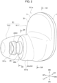
- an outline of an earplug 91 according to Embodiment 1 will be described with reference to FIGS. 1 and 2 .
- the earplug 91 described below is for the right ear, and earplugs for the right ear and the left ear have a left/right symmetrical shape.
- the front, rear, up, down, left, and right directions are defined as the directions of the arrows illustrated in FIGS. 1 and 2 .
- the up-down direction is the vertical direction when the wearer of the earplug 91 is in the standing position.
- the front-rear direction corresponds to the front-rear direction of the head.
- the left-right direction corresponds to the left-right direction of the head.
- the front, rear, up, down, right, and left directions are denoted by FR, RR, UP, DN, RT, and LT, respectively.
- the earplug 91 While being mounted on an auricle E, the earplug 91 has a body part 911 that is fitted in a conchal cavity Eb and an insertion part 912 that protrudes from the body part 911 and is inserted into an ear canal.
- the insertion part 912 is formed of silicone rubber or the like and has elasticity.
- the insertion part 912 is detachably attached to the body part 911.
- the state in which the earplug 91 is mounted on the auricle E is also referred to as a use state.
- the body part 911 has a base 911a, a protrusion 911b, and a locking protrusion 911c.
- the base 911a has an ellipsoidal shape obtained by forming an oval into a flatted solid shape.
- the protrusion 911b protrudes toward the left and obliquely upward and is formed at a position biased to the front of the surface facing the conchal cavity Eb when the earplug is mounted on the auricle E.
- the locking protrusion 911c protrudes from the end side of the protrusion 911b in the protrusion direction along the axial direction of the protrusion 911b and has a smaller diameter than the protrusion 911b.
- the insertion part 912 is elastically locked to the locking protrusion 911c.
- the insertion part 912 is inserted into the ear canal and the base 911a of the body part 911 is fitted in the conchal cavity Eb.
- the front side of the base 911a enters between the conchal cavity Eb and a tragus Ec so as to be sandwiched therebetween, and the rear side of the base 911a enters the inner side of an anthelix Ea, which projects to cover the conchal cavity Eb. Accordingly, the earplug 91 is stably mounted on the auricle E as long as no excessive external force in the direction of separation is applied.
- the body part 911 includes an outer housing 1, an inner housing 2, and a cover 3 as illustrated in FIG. 3 .
- the outer housing 1 and the inner housing 2 are formed of a hard resin.
- the hard resin is a polycarbonate (PC), for example.
- the cover 3 is formed of a flexible material. Examples of such a material include elastomers, silicone rubber, and the like.
- FIG. 4 is a partial cross-sectional view of the body part 911 along line S4-S4 of FIG. 2 .
- the outer housing 1 has a nearly flat bottom wall 1a and an outer peripheral wall 1e that is raised and curved from the entire outer edge of the bottom wall 1a.
- the outer peripheral wall 1e has a circumferential step part 1d which is hollowed out along the whole circumference of the outer peripheral wall 1e toward the right, at the inner edge of the left tip surface of the outer peripheral wall 1e.
- an inner rib 1b protruding to the left at a height lower than the outer peripheral wall 1e is formed along the entire outer edge of the bottom wall 1a.
- the inner housing 2 has a base 21d and an engagement projection 21b.
- the base 21d faces the bottom wall 1a of the outer housing 1.
- the engagement projection 21b protrudes toward the right near the peripheral edge of the base 21d along the whole circumference of the base 21d.
- the peripheral edge of the base 21d forms an outer flange 21a protruding more outward than the engagement projection 21b.
- a cylindrical protrusion 22 is formed which protrudes to the left and obliquely upward. From the tip surface of the protrusion 22, a cylindrical part 23 with a smaller diameter than the protrusion 22 extends along the axis of the protrusion 22.
- the above described locking protrusion 911c visible as part of the external appearance is this cylindrical part 23.
- the outer housing 1 and the inner housing 2 can be combined by entering the engagement projection 21b of the inner housing 2 into a circumferential recess 1c for the engagement projection 21b to engage with the circumferential recess 1c.
- the circumferential recess 1c is a recess between the outer peripheral wall 1e of the outer housing 1 and the inner rib 1b. While the outer housing 1 and the inner housing 2 are combined, the circumferential step part 1d of the outer housing 1 and the circumferential step part 21c of the inner housing 2 face each other in the left-right direction with a gap therebetween.
- the cover 3 has a cover base 31 as an intermediate part in the left-right direction and a cylindrical protrusion 32.
- the cover base 31 has the same outer shape as the outer housing 1.
- the cylindrical protrusion 32 has a bottomed cylindrical shape protruding toward the left and obliquely upward from a position biased to the front of the cover base 31.
- An opening 34 is formed in a shoulder 32b, which serves as a wall to cover the end of the cylinder of the cylindrical protrusion 32.
- the inner diameter of the opening 34 is larger than the outer diameter of the cylindrical part 23 of the inner housing 2.
- the cover base 31 has an inner flange 31a protruding inward along the whole circumference at the peripheral edge of the cover base 31, and a circumferential rib 31b that protrudes along the whole circumference of the inner flange 31a to the right from the inner edge of the inner flange 31a.
- the circumferential rib 31b is a first end on the right side in the left-right direction.
- the cylindrical protrusion 32 is a second end opposite to the first end with the intermediate part (the cover base 31) therebetween.
- the circumferential rib 31b fits in the gap formed between the circumferential step part 1d and the circumferential step part 21c when the outer housing 1 and the inner housing 2 are combined.
- the outer housing 1 and the inner housing 2 can be closely combined with the cover base 31 therebetween.
- the body part 911 of the earplug 91 is formed by combining and integrating, by means of welding or bonding, the outer housing 1 and the inner housing 2 with the circumferential rib 31b of the cover base 31 therebetween.
- the circumferential rib 31b is sealed and fixed by being fitted in the gap formed between the circumferential step part 1d on the inner housing 2 side and the circumferential step part 21c of the inner housing 2.
- the cylindrical part 23 of the inner housing 2 is inserted into the opening 34 of the cover 3 in a natural state in which no external force is applied.
- the cover base 31 of the cover 3 is separated to the left from the base 21d of the inner housing 2. That is, an air chamber V as a space is formed between the cover base 31 and the base 21d in the natural state.
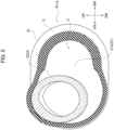
- FIG. 5 illustrates the formation range of the air chamber V, for example.
- FIG. 5 is a cross-sectional view along line S5-S5 of FIG. 4 as viewed from the left side at a position slightly to the left from the base 21d of the inner housing 2.
- the air chamber V is formed in a wide area corresponding to the external shape of the base 911a.
- the cover 3 is formed of a material with a certain degree of flexibility, and the shape of the air chamber V is well maintained in the natural state.
- the air chamber V extends to the left along the protrusion 22 of the inner housing 2 as illustrated in FIG. 4 .
- the cover 3 is in close contact with the protrusion 22 at a position close to the tip of the protrusion 22 in the natural states. That is, the left-hand edge position of the air chamber V in the natural state is a boundary position at which the cover 3 is in close contact with the protrusion 22 at a position close to the tip of the protrusion 22.
- the inner flange 31a side of the cover base 31 of the cover 3, which is the right-hand edge side, is interposed and sealed between the inner housing 2 and the outer housing 1.
- the tip side portion of the cylindrical protrusion 32 including the opening 34 in the cover 3 and the inner housing 2 work together to form a valve structure (a pressure regulator) BK that controls the entry and exit of the air between the interior of the air chamber V and an outer space. That is, the earplug 91 has the air chamber V and the valve structure BK that control the entry and exit of air in/from the air chamber V.
- a valve structure a pressure regulator
- FIG. 6A is a longitudinal cross-sectional view of the protrusion 911b of the body part 911, and specifically is a cross-sectional view along line S6-S6 in FIG. 2 .
- the protrusion 22 of the inner housing 2 has a cylindrical part 22a extending in a cylindrical shape with an axis CL22 as the axis, a top wall 22t which is substantially perpendicular to the axis CL22 and substantially covers the cylinder, and a shoulder 22b curving and smoothly connecting the tip of the cylindrical part 22a and the edge of the top wall 22t.
- the cover 3 is mounted such that an outer surface 22t1 of the top wall 22t and the tip side portion of an outer surface 22b1 of the shoulder 22b (a portion closer to the tip side than a close contact boundary line LN1 in FIG. 6A ) are in close contact with the protrusion 22 of the inner housing 2.
- the close contact boundary line LN1 is a line indicating the position at which the cover 3 begins to contact the protrusion 22.
- the inner surface of the cylindrical protrusion 32 of the cover 3 is formed in the same shape as the outer surface of the protrusion 22 of the inner housing 2 on the side closer to the tip than the close contact boundary line LN1.
- a side part 32a of the cylindrical protrusion 32 is in close contact with the cylindrical part of the protrusion 22 with the close contact boundary line LN1 as a boundary.
- the shoulder 32b of the cylindrical protrusion 32 is in close contact with the shoulder 22b of the protrusion 22. Accordingly, in the earplug 91, the valve structure BK is closed in the natural state, the air chamber V is sealed, and no internal air is leaked to the outside.
- the opening 34 of the cover 3 is coaxial with the cylindrical part 23 of the inner housing 2 and is formed to have an inner diameter larger than the outer diameter of the cylindrical part 23. Therefore, a gap F1 of a distance D1 in the radial direction is formed between the base part of the cylindrical part 23 and the end face of the opening 34.
- the user grips the body part 911 with the fingers and presses the body part 911 to fit into the conchal cavity Eb while inserting the insertion part 912 into the ear canal.
- the cover base 31 of the cover 3 is pressed against the surface of the conchal cavity Eb and is elastically deformed such that the distance between the cover base 31 and the base 21d of the inner housing 2 is reduced. This compresses the air chamber V.
- the valve structure BK opens and the air inside the air chamber V is discharged to the outside. This state is illustrated in FIG. 6B .
- the internal pressure of the air chamber V rises and reaches a prescribed value
- the internal pressure pushes and expands the cylindrical protrusion 32 of the cover 3 against the elastic repulsive force of the area of the cylindrical protrusion 32 and an air passage fa is formed between the cylindrical protrusion 32 and the inner housing 2 as illustrated in FIG. 6B . That is, the cylindrical protrusion 32 is expanded and deformed to form the air passage fa.
- the air passage fa communicates between the air chamber V and an outer space Vg through the opening 34. Accordingly, the air inside the air chamber V is discharged to the outside through the air passage fa, and the pressure inside the air chamber V falls.
- the load on the head is reduced when the earplug 91 is mounted on the auricle E or when the body part 911 of the earplug 91 is pressed against the conchal cavity Eb while the earplug 91 is mounted on the auricle E. More specifically, when the body part 911 is pressed against the conchal cavity Eb, the air chamber V is compressed but sealed and shrinks elastically because there is no air discharge path. In accordance with this, an elastic repulsive force of the air chamber V and the cover 3 is applied to the conchal cavity Eb, and therefore the contact feel of the body part 911 is soft and good. In this way, it is possible to enhance the wearing sensation of the body part 911 fitted in the conchal cavity Eb.
- the entire cover 3 in the circumferential direction in the valve structure BK is not uniformly in close contact with the inner wall of the auricle E. Therefore, the air passage fa is not formed in the entire circumferential direction, but first in the area where there is a gap between the cover 3 and the inner wall of the auricle E. For the discharge of the pressurized air in the air chamber V, it is sufficient if the air passage fa is formed in part in the circumferential direction.
- the air chamber V expands from the collapsed state by means of a restoring force that tries to return the shape of the cover 3 to the initial shape.
- the air passage fa is maintained and air flows into the air chamber V from the opening 34.
- the body part 911 As a mode of use in which the body part 911 is pressed more strongly against the conchal cavity Eb while the earplug 91 is mounted on the auricle E, there is a mode in which the user lies on the his/her side while wearing the earplug 91, and the user's head is resting on a pillow. In this mode, the earplug 91 is pressed against the head by means of the pillow. In this mode, by the earplug 91 having the air chamber V and the valve structure BK, the body part 911 makes soft contact with the conchal cavity Eb. Accordingly, the user can have a good wearing sensation.
- FIG. 7A is a longitudinal cross-sectional view of a state in which the earplug 91B is normally mounted on the auricle E.
- FIG. 7B is an enlarged view of part of FIG. 7A.
- FIG. 7C is a longitudinal cross-sectional view of the process of mounting the earplug 91B on the auricle E.
- the valve structure BK2 has a cover 3B instead of the cover 3 of the valve structure BK.
- a side part 32a and a shoulder 32b of the cover 3B are formed so as to create a gap F2 along the whole circumference of the protrusion 22, spaced apart from the protrusion 22 of the inner housing 2 in the natural state.
- the valve structure BK2 has an air passage fb communicating with the air chamber V, between the cover 3B and the protrusion 22.
- An opening 34B with an inner diameter slightly smaller than the outer diameter of the cylindrical part 23 of the inner housing 2 is formed in the shoulder 32b of the cover 3B.
- the peripheral edge of the opening 34B is a ring-shaped flap 35 that is thin and easily flexed and deformed.
- the space on the air passage fb side is separated from the outer space Vg.
- the inner flap 35a and the outer flap 35b are bent to allow ventilation in a direction that reduces the pressure difference, and a gap is formed between the inner and outer flaps 35a, 35b and the outer wall of the cylindrical part 23.
- This gap is not limited to a gap along the whole circumference of the outer wall of the cylindrical part 23, and may be formed in a portion in the circumferential direction.
- the earplug 91 When the earplug 91 is mounted on the auricle E, if the cover 3B is pressed against the conchal cavity Eb, the air chamber V is collapsed, and the air chamber V is pressurized, the inner flap 35a and the outer flap 35b deform such that the pressurized air in the air chamber V is discharged into the outer space Vg as an airflow ARb, as illustrated in FIG. 7C , for example.
- the air chamber V of the cover 3B is expanded and decompressed from the collapsed state by means of the restoring force that tries to restore the shape to the original shape. Accordingly, the inner flap 35a and the outer flap 35b are deformed to allow air inflow from the outer space Vg to the air chamber V.
- the shape of the cover 3B returns to the original shape, the difference between the pressure in the air chamber V and the pressure of the outer space Vg becomes small, the inner flap 35a and the outer flap 35b are in close contact with the cylindrical part 23 again, and the air chamber V becomes sealed again.
- the load on the head is reduced when the earplug 91B is mounted on the auricle E or when the body part 911 of the earplug 91B is pressed against the conchal cavity Eb while the earplug 91B is mounted on the auricle E.
- the air chamber V is compressed, but until a prescribed pressure difference occurs between the air chamber V and the outer space Vg, the sealing of the air chamber V is maintained and there is no air discharge path, and therefore the air chamber V shrinks elastically.
- an elastic repulsive force is applied to the conchal cavity Eb from the cover 3. Therefore, the contact feel is soft and good.
- the body part 911 is pressed more strongly against the conchal cavity Eb, the inside of the air chamber V is pressurized more, and a prescribed pressure difference occurs between the air chamber and the outer space Vg.
- the inner flap 35a and the outer flap 35b of the valve structure BK2 are opened to discharge the internal air of the air chamber V to the outside. Therefore, the air chamber V is decompressed.
- the repulsive force applied to the conchal cavity Eb decreases without becoming excessive despite the strong pressing of the body part 911, and a good contact feel is maintained.
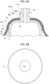
- FIG. 8A is a cross-sectional view of an area near the shoulder 22b of the inner housing 2 for explaining the valve structure BK3 of Embodiment 3, and is a longitudinal cross-sectional view of when the earplug is normally mounted on the auricle.
- FIG. 8B is a plan view of a filter member 5 used in the valve structure BK3.
- the valve structure BK3 has a cover 3C instead of the cover 3 of the valve structure BK, and additionally has the filter member 5.
- the side part 32a and the shoulder 32b of the cover 3C are formed to be separated from the protrusion 22 of the inner housing 2 in the natural state. Accordingly, a gap F3 is formed between the cover 3B and the protrusion 22, and the filter member 5 is interposed in the gap F3.
- the filter member 5 is formed in the gap F3 between the cover 3C and the protrusion 22 to have an approximate bowl shape that is in close contact with both the cover 3C and the protrusion 22.
- an opening 5a is formed through which the cylindrical part 23 can be inserted.
- the filter member 5 is formed of a material through which air can pass while receiving resistance. That is, the filter member 5 is a vent resistor. Examples of such materials are porous materials such as urethane foam.
- the valve structure BK3 has the filter member 5 between the air chamber V and the outer space Vg.
- the filter member 5 functions as an air passage fc that allows ventilation between the air chamber V and the outer space Vg with resistance. Therefore, when the earplug 91C is fitted into the conchal cavity Eb, even if the cover 3C is pressed in contact with the conchal cavity Eb and the air chamber V is compressed and deformed, the air in the air chamber V is discharged to the outer space Vg over time due to the resistance of the filter member 5. Therefore, the air chamber V shrinks gradually and elastically. As a result, an elastic repulsive force in accordance with the compressive deformation of the air chamber V is applied to the conchal cavity Eb from the cover 3. Therefore, the contact feel is soft and good.
- valve structure BK3 of the earplug 91C if the earplug 91C is removed from the auricle E while the cover 3C is pressed and deformed, the air chamber V expands from the collapsed state by means of the restoring force that tries to return the shape of the cover 3C to the initial shape, and the air chamber V is decompressed. As a result, outside air flows into the air chamber V through the filter member 5, and the state of the cover 3C returns to the original state.
- FIG. 9 is a partial perspective view illustrating an inner housing 2D of the valve structure BK4 of Embodiment 4.
- FIG. 10 is a cross-sectional view of the area near the shoulder 22b of the inner housing 2D for explaining the valve structure BK4.
- the valve structure BK4 has an inner housing 2D instead of the inner housing 2 in the valve structure BK. Both structures use the cover 3.
- the inner housing 2D differs from the inner housing 2 in that the inner housing 2D has a groove 25.
- the groove 25 is formed on the outer surface of the protrusion 22.
- the groove 25 extends from the base part of the cylindrical part 23 through the shoulder 22b of the protrusion 22 to the cylindrical part 22a and extends in a direction away from the opening 34 in the radial direction.
- the groove 25 is a narrow groove which is recessed inward from the outer surface of the protrusion 22.
- the cross-sectional shape of the groove 25 is not limited, but is rectangular, for example.
- the valve structure BK4 and the valve structure BK use the same cover 3. That is, the cover 3 and the protrusion 22 are in close contact with each other in the natural state at the portions where the groove 25 is present.
- the end of the groove 25 on the cylindrical part 22a side which is the side far from the opening 34, communicates with the air chamber V in the natural state or can communicate by means of the expanded deformation of the cover 3.
- the end of the groove 25 on the cylindrical part 23 side extends to a position visible from the outside through the opening 34 of the cover 3 and communicates with the outer space Vg. That is, the air chamber V and the outer space Vg communicate through the groove 25.
- the groove 25 as an air passage fd has a small cross-sectional area, and a large resistance is generated for ventilation between the air chamber V and the outer space Vg.
- the valve structure BK4 has the groove 25, and the groove 25 serves as the air passage fd that allows the ventilation between the air chamber V and the outer space Vg by imparting a large resistance. Therefore, suppose that when the earplug 91D is fitted into the conchal cavity Eb, the air chamber V is compressed and deformed while the cover 3 is pressed in contact with the conchal cavity Eb. Even in the above case, the air in the air chamber V is not immediately released to the outer space Vg due to the large resistance when passing through the groove 25, the pressurized state of the air chamber V is maintained for a certain time, and the air chamber V gradually and elastically shrinks. This imparts an elastic repulsive force to the conchal cavity Eb. Therefore, the contact feel is soft and good.
- valve structure BK4 of the earplug 91D if the earplug 91D is removed from the auricle E while the cover 3 is pressed and deformed, the air chamber V expands from the collapsed state by means of the restoring force of the cover 3 that tries to return the shape to the initial shape, and the air chamber V is decompressed. As a result, outside air flows gradually into the air chamber V through the groove 25, and the state of the cover 3 returns to the original state.
- FIG. 11 is a partial perspective view illustrating an inner housing 2E of the valve structure BK5.
- FIG. 12 is a cross-sectional view of the area near the shoulder 22b of the inner housing 2E for explaining the valve structure BK5.
- the valve structure BK5 has the inner housing 2E instead of the inner housing 2 in the valve structure BK.
- the inner housing 2E is the same as the inner housing 2 except the inner housing 2E has a plurality of grooves (groove group) 26.
- the groove group 26 includes long grooves 261 and short grooves 262, which are grooves of multiple types (two types in the present embodiment) with different extension lengths.
- the groove group 26 has four long grooves 261 and four short grooves 262 formed alternately on the outer surface of the protrusion 22 of the inner housing 2E at a 45 degree pitch around the axis CL22.
- the long grooves 261 extend from the base part of the cylindrical part 23 through the shoulder 22b of the protrusion 22 to the cylindrical part 22a and extend in the direction away from the opening 34 in the radial direction.
- the long grooves 261 are narrow grooves recessed inward from the outer surface of the protrusion 22.
- the short grooves 262 extend from the base part of the cylindrical part 23 to the shoulder 22b of the protrusion and extend in the direction away from the opening 34 in the radial direction.
- the short grooves 262 are narrow grooves recessed inward from the outer surface of the protrusion 22.
- the short grooves 262 are shorter than the long grooves 261 and do not extend to reach the cylindrical part 22a.
- the valve structure BK5 and the valve structure BK use the same cover 3. That is, the cover 3 and the protrusion 22 are in close contact with each other in the natural state if the long grooves 261 and the short grooves 262 are absent.
- the distance between the end of the cover 3 on the side far from the opening 34 and the opening 34 of each long groove 261 is different from that for each short groove 262.
- the end of each long groove 261 on the side far from the cylindrical part 23 is covered with the cover 3 and does not communicate with the air chamber V.
- the end of each short groove 262 on the side far from the cylindrical part 23 does not communicate with the air chamber V. That is, communication between the groove group 26 and air chamber V is regulated.
- the cover 3 is pressed in contact with the conchal cavity Eb and the air chamber V is compressed and deformed when the earplug 91E is fitted into the conchal cavity Eb.
- the air chamber V communicates with the long grooves 261 first.
- Each long groove 261 functions as an air passage fe allowing the air chamber V and the outer space Vg to communicate.
- the compressed air in the air chamber V is discharged to the outside through the long grooves 261 serving as the air passage fe. Since the long grooves 261 have a small cross-sectional area, a large resistance occurs for the ventilation between the air chamber V and the outer space Vg.
- the pressurized air in the air chamber V is not discharged from the long grooves 261 to the outer space Vg at once, but is discharged over time. Therefore, the air chamber V shrinks gradually and elastically.
- the air chamber V communicates not only with the long grooves 261 but also with the short grooves 262.
- Each short groove 262 functions as an air passage ff allowing the air chamber V and the outer space Vg to communicate. Therefore, the greatly compressed air in the air chamber V due to the large collapse deformation of the cover 3 passes through the air passage fe and the air passage ff of each long groove 261 and each short groove 262 and is discharged to the outer space Vg.
- an amount of pressurized air in the air chamber V in accordance with the collapse deformation can be properly discharged.
- the elastic repulsive force of the air chamber V imparted to the conchal cavity Eb by the cover 3 is not applied to the head with excessive force. That is, the elastic repulsive force of the cover 3 is stably applied to the conchal cavity Eb regardless of the amount of collapse deformation of the cover 3 which collapses in contact with the conchal cavity Eb when the earplug 91E is mounted on the auricle E. Therefore, it is possible to obtain a better wearing sensation.
- An ear mount is not limited to an earplug.
- the ear mount may be what is referred to as an earplug type earphone or a hearing aid that houses a speaker unit inside the body part 911 and emits sound into the ear canal through the cylindrical part 23.
Landscapes
- Engineering & Computer Science (AREA)
- Manufacturing & Machinery (AREA)
- Physics & Mathematics (AREA)
- Acoustics & Sound (AREA)
- Signal Processing (AREA)
- Health & Medical Sciences (AREA)
- General Health & Medical Sciences (AREA)
- Neurosurgery (AREA)
- Otolaryngology (AREA)
- Headphones And Earphones (AREA)
Applications Claiming Priority (3)
| Application Number | Priority Date | Filing Date | Title |
|---|---|---|---|
| JP2021177786A JP7729181B2 (ja) | 2021-10-29 | 2021-10-29 | 耳装着具 |
| JP2021177894A JP7755782B2 (ja) | 2021-10-29 | 2021-10-29 | 耳装着具 |
| JP2021177874A JP7755781B2 (ja) | 2021-10-29 | 2021-10-29 | 耳装着具 |
Publications (2)
| Publication Number | Publication Date |
|---|---|
| EP4175318A1 true EP4175318A1 (de) | 2023-05-03 |
| EP4175318B1 EP4175318B1 (de) | 2024-03-20 |
Family
ID=83692887
Family Applications (1)
| Application Number | Title | Priority Date | Filing Date |
|---|---|---|---|
| EP22201452.4A Active EP4175318B1 (de) | 2021-10-29 | 2022-10-13 | Ohrhalterung |
Country Status (3)
| Country | Link |
|---|---|
| US (1) | US12120489B2 (de) |
| EP (1) | EP4175318B1 (de) |
| CN (1) | CN116074674B (de) |
Families Citing this family (1)
| Publication number | Priority date | Publication date | Assignee | Title |
|---|---|---|---|---|
| US11877110B2 (en) * | 2022-01-13 | 2024-01-16 | Bose Corporation | Flow relief features embedded in cosmetic surface of wearables |
Citations (5)
| Publication number | Priority date | Publication date | Assignee | Title |
|---|---|---|---|---|
| EP1058479A2 (de) * | 1999-05-31 | 2000-12-06 | Sony Corporation | Hörkapsel |
| JP2014057164A (ja) | 2012-09-11 | 2014-03-27 | Wispack:Kk | 耳挿入具 |
| US20200059715A1 (en) * | 2018-08-17 | 2020-02-20 | Cooler Master Technology Inc. | Earphone |
| US20200221201A1 (en) * | 2019-01-07 | 2020-07-09 | Bose Corporation | Ear tip sealing structure |
| EP3902284A1 (de) * | 2019-01-23 | 2021-10-27 | Samsung Electronics Co., Ltd. | Kopfhörer mit ohrinternem mikrofon |
Family Cites Families (11)
| Publication number | Priority date | Publication date | Assignee | Title |
|---|---|---|---|---|
| US8213668B2 (en) * | 2008-11-04 | 2012-07-03 | Merry Electronics Co., Ltd. | In-ear earphone |
| KR101025786B1 (ko) * | 2009-03-30 | 2011-04-04 | 주성원 | 기압조절기능을 갖는 이어폰 |
| US9179211B2 (en) * | 2012-02-08 | 2015-11-03 | Decibullz Llc | Double seal moldable earpiece system |
| US8737665B2 (en) * | 2012-03-30 | 2014-05-27 | Eastern Technologies Holding Limited | Negative pressure earphone |
| US10251790B2 (en) * | 2013-06-28 | 2019-04-09 | Nocira, Llc | Method for external ear canal pressure regulation to alleviate disorder symptoms |
| JP6107581B2 (ja) * | 2013-09-30 | 2017-04-05 | 株式会社Jvcケンウッド | 耳掛け式ヘッドホン |
| EP3073758B1 (de) * | 2013-11-19 | 2021-05-19 | Sony Corporation | Kopfhörer und verfahren zur anpassung akustischer eigenschaften |
| KR20170098527A (ko) * | 2016-02-22 | 2017-08-30 | 삼성전자주식회사 | 인-이어 이어폰 |
| JP6683043B2 (ja) * | 2016-07-11 | 2020-04-15 | 株式会社Jvcケンウッド | イヤホン |
| TWI686183B (zh) * | 2019-03-05 | 2020-03-01 | 英屬開曼群島商康而富控股股份有限公司 | 能提升配戴舒適感的耳塞 |
| US11991495B2 (en) * | 2020-09-29 | 2024-05-21 | Adapto Global ApS | Modular earpiece adaptor |
-
2022
- 2022-09-27 CN CN202211183411.XA patent/CN116074674B/zh active Active
- 2022-10-13 EP EP22201452.4A patent/EP4175318B1/de active Active
- 2022-10-27 US US17/974,842 patent/US12120489B2/en active Active
Patent Citations (5)
| Publication number | Priority date | Publication date | Assignee | Title |
|---|---|---|---|---|
| EP1058479A2 (de) * | 1999-05-31 | 2000-12-06 | Sony Corporation | Hörkapsel |
| JP2014057164A (ja) | 2012-09-11 | 2014-03-27 | Wispack:Kk | 耳挿入具 |
| US20200059715A1 (en) * | 2018-08-17 | 2020-02-20 | Cooler Master Technology Inc. | Earphone |
| US20200221201A1 (en) * | 2019-01-07 | 2020-07-09 | Bose Corporation | Ear tip sealing structure |
| EP3902284A1 (de) * | 2019-01-23 | 2021-10-27 | Samsung Electronics Co., Ltd. | Kopfhörer mit ohrinternem mikrofon |
Also Published As
| Publication number | Publication date |
|---|---|
| EP4175318B1 (de) | 2024-03-20 |
| CN116074674B (zh) | 2025-10-10 |
| US20230133906A1 (en) | 2023-05-04 |
| US12120489B2 (en) | 2024-10-15 |
| CN116074674A (zh) | 2023-05-05 |
Similar Documents
| Publication | Publication Date | Title |
|---|---|---|
| US11825260B2 (en) | Earphone | |
| US7965855B1 (en) | Conformable ear tip with spout | |
| EP3280158A2 (de) | Hörgerät | |
| US8532324B2 (en) | Headphone | |
| US10820084B2 (en) | Ear tip sealing structure | |
| US12004924B2 (en) | Earmuffs | |
| EP3726855B1 (de) | Persönliches hörgerät mit entlüftungskanal und akustischer trennung | |
| EP4175318A1 (de) | Ohrhalterung | |
| US20220248120A1 (en) | Sound output device and attachment aid member | |
| EP2456228A1 (de) | Kopfhörer und elektronische vorrichtung | |
| US20110249855A1 (en) | Earphone | |
| JP7619415B2 (ja) | イヤホン | |
| JP7502010B2 (ja) | 聴取装置、及びイヤホン | |
| JP7755782B2 (ja) | 耳装着具 | |
| JP7755781B2 (ja) | 耳装着具 | |
| JP7729181B2 (ja) | 耳装着具 | |
| KR100962169B1 (ko) | 밀착형 이어폰 | |
| JP2008520337A (ja) | イヤーマフ | |
| JP6834534B2 (ja) | イヤホン | |
| JP5704617B2 (ja) | イヤホン | |
| JP7484238B2 (ja) | イヤーピース、及び耳装着機器 | |
| CN220985820U (zh) | 开放式耳机 | |
| CN113691903A (zh) | 连接组件和耳帽 | |
| KR102417567B1 (ko) | 타원형 노즐을 구비한 마이크로스피커의 이어팁 구조 | |
| CN110858946A (zh) | 用于助听器的听筒的弹性的阻尼元件和助听器 |
Legal Events
| Date | Code | Title | Description |
|---|---|---|---|
| PUAI | Public reference made under article 153(3) epc to a published international application that has entered the european phase |
Free format text: ORIGINAL CODE: 0009012 |
|
| STAA | Information on the status of an ep patent application or granted ep patent |
Free format text: STATUS: REQUEST FOR EXAMINATION WAS MADE |
|
| 17P | Request for examination filed |
Effective date: 20221013 |
|
| AK | Designated contracting states |
Kind code of ref document: A1 Designated state(s): AL AT BE BG CH CY CZ DE DK EE ES FI FR GB GR HR HU IE IS IT LI LT LU LV MC ME MK MT NL NO PL PT RO RS SE SI SK SM TR |
|
| RBV | Designated contracting states (corrected) |
Designated state(s): AL AT BE BG CH CY CZ DE DK EE ES FI FR GB GR HR HU IE IS IT LI LT LU LV MC ME MK MT NL NO PL PT RO RS SE SI SK SM TR |
|
| GRAP | Despatch of communication of intention to grant a patent |
Free format text: ORIGINAL CODE: EPIDOSNIGR1 |
|
| STAA | Information on the status of an ep patent application or granted ep patent |
Free format text: STATUS: GRANT OF PATENT IS INTENDED |
|
| INTG | Intention to grant announced |
Effective date: 20231020 |
|
| RIC1 | Information provided on ipc code assigned before grant |
Ipc: H04R 25/00 20060101ALN20231009BHEP Ipc: H04R 1/10 20060101AFI20231009BHEP |
|
| GRAS | Grant fee paid |
Free format text: ORIGINAL CODE: EPIDOSNIGR3 |
|
| GRAA | (expected) grant |
Free format text: ORIGINAL CODE: 0009210 |
|
| STAA | Information on the status of an ep patent application or granted ep patent |
Free format text: STATUS: THE PATENT HAS BEEN GRANTED |
|
| AK | Designated contracting states |
Kind code of ref document: B1 Designated state(s): AL AT BE BG CH CY CZ DE DK EE ES FI FR GB GR HR HU IE IS IT LI LT LU LV MC ME MK MT NL NO PL PT RO RS SE SI SK SM TR |
|
| REG | Reference to a national code |
Ref country code: GB Ref legal event code: FG4D |
|
| REG | Reference to a national code |
Ref country code: CH Ref legal event code: EP |
|
| REG | Reference to a national code |
Ref country code: IE Ref legal event code: FG4D |
|
| REG | Reference to a national code |
Ref country code: DE Ref legal event code: R096 Ref document number: 602022002454 Country of ref document: DE |
|
| PG25 | Lapsed in a contracting state [announced via postgrant information from national office to epo] |
Ref country code: LT Free format text: LAPSE BECAUSE OF FAILURE TO SUBMIT A TRANSLATION OF THE DESCRIPTION OR TO PAY THE FEE WITHIN THE PRESCRIBED TIME-LIMIT Effective date: 20240320 |
|
| REG | Reference to a national code |
Ref country code: LT Ref legal event code: MG9D |
|
| PG25 | Lapsed in a contracting state [announced via postgrant information from national office to epo] |
Ref country code: GR Free format text: LAPSE BECAUSE OF FAILURE TO SUBMIT A TRANSLATION OF THE DESCRIPTION OR TO PAY THE FEE WITHIN THE PRESCRIBED TIME-LIMIT Effective date: 20240621 |
|
| PG25 | Lapsed in a contracting state [announced via postgrant information from national office to epo] |
Ref country code: HR Free format text: LAPSE BECAUSE OF FAILURE TO SUBMIT A TRANSLATION OF THE DESCRIPTION OR TO PAY THE FEE WITHIN THE PRESCRIBED TIME-LIMIT Effective date: 20240320 Ref country code: RS Free format text: LAPSE BECAUSE OF FAILURE TO SUBMIT A TRANSLATION OF THE DESCRIPTION OR TO PAY THE FEE WITHIN THE PRESCRIBED TIME-LIMIT Effective date: 20240620 |
|
| REG | Reference to a national code |
Ref country code: NL Ref legal event code: MP Effective date: 20240320 |
|
| PG25 | Lapsed in a contracting state [announced via postgrant information from national office to epo] |
Ref country code: RS Free format text: LAPSE BECAUSE OF FAILURE TO SUBMIT A TRANSLATION OF THE DESCRIPTION OR TO PAY THE FEE WITHIN THE PRESCRIBED TIME-LIMIT Effective date: 20240620 Ref country code: NO Free format text: LAPSE BECAUSE OF FAILURE TO SUBMIT A TRANSLATION OF THE DESCRIPTION OR TO PAY THE FEE WITHIN THE PRESCRIBED TIME-LIMIT Effective date: 20240620 Ref country code: LT Free format text: LAPSE BECAUSE OF FAILURE TO SUBMIT A TRANSLATION OF THE DESCRIPTION OR TO PAY THE FEE WITHIN THE PRESCRIBED TIME-LIMIT Effective date: 20240320 Ref country code: HR Free format text: LAPSE BECAUSE OF FAILURE TO SUBMIT A TRANSLATION OF THE DESCRIPTION OR TO PAY THE FEE WITHIN THE PRESCRIBED TIME-LIMIT Effective date: 20240320 Ref country code: GR Free format text: LAPSE BECAUSE OF FAILURE TO SUBMIT A TRANSLATION OF THE DESCRIPTION OR TO PAY THE FEE WITHIN THE PRESCRIBED TIME-LIMIT Effective date: 20240621 Ref country code: FI Free format text: LAPSE BECAUSE OF FAILURE TO SUBMIT A TRANSLATION OF THE DESCRIPTION OR TO PAY THE FEE WITHIN THE PRESCRIBED TIME-LIMIT Effective date: 20240320 Ref country code: BG Free format text: LAPSE BECAUSE OF FAILURE TO SUBMIT A TRANSLATION OF THE DESCRIPTION OR TO PAY THE FEE WITHIN THE PRESCRIBED TIME-LIMIT Effective date: 20240320 |
|
| REG | Reference to a national code |
Ref country code: AT Ref legal event code: MK05 Ref document number: 1668870 Country of ref document: AT Kind code of ref document: T Effective date: 20240320 |
|
| PG25 | Lapsed in a contracting state [announced via postgrant information from national office to epo] |
Ref country code: SE Free format text: LAPSE BECAUSE OF FAILURE TO SUBMIT A TRANSLATION OF THE DESCRIPTION OR TO PAY THE FEE WITHIN THE PRESCRIBED TIME-LIMIT Effective date: 20240320 Ref country code: LV Free format text: LAPSE BECAUSE OF FAILURE TO SUBMIT A TRANSLATION OF THE DESCRIPTION OR TO PAY THE FEE WITHIN THE PRESCRIBED TIME-LIMIT Effective date: 20240320 |
|
| PG25 | Lapsed in a contracting state [announced via postgrant information from national office to epo] |
Ref country code: NL Free format text: LAPSE BECAUSE OF FAILURE TO SUBMIT A TRANSLATION OF THE DESCRIPTION OR TO PAY THE FEE WITHIN THE PRESCRIBED TIME-LIMIT Effective date: 20240320 |
|
| PG25 | Lapsed in a contracting state [announced via postgrant information from national office to epo] |
Ref country code: NL Free format text: LAPSE BECAUSE OF FAILURE TO SUBMIT A TRANSLATION OF THE DESCRIPTION OR TO PAY THE FEE WITHIN THE PRESCRIBED TIME-LIMIT Effective date: 20240320 |
|
| PG25 | Lapsed in a contracting state [announced via postgrant information from national office to epo] |
Ref country code: IS Free format text: LAPSE BECAUSE OF FAILURE TO SUBMIT A TRANSLATION OF THE DESCRIPTION OR TO PAY THE FEE WITHIN THE PRESCRIBED TIME-LIMIT Effective date: 20240720 |
|
| PG25 | Lapsed in a contracting state [announced via postgrant information from national office to epo] |
Ref country code: PT Free format text: LAPSE BECAUSE OF FAILURE TO SUBMIT A TRANSLATION OF THE DESCRIPTION OR TO PAY THE FEE WITHIN THE PRESCRIBED TIME-LIMIT Effective date: 20240722 Ref country code: SM Free format text: LAPSE BECAUSE OF FAILURE TO SUBMIT A TRANSLATION OF THE DESCRIPTION OR TO PAY THE FEE WITHIN THE PRESCRIBED TIME-LIMIT Effective date: 20240320 |
|
| PG25 | Lapsed in a contracting state [announced via postgrant information from national office to epo] |
Ref country code: ES Free format text: LAPSE BECAUSE OF FAILURE TO SUBMIT A TRANSLATION OF THE DESCRIPTION OR TO PAY THE FEE WITHIN THE PRESCRIBED TIME-LIMIT Effective date: 20240320 |
|
| PG25 | Lapsed in a contracting state [announced via postgrant information from national office to epo] |
Ref country code: CZ Free format text: LAPSE BECAUSE OF FAILURE TO SUBMIT A TRANSLATION OF THE DESCRIPTION OR TO PAY THE FEE WITHIN THE PRESCRIBED TIME-LIMIT Effective date: 20240320 Ref country code: EE Free format text: LAPSE BECAUSE OF FAILURE TO SUBMIT A TRANSLATION OF THE DESCRIPTION OR TO PAY THE FEE WITHIN THE PRESCRIBED TIME-LIMIT Effective date: 20240320 |
|
| PG25 | Lapsed in a contracting state [announced via postgrant information from national office to epo] |
Ref country code: AT Free format text: LAPSE BECAUSE OF FAILURE TO SUBMIT A TRANSLATION OF THE DESCRIPTION OR TO PAY THE FEE WITHIN THE PRESCRIBED TIME-LIMIT Effective date: 20240320 |
|
| PG25 | Lapsed in a contracting state [announced via postgrant information from national office to epo] |
Ref country code: PL Free format text: LAPSE BECAUSE OF FAILURE TO SUBMIT A TRANSLATION OF THE DESCRIPTION OR TO PAY THE FEE WITHIN THE PRESCRIBED TIME-LIMIT Effective date: 20240320 |
|
| PG25 | Lapsed in a contracting state [announced via postgrant information from national office to epo] |
Ref country code: SK Free format text: LAPSE BECAUSE OF FAILURE TO SUBMIT A TRANSLATION OF THE DESCRIPTION OR TO PAY THE FEE WITHIN THE PRESCRIBED TIME-LIMIT Effective date: 20240320 |
|
| PG25 | Lapsed in a contracting state [announced via postgrant information from national office to epo] |
Ref country code: SM Free format text: LAPSE BECAUSE OF FAILURE TO SUBMIT A TRANSLATION OF THE DESCRIPTION OR TO PAY THE FEE WITHIN THE PRESCRIBED TIME-LIMIT Effective date: 20240320 Ref country code: SK Free format text: LAPSE BECAUSE OF FAILURE TO SUBMIT A TRANSLATION OF THE DESCRIPTION OR TO PAY THE FEE WITHIN THE PRESCRIBED TIME-LIMIT Effective date: 20240320 Ref country code: RO Free format text: LAPSE BECAUSE OF FAILURE TO SUBMIT A TRANSLATION OF THE DESCRIPTION OR TO PAY THE FEE WITHIN THE PRESCRIBED TIME-LIMIT Effective date: 20240320 Ref country code: PT Free format text: LAPSE BECAUSE OF FAILURE TO SUBMIT A TRANSLATION OF THE DESCRIPTION OR TO PAY THE FEE WITHIN THE PRESCRIBED TIME-LIMIT Effective date: 20240722 Ref country code: PL Free format text: LAPSE BECAUSE OF FAILURE TO SUBMIT A TRANSLATION OF THE DESCRIPTION OR TO PAY THE FEE WITHIN THE PRESCRIBED TIME-LIMIT Effective date: 20240320 Ref country code: IS Free format text: LAPSE BECAUSE OF FAILURE TO SUBMIT A TRANSLATION OF THE DESCRIPTION OR TO PAY THE FEE WITHIN THE PRESCRIBED TIME-LIMIT Effective date: 20240720 Ref country code: ES Free format text: LAPSE BECAUSE OF FAILURE TO SUBMIT A TRANSLATION OF THE DESCRIPTION OR TO PAY THE FEE WITHIN THE PRESCRIBED TIME-LIMIT Effective date: 20240320 Ref country code: EE Free format text: LAPSE BECAUSE OF FAILURE TO SUBMIT A TRANSLATION OF THE DESCRIPTION OR TO PAY THE FEE WITHIN THE PRESCRIBED TIME-LIMIT Effective date: 20240320 Ref country code: CZ Free format text: LAPSE BECAUSE OF FAILURE TO SUBMIT A TRANSLATION OF THE DESCRIPTION OR TO PAY THE FEE WITHIN THE PRESCRIBED TIME-LIMIT Effective date: 20240320 Ref country code: AT Free format text: LAPSE BECAUSE OF FAILURE TO SUBMIT A TRANSLATION OF THE DESCRIPTION OR TO PAY THE FEE WITHIN THE PRESCRIBED TIME-LIMIT Effective date: 20240320 |
|
| PG25 | Lapsed in a contracting state [announced via postgrant information from national office to epo] |
Ref country code: IT Free format text: LAPSE BECAUSE OF FAILURE TO SUBMIT A TRANSLATION OF THE DESCRIPTION OR TO PAY THE FEE WITHIN THE PRESCRIBED TIME-LIMIT Effective date: 20240320 |
|
| REG | Reference to a national code |
Ref country code: DE Ref legal event code: R097 Ref document number: 602022002454 Country of ref document: DE |
|
| PG25 | Lapsed in a contracting state [announced via postgrant information from national office to epo] |
Ref country code: IT Free format text: LAPSE BECAUSE OF FAILURE TO SUBMIT A TRANSLATION OF THE DESCRIPTION OR TO PAY THE FEE WITHIN THE PRESCRIBED TIME-LIMIT Effective date: 20240320 |
|
| PG25 | Lapsed in a contracting state [announced via postgrant information from national office to epo] |
Ref country code: DK Free format text: LAPSE BECAUSE OF FAILURE TO SUBMIT A TRANSLATION OF THE DESCRIPTION OR TO PAY THE FEE WITHIN THE PRESCRIBED TIME-LIMIT Effective date: 20240320 |
|
| PLBE | No opposition filed within time limit |
Free format text: ORIGINAL CODE: 0009261 |
|
| STAA | Information on the status of an ep patent application or granted ep patent |
Free format text: STATUS: NO OPPOSITION FILED WITHIN TIME LIMIT |
|
| PG25 | Lapsed in a contracting state [announced via postgrant information from national office to epo] |
Ref country code: DK Free format text: LAPSE BECAUSE OF FAILURE TO SUBMIT A TRANSLATION OF THE DESCRIPTION OR TO PAY THE FEE WITHIN THE PRESCRIBED TIME-LIMIT Effective date: 20240320 |
|
| 26N | No opposition filed |
Effective date: 20241223 |
|
| PG25 | Lapsed in a contracting state [announced via postgrant information from national office to epo] |
Ref country code: SI Free format text: LAPSE BECAUSE OF FAILURE TO SUBMIT A TRANSLATION OF THE DESCRIPTION OR TO PAY THE FEE WITHIN THE PRESCRIBED TIME-LIMIT Effective date: 20240320 |
|
| PG25 | Lapsed in a contracting state [announced via postgrant information from national office to epo] |
Ref country code: MC Free format text: LAPSE BECAUSE OF FAILURE TO SUBMIT A TRANSLATION OF THE DESCRIPTION OR TO PAY THE FEE WITHIN THE PRESCRIBED TIME-LIMIT Effective date: 20240320 |
|
| PG25 | Lapsed in a contracting state [announced via postgrant information from national office to epo] |
Ref country code: LU Free format text: LAPSE BECAUSE OF NON-PAYMENT OF DUE FEES Effective date: 20241013 Ref country code: BE Free format text: LAPSE BECAUSE OF NON-PAYMENT OF DUE FEES Effective date: 20241031 |
|
| PG25 | Lapsed in a contracting state [announced via postgrant information from national office to epo] |
Ref country code: FR Free format text: LAPSE BECAUSE OF NON-PAYMENT OF DUE FEES Effective date: 20241031 |
|
| REG | Reference to a national code |
Ref country code: BE Ref legal event code: MM Effective date: 20241031 |
|
| PG25 | Lapsed in a contracting state [announced via postgrant information from national office to epo] |
Ref country code: IE Free format text: LAPSE BECAUSE OF NON-PAYMENT OF DUE FEES Effective date: 20241013 |
|
| PGFP | Annual fee paid to national office [announced via postgrant information from national office to epo] |
Ref country code: DE Payment date: 20250902 Year of fee payment: 4 |
|
| PG25 | Lapsed in a contracting state [announced via postgrant information from national office to epo] |
Ref country code: CY Free format text: LAPSE BECAUSE OF FAILURE TO SUBMIT A TRANSLATION OF THE DESCRIPTION OR TO PAY THE FEE WITHIN THE PRESCRIBED TIME-LIMIT; INVALID AB INITIO Effective date: 20221013 |
|
| PG25 | Lapsed in a contracting state [announced via postgrant information from national office to epo] |
Ref country code: HU Free format text: LAPSE BECAUSE OF FAILURE TO SUBMIT A TRANSLATION OF THE DESCRIPTION OR TO PAY THE FEE WITHIN THE PRESCRIBED TIME-LIMIT; INVALID AB INITIO Effective date: 20221013 |