EP4174329A1 - Locking tab-washer - Google Patents
Locking tab-washer Download PDFInfo
- Publication number
- EP4174329A1 EP4174329A1 EP22204816.7A EP22204816A EP4174329A1 EP 4174329 A1 EP4174329 A1 EP 4174329A1 EP 22204816 A EP22204816 A EP 22204816A EP 4174329 A1 EP4174329 A1 EP 4174329A1
- Authority
- EP
- European Patent Office
- Prior art keywords
- opening
- bolt
- locking
- locking tab
- tab washer
- Prior art date
- Legal status (The legal status is an assumption and is not a legal conclusion. Google has not performed a legal analysis and makes no representation as to the accuracy of the status listed.)
- Pending
Links
- 238000000034 method Methods 0.000 claims description 10
- 238000005452 bending Methods 0.000 claims description 4
- 238000005516 engineering process Methods 0.000 description 3
- 239000000567 combustion gas Substances 0.000 description 2
- 239000007789 gas Substances 0.000 description 2
- 238000012986 modification Methods 0.000 description 2
- 230000004048 modification Effects 0.000 description 2
- 238000004891 communication Methods 0.000 description 1
- 230000008878 coupling Effects 0.000 description 1
- 238000010168 coupling process Methods 0.000 description 1
- 238000005859 coupling reaction Methods 0.000 description 1
- 239000000446 fuel Substances 0.000 description 1
- 238000009434 installation Methods 0.000 description 1
- 230000014759 maintenance of location Effects 0.000 description 1
- 238000009877 rendering Methods 0.000 description 1
Images


Classifications
-
- F—MECHANICAL ENGINEERING; LIGHTING; HEATING; WEAPONS; BLASTING
- F16—ENGINEERING ELEMENTS AND UNITS; GENERAL MEASURES FOR PRODUCING AND MAINTAINING EFFECTIVE FUNCTIONING OF MACHINES OR INSTALLATIONS; THERMAL INSULATION IN GENERAL
- F16B—DEVICES FOR FASTENING OR SECURING CONSTRUCTIONAL ELEMENTS OR MACHINE PARTS TOGETHER, e.g. NAILS, BOLTS, CIRCLIPS, CLAMPS, CLIPS OR WEDGES; JOINTS OR JOINTING
- F16B5/00—Joining sheets or plates, e.g. panels, to one another or to strips or bars parallel to them
- F16B5/02—Joining sheets or plates, e.g. panels, to one another or to strips or bars parallel to them by means of fastening members using screw-thread
-
- F—MECHANICAL ENGINEERING; LIGHTING; HEATING; WEAPONS; BLASTING
- F16—ENGINEERING ELEMENTS AND UNITS; GENERAL MEASURES FOR PRODUCING AND MAINTAINING EFFECTIVE FUNCTIONING OF MACHINES OR INSTALLATIONS; THERMAL INSULATION IN GENERAL
- F16B—DEVICES FOR FASTENING OR SECURING CONSTRUCTIONAL ELEMENTS OR MACHINE PARTS TOGETHER, e.g. NAILS, BOLTS, CIRCLIPS, CLAMPS, CLIPS OR WEDGES; JOINTS OR JOINTING
- F16B39/00—Locking of screws, bolts or nuts
- F16B39/02—Locking of screws, bolts or nuts in which the locking takes place after screwing down
- F16B39/10—Locking of screws, bolts or nuts in which the locking takes place after screwing down by a plate, spring, wire or ring immovable with regard to the bolt or object and mainly perpendicular to the axis of the bolt
- F16B39/108—Locking of screws, bolts or nuts in which the locking takes place after screwing down by a plate, spring, wire or ring immovable with regard to the bolt or object and mainly perpendicular to the axis of the bolt with a locking washer under the nut or bolt head having at least one tongue or lug folded against the nut or bolt head, or against the object itself
-
- F—MECHANICAL ENGINEERING; LIGHTING; HEATING; WEAPONS; BLASTING
- F02—COMBUSTION ENGINES; HOT-GAS OR COMBUSTION-PRODUCT ENGINE PLANTS
- F02C—GAS-TURBINE PLANTS; AIR INTAKES FOR JET-PROPULSION PLANTS; CONTROLLING FUEL SUPPLY IN AIR-BREATHING JET-PROPULSION PLANTS
- F02C7/00—Features, components parts, details or accessories, not provided for in, or of interest apart form groups F02C1/00 - F02C6/00; Air intakes for jet-propulsion plants
- F02C7/20—Mounting or supporting of plant; Accommodating heat expansion or creep
-
- F—MECHANICAL ENGINEERING; LIGHTING; HEATING; WEAPONS; BLASTING
- F16—ENGINEERING ELEMENTS AND UNITS; GENERAL MEASURES FOR PRODUCING AND MAINTAINING EFFECTIVE FUNCTIONING OF MACHINES OR INSTALLATIONS; THERMAL INSULATION IN GENERAL
- F16B—DEVICES FOR FASTENING OR SECURING CONSTRUCTIONAL ELEMENTS OR MACHINE PARTS TOGETHER, e.g. NAILS, BOLTS, CIRCLIPS, CLAMPS, CLIPS OR WEDGES; JOINTS OR JOINTING
- F16B39/00—Locking of screws, bolts or nuts
- F16B39/02—Locking of screws, bolts or nuts in which the locking takes place after screwing down
- F16B39/10—Locking of screws, bolts or nuts in which the locking takes place after screwing down by a plate, spring, wire or ring immovable with regard to the bolt or object and mainly perpendicular to the axis of the bolt
- F16B39/101—Locking of screws, bolts or nuts in which the locking takes place after screwing down by a plate, spring, wire or ring immovable with regard to the bolt or object and mainly perpendicular to the axis of the bolt with a plate, spring, wire or ring holding two or more nuts or bolt heads which are mainly in the same plane
-
- F—MECHANICAL ENGINEERING; LIGHTING; HEATING; WEAPONS; BLASTING
- F05—INDEXING SCHEMES RELATING TO ENGINES OR PUMPS IN VARIOUS SUBCLASSES OF CLASSES F01-F04
- F05D—INDEXING SCHEME FOR ASPECTS RELATING TO NON-POSITIVE-DISPLACEMENT MACHINES OR ENGINES, GAS-TURBINES OR JET-PROPULSION PLANTS
- F05D2220/00—Application
- F05D2220/30—Application in turbines
- F05D2220/32—Application in turbines in gas turbines
-
- F—MECHANICAL ENGINEERING; LIGHTING; HEATING; WEAPONS; BLASTING
- F05—INDEXING SCHEMES RELATING TO ENGINES OR PUMPS IN VARIOUS SUBCLASSES OF CLASSES F01-F04
- F05D—INDEXING SCHEME FOR ASPECTS RELATING TO NON-POSITIVE-DISPLACEMENT MACHINES OR ENGINES, GAS-TURBINES OR JET-PROPULSION PLANTS
- F05D2260/00—Function
- F05D2260/30—Retaining components in desired mutual position
- F05D2260/31—Retaining bolts or nuts
Definitions
- the disclosure relates generally to aircraft engines and, more particularly, to fasteners in aircraft engines.
- Locking tab washer as used in aircraft engines to rotatably lock a fastener such as a bolt in place once torqued.
- Typical locking tab washers require a bolt head to be oriented at specific angles to provide satisfactory alignment of the locking tabs with the bolt head flats for locking. As such, the bolt may often require being over or under-torqued from its predetermined torque degree for satisfactory locking alignment. Improvements are thus desirable.
- a locking tab washer for rotatably locking a bolt fastened to a component in an aircraft engine, the bolt having a bolt head with repeated flat surfaces
- the locking tab washer comprising: an opening extending from a front surface of the locking tab washer to a rear surface of the locking tab washer, with an axis defined through a center of the opening; at least four locking tabs positioned about the opening and circumferentially spaced apart from one another at integer multiples of a common angle relative to the center of the opening, the at least four locking tabs bendable towards the opening in a first direction relative to the axis to rotatably lock the bolt; and a retaining feature positioned about the opening and operable to rotatably retain the locking tab washer to the component.
- the at least four locking tabs include four locking tabs circumferentially spaced apart from one another at integer multiples of fifteen degrees.
- a first and a second of the four locking tabs are circumferentially spaced apart by ninety degrees
- the second and a third of the four locking tabs are circumferentially spaced apart by forty five degrees
- the third and a fourth of the four locking tabs are circumferentially spaced apart by ninety degrees.
- a first and a second of the four locking tabs are circumferentially spaced apart by ninety degrees
- the second and a third of the four locking tabs are circumferentially spaced apart by ninety degrees
- the third and a fourth of the four locking tabs are circumferentially spaced apart by ninety degrees.
- the retaining feature includes a pair of anti-rotation tabs, each anti-rotation tab having a first portion extending radially outwardly from the opening and a second portion extending in a second direction relative to the axis opposite the first direction, the anti-rotation tabs operable to engage a radially-outward surface of the component.
- the retaining feature includes at least one foot extending radially outwardly relative to the opening and operable to abut an engagement surface of the component to rotatably retain the locking tab washer to the component.
- the retaining feature includes a key having a first portion extending radially outwardly relative to the opening and a second portion extending in a second direction relative to the axis opposite the first direction, the key operable to engage a slot in the component.
- the locking tab washer further comprises a second opening extending from a front surface of the locking tab washer to a rear surface of the locking tab washer, with a second axis defined through a center of the second opening, at least four additional locking tabs positioned about the second opening and circumferentially spaced apart from one another at integer multiples of forty five degrees with reference to the center of the second opening, the at least four additional locking tabs bendable towards the opening in a first direction relative to the axis to rotatably lock a second bolt insertable through the opening, wherein the retaining feature extends between the opening and the second opening.
- one or more of the at least four locking tabs are pre-bent in the first direction relative to the axis.
- a locking assembly for joining two components in an aircraft engine, comprising: a locking tab washer having an opening extending from a front surface of the locking tab washer to a rear surface of the locking tab washer with an axis defined through a center of the opening, the rear surface disposed against a first of the two components with the opening aligned with apertures in the first of the two components and a second of the two components, at least four locking tabs positioned about the opening and bendable towards the opening in a first direction relative to the axis, and a retaining feature positioned about the opening and engaging an anti-rotation surface of one of the two components; and a bolt having a bolt head with a plurality of flat surfaces, and a shank rotatably received through the opening and through the apertures in the two components, the bolt torqued to a predetermined degree, each of the plurality of flat surfaces of the bolt having a loaded half surface and an unloaded half surface when the bolt is torqued, at least one of the at least four locking tabs bendable
- the retaining feature includes a pair of anti-rotation tabs, each anti-rotation tab having a first portion extending radially outwardly from the opening and a second portion extending in a second direction relative to the axis opposite the first direction, the anti-rotation tabs operable to engage a radially-outward surface of the first component.
- the retaining feature includes a foot extending radially outwardly relative to the opening and operable to abut an engagement surface of the first component to rotatably retain the locking tab washer to the first component.
- the retaining feature includes a key having a first portion extending radially outwardly relative to the opening and a second portion extending in a second direction relative to the axis opposite the first direction, the key operable to engage a slot in the first component.
- the locking tab washer further includes a second opening extending from a front surface of the locking tab washer to a rear surface of the locking tab washer, with a second axis defined through a center of the second opening, at least four additional locking tabs positioned about the second opening and bendable towards the opening in a first direction relative to the second axis to rotatably lock a second bolt insertable through the opening, wherein the retaining feature includes a linking member extends between and operatively coupling the opening and the second opening.
- the at least four locking tabs include four locking tabs circumferentially spaced apart from one another at integer multiples of fifteen degrees.
- a method for joining two components in an aircraft engine comprising: positioning a locking tab washer against a first of the two components with an opening in the locking tab washer aligned with apertures in the first of the two components and in a second of the two components; inserting a bolt through the opening and through the apertures in the two components; torqueing the bolt to a predetermined degree; and bending at least four locking tabs positioned about the opening in the locking tab washer towards a head of the bolt to rotatably lock the bolt, the at least four locking tabs having a predetermined angular distribution about the opening, the predetermined angular distribution selected so that at least one of the at least four locking tabs has at least half of its width aligned with a loaded half surface of a corresponding flat surface of the bolt regardless of a relative angular position between the head of the bolt and the locking tab washer.
- the method further comprises engaging a retaining feature positioned about the opening in the locking tab washer with an engagement surface on at least one of the two components.
- engaging the retaining feature includes positioning a first anti-rotation tab extending radially from the opening against the engagement surface in a direction opposite a direction of a tightening of the bolt.
- engaging the retaining feature includes abutting a foot extending radially outwardly from the opening against the engagement surface.
- the method further comprises inserting a second bolt through a second opening in the locking tab washer and through additional apertures in the two components aligned with the second opening, the second opening operatively coupled to the opening via a linking member, torqueing the second bolt to a second predetermined degree, and bending at least four additional locking tabs positioned about the second opening towards a head of the second bolt to rotatably lock the bolt, at least one of the at least four additional locking tabs having at least half of its width aligned with a loaded half surface of a corresponding flat surface of the second bolt to prevent untorqueing of the second bolt.
- FIG. 1 illustrates an aircraft engine, for instance, a gas turbine engine 10 of a type preferably provided for use in subsonic flight.
- the exemplified engine 10 is depicted in FIG. 1 is a turboprop having a propeller 12.
- the engine 10 has, in serial flow communication, a compressor section 14 for pressurizing the air, a combustor 16 in which the compressed air is mixed with fuel and ignited for generating an annular stream of hot combustion gases, and a turbine section 18 for extracting energy from the combustion gases.
- the engine 10 has a shaft 20 drivingly engaged to the propeller 12 via a reduction gear box 22.
- FIG. 1 depicts engine 10 as a reverseflow turboprop-type engine, the present disclosure is applicable to other engine types as well, for instance turboshaft and turbofan type engines.
- a bolt 40 is operable to retain a first component 50 to an adjacent second component 60.
- the first component 50 is a flange of an exhaust duct
- the second component 60 is a flange of a power turbine stator housing, although other components of the engine 10 may be contemplated as well.
- a locking tab washer 70 is operable to rotatably lock the bolt 40 in place once the bolt 40 is torqued to a predetermined degree, regardless of the rotational orientation of the bolt 40.
- the depicted bolt 40 is a single hex bolt having a bolt head 41 with six flat surfaces 42 about its outer circumference.
- a partially or fully threaded shank (not shown) extends from the shank and is receivable through corresponding apertures (not shown) in the first and second components 50, 60.
- the bolt 40 is fastenable, for instance via a nut (not shown) rotatably engageable with a threaded end of the shank on an opposite side of the second component 60, illustratively on the hidden opposite side of the flange of the second component 60.
- Other means for fastening the bolt for instance threading in one or both of the apertures in the first and second components 50, 60, may be contemplated as well.
- each flat surface 42 of the bolt head 41 is divided into two portions or half surfaces relative to a direction of rotation of the bolt: an unloaded half surface 42a and a loaded half surface 42b.
- pressure applied to one or more of the loaded half surfaces 42b by a corresponding portion of the locking tab washer 70 may prevent the bolt 40 from untorqueing, thereby preventing the assembly 30 from coming apart.
- the depicted locking tab washer 70 includes a front surface 71, a rear surface 72, and a central opening 73 extending from the front surface 71 to the rear surface 72.
- An axis A is defined through a center C 1 of the opening 73.
- the locking tab washer 70 may include at least four locking tabs 74 circumferentially oriented about the opening 73 with reference to the center C 1 so that, when the locking assembly 30 is assembled and the bolt torqued, the locking tabs 74 are indexed at unique locations or positions along the flat surfaces 42 of the bolt 40 so that the bolt may be rotatably locked by at least one locking tab 74, regardless of its rotational orientation.
- Various numbers of locking tabs 74 and relative circumferential spacing between tabs may be contemplated.
- the circularly repeating pattern of the bolt's flat surfaces 42 i.e.
- three hundred degrees divided by six sides of a single hex bolt, giving sixty degrees) may be divided by the number of locking tabs 74 on the locking tab washer 70, and multiple integers of that result may be used as the circumferential spacing between circumferentially adjacent locking tabs 74.
- the depicted locking tab washer 70 in FIG. 3 includes four locking tabs 74 positioned about the opening 73. Based on the above, the locking tabs 74 may be circumferentially spaced apart from each other at integer multiples of fifteen degrees. Illustratively, a first angle ⁇ 1 between circumferentially adjacent locking tabs 74 1 and 74 2 measures ninety degrees, a second angle ⁇ 2 between circumferentially adjacent locking tabs 74 2 and 74 3 measures forty five degrees, and a third angle ⁇ 3 between circumferentially adjacent locking tabs 74 3 and 74 4 measures ninety degrees. Other angles between adjacent locking tabs 74 may be contemplated as well.
- locking tab washers 70 may include more than four locking tabs 74.
- a locking tab washer 70 may include five locking tabs 74 that are circumferentially spaced apart from each other at integer multiples of twelve degrees. In various cases, variations of plus-or-minus one degree may apply with respect to the selected degree (or multiple thereof) of spacing.
- the circumferential spacing between adjacent locking tabs 74 may allow the locking tab washer 70 to rotatably lock the bolt 40 once the bolt 40 is torqued to a predetermined degree regardless of the relative angle between the bolt head 41 and the locking tab washer 70 and without requiring the bolt 40 to be additionally over or under-torqued.
- the locking tabs 74 are bendable at a crease 74a at an intersection between the locking tab 74 and the front surface 71 of the locking tab washer 70.
- the locking tabs 74 are thus bendable towards the opening 73 in a first direction D1 relative to the axis A to rotatably retain or lock the bolt 40 in place once the bolt 40 is torqued, as will be discussed in further detail below.
- the locking tabs 74 are pre-bent along respective creases 74a, thereby rendering the locking tab washer 70 mistake proof and only installable in its correct orientation.
- each locking tab 74 may be pre-bent along respective crease(s) 74a, for instance to indicate the correct orientation for installation.
- each locking tab 74 has a narrowing width as it extends from the crease 74a towards a radially distal end 74b thereof, forming a triangular-like cross-sectional shape.
- Other shapes for the locking tabs 74 may be contemplated as well.
- the locking tab washer 70 further includes a retaining feature to rotatably retain the locking tab washer 74 to the first component 50 and/or the second component 60 by engaging a respective surface on the first component 50 and/or the second component 60 as the bolt 40 is torqued.
- the retaining feature includes a pair of anti-rotation tabs 75 positioned about the circumference of the locking tab washer 70.
- Each anti-rotation tab 75 includes a first portion 75a extending radially outwardly relative to the opening 73 and a second portion extending in a second direction D2 relative to the axis A and opposite the first direction D1.
- the anti-rotation tabs 75 are operable to engage radially outer surfaces of the first component 50 and the second component 60.
- the first component 50 is an exhaust duct having a radially inner surface 51, a flange 52 with an aperture (not shown) for the bolt's shank (not shown) to pass therethrough and a radially outer surface 53 with scalloped edges 54.
- the depicted second component 60, the turbine rotor stator housing similarly has a flange with an aperture (not shown) for the bolt's shank to pass therethrough and a radially outer surface 61 with scalloped edges 62.
- Other engine components may be contemplated as well.
- the anti-rotation tabs 75 are operable to abut against the scalloped edges 54, 62 of the first component 50 and the second component 60, respectively, when the locking tab washer 70 is installed.
- the first portions 75a may be dimensioned, i.e. its radial length, so that only one of the anti-rotation tabs 75 may abut a respective scalloped edge 54 of the first component 50 and a respective scalloped edge 62 of the second component 60 at a time.
- the abutting anti-rotation tab 75 may be alternated, for instance, by rotating the locking tab washer 70 relative to the center C 1 .
- the locking tab washer 70 is positioned against the first component 50 the opening 73 aligned with apertures (not shown) in the components 50, 60.
- the bolt 40 is inserted through the opening 73 and through the apertures in the components 50, 60.
- the bolt 40 is tightened to a predetermined degree.
- the at four locking tabs 74 positioned about the opening 73 in the locking tab washer 70 are bent towards the head 41 of the bolt 40 to rotatably lock the bolt 40, with at least one of the at least four locking tabs 74 having a major portion of its width, for instance at least half of its width, aligned with a loaded half surface 42b of a corresponding flat surface 42 of the bolt 40 to prevent untorqueing of the bolt 40. Variations and additional steps may be contemplated as well.
- the above-described method may further include abutting one of the anti-rotation tabs 75 against the scalloped edges 54 as the bolt 40 is being torqued.
- the selected anti-rotation tab 75 is that which requires the applied pressure, for instance against the other anti-rotation tab 75 via a drift or other like tool, to be in a rotational direction opposite the torqueing of the bolt 40.
- any untorqueing motion will be interrupted by the anti-rotation tab 75 abutting the scalloped edges 54 and/or 62 (or other radially-outward surface of the first 50 or second 60 component).
- FIGS. 4A-4D illustrate four rotational orientations of the bolt 40 with reference to a rotational center C 2 of the bolt 40 aligned with axis A.
- the bolt 40 is rotated by fifteen degrees in a clockwise direction from FIG. 4A to FIG. 4B , from FIG. 4B, to FIG. 4C , and from FIG. 4C, to FIG. 4D to depict the operability of the four locking tabs 74, denoted in FIGS.
- locking tabs 74 2 and 74 4 are operable to rotatably lock the bolt 40 once bent by having at least half of their widths aligned with respective loaded half surfaces 42b.
- locking tabs 74 1 and 74 4 are operable to rotatably lock the bolt 40 once bent by having at least half of their widths aligned with respective loaded half surfaces 42b.
- FIG. 4B In the bolt's position as depicted in FIG. 4A , locking tabs 74 1 and 74 4 are operable to rotatably lock the bolt 40 once bent by having at least half of their widths aligned with respective loaded half surfaces 42b.
- locking tabs 74 1 and 74 3 are operable to rotatably lock the bolt 40 once bent by having at least half of their widths aligned with respective loaded half surfaces 42b.
- locking tabs 74 2 and 74 3 are operable to rotatably lock the bolt 40 once bent by having at least half of their widths aligned with respective loaded half surfaces 42b.
- Other combinations of bolt orientations and locking tabs 74 may be contemplated as well. Regardless of the orientation of the bolt 40, the arrangement of the locking tabs 74 about the opening 73 may ensure that at least one of the locking tabs 74 may prevent untorqueing of the bolt 40.
- the locking tab washer 70 includes a pair of feet 76 extending radially outwardly from the opening 73 and operable to retain the locking tab washer 70 in place.
- the feet 76 are operable to abut against a radially inner surface 51 of the first component 50, illustratively an outer diameter of the exhaust duct.
- one of the two feet 76 may be operable to abut the radially inner surface 51 at a time, for instance based on the direction of rotation of the torqued bolt 40.
- the two feet are shown to be symmetric about a center line L normal to the center C 2 and axis A.
- the two feet 76 may be asymmetric about the center line L, i.e. having different dimensions and shapes.
- the locking tab washer 70 may include a single foot 76 operable to abut the radially inner surface 51 of the first component 50 upon torqueing of the bolt 40.
- Various sizes and shapes of the foot/feet 76 may be contemplated, for instance on the type and dimensions of the first component 50.
- the locking tabs 74 are shown to be circumferentially spaced apart, i.e. having first angle ⁇ 1 , second angle ⁇ 2 , and third angle ⁇ 3 of forty five degrees from one another for optimized bolt locking. Other relative angles second angle ⁇ 1 , ⁇ 2 , ⁇ 3 may be contemplated as well. Other relative angles may be contemplated as well.
- the locking tab washer 70 may include two openings 73 and be operable to rotatably lock two adjacent bolts 40. Each opening 73 has a center C 1 with an axis A protruding therethrough.
- This locking tab washer 70 may be referred to as a gang tab washer, as the retaining feature includes a linking member 77 joining a first opening 73 to a second opening 73.
- Each opening 73 is surrounded by locking tabs 74, illustratively four locking tabs 74. In the depicted case, the locking tabs 74 are shown to be circumferentially spaced apart, i.e.
- each opening 73 is surrounded by locking tabs 74 circumferentially spaced apart in a same arrangement, i.e. with forty five degree spacing between circumferentiallyadjacent locking tabs 74.
- the circumferential arrangement may differ around one opening 73 and around the other.
- the retaining feature i.e. the linking member 77, may not require engagement with the other components of the locking assembly 30, for instance the first component 50 or the second component 60, as the presence of the two torqued bolts 40 provide retention to each other via the linking member 77.
- the locking tab washer 70 may include as a retaining feature a key 78 protruding in the second direction D2 opposite the first direction D1.
- the key 78 has a first portion 78a protruding radially outwardly relative the opening 73 and a second portion 78b protruding in the second direction D2 and operable to engage with a slot in the first component 50 to prevent rotation of the locking tab washer 70 with respect to the first component 50 once installed, thus retaining the bolt 40 to the first component 50 once the bolt 40 is torqued and the locking tabs 74 bent.
- the locking tabs 74 are shown to be circumferentially spaced apart, i.e. having first angle ⁇ 1 , second angle ⁇ 2 , and third angle ⁇ 3 of forty five degrees from one another for optimized bolt locking. Other relative angles second angle ⁇ 1 , ⁇ 2 , ⁇ 3 may be contemplated as well.
- At least some embodiments have a locking tab washer 70 with locking tabs 74 providing bolt-locking functionality independently of the orientation of the bolt head 41, thereby allowing the bolt 40 to be torqued to its predetermined degree rather than under or over-torqued to ensure proper rotational locking, which may improve the bolt's sturdiness and reliability in the locking assembly 30.
Abstract
Description
- The disclosure relates generally to aircraft engines and, more particularly, to fasteners in aircraft engines.
- Locking tab washer as used in aircraft engines to rotatably lock a fastener such as a bolt in place once torqued. Typical locking tab washers require a bolt head to be oriented at specific angles to provide satisfactory alignment of the locking tabs with the bolt head flats for locking. As such, the bolt may often require being over or under-torqued from its predetermined torque degree for satisfactory locking alignment. Improvements are thus desirable.
- In one aspect, there is provided a locking tab washer for rotatably locking a bolt fastened to a component in an aircraft engine, the bolt having a bolt head with repeated flat surfaces, the locking tab washer comprising: an opening extending from a front surface of the locking tab washer to a rear surface of the locking tab washer, with an axis defined through a center of the opening; at least four locking tabs positioned about the opening and circumferentially spaced apart from one another at integer multiples of a common angle relative to the center of the opening, the at least four locking tabs bendable towards the opening in a first direction relative to the axis to rotatably lock the bolt; and a retaining feature positioned about the opening and operable to rotatably retain the locking tab washer to the component.
- In a further embodiment of the above, the at least four locking tabs include four locking tabs circumferentially spaced apart from one another at integer multiples of fifteen degrees.
- In a further embodiment of any of the above, a first and a second of the four locking tabs are circumferentially spaced apart by ninety degrees, the second and a third of the four locking tabs are circumferentially spaced apart by forty five degrees, and the third and a fourth of the four locking tabs are circumferentially spaced apart by ninety degrees.
- In a further embodiment of any of the above, a first and a second of the four locking tabs are circumferentially spaced apart by ninety degrees, the second and a third of the four locking tabs are circumferentially spaced apart by ninety degrees, and the third and a fourth of the four locking tabs are circumferentially spaced apart by ninety degrees.
- In a further embodiment of any of the above, the retaining feature includes a pair of anti-rotation tabs, each anti-rotation tab having a first portion extending radially outwardly from the opening and a second portion extending in a second direction relative to the axis opposite the first direction, the anti-rotation tabs operable to engage a radially-outward surface of the component.
- In a further embodiment of any of the above, the retaining feature includes at least one foot extending radially outwardly relative to the opening and operable to abut an engagement surface of the component to rotatably retain the locking tab washer to the component.
- In a further embodiment of any of the above, the retaining feature includes a key having a first portion extending radially outwardly relative to the opening and a second portion extending in a second direction relative to the axis opposite the first direction, the key operable to engage a slot in the component.
- In a further embodiment of any of the above, the locking tab washer further comprises a second opening extending from a front surface of the locking tab washer to a rear surface of the locking tab washer, with a second axis defined through a center of the second opening, at least four additional locking tabs positioned about the second opening and circumferentially spaced apart from one another at integer multiples of forty five degrees with reference to the center of the second opening, the at least four additional locking tabs bendable towards the opening in a first direction relative to the axis to rotatably lock a second bolt insertable through the opening, wherein the retaining feature extends between the opening and the second opening.
- In a further embodiment of any of the above, one or more of the at least four locking tabs are pre-bent in the first direction relative to the axis.
- In another aspect, there is provided a locking assembly for joining two components in an aircraft engine, comprising: a locking tab washer having an opening extending from a front surface of the locking tab washer to a rear surface of the locking tab washer with an axis defined through a center of the opening, the rear surface disposed against a first of the two components with the opening aligned with apertures in the first of the two components and a second of the two components, at least four locking tabs positioned about the opening and bendable towards the opening in a first direction relative to the axis, and a retaining feature positioned about the opening and engaging an anti-rotation surface of one of the two components; and a bolt having a bolt head with a plurality of flat surfaces, and a shank rotatably received through the opening and through the apertures in the two components, the bolt torqued to a predetermined degree, each of the plurality of flat surfaces of the bolt having a loaded half surface and an unloaded half surface when the bolt is torqued, at least one of the at least four locking tabs bendable towards the bolt head with at least half of its width aligned with a loaded half surface of a corresponding flat surface to prevent untorqueing of the bolt when the bolt is torqued.
- In a further embodiment of the above, the retaining feature includes a pair of anti-rotation tabs, each anti-rotation tab having a first portion extending radially outwardly from the opening and a second portion extending in a second direction relative to the axis opposite the first direction, the anti-rotation tabs operable to engage a radially-outward surface of the first component.
- In a further embodiment of any of the above, the retaining feature includes a foot extending radially outwardly relative to the opening and operable to abut an engagement surface of the first component to rotatably retain the locking tab washer to the first component.
- In a further embodiment of any of the above, the retaining feature includes a key having a first portion extending radially outwardly relative to the opening and a second portion extending in a second direction relative to the axis opposite the first direction, the key operable to engage a slot in the first component.
- In a further embodiment of any of the above, the locking tab washer further includes a second opening extending from a front surface of the locking tab washer to a rear surface of the locking tab washer, with a second axis defined through a center of the second opening, at least four additional locking tabs positioned about the second opening and bendable towards the opening in a first direction relative to the second axis to rotatably lock a second bolt insertable through the opening, wherein the retaining feature includes a linking member extends between and operatively coupling the opening and the second opening.
- In a further embodiment of any of the above, the at least four locking tabs include four locking tabs circumferentially spaced apart from one another at integer multiples of fifteen degrees.
- In a further aspect, there is provided a method for joining two components in an aircraft engine, comprising: positioning a locking tab washer against a first of the two components with an opening in the locking tab washer aligned with apertures in the first of the two components and in a second of the two components; inserting a bolt through the opening and through the apertures in the two components; torqueing the bolt to a predetermined degree; and bending at least four locking tabs positioned about the opening in the locking tab washer towards a head of the bolt to rotatably lock the bolt, the at least four locking tabs having a predetermined angular distribution about the opening, the predetermined angular distribution selected so that at least one of the at least four locking tabs has at least half of its width aligned with a loaded half surface of a corresponding flat surface of the bolt regardless of a relative angular position between the head of the bolt and the locking tab washer.
- In a further embodiment of the above, the method further comprises engaging a retaining feature positioned about the opening in the locking tab washer with an engagement surface on at least one of the two components.
- In a further embodiment of any of the above, engaging the retaining feature includes positioning a first anti-rotation tab extending radially from the opening against the engagement surface in a direction opposite a direction of a tightening of the bolt.
- In a further embodiment of any of the above, engaging the retaining feature includes abutting a foot extending radially outwardly from the opening against the engagement surface.
- In a further embodiment of any of the above, the method further comprises inserting a second bolt through a second opening in the locking tab washer and through additional apertures in the two components aligned with the second opening, the second opening operatively coupled to the opening via a linking member, torqueing the second bolt to a second predetermined degree, and bending at least four additional locking tabs positioned about the second opening towards a head of the second bolt to rotatably lock the bolt, at least one of the at least four additional locking tabs having at least half of its width aligned with a loaded half surface of a corresponding flat surface of the second bolt to prevent untorqueing of the second bolt.
- Reference is now made to the accompanying figures in which:
-
FIG. 1 is a schematic cross sectional view of a gas turbine engine; -
FIG. 2 is a perspective view of a locking assembly in accordance with an embodiment of the present disclosure; -
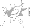
FIG. 3 is a perspective view of a locking tab washer for the locking assembly ofFIG. 2 ; -
FIGS. 4A-4D are front views of the locking assembly ofFIG. 2 with the locking tab washer in various rotational positions; -
FIG. 5 is a front view of a locking assembly in accordance with an embodiment of the present disclosure; -
FIG. 6 is a front view of a locking tab washer in accordance with an embodiment of the present disclosure; -
FIG. 7 is a front view of a locking tab washer in accordance with an embodiment of the present disclosure; -
FIG. 8 is a front view of a locking tab washer in accordance with an embodiment of the present disclosure; and -
FIGS. 9A-9B are front and perspective views, respectively, of a locking tab washer in accordance with an embodiment of the present disclosure. -
FIG. 1 illustrates an aircraft engine, for instance, agas turbine engine 10 of a type preferably provided for use in subsonic flight. The exemplifiedengine 10 is depicted inFIG. 1 is a turboprop having apropeller 12. Theengine 10 has, in serial flow communication, acompressor section 14 for pressurizing the air, acombustor 16 in which the compressed air is mixed with fuel and ignited for generating an annular stream of hot combustion gases, and aturbine section 18 for extracting energy from the combustion gases. Theengine 10 has ashaft 20 drivingly engaged to thepropeller 12 via areduction gear box 22. AlthoughFIG. 1 depictsengine 10 as a reverseflow turboprop-type engine, the present disclosure is applicable to other engine types as well, for instance turboshaft and turbofan type engines. - Referring to
FIG. 2 , anexemplary locking assembly 30 withinengine 10 according to the present disclosure is shown. In the depicted case, although not necessarily the case in all embodiments, abolt 40 is operable to retain afirst component 50 to an adjacentsecond component 60. In the depicted case, thefirst component 50 is a flange of an exhaust duct, and thesecond component 60 is a flange of a power turbine stator housing, although other components of theengine 10 may be contemplated as well. As will be discussed in further detail below, alocking tab washer 70 is operable to rotatably lock thebolt 40 in place once thebolt 40 is torqued to a predetermined degree, regardless of the rotational orientation of thebolt 40. - The depicted
bolt 40 is a single hex bolt having abolt head 41 with sixflat surfaces 42 about its outer circumference. A partially or fully threaded shank (not shown) extends from the shank and is receivable through corresponding apertures (not shown) in the first andsecond components bolt 40 is fastenable, for instance via a nut (not shown) rotatably engageable with a threaded end of the shank on an opposite side of thesecond component 60, illustratively on the hidden opposite side of the flange of thesecond component 60. Other means for fastening the bolt, for instance threading in one or both of the apertures in the first andsecond components flat surface 42 of thebolt head 41 is divided into two portions or half surfaces relative to a direction of rotation of the bolt: anunloaded half surface 42a and a loadedhalf surface 42b. After thebolt 40 is installed and torqued to a predetermined degree, for instance in a clockwise direction when looking at the page, pressure applied to one or more of the loadedhalf surfaces 42b by a corresponding portion of thelocking tab washer 70 may prevent thebolt 40 from untorqueing, thereby preventing theassembly 30 from coming apart. - Referring additionally to
FIG. 3 , the depictedlocking tab washer 70 includes afront surface 71, arear surface 72, and acentral opening 73 extending from thefront surface 71 to therear surface 72. An axis A is defined through a center C1 of theopening 73. Upon assembly of thelocking assembly 30, thebolt 40 is alignable with theopening 73 and apertures (not shown) in thefirst component 50 andsecond component 60 along the axis A. According to various embodiments of the present disclosure, thelocking tab washer 70 may include at least fourlocking tabs 74 circumferentially oriented about the opening 73 with reference to the center C1 so that, when thelocking assembly 30 is assembled and the bolt torqued, thelocking tabs 74 are indexed at unique locations or positions along theflat surfaces 42 of thebolt 40 so that the bolt may be rotatably locked by at least onelocking tab 74, regardless of its rotational orientation. Various numbers oflocking tabs 74 and relative circumferential spacing between tabs may be contemplated. To ensure unique positions or locations along theflat surfaces 42, the circularly repeating pattern of the bolt's flat surfaces 42 (i.e. three hundred degrees divided by six sides of a single hex bolt, giving sixty degrees) may be divided by the number oflocking tabs 74 on thelocking tab washer 70, and multiple integers of that result may be used as the circumferential spacing between circumferentiallyadjacent locking tabs 74. - The depicted
locking tab washer 70 inFIG. 3 includes fourlocking tabs 74 positioned about the opening 73. Based on the above, thelocking tabs 74 may be circumferentially spaced apart from each other at integer multiples of fifteen degrees. Illustratively, a first angle θ1 between circumferentiallyadjacent locking tabs adjacent locking tabs adjacent locking tabs tabs 74 may be contemplated as well. - In other cases, locking
tab washers 70 may include more than four lockingtabs 74. For instance, alocking tab washer 70 may include fivelocking tabs 74 that are circumferentially spaced apart from each other at integer multiples of twelve degrees. In various cases, variations of plus-or-minus one degree may apply with respect to the selected degree (or multiple thereof) of spacing. - As will be discussed in further detail below, the circumferential spacing between adjacent locking
tabs 74 may allow thelocking tab washer 70 to rotatably lock thebolt 40 once thebolt 40 is torqued to a predetermined degree regardless of the relative angle between thebolt head 41 and thelocking tab washer 70 and without requiring thebolt 40 to be additionally over or under-torqued. - In the depicted case, the locking
tabs 74 are bendable at acrease 74a at an intersection between the lockingtab 74 and thefront surface 71 of thelocking tab washer 70. The lockingtabs 74 are thus bendable towards the opening 73 in a first direction D1 relative to the axis A to rotatably retain or lock thebolt 40 in place once thebolt 40 is torqued, as will be discussed in further detail below. In the depicted embodiment, although not necessarily the case in all embodiments, the lockingtabs 74 are pre-bent alongrespective creases 74a, thereby rendering thelocking tab washer 70 mistake proof and only installable in its correct orientation. In other embodiments, one or more of the lockingtabs 74 may be pre-bent along respective crease(s) 74a, for instance to indicate the correct orientation for installation. In the shown case, each lockingtab 74 has a narrowing width as it extends from thecrease 74a towards a radiallydistal end 74b thereof, forming a triangular-like cross-sectional shape. Other shapes for the lockingtabs 74 may be contemplated as well. - The
locking tab washer 70 further includes a retaining feature to rotatably retain thelocking tab washer 74 to thefirst component 50 and/or thesecond component 60 by engaging a respective surface on thefirst component 50 and/or thesecond component 60 as thebolt 40 is torqued. In the embodiment shown inFIGS. 2-3 , the retaining feature includes a pair ofanti-rotation tabs 75 positioned about the circumference of thelocking tab washer 70. Eachanti-rotation tab 75 includes afirst portion 75a extending radially outwardly relative to theopening 73 and a second portion extending in a second direction D2 relative to the axis A and opposite the first direction D1. In an assembled configuration, theanti-rotation tabs 75 are operable to engage radially outer surfaces of thefirst component 50 and thesecond component 60. - As depicted in
FIG. 2 , thefirst component 50 is an exhaust duct having a radiallyinner surface 51, aflange 52 with an aperture (not shown) for the bolt's shank (not shown) to pass therethrough and a radiallyouter surface 53 with scalloped edges 54. The depictedsecond component 60, the turbine rotor stator housing, similarly has a flange with an aperture (not shown) for the bolt's shank to pass therethrough and a radiallyouter surface 61 with scalloped edges 62. Other engine components may be contemplated as well. In the depicted case, theanti-rotation tabs 75 are operable to abut against the scalloped edges 54, 62 of thefirst component 50 and thesecond component 60, respectively, when thelocking tab washer 70 is installed. Thefirst portions 75a may be dimensioned, i.e. its radial length, so that only one of theanti-rotation tabs 75 may abut a respectivescalloped edge 54 of thefirst component 50 and a respectivescalloped edge 62 of thesecond component 60 at a time. The abuttinganti-rotation tab 75 may be alternated, for instance, by rotating thelocking tab washer 70 relative to the center C1. - An exemplary method for joining the two
components locking tab washer 70 is positioned against thefirst component 50 theopening 73 aligned with apertures (not shown) in thecomponents bolt 40 is inserted through theopening 73 and through the apertures in thecomponents bolt 40 is tightened to a predetermined degree. The at four lockingtabs 74 positioned about theopening 73 in thelocking tab washer 70 are bent towards thehead 41 of thebolt 40 to rotatably lock thebolt 40, with at least one of the at least four lockingtabs 74 having a major portion of its width, for instance at least half of its width, aligned with aloaded half surface 42b of a correspondingflat surface 42 of thebolt 40 to prevent untorqueing of thebolt 40. Variations and additional steps may be contemplated as well. - In the embodiment depicted in
FIG. 2 , the above-described method may further include abutting one of theanti-rotation tabs 75 against the scalloped edges 54 as thebolt 40 is being torqued. The selectedanti-rotation tab 75 is that which requires the applied pressure, for instance against theother anti-rotation tab 75 via a drift or other like tool, to be in a rotational direction opposite the torqueing of thebolt 40. Thus, once the bolt is torqued, any untorqueing motion will be interrupted by theanti-rotation tab 75 abutting the scalloped edges 54 and/or 62 (or other radially-outward surface of the first 50 or second 60 component). - Referring additionally to
FIGS. 4A-4D , regardless of the orientation of the torquedbolt 40, at least one of the illustratively four lockingtabs 74 will be in a position to lock thebolt 40 in place once bent towards thebolt head 41 due to its alignment with respective loadedhalf surface 42b.FIGS. 4A-4D illustrate four rotational orientations of thebolt 40 with reference to a rotational center C2 of thebolt 40 aligned with axis A. Illustratively, thebolt 40 is rotated by fifteen degrees in a clockwise direction fromFIG. 4A to FIG. 4B , fromFIG. 4B, to FIG. 4C , and fromFIG. 4C, to FIG. 4D to depict the operability of the fourlocking tabs 74, denoted inFIGS. 4A-4D as 741, 742, 743 and 744. In the bolt's position as depicted inFIG. 4A , lockingtabs bolt 40 once bent by having at least half of their widths aligned with respective loaded half surfaces 42b. In the bolt's position as depicted inFIG. 4B , lockingtabs bolt 40 once bent by having at least half of their widths aligned with respective loaded half surfaces 42b. In the bolt's position as depicted inFIG. 4C , lockingtabs bolt 40 once bent by having at least half of their widths aligned with respective loaded half surfaces 42b. In the bolt's position as depicted inFIG. 4D , lockingtabs bolt 40 once bent by having at least half of their widths aligned with respective loaded half surfaces 42b. Other combinations of bolt orientations and lockingtabs 74 may be contemplated as well. Regardless of the orientation of thebolt 40, the arrangement of the lockingtabs 74 about theopening 73 may ensure that at least one of the lockingtabs 74 may prevent untorqueing of thebolt 40. - In other embodiments, other retaining features for the
locking tab washer 70 may be contemplated. Referring toFIG. 5 , in the depicted embodiment, thelocking tab washer 70 includes a pair offeet 76 extending radially outwardly from theopening 73 and operable to retain thelocking tab washer 70 in place. Once thelocking tab washer 70 is installed on thefirst component 50, illustratively theexhaust duct flange 52, thefeet 76 are operable to abut against a radiallyinner surface 51 of thefirst component 50, illustratively an outer diameter of the exhaust duct. As was the case in the previous embodiment, one of the twofeet 76 may be operable to abut the radiallyinner surface 51 at a time, for instance based on the direction of rotation of the torquedbolt 40. In the embodiment shown inFIG. 5 , the two feet are shown to be symmetric about a center line L normal to the center C2 and axis A. In other cases, for instances as depicted by the locking tab washer shown inFIG. 6 , the twofeet 76 may be asymmetric about the center line L, i.e. having different dimensions and shapes. In other cases, for instance as depicted by thelocking tab washer 70 inFIG. 7 , thelocking tab washer 70 may include asingle foot 76 operable to abut the radiallyinner surface 51 of thefirst component 50 upon torqueing of thebolt 40. Various sizes and shapes of the foot/feet 76 may be contemplated, for instance on the type and dimensions of thefirst component 50. In each of the shown lockingtabs washers 70 ofFIGS. 5-7 , the lockingtabs 74 are shown to be circumferentially spaced apart, i.e. having first angle θ1, second angle θ2, and third angle θ3 of forty five degrees from one another for optimized bolt locking. Other relative angles second angle θ1, θ2, θ3 may be contemplated as well. Other relative angles may be contemplated as well. - Referring to
FIG. 8 , in some embodiments, thelocking tab washer 70 may include twoopenings 73 and be operable to rotatably lock twoadjacent bolts 40. Eachopening 73 has a center C1 with an axis A protruding therethrough. Thislocking tab washer 70 may be referred to as a gang tab washer, as the retaining feature includes a linkingmember 77 joining afirst opening 73 to asecond opening 73. Eachopening 73 is surrounded by lockingtabs 74, illustratively four lockingtabs 74. In the depicted case, the lockingtabs 74 are shown to be circumferentially spaced apart, i.e. having first angle θ1, second angle θ2, and third angle θ3 of forty five degrees from one another for optimized bolt locking. Other relative angles θ1, θ2, θ3 may be contemplated as well. In the depicted case, each opening 73 is surrounded by lockingtabs 74 circumferentially spaced apart in a same arrangement, i.e. with forty five degree spacing betweencircumferentiallyadjacent locking tabs 74. In other cases, the circumferential arrangement may differ around oneopening 73 and around the other. In the depicted case, the retaining feature, i.e. the linkingmember 77, may not require engagement with the other components of the lockingassembly 30, for instance thefirst component 50 or thesecond component 60, as the presence of the two torquedbolts 40 provide retention to each other via the linkingmember 77. - Referring to
FIG. 9 , in some embodiments, thelocking tab washer 70 may include as a retaining feature a key 78 protruding in the second direction D2 opposite the first direction D1. The key 78 has afirst portion 78a protruding radially outwardly relative theopening 73 and asecond portion 78b protruding in the second direction D2 and operable to engage with a slot in thefirst component 50 to prevent rotation of thelocking tab washer 70 with respect to thefirst component 50 once installed, thus retaining thebolt 40 to thefirst component 50 once thebolt 40 is torqued and the lockingtabs 74 bent. In the depictedlocking tabs washer 70 ofFIGS. 9A-9B , the lockingtabs 74 are shown to be circumferentially spaced apart, i.e. having first angle θ1, second angle θ2, and third angle θ3 of forty five degrees from one another for optimized bolt locking. Other relative angles second angle θ1, θ2, θ3 may be contemplated as well. - It can be appreciated from the foregoing that at least some embodiments have a
locking tab washer 70 with lockingtabs 74 providing bolt-locking functionality independently of the orientation of thebolt head 41, thereby allowing thebolt 40 to be torqued to its predetermined degree rather than under or over-torqued to ensure proper rotational locking, which may improve the bolt's sturdiness and reliability in the lockingassembly 30. - The embodiments described in this document provide non-limiting examples of possible implementations of the present technology. Upon review of the present disclosure, a person of ordinary skill in the art will recognize that changes may be made to the embodiments described herein without departing from the scope of the present technology. Yet further modifications could be implemented by a person of ordinary skill in the art in view of the present disclosure, which modifications would be within the scope of the present technology.
Claims (15)
- A locking tab washer (70) for rotatably locking a bolt (40) fastened to a component (50, 60) in an aircraft engine, the bolt (40) having a bolt head (41) with repeated flat surfaces (42), the locking tab washer (70) comprising:an opening (73) extending from a front surface (71) of the locking tab washer (70) to a rear surface (72) of the locking tab washer (70), with an axis (A) defined through a center of the opening (73);at least four locking tabs (74) positioned about the opening (73) and circumferentially spaced apart from one another at integer multiples of a common angle relative to the center of the opening (73), the at least four locking tabs (74) bendable towards the opening (73) in a first direction (D1) relative to the axis (A) to rotatably lock the bolt (40); anda retaining feature positioned about the opening (73) and operable to rotatably retain the locking tab washer (70) to the component (50, 60).
- The locking tab washer (70) as defined in claim 1, wherein the at least four locking tabs (74) include four locking tabs (74) circumferentially spaced apart from one another at integer multiples of fifteen degrees.
- The locking tab washer (70) as defined in claim 2, wherein a first and a second of the four locking tabs (741, 742) are circumferentially spaced apart by ninety degrees, the second and a third of the four locking tabs (742, 743) are circumferentially spaced apart by forty five degrees, and the third and a fourth of the four locking tabs (743, 744) are circumferentially spaced apart by ninety degrees.
- The locking tab washer (70) as defined in claim 2, wherein a first and a second of the four locking tabs (741, 742) are circumferentially spaced apart by ninety degrees, the second and a third of the four locking tabs (742, 743) are circumferentially spaced apart by ninety degrees, and the third and a fourth of the four locking tabs (743, 744) are circumferentially spaced apart by ninety degrees.
- The locking tab washer (70) as defined in any one of claims 1 to 4, wherein the retaining feature includes a pair of anti-rotation tabs (75), each anti-rotation tab (75) having a first portion (75a) extending radially outwardly from the opening (73) and a second portion extending in a second direction (D2) relative to the axis (A) opposite the first direction (D1), the anti-rotation tabs (75) operable to engage a radially-outward surface of the component (50, 60).
- The locking tab washer (70) as defined in any one of claims 1 to 5, wherein the retaining feature includes at least one foot extending radially outwardly relative to the opening (73) and operable to abut an engagement surface of the component (50, 60) to rotatably retain the locking tab washer (70) to the component (50, 60).
- The locking tab washer (70) as defined in any one of claims 1 to 6, wherein the retaining feature includes a key (78) having a first portion (78a) extending radially outwardly relative to the opening (73) and a second portion (78b) extending in a second direction (D2) relative to the axis (A) opposite the first direction (D1), the key (78) operable to engage a slot in the component (50, 60).
- The locking tab washer (70) as defined in any one of claims 1 to 7, further comprising a second opening (73) extending from a front surface (71) of the locking tab washer (70) to a rear surface (72) of the locking tab washer (70), with a second axis (A) defined through a center of the second opening (73), at least four additional locking tabs (74) positioned about the second opening (73) and circumferentially spaced apart from one another at integer multiples of forty five degrees with reference to the center of the second opening (73), the at least four additional locking tabs (74) bendable towards the opening (73) in a first direction (D1) relative to the axis (A) to rotatably lock a second bolt (40) insertable through the opening (73), wherein the retaining feature extends between the opening (73) and the second opening (73).
- The locking tab washer (70) as defined in any one of claims 1 to 8, wherein one or more of the at least four locking tabs (74) are pre-bent in the first direction (D1) relative to the axis (A).
- A locking assembly (30) for joining two components (50, 60) in an aircraft engine, comprising:a locking tab washer (70) as defined in any one of claims 1 to 9, the rear surface (72) of the locking tab washer (70) disposed against a first of the two components (50, 60) with the opening (73) aligned with apertures in the first of the two components (50, 60) and a second of the two components (50, 60), anda bolt (40) having a bolt head (41) with a plurality of flat surfaces (42), and a shank rotatably received through the opening (73) and through the apertures in the two components (50, 60), the bolt (40) torqued to a predetermined degree, each of the plurality of flat surfaces (42) of the bolt (40) having a loaded half surface (42b) and an unloaded half surface (42a) when the bolt (40) is torqued, at least one of the at least four locking tabs (74) bendable towards the bolt head (41) with at least half of its width aligned with a loaded half surface (42b) of a corresponding flat surface (42) to prevent untorqueing of the bolt (40) when the bolt (40) is torqued.
- A method for joining two components (50, 60) in an aircraft engine, comprising:positioning a locking tab washer (70) against a first of the two components (50, 60) with an opening (73) in the locking tab washer (70) aligned with apertures in the first of the two components (50, 60) and in a second of the two components (50, 60);inserting a bolt (40) through the opening (73) and through the apertures in the two components (50, 60);torqueing the bolt (40) to a predetermined degree; andbending at least four locking tabs (74) positioned about the opening (73) in the locking tab washer (70) towards a head of the bolt (40) to rotatably lock the bolt (40), the at least four locking tabs (74) having a predetermined angular distribution about the opening (73), the predetermined angular distribution selected so that at least one of the at least four locking tabs (74) has at least half of its width aligned with a loaded half surface (42b) of a corresponding flat surface (42) of the bolt (40) regardless of a relative angular position between the head of the bolt (40) and the locking tab washer (70).
- The method as defined in claim 11, further comprising engaging a retaining feature positioned about the opening (73) in the locking tab washer (70) with an engagement surface on at least one of the two components (50, 60).
- The method as defined in claim 12, wherein engaging the retaining feature includes positioning a first anti-rotation tab (75) extending radially from the opening (73) against the engagement surface in a direction opposite a direction of a tightening of the bolt (40).
- The method as defined in claim 12, wherein engaging the retaining feature includes abutting a foot extending radially outwardly from the opening (73) against the engagement surface.
- The method as defined in claim 11, further comprising:inserting a second bolt (40) through a second opening (73) in the locking tab washer (70) and through additional apertures in the two components (50, 60) aligned with the second opening (73), the second opening (73) operatively coupled to the opening (73) via a linking member (77);torqueing the second bolt (40) to a second predetermined degree; andbending at least four additional locking tabs (74) positioned about the second opening (73) towards a head of the second bolt (40) to rotatably lock the bolt (40), at least one of the at least four additional locking tabs (74) having at least half of its width aligned with a loaded half surface (42b) of a corresponding flat surface (42) of the second bolt (40) to prevent untorqueing of the second bolt (40).
Applications Claiming Priority (1)
| Application Number | Priority Date | Filing Date | Title |
|---|---|---|---|
| US17/452,883 US20230139607A1 (en) | 2021-10-29 | 2021-10-29 | Locking tab-washer |
Publications (1)
| Publication Number | Publication Date |
|---|---|
| EP4174329A1 true EP4174329A1 (en) | 2023-05-03 |
Family
ID=84047634
Family Applications (1)
| Application Number | Title | Priority Date | Filing Date |
|---|---|---|---|
| EP22204816.7A Pending EP4174329A1 (en) | 2021-10-29 | 2022-10-31 | Locking tab-washer |
Country Status (3)
| Country | Link |
|---|---|
| US (1) | US20230139607A1 (en) |
| EP (1) | EP4174329A1 (en) |
| CA (1) | CA3180310A1 (en) |
Citations (5)
| Publication number | Priority date | Publication date | Assignee | Title |
|---|---|---|---|---|
| US223622A (en) * | 1880-01-13 | Nut-lock | ||
| US955577A (en) * | 1909-10-13 | 1910-04-19 | Richard A Bradshaw | Nut-lock. |
| US4787791A (en) * | 1986-10-31 | 1988-11-29 | Amoco Corporation | Lock washer for bubble cap assembly |
| JP2005076645A (en) * | 2003-08-29 | 2005-03-24 | Hasegawa Seisakusho:Kk | Folded washer |
| US9945411B2 (en) * | 2012-08-31 | 2018-04-17 | United Technologies Corporation | Self-anti-rotating dual lock washer |
Family Cites Families (30)
| Publication number | Priority date | Publication date | Assignee | Title |
|---|---|---|---|---|
| US972086A (en) * | 1909-07-23 | 1910-10-04 | Dugald S Paterson | Nut-lock. |
| US1183729A (en) * | 1914-12-29 | 1916-05-16 | John H Hazel | Nut-lock. |
| US1228679A (en) * | 1916-10-14 | 1917-06-05 | Robert A Lewis | Lock-washer. |
| GB125349A (en) * | 1919-01-21 | 1919-04-17 | William Henry Nosworthy | Improvements in or relating to Nut-locks. |
| US1397252A (en) * | 1921-01-26 | 1921-11-15 | Gwyllym R Holmes | Nut-lock |
| US1441619A (en) * | 1921-09-02 | 1923-01-09 | Bull Dog Lock Washer Co | Nut lock |
| GB203204A (en) * | 1922-09-30 | 1923-09-06 | Frederick Comley | Improvements in or relating to the locking of nuts on screws |
| US1685120A (en) * | 1927-04-09 | 1928-09-25 | Edmund B Carns | Nut lock |
| US1749600A (en) * | 1928-07-11 | 1930-03-04 | Shakeproof Lock Washer Co | Lock nut |
| US1894631A (en) * | 1930-07-18 | 1933-01-17 | Clarence R Owen | Nut lock |
| US1871684A (en) * | 1930-11-29 | 1932-08-16 | Gibbons William James | Locking device for screws and the like |
| GB540325A (en) * | 1941-02-10 | 1941-10-14 | John Banks Dunlop | Nut-lock |
| US2561224A (en) * | 1946-11-15 | 1951-07-17 | Pischek | Locking arrangement for screws |
| FR989915A (en) * | 1948-05-14 | 1951-09-14 | Washer to prevent loosening of the nuts | |
| GB743173A (en) * | 1951-07-02 | 1956-01-11 | Gkn Group Services Ltd | Improvements in screwed fastenings |
| CH346734A (en) * | 1957-05-22 | 1960-05-31 | Majeste La Reine De Droit Du C | Adjustable device for fixing an arm to a tree |
| GB910446A (en) * | 1960-01-01 | 1962-11-14 | Rolls Royce | Improvements in or relating to nuts and bolts |
| GB2138912B (en) * | 1983-04-26 | 1986-08-20 | British Nuclear Fuels Ltd | Locking tab washer |
| US5022875A (en) * | 1989-10-20 | 1991-06-11 | Brunswick Corporation | Marine propeller locking tab washer |
| US5772373A (en) * | 1994-11-02 | 1998-06-30 | Warn Industries, Inc. | Nut and locking device |
| US5618143A (en) * | 1994-11-02 | 1997-04-08 | Warn Industries, Inc. | Spindle nut and locking device |
| FR2922613B1 (en) * | 2007-10-22 | 2010-02-26 | Skf Aerospace France | ROTATING BLOCKING DEVICE OF A SCREW ASSEMBLY, ASSEMBLY COMPRISING SUCH A DEVICE AND USE OF SUCH A ASSEMBLY IN AERONAUTICAL CONSTRUCTION |
| KR20120007307U (en) * | 2011-04-14 | 2012-10-24 | 현대중공업 주식회사 | Washer to prevent bolt rotation |
| FR3026447B1 (en) * | 2014-09-25 | 2016-11-25 | Electricite De France | KEY DEVICE FOR MAINTAINING AN NUT BRAKE |
| US9822666B2 (en) * | 2015-04-06 | 2017-11-21 | United Technologies Corporation | Quad-tab U-washer |
| US9822667B2 (en) * | 2015-04-06 | 2017-11-21 | United Technologies Corporation | Tri-tab lock washer |
| FR3039230B1 (en) * | 2015-07-22 | 2017-07-21 | Snecma | ASSEMBLY COMPRISING A LOCKED FIXING STUD |
| KR20180061719A (en) * | 2016-11-30 | 2018-06-08 | 쌍용자동차 주식회사 | anti-rotation washer of ball joint nut for automobile |
| US11560969B2 (en) * | 2019-09-17 | 2023-01-24 | ASC Engineered Solutions, LLC | Pipe hanger with lock tab washer |
| CN112431843A (en) * | 2020-12-24 | 2021-03-02 | 申秀云 | Screw locking device |
-
2021
- 2021-10-29 US US17/452,883 patent/US20230139607A1/en active Pending
-
2022
- 2022-10-27 CA CA3180310A patent/CA3180310A1/en active Pending
- 2022-10-31 EP EP22204816.7A patent/EP4174329A1/en active Pending
Patent Citations (5)
| Publication number | Priority date | Publication date | Assignee | Title |
|---|---|---|---|---|
| US223622A (en) * | 1880-01-13 | Nut-lock | ||
| US955577A (en) * | 1909-10-13 | 1910-04-19 | Richard A Bradshaw | Nut-lock. |
| US4787791A (en) * | 1986-10-31 | 1988-11-29 | Amoco Corporation | Lock washer for bubble cap assembly |
| JP2005076645A (en) * | 2003-08-29 | 2005-03-24 | Hasegawa Seisakusho:Kk | Folded washer |
| US9945411B2 (en) * | 2012-08-31 | 2018-04-17 | United Technologies Corporation | Self-anti-rotating dual lock washer |
Also Published As
| Publication number | Publication date |
|---|---|
| CA3180310A1 (en) | 2023-04-29 |
| US20230139607A1 (en) | 2023-05-04 |
Similar Documents
| Publication | Publication Date | Title |
|---|---|---|
| US9371863B2 (en) | Turbine engine coupling stack | |
| EP1105622B1 (en) | Mismatch proof variable stator vane | |
| US7011494B2 (en) | Dual retention vane arm | |
| US9249676B2 (en) | Turbine rotor cover plate lock | |
| US20070012129A1 (en) | Adjustable flange arrangement for synchronization of multiple generators | |
| JP2597054B2 (en) | Device for supporting blade segments in gas turbines | |
| US4859149A (en) | Blade locking system | |
| US10393145B2 (en) | Asymmetric alignment system for a variable stator vane | |
| US9133732B2 (en) | Anti-rotation pin retention system | |
| US10247035B2 (en) | Spoke locking architecture | |
| EP4174329A1 (en) | Locking tab-washer | |
| EP3219931B1 (en) | Vane assembly and corresponding gas turbine engine | |
| US10465519B2 (en) | Fastening system for rotor hubs | |
| EP4108939A1 (en) | Nut locking washer | |
| US10415622B2 (en) | Method and system for hybrid gang channel bolted joint | |
| EP1378631A2 (en) | Methods and apparatus for turbine nozzle locks | |
| EP2594751A2 (en) | Stud Retention | |
| US11480212B2 (en) | Nut locking feature | |
| US11414993B1 (en) | Retaining assembly with anti-rotation feature | |
| US20220290615A1 (en) | Mount assembly for accessory gearbox of aircraft engine and associated method of assembly | |
| CN108291673A (en) | Device for being limited the loosening of the nut in turbogenerator | |
| US20240133300A1 (en) | Assembly for a turbomachine blade, comprising a fastener, defining a pocket, and a shim adapted to be received in the pocket at the same time as a root of the blade |
Legal Events
| Date | Code | Title | Description |
|---|---|---|---|
| PUAI | Public reference made under article 153(3) epc to a published international application that has entered the european phase |
Free format text: ORIGINAL CODE: 0009012 |
|
| STAA | Information on the status of an ep patent application or granted ep patent |
Free format text: STATUS: THE APPLICATION HAS BEEN PUBLISHED |
|
| AK | Designated contracting states |
Kind code of ref document: A1 Designated state(s): AL AT BE BG CH CY CZ DE DK EE ES FI FR GB GR HR HU IE IS IT LI LT LU LV MC ME MK MT NL NO PL PT RO RS SE SI SK SM TR |
|
| STAA | Information on the status of an ep patent application or granted ep patent |
Free format text: STATUS: REQUEST FOR EXAMINATION WAS MADE |
|
| 17P | Request for examination filed |
Effective date: 20231101 |
|
| RBV | Designated contracting states (corrected) |
Designated state(s): AL AT BE BG CH CY CZ DE DK EE ES FI FR GB GR HR HU IE IS IT LI LT LU LV MC ME MK MT NL NO PL PT RO RS SE SI SK SM TR |